1
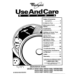
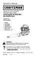
Sears
owners
manual
MODEL NO.
580.326010
CAUTION:
READ
INSTRUCTIONS
AND
RULES FOR SAFE
OPERATIONS CAR E FULLY
TO PREVENT ACCIDENTS,
4500 WATT
HEAVY DUTY
PORTABLE ALTERNATOR
GENERAL INFORMATION
INSTALLATION
OPERATING
INSTRUCTIONS
MAINTENANCE
REPAIR PARTS
ALTERNATOR
Record in space provided below the Model No. and Serial No.
of the alternator, Model No, and Serial No. are both located
on the Nameplate, just below Alternator Control Panel.
Model Noo
Serial No,
Retain these numbers for future reference,,
Sears, Roebuck and Co., Ct-deago, 1]1.60684 U.S.A.
FULL ONE YEAR
WARRANTY
For one year from the date of purchase, Sears will repair any defect
material or workmanship in this alternator at no charge°
If the alternator is used for commercial or rental purposes,
applies for only thirty days from the date of purchase.
Warranty service is available by contacting
Center throughout the United States.
in
this warranty
the nearest Sears Store or Service
This warranty gives you specific legal rights, and you may also have other
rights which vary from state to state.
Sears, Roebuck and Co.
Sears Tower
BSC 41-3
Chicago, I L 60684
INTRODUCTION
Your Owner's
Manual is meant to provide you with instructions
for safe and proper operation
of
the 4500 watt portable
alternator,
Read its contents
carefully
and comply with all instructions
and rules for' safe operation.
With proper care, your alternator
will give years of dependable
electric power.
_IL
Engines
mended
are shipped without oil. Any attempt to start your alternator
oil has been properly added will result in an engine failure.
RULES
_
Your
portable
dangerously
high
qualified
people
operate the unit.
_Never
CAUTION
alternator'
FOR SAFE
produces
voltages,,
Never permit
especially
children
handle
electrical
unto
equipment
while standing
in water, while
barefoot,
while
hands
are wet, This
carl result
dangerous
electrical
shock_
Never
install
the alternator
in any
enclosure
or
compartment
that
might
obstruct
the free flow of cooling
air. Severe
heat damage to the unit will occur.
plosive.
storage
_1_
good
trical
Maintain
electrical
power'
cords
in
condition.
Worn, bare or frayed eleccords are dangerous.
Make sure the wire gauge
sizes of
electrical
power cords
are large enough
to
handle
the largest
anticipated
amperage
of
electrical
equipment.
Using wires that are too
small
to
handle
the
amperage
load
is
dangerous.
Never run the alternator
in any enclosed area. Gasoline
engines
consume
oxygen
and give off DEADLY carbon monoxide
gas.
the recom =
OPERATION
_
or
in
before
Gasoline
is highly
flammable
and ex-
Comply with local laws governing
and handling
of gasoline,
Use care
when
using
the
your' alternator.
Keep clear of moving parts. Never work on the
unit while it is running.
Keep equipment
clean
and check
frequently
for loose,
missing,
rusted
or damaged
nuts, bolts,
and other
fasteners,.
_
Never
try
to adjust
governed
eng]ne
speed. High engine speed is dangerous,
The
alternator
will produce
the required voltage
and frequency
only at 3600 rpm.
TABI.E
OF CONTENTS
WARRANTY .......................
inside Front Cover
RULES FOR SAFE OPERATION
inside Front Cover
SPECIFICATIONS
...............................
1
NOMENCLATURE
...........................................
2
WIRING DIAGRAM ...............................................
3
INSTALLATION
OF STAND-BY
POWER SYSTEMS ...............................
4
REPAIR PARTS ........................................
25-28
Section
1 -- Preparation
For Use
Alternator Unpacking and Removal
From Shipping Skid ..............................
Parts Shipped With Alternator .........................
Wheel Kit Installation
.....................................
Lubrication
...........................................
Battery Installation
................................
Battery Connections
..................................
Fill Fuel Tank .....................................
Install Fuel Tank ................................
Cord Sets for 120 Volt, 15 Amp Outlets .........
Optional Wiring Connections
- 240 Volt
Connector
Plug ..........................
Optional Wiring Connections
- 120 Volt,
30 Amp Connector Plug .......................
Grounding The Alternator ..........................
5
5
7
8
9
9
10
10
10
11
11
12
Section
2 -- Operating
Instructions
Do and Don't Chart ......................................
Before Starting the Engine ................................
Starting the Engine ..................................
Stopping the Engine ................................
Wattage and Power ....................................
Using the 120 Volt, 15 Amp Outlets .................
Using the 120 Volt, 30 Amp Outlet ...............
Using the 240 Volt, 20 Amp Outlet .................
Don't Overload the Alternator .......................
Motor Starting Requirements ........................
Charging a Battery .........................................
Section
3 -- Preventive
13
14
15
16
16
16
16
17
17
17
18
Maintenance
Maintenance Chart .......................................
General Inspection ...................................
Change Oil .............................................
Service Air Cleaner ...............................
Inspect 30 Amp Fuse ...............................
Spark Plugs .........................................
Clean Fuel Tank .......................................
Inspect Cooling Fins ...........................
De-Carbonize Muffler ..................................
Replace Fuel Filter ..................................
De-Carbonize Engine Cylinder Heads ............
Storage ...............................................
19
19
20
21
21
22
22
22
23
23
23
23
SPECIFICATIONS
Model Noo
58&326010
IWattage Capacity
Voltage Output
Amperes
4500 Watts Continuous (5600 watts m'omentary
120f240 Volts
....................................
37.,5 at 120 Voi"ts _18175 at 240"Volts
(Maximum)
Frequency
...... i
....................
..60 Hertz a{ 1800 rpm
== .....
Phase(s)
Solid state "Voltage over Frequency" regulator
2120 volts (_+ 2%) at 60 Hz.
Regulation
......................
Electrical
Outlets
No. of Cylinders
....
Displacemen{ ........
Recommended
Crankcase
Capacity
40 Cubic
Fuel
......... ,,,
Inches (656 cc's)
1800 rpm
5 Gallons
(1&925 Liters)
........
Use clean, fresh NON:LEADED gasot'ine (Leaded, REGULAR
gasoline is an acceptable substitute)
grade
Oil
Spark Plug
Starting
......
"",::',','
L,,,,
Speed
c3 Fuel Tank Capacity
Z
w
maintains
Briggs & Stratton Model No. 401415
Approximatei'y
iO HIP. at 1800 rpm
2
Horsepower
z
...................
(2io' 120 Volt, 15 Amp
(1) - 120 Volt, 30 Amp
(1) - 240 Volt, 20 Amp
..... ,,,
Make and Model
Governed
.......
Single Phase
1800 rpm
Driven Speed
Voltage
surgei .............
Cooling System
Air Cleaner .........................
31/2 Pints (I.65 Liters)
use' Champion
J-8, Auto-Lite A-71i"or AC G046 ......
Set gap to .030 inch
Electric
Ring Gear
.................... Forced airiCentrifugal'
Blower Type) ............................
...............
Dry paper cartridge w"it'lq oil f0ampre-cieaner
'
1
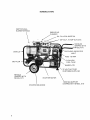
NOMENCLATURE
CENTRIFUGAL
BLOWER SHROUD
ENGINE AIR
CLEANER
OIL FILLER
& DIPSTICK
120 VOLT,
15 AMP OUTLETS
HANDLES
(SHIPPED WITH
WHEEL KIT)
INDICATOR
CRADLE
LIGHT
FUSE - 15 AMP
5 GALLON
FUEL TANK
MUFFLER
NAMEPLATE
12 VOLT
WHEELS
(SHIPPED WITH
WHEEL KIT)
STARTER
STARTER
2
SOLENOID
MOTOR
_IIUSTOME
BATTERY
R SUPPLI ED
RESTING SUPPORT
(SHIPPED WITH WHEEL
KIT)
WIRING
DIAGRAM
Model No. 580.326010
o !ci
_ oooooo
V)
DO
0
0
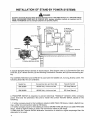
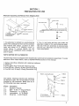
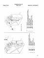
INSTALLATION
OF STAND-BY
POWER SYSTEMS
_I_DANGER
installation of Stand-By Electrical Power Systems should be done by a QUALIFIED electrtctam ALL APPLICABLE ELECTRICAL AND BUILDING CODES MUST BE COMPLIED WITH. improper installation methods or procedures are EXTREMELY DANGEROUS add may damage equipment and personal property°
F! om
To Building
Circuits
Auxiliary Dist
Utility
Line
Meter
To. Bu lid ing
Circuits Powered
_
enter Circuits
By Alternator
Building
Distribution
Box
I
AuxiliaryBuilding
_
1\
Alternator
Panel
TYPICAL
....
_
(For-Alternator
Distribution
Center
Circuit)
Powered
Cord Set
INSTALLATION
A typical Stand-By
Power System is shown above° This System uses a (1) Connection
Box and
Cord Set, (2) a Transfer Switch, (3) two Building
Distribution
Centers, and (4) interconnecting
wiring.
The CONNECTION
following
Stand-By
Model
BOX and CORD SET is used with the 120/240 volt, 4-prong,
Kits are available:
No.
Connection
Box and Cord Set
Transfer
20 amp outlet.
The
Switch
580.322280
120/240 Volt, 4-wire cord set
100 Amp Manual
580.322290
!201240 Volt, 4-wire cord set
200 Amp Manual
A TRANSFER
SWITCH
is required,
to prevent
electrical
"feedback"
between
utility
company
power lines and the alternator.
Be sure to install
the correct Transfer
Switch,
based on the
following:
1. if utility company
input to the building
is rated at LESS THAN 100 Amps, install a Switch having a utility line connection
rated at 100 Amps.
2. If utility company
input to the building
is rated at MORE THAN 100 Amps but LESS THAN 200
Amps, install a Switch having a utility line connection
rated at 200 Amps.
3. Make sure the Transfer
Switch alternator
connection
is rated at a higher amperage
than the
alternator
to be used.
4
SECTION 1
PREPARATION FOR USE
Alternator
Unpacking
and Removal from
Shipping
Skid
¢
"4
|
Wood Sh,pping
Cardboard
Alternator
PatIet
Alternator
Cradle
" !.j
]
?
Insert
Localed
Here
Kit Located
Here
Washer
1 Cut Straps
2. Lift Cardboard
Shtpplng
Carton Straight Up and
Off Shipping
Pallet
Shipping
!
Pallet
_b
1o The alternator
is bolted to a wood shipping
pallet, The cardboard
is then set into position
and retained
with straps., Location
of alternator and wheel
kit in shipping
carton
is
shown
above.
To remove
carton,
cut the
straps and lift cardboard
carton
straight
up
and off pallet°
Bolt
2. Two 1/4 inch bolts and hex nuts retain the
alternator
cradle to the wood shipping
palleL
Use two 7/16 inch wrenches
to remove bolts
and hex nuts° Alternator
can then be removed
from wood pallet°
PARTS SHIPPED WITH ALTERNATOR
The following
items are shipped with the alternator
and must be installed
or assembled.
additional
items listed below, refer to REPAIR PARTS section of this manual.
1_ Battery Hold-Down
2. Wheel Kit
Bracket
with
retaining
To order
hardware
3. One 5 gallon Fuel Tank with retaining
strap
4o One 120 Volt, 3-Prong, 30 Amp Connector
Plug
5. One 240 Volt, 20 Amp, 4-Prong Connector
Plug
Battery Locating Bracket
ITEM 5
__
[_ Item
Description
D1
N2
_3
Bracket (1 Req'd)
Bolt - V4-20 x 7" long (2 Req'd)
Flatwasher%" (2 Req'd)
Lockwasher
- 1/4" (2 Req'd)
Wing Nut - _/4-20 (2 Req'd)
E34
D5
ITEM 4
@_.--.f
The battery
retaining
bracket
and hardware
are shown at right° The 12 volt battery is to be
supplied
by the customer°
Make sure all of
the following
have been received:
ITEM 3
_
t2 Volt Battery
(Customer Supplied )
ITEM I
ITEM 2
5
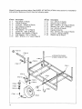
Wheel Kit parts are shown below, See WHEEL KIT INSTALLATIONin this section for installation
instructions. Make sure the Kit has the following parts:
_" Item
[] 1
[] 2
[] 3
[] 4
[] 5
[] 6
[] 7
[] 8
[] 9
[]10
Description
Axle Shaft (1 Req'd)
U-Bolt (2 Req'd)
Lock Nut - 5/16-18(4 Req'd)
Axle Spacer (2 Req'd)
Wheel (2 Req'd)
Flat Washer- a/4"(2 Req'd)
Cotter Pin - 3/32" (2 Req'd)
[_ltem
[] 11
[] 12
[] 13
[] 14
C] 15
[] 16
[] 17
[] 18
[] 19
Support
Leg Cushion
(1 Req'd)"
Flat Washer'7116" (1 Req'd)
Bolt - 5/16-18 x 11/4" long (1 Req'd)
Description
Nut - 5/16-18 (1 Req'd)
Support
Leg (1 Req'd)
Bolt - 5/16-18 x 3/4" tong (2 Req'd)
Washer,
Flat - 5/16" (2 Req'd)
Nut - 5116-t8 (2 Req'd)
Handle (2 Req'd)
Bolt - 318-16 x 2s,4" long (4 Req'd)
Locknut
-3/8-16 (4 Req'd)
Plastic Cap (2 Req'd)
19
ITEM 16
ALTERNATOR
CRADLE
(VIEWED FROM BOTTOM)
ITEM 13
ITEM 18
ITEM 17
ITEM t
/
ITEM 11
ITEM 3
ITEM 12
"
ITEM 14
ITEM 15
ITEM 8 __._!
T-
1
1
ITEM 4
ITEM 5
,6
ITEM 2
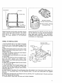
Strap
Bracket
Fuel Tanl<
/
,i,
Rubber
Strap
120 Volt, 30 Amp,
4-Prong Connector Plug
240 Volt, 20 Amp, 4-Prong
Connector Plug
!
Check that both the 5 gallon fuel tank and its
rubber strap have been received.
The rubber
strap has an "S" -Hook at each end that inserts into strap
brackets
on the alternator
cradle°
WHEEL
Check that both the 120 Volt, 3-prong, 30 amp
and the 240 Volt, 4-prong, 20 amp connector
plug
have been received.
See OPTIONAL
CONNECTOR
PLUGS in this section for more
information
on these plugs.
KIT INSTALLATION
Alternator
1. Set Axle Shaft (Item 1) into place and retain
loosely with two U-bolts (Item 2) and 5/16-18
Lock Nuts (item 3). DO NOT TIGHTEN
Lock
Nuts.
2. Slide Axle Spacer (Item 4) over end of Axle
Shaft, followed
by Wheel (item 5) and 3/4" Fiat
Washer (Item 6).
3_ Retain Flat Washer, Wheel and Axle Spacer
with 3/32" Cotter Pin (Item 7).
4. Repeat Steps (2) and (3) above for other side
of Axle Shaft.
5. Center Axle Shaft so that no binding
is evident
and
both
wheels
turn
freely.
Then
tighten
U-bolt Lock Nuts (Item 3) at both ends
of Axle Shaft.
(Viewed
._Item 19
_'-_em
"_'3
te
Item
Item
12 ._j_
10 'I"
Item 7 _m_j
Bottom)
/
16
f
11
Cradle
From
Item
t 3
__
Item3
it_--em__
( !t _Xitem
4 [,.1" item 2
item 5
6o Slide 7116" Fiat Washer (Item 9) over 5116-18
x ! 1/4" bolt (Item t0)o
7_ Insert bolt (Item 10) through
Support
Leg
Cushion
(Item 8) and through
hole in Support
Leg (Item 12) and retain securely
with 5116-i8
Lock Nut (Item 11).
8o Install Support
Leg (Item 12), withCushion
(Item
5/16-18 x 3/4" long Bolts (Item 13), Flat Washers
securely.
8) installed,
onto Alternator
(Item 14), and Lock Nuts
9. install both Handles (Item 16)o Retain with four 3/8-16 x 23/4'' long Bolts
(Item 18). Tighten
all four bolts.
10. Install plastic Caps (Item 19) onto end of both Handles.
(Item
Cradle using two
(Item 15). Tighten
17) and Lock Nuts
7
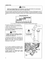
LUBRICATION
CAUTION
Engines are shipped without oil. Any attempt to start the engine before the recommended
oil has been properly added may result in an engine failure.
Service the engine crankcase
with a high quality
detergent
oil having a classification
which includes"For
Service MS, SC, SD or SE", and as recommended
in the following
CHART. Oil recommendations
are the result of extensive
testing°
use no special additives
with the recommended
oilo
Recommended
l
oFT20
o
29
Oil
t
!,
t
49
_ ................
8o
mo
°C- 30
- 20..............
!0 ........... 0
10
20
30
40
"TEMPERATURE RANGE ANTICIPATED BEFORE NEXT OIL CHANGE
*if not available, a synthetic
Fill engine
crankcase
with
1. Remove Oil Dipstick
from
2. Make sure unit is LEVEL.
oil may be used having-
oil as follows:
Oil
3. Pour a measured
31/2 pints
1o65 Liters) of the recommended
Neck_ DO NOT OVERFILL.
Filler
neck.
(56 ounces
or'
oil into Filler'
If engine crankcase is overfilled, a smoking
condition will result as the engine tries to
discharge the surplus oil.
Oii FIHer Neck
Oft Dipstick
A
CAUTION
CAUTION
Do not operate engine
with oll level below
"add 1 pint" mark.
4. Reinstall
Oil Dipstick
ALL THE WAY into
Oil Filler Neck, then remove° Oil should be at
Dipstick
FULL mark° if oil level is BELOW
Dipstick
FULL mark, add oil as required
to
bring level to FULL mark°
FULL
ADD
5o if oil level is ABOVE
the Dipstick
FULL
mark, remove Oil Drain Plug at base of engine
and drain excess oil into asuitable
continer_
Then reinstall
drain plug.
6. When oil level is at Dipstick
FULL mark,
reinstall
Dipstick
into Filler
Neck°
MAKE
SURE DIPSTICK
IS TIGHT.
OIL
DRAIN
PLUG
8
5W-30 or 5W-40 viscosity.
_'
1 PINTt_
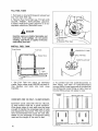
BATTERY INSTALLATION
Battery
Locating
Bracket
ITEM 5
A 12 Volt automotive
type storage
battery is
required,
and must be purchased
separately.
Battery should have a 32 amplhour
(or higher)
capacity°
Install the battery as follows:
_
install the battery
cables
EXACTLY
CAUTION
and connect
as outlined
battery
in this
Manual. Incorrect
battery cable connections will damage
the engine
ignition
system andlor the alternator battery charging circuit,
1. Set battery into place on cradle
battery locating
bracket.
against
the
2. Set the Bracket (Item 1) onto top of battery.
MAKE
SURE
BRACKET
DOES NOT CON*
TACT BATTERY
POSTS.
3o Retain Bracket
with two t/4-20 x 7" long
bolts
(Item 2), Flat Washer
(Item 3), Lock
Washer (item 4), and Wing Nuts (Item 5). Snug
both Wing Nuts down,
but DO NOT OVERTIGHTEN..
BATTERY
h
t2 Volt Battery
(Customer
Supplied
fl
ITEM 2
)
Grounding
Lug For Negative
Battery Cable
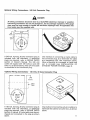
CONNECTIONS
1o The black battery
cable is connected
to a
grounding
lug. Make sure the cable is TIGHT,
then connect
the other end of black cable to
battery post indicated
by a NEGATIVE,
NEG
or (-)o
Black Battery
..To
NEGATIVE,
Battery
Cable
NEG or (-)
Post
2. The red battery
cable is connected
to the
starter solenoid°
Be sure the hex nut that retains the cable is tight. Connect the other end
of the red cable to the battery post indicated
by a POSITIVE,
POS or (4-).
Red BatteQ
Cable
To
POSITIVE, POS
or ( + ) Battery
Post
To
Starter
Motor
9
FILL FUEL TANK
1_ Pull back on knurled fitting
line from tank filler cap.
and remove
fuel
2. Remove Fuel Tank filler cap° Fill tank with
CLEAN,
FRESH,
NON-LEADED
gasoline.
(Leaded,
REGULAR
grade gasoline
is an acceptable
substitute.)
Reinstall
cover.
_
DANGER
Gasoline vapors are highly flammable
and
explosive. Avoid spillage.
Do not permit
smoking, open flame, or sparks in the area
while filling fuel tank.
INSTALL
Strap
2. Remove Filler Cap
FUEL TANK
Bracket
Fuel Tank
/
/
Rubber
Strap
1
T_NK
FILLER
CAP
"S" - Hook
Strap Bracket
Cradle
1. Set Fuel Tank
into place on alternator
cradle. Pass rubber strap UNDER fuel tank lifting
handles
and
hook
into
both
strap
brackets.
2. To connect
fuel line quick-disconnect
to
tank fitting,
pull back on quick-disconnect
knurled fitting.
Insert open end of knurled fuel
line fitting over male fitting on tank, then let
knurled fitting snap into place to locko
AMPERAGE
RATING
CORD SETS FOR 120 VOLT, 15 AMP OUTLETS
Extension
cords used with the two 120 volt,
15 amp outlets
must be in good condition.
Wire gauge sizes of cord sets must be large
enough to handle the amperage
load of tools
and equipment
they power. The chart at right
lists recommended
wire sizes for cord sets,
based on the amperage
of equipment
being
used and the length of the cord in feet.
2
3
4
5
6
8
!0
t2
14
t6
LENGTH OF CORD IN FEET
18 Ga
18 Ga
16 Ga
16 Ga
16 Ga
16 Ga
16 Ga
50 Ga
Ft
14
14 Ga
12 Ga
j
100 Ft
150 F!
18
18
16
16
16
14
14
14
12
12
t8
t8
16
16
14
12
12
12
10
10
Ga,
Ga,
Ga
Ga
Ga.
Ga
Ga
Ga
Ga
Ga
Ga
Ga
Ga
Ga
Ga
Ga
Ga
Ga
Ga
Ga
Outlets
10
Optional Wiring
Connections
- 240 Volt Connector
_1_
Plug
DANGER
All wiring connections should be done by a QUALIFIED electrician. Improper or unauthorized wiring connections are not only dangerous, but may damage equipment. Wire gauge
sizes must be large enough to handle the maximum amperage load. All applicable electrical codes must be complied with.
HOT
HOT
240 Volts
Ground
A 240 volt, 4-prong, 20 amp connector
plug is
included
with
the alternatoro
If additional
plugs are required,
refer to REPAIR PARTS
section
of Owner's
Manual.
The 240 volt
outlet will supply
both 120 volts a-c and 240
volts a-c, as shown above, when a 4-wire cable
is connected
to the connector
plug.
Optional
Wiring
,==,.,...-
Connections
I20 Volts
- 120 Volt,
One method
of connecting
a 4-wire cable to
the connector
plug, is to terminate
the cable
at a connection
box. See illustration
above.
When a Stand-By
kit is ordered, a 4-wire cord
set
is included
(see INSTALLATION
OF
STAND-BY
POWER SYSTEMS,
page 4)_
30 Amp
Connector
Plug
,,,....,.,,_,
/#i"
Ground
!
-2--
L
__1
F"
3-Wlre
Cable
A 120 volt, 3-prong, 30 amp connector
plug is
included
with
the alternatoro
if additional
plugs are required,
refer to REPAIR PARTS
section of manual° A 3-wire cable must be purchased and connected
to the plug as shown
above.
One method of connecting
a 3-wire cable is to
terminate
the cable at an outlet box, as shown
above
11
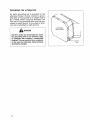
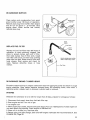
GROUNDING
THE ALTERNATOR
An earth grounding
lug is provided
on the
alternator
blower
shroud.
Connect
a grounding wire to this lug that is no smaller
than a
No, 8 AWG. When using the alternator,
the
free end of the grounding
wire must be connected to earth ground, or to a pipe or structure that is attached
to earth ground°
Centrifugal
BJower Shroud
DANGER
DO NOT, under any circumstances,
attach
the grounding wire to any structure, pipe,
or container that contains a combustible
material. This can result in fire or explosion
in the event the alternator frame becomes
electrically
t2
charged.
Ground
Lug
Section
OPERATING
2
INSTRUCTIONS
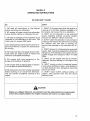
DO AND DON'T
DO
CHART
DON'T
1. DO read all
before operating
instructions
in this
your alternator°
2o DO unplug all power cords from
outlets
before starting
or stopping
Manual
alternator
the unit.
3_ DO add up wattages
of all equipment
to be
powered
by the alternator
at one time. This
total must not exceed 4500 watts,
4o DO remember
that some electric
motors require more WATTS of power for starting
than
for running.
5. DO make sure that wire gauge sizes of electrical cords are large enough
to handle
the
maximum
anticipated
amperage.
6. DO comply
with
storage
and handling
laws pertaining
of gasoline.
7. DO comply
with all instructions
3 of this Manual (MAINTENANCE.)
to
the
in Section
8. DO disconnect
wire from engine spark plug
before working
on or around
the alternator.
This wilt prevent
accidental
starting
of the
engine°
_
1. DON'T fill the gas tank while the engine
is
running or in the dark. Gasoline
spillage on a
hot engine can cause fire or an explosion.
2. DON'T run the alternator
in any enclosed
space°
Gasoline
engines
consume
oxygen
and give off DEADLY carbon monoxide,
3o DON'T install the alternator
in any compartment that will restrict
the free flow of cooling
air. Without
this
free flow
of cooling
air,
serious heat damage to the alternator
wilt occur.
4,. DON'T attempt
to change engine governed
speed° High operating
speeds are extremely
dangerous.
The alternator
wilt produce the required voltage
and frequency
ONLY AT 1800
RPM.
5. DON'T
removed.
result°
run the engine with the air cleaner
Serious
damage to the engine can
6. DON'T unplug or plug in electrical
power
cords while standing
in water, while barefoot,
or while hands are wet. Dangerous
electrical
shock can result.
7. DON'T touch
muffler,
exhaust
engine.
They
become
HOT and
serious burns_
piping,
or
will cause
CAUTION
Engines are shipped without oil, Any attempt to start the engine before the recommended
oil has been properly added to the engine crankcase will result in an engine failure.
13
BEFORE STARTING
THE ENGINE
CAUTION
Do not operate engine
wtth oll levet below
"add 1 pint" mark_
1, Disconnect
Fuel Line
2, Remove Filler Cap
ADD
FULL1 PINT
t. Make sure engine crankcase
has been properly filled with the recommended
oil. See
LUBRICATION
on Page 8.
2. Fill gas tank
with
clean,
fresh,
LEADED gasoline.
(Leaded, REGULAR
gasoline
is an acceptable
substitute_)
NONgrade
k DANGER
Gasoline vapors are highly flammable and explosive. Do not permit smoking, open flame, or
sparks in the vicinity while filling gas tank. Do not allow gasoline to spill on any hot surface.
E
t
TANK FILLER
CAP
J
3o Connect fuel supply hose to gas tank outlet
fitting.
Pull back on the knuded sleeve, insert
hose fitting over tank outlet fitting and let the
sleeve snap into place to lock.
14
Turn FILler Cap
1,_ Turn Counter,
_lo_kwlse
to Vent
Tank
4. Turn gas tank filler cap one-half
counterclockwise
to vent tank,
turn
5. Unplug, disconnect or turn OFF all electrical equipment.
_
CAUTION
Never start the, alternator with electrical
equipment plugged in and turned ON. Correct voltage and frequency
can only be obtained with engine running at governed
speed of 1800 rpm. Some electrical equipment can be damaged by incorrect voltage
and/or frequency.
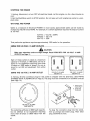
STARTING
THE ENGINE
CHOKI
OPEN
1, To Crank Engine,
Hold StoplStart
Switch To Start
Position
CH OK E
CLOSED
2.
1. Move
CLOSED
Choke
Lever
position.,
all
the
way
down
to
Release Switch
Engine Starts
When
2. Hold Start/Stop
switch
at START position
to crank engine. Release switch when engine
starts. Then open choke gradually
as engine
warms up.
NOTE
Lesser amounts of choking
quired when engine is warm.
may be re-
CAUTION
Do not crank engine continuously for longer than about 30 seconds at a time. Excessively
long cranking periods may result in damage to the starter motor. Each 30 second cranking
period should be followed by at least a 1 minute "cooling
off" period.
t5,
STOPPING
THE
1. Unplug,
cool.
ENGINE
disconnect,
2. Set the StartlStop
plete stop.
WATTAGE
or turn
switch
OFF
all electrical
to STOP
position.
loads.
Let the engine
Do not leave unit until
run for a few minutes
engine
has come
to
to a com-
AND POWER
Watts is a measure
of electrical
POWER. In most cases, approximate
watts can be found by
multiplying
VOLTS times AMPSo For example, if a certain appliance
requires
10 amps of current
at 120 volt:
WATTS
WATTS
WATTS
That particular
appliance
requires
= VOLTS
= 120x10
= 1200
approximately
x AMPS
1200 watts for its operation,
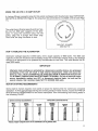
USING THE 120 VOLT, 15 AMP OUTLETS
CAUTION
Make sure extension cords are large
OUTLETS on Page 11.
Each
of these
capacity
tempt to
15 amps
tempt to
outlet.
outlets
is rated
enough.
Read CORD SETS FOR 120 VOLT 15 AMP
|
at a maximum
of 15 amps, or 1800 watts_ Do not atrun equipment
requiring
more than
or" 1800 watts of power. Do not atrun 240 volt equipment
from either
@
_J
USING THE 120 VOLT, 30 AMP OUTLET
A 3-prong, 30 amp connector
SHIPPED WITH ALTERNATOR
(see Page 12.)
,
.
.....
120 VOLT, 15 AMPS
1800 WATTS
plug for this outlet
is shipped
with the
on Page 5.) The plug must be connected
120 VOLT, 15 AMPS
1800 WATTS
alternator.
(See PARTS
to a suitable
cord set
1. Align Prongs,
Insert Plug
2. Twist Plug
Clockwise
120 VOLT, 30 AMP
3600 WATTS
The outlet has a 30 amp or 3600 watt
Do not attempt
to run equipment
more than 30 amps or 3600 watts
outlet.
16
capacity.
requiring
from the
To plug the connector
plug into the outlet,
line up prongs
and insert
plug. Then twist
plug clockwise
to lock.
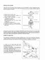
USING
THE
240 VOLT,
20 AMP
OUTLET
A 4-prong, 20 amp connector
plug for this outlet is shipped with
PED WITH ALTERNATOR,
Page 5)° The plug must be connected
11).
the alternator
to a suitable
(see PARTS SHIPcord set (see Page
The outlet has a 20 amp capacity
and can handle the full 4500 watt capacity
of the alternator. To plug the connector
plug into the
outlet,
align the 4 prongs
and insert
plug.
Then twist the plug clockwise
to lock.
240 VOLT, 20 AMPS
4500 WATTS
DON'T
OVERLOAD
THE ALTERNATOR
Alternator
wattage
capacity
is 4500 watts, with a surge capacity
of 5600 watts. The 4500 watt
capacity
of the unit should not be exceeded,
except for momentary
periods. Add up the wattage
ratings of all equipment
to be powered
by the alternator
at one time. This total should not exceed 4500 watts.
IMPORTANT
Alternator stator windings are protected by a temperature sensitive device. Any prolonged
overloading of the unit will result in high internal temperatures,
which will cause this
device to "trip".
NO A-C POWER WILL BE AVAILABLE FROM ALTERNATOR OUTLETS UNTIL INTERNAL TEMPERATURES HAVE RETURNED TO NORMAL, If a loss of electrical output
occurs, immediately
unplug, turn OFF, or disconnect electrical loads. Let unit cool for
several minutes, then reconnect loads NOT TO EXCEED 4500 watts.
MOTOR STARTING
REQUIREMENTS
Some electric
motors requires
operation.
To find approximate
MOTOR and its HORSEPOWER
the following
CHART.
MOTOR STARTING
Motor
H.P.
Rating
more watts of power for starting
than for continuous
on-speed
starting
and running watts for these motors, locate the TYPE OF
on the motor nameplate.
Then find starting and running watts in
REQUIREMENTS
Approx.
Running
Watts
½
275
400
450
6OO
1
!W
2
3
5
1000
1600
20O0
30OO
4800
APPROXIMATE
Univ_rml
Motor=
4OO
5O0
600
750
lO00
1250
o
e
R_ulsio.
Induction
Motors
6OO
85O
975
1300
1gO0
23OO
32OO
3gO0
52OO
7500
STARTING
WATTS
Capacitor
Motor=
850
1050
1350
1800
26O0
3OO0
42OO
5100
68OO
980O
Split
Phase
Motors
1200
1700
1950
260O
o
t
w
o
"Motom of higher horsepowershown in th_aclassification are not generally uaKL
17
CHARGING
A BATTERY
The alternator
battery
This battery charging
receives
a trickle
charge of 0 - 8 amps as long as the engine is running.
circuit
can be used to recharge
an external
12 volt battery,
as well.
CAUTION
The battery charging circuit is designed for 12 volt, automotive type storage batteries
Do not attempt to recharge any 6 volt battery, or any other type of battery.
only.
DANGER
A charging battery gives off EXPLOSIVE hydrogen gas. Do not permit smoking, open flame,
or sparks in the vicinity of a charging battery. Remove battery vent caps before attempting
to recharge the battery.
DANGER
Battery fluid is an extremely caustic sulfuric acid solution that can cause severe burns.
Avoid spillage of fluid, or contact with skin, eyes, wiring insulation or painted surfaces. If
spillage or contact occurs, flush immediately with clear water.
To recharge
a discharged
battery,
proceed
as follows:
Remove
Vent Caps
1. Remove
battery
Alternator
Battery
vent caps.
2. Connect
a battery
jumper
cable to alternator battery
post indicated
by a POSITIVE,
POS or (+) and to the discharged
battery post
indicated by a POSITIVE,
POS or (+)_
3. Connect
a second
battery jumper cable to
alternator
battery
post
indicated
by a
NEGATIVE,
NEG or (-) and to the discharged
battery post indicated
by a NEGATIVE,
NEG
or (-).
4. Start
the alternator
Battery
Chargi ng
Cables
engine.
5. When discharged
battery
shut alternator
engine down
battery cables.
has recharged,
and disconnect
Discharged
Battery
18
Section 3
PREVENTIVE
MAINTENANCE
Maintenance
MAINTENANCE
CHART
Task
After First
5 Hours
Each 25
Hours
General
Inspection
X
X
Change
Oil
X
X
Service
Air Cleaner
X
Inspect
30 Amp
X
Replace
Spark
Clean
Fuse
Each 100
Hours
X
Fins
X
De-Carbonize
Muffler
X
Replace
Filter
Cooling
Fuel
De-Carbonize
Other
X
Plugs
Gas Tank
Inspect
Each 300
Hours
X
Cylinder
X
Head
See
Prepare
Unit for Storage
NOTE: Prepare
GENERAL
unit
for storage
NOTE
when
it is to remain
idle longer
than
30 days..
INSPECTION
Perform a complete
overall inspection
of the entire unit after the first 5 hours of operation,
every
25 operating
hours thereafter,
Check for (1) oil leaks, (2) fuel leaks, (3) missing,
rusted or damaged nuts, bolts, washers,
etc. Inspect
battery
posts and battery
cables.
Clean and tighten
if
necessary.
Check battery fluid level.
19
CHANGE
OIL
Drain and refill engine crankcase
with oil after the first 5 hours of operation,
hours thereafter.
Always drain oil wMle engine is warm from running. Always
unit level° Change oil as follows:
every 25 operating
check oil level with
2,
31/_Dipstick
Pints (56 ounces)
1 Pour
Remove
of recommended
oil into
_
ftller
_
See Page: 8
For Recommended
J
1. With
engine
still
warm
from
running,
remove Oil Drain Plug at base of engine° Drain
oil completely
into a suitable
container.
Then
reinstall
Oil Drain Plug securely.
neck
Oils
2, Remove Oil Dipstick
from Oil Filler neck.
Pour a measured
31/2 Pints (56 Ounces or 1_65
Liters) into Oil Filler neck.
Do Not Overfill
3. Make sure unit is level. Wipe dipstick
dry
with a clean,
lint-free
cloth° Install
dipstick
ALL THE WAY into Oil Filler neck. Remove
dipstick
and check oil level. Level should be
at dipstick
FULL mark.
l Do not run engine with oil level below
l this line,
FULL
ADD 1 PINI
CAUTION
DO NOT OVERFILL ENGINE CRANKCASE
WITH OIL. Do not operate engine with oil level
below ADD 1 PINT mark on dipstick. If engine is overfilled, smoking from oil breathers will
result as engine tries to get rid of excess oil. Engine damage may result if engine is
operated with oil level below ADD 1 PINT mark.
2O
SERVICEAIR CLEANER
Clean and re-oil Air Cleaner foam pre-cleaner at 3 month intervals or every 25 operating hours,
whichever comes first. Service more often if operating under dirty or dusty conditions. Service
foam pre-cleaner as follows:
t
1oRemovecover nut and cover.
2. Remove foam pre-cleaner by sliding it up
and off the paper cartridge.
3oA-Wash foam pre-cleaner in liquid
detergent and water,
B-Squeezepre-cleaner dry.
C-Oil pre_cteaner with one ounce clean
engine oil,
D-Squeezeto distribute oi!o
4, Assemble
pre-cleaner
to paper cartridge,
5o Install cover and cover nut° Turn cover nut
down tight°
FOAM
_
COVER
PRE-__
HEX NUT
COVER PLATE
PAPER CARTRIDGE "_
Once yearly or every 100 hours of operation
(whichever
comes first), remove hex nut, cover plate,
and paper cartridge.
Clean paper cartridge
by tapping gently on a flat surfacer If extremely
dirty,
replace cartridge
or wash cartridge
in liquid detergent
and water_ Rinse cartridge
until water remains clear, AIR DRY CARTRIDGE
THOROUGHLY
BEFORE USING.
INSPECT 30 AMP FUSE
The alternator
is equipped
with a battery
charging
circuit°
This circuit
provides
an automatic
"trickle"
charge of 0 - 8 amps to the unit battery whenever
the engine is running.
The circuit
is
protected
by a 30 amp fuse. Inspect
the fuse every 25 hours of operation,
as follows:
1. Push
in
on
Fuse
Cap
and
turn
counterclockwise
to remove°
Remove
Fuse
Cap and 30 Amp Fuse.
2. Inspect
fuse element.
If the element
is
melted open, replace fuse. Use only an identical 30 amp replacement
fuse.
3. To install Fuse, insert metal end of fuse into Fuse Cap. Install Fuse and Fuse Cap into
Fuse Holder and rotate Cap clockwise
while
pushing
in on Fuse Cap°
Ho{der
Fuse Element
Reinstall
Good
Euse
Fuse Cap
(_
SPARK PLUGS
Replace
1. Remove
both
wires
spark
from
plugs
every
spark
plugs.
100 operating
hours,
as follows:
2. Use 13/16 inch spark plug wrench
(or deep
socket)
to remove
both spark
plugs.
Turn
plugs counterclockwise
to remove.
°030" Feeler Gauge
3. Use Champion
RJ-8, Auto-Lite
A-71, or' AC
plug GC-46 replacement
spark plugs. Set gap
on plug to 0°030 inch, using a wire spark plug
gauge_
4. Install both spark plugs with new gasket.
Tighten
plugs
hand tight
until gasket
contacts spark plug seat firmly° Then use spark
plug wrench
to tighten
about
3/_ of a turn
more,_ (NOTE: -lf torque wrench
is available,
tighten
spark plug to 200 inch-Pounds.)
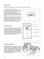
FUEL TANK
CLEAN FUEL TANK
FILLER
CAP
/
About every 100 hours of operation
or every 3
months
(whichever
comes
first),
clean the
fuel tank. Pour about a quart of clean gasoline
into tank, shake vigorously,
then empty tank
completely°
Move hose retainer
sideways
so
it will
fit through
tank
filler
oDening,
and
remove filler cap. Inspect
fuel pickup screen
for clogging.
Clean, if necessary.
.... FUEL PICKUP HOSE
i
HOSE RETAINER
FUEL PICKUP SCREEN
INSPECT COOLING
FINS
Grass particles,
chaff, dirt or grease can clog
the cooling
fins on the engine.
Continued
operation
with a clogged
cooling
system will
result
in overheating
and possible
engine
darnage.
Illustration
at right shows
blower
housing
removed
and area to be cleaned.
Inspect cooling
fins and clean, if necessary,
every 100 operating
hours°
ALL
22
CLEAN
DIRT
AREA OF
AND D_BR_S
DE-CARBONIZE
MUFFLER
Clean carbon
and condensation
from spark
arrest muffler
every 100 hours of operation.
Remove pipe plug from muffler,
Start engine
and let run for about
5 - 10 minutes.
Shut
engine
down.
When
muffler
has cooled,
reinstall
pipe plug.
Spark Arrest
Muff Jet
Hose
Clamp
Fuel Filter
REPLACE FUEL FILTER
J
Hose
P
Replace In-Line Fuel Filter every 300 hours of
operation,
or when obviously
clogged°
Use
pliers to spread
clamps
each end of filter
then slide clamps
free of filter ends. Install
new filter with arrow on filter body pointing
away from fuel tank. Retain hose to filter with
hose clampso
Start
engine
and check
for
leaks.
Replace
defective
hoses
or hose
clamps.
DE-CARBONIZE
ENGINE CYLINDER
POINT
AWAY
ARROW
ON FILTER
FROM
FUEL TANK
Fuel Tank
HEADS
Excessive carbon build-up in engine combustion
area will rob engine power and result
engine
operation.
Have carbon deposits
removed
every 300 operating
hours, more
operating
under a steady load, or whenever
cylinder
head is removed.
in rough
often
if
STORAGE
Whenever
the alternator
1o Disconnect
fuel
supply
is to be idle for longer
hose
from
fuel
tank
than
filler
30 days,
prepare
for storage
as follows:
cap.
2. Start engine and let it run out of gas°
3. Let engine coo!o
4. When engine has cooled, remove both spark plugs. Pour 2 or 3 tablespoons
into each spark plug opening°
Crank engine to distribute
oilo
5. Store unit in a clean, dry, dust-free
area_
6. Before
CHANGE
j
using unit after
OIL, Page 20.
storage,
drain
and refill
engine
crankcase
with
of clean
recommended
engine
oil
oil. See
23
Troubles
POSSIBLE
- Causes
And Remedies
CAUSE
A. ENGINE WILL NOT START OR STARTS
WITH DIFFICULTY
!
il. Out of gas
2. Fuel tank
1, Fill fuel
not vented
3. Clogged
in-line
4. Clogged
fuel
5_ Engine
fuel
spark
air cleaner
8, Gummy
deposits
B. ENGINE
LACKS
partly
2. Oil level
3. Dirty
5. Open
POWER AND/OR
closed
system
1o Open choke
2. Check
oil level
dipstick
crankcase
3. Clean
4, Improper
spark plug gap
5. Spark plug(s) defective
build-up
turn
screen
cylinder
5. Replace spark
6, Have
cylinder'
carbonized
head
- fill
to
FULL
mark
on
or' replace
4. Set gap to 0.030
in engine
cleaned
RUNS ROUGH
air cleaner
6. Carbon
one-half
choke
8, Have fuel
old gasoline
tow in engine
cap
6, Replace spark plug(s)
7. Clean or replace
dirty
from
filler
3. Replace filter
4,, Clean fuel tank filter
filter
plug
7_ Engine
t. Choke
filter
tank screen
over-choked
6o Defective
tank
2oTurn
fuel tank
counterclockwise
inch
plugs
head
removed
and
to
mark
de-
C. ENGINE RUNS HOT
1_ Lack of lubrication
2o Engine
cooling
3. Cooling
1. Check
dipstick
fins
air' flow
4o Excessive
dirty
alternator
5. Have bearing
D. LOW OR NO VOLTAGE
OUTPUT
1, Engine
bogging
of alternator
due
2o Engine
speed
3. Defective
plugged
4. Engine
plug(s)
5. Engine
cleaner
24
FROM ELECTRICAL.
tow
equipment
low
due
to defective
power
low
due
to dirty
buildup
on
air in-
replaced
OUTLETS
2= Have governor
Center
power
requires
FULL
from cooling
1o Recheck
total wattage
-total must not be more
to overloading
or shorted
electrical
into alternator
6_ Carburetor
7. Carbon
too
fill
4. Check wattage of all equipment
- total wattage should not be more than 4500 watts
bearing
down
level
2. Clean cooling
fins
3. Remove all obstructions
let and outlet
obstructed
load on engine
5o Defective
oil
adjustment
spark
engine
air
adjusted
3_ Unplug
all equipment,
device at a time to find
ed or defective
4. Replace
spark
5. Clean/replace
6. Have Sears
buretor
7o Have cylinder
of all equipment
than 4500 watts
by Sears
then plug
device that
Service
in one
is short-
plug(s)
air cleaner
Service
elements
Technician
head de-carbonized
adjust
car-
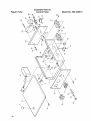
Exploded View Of
Fuel Tank
Repair Parts
Model
No. 580.326010
_L_
o_cr
_
E
._q
\
(_ m_
o 0ao.u m
__-_
25
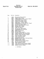
Repair
Exploded View Of
Alternator
Parts
Model
24
25
36
42
26
No. 580.326010
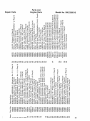
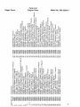
Parts List
Exploded View Of
Alternator
Repair Parts
Model
No. 580.326010
item
Part No.
Description
3
4
5
6
7
8
9
!0
11
12
13
14
t5
!6
17
18
!9
20
21
22
23
24
25
26
27
28
29
3O
31
32
33
34
35
36
37
38
39
4O
41
42
43
44
45
46
42764
22104
42775
22129
49463
24489
42776
50378
42782
42876
30332
22145
42770A
42770B
42770C
31545
24655
50396
49462
42780
42774
42875
49280
47656
43859
47665
49448
47666
49451
22237
2224"t
24049
46453
47670
23484-F
44395-E
22097
42771
30209
A-24044-A
23877-D
24488
25105
49455
49441
42343
HOUSING,
Engine Adapter (! Req'd)
PIN, Dowel (2 Req'd)
BOLT, Button
Head - 5/16-18 x 1" Long (4 Req'd)
WASHER,
Lock- 5116" (7 Req'd)
STATOR,
Ignition
(1 Req'd)
SCREW, Taptite
- No. 10-32 x 3/8" Long (4 Req'd)
KEY, Square (1 Req'd)
BRACKET,
Speed Control and Fan Guard (t Req'd)
CAPSCREW,
Hex. head (Grade 5(- 5/16-18 x 13,_,, Long (2 Req'd)
BRACKET,
Starter
Motor Support (1 Req'd)
CAPSCREW,
Hex_ Head - 5/16.,18 x 3/4" Long (7 Req'd)
WASHER,
Fiat - 5/16" (10 Req'd)
SHIM, Starter Bracket - .002" Thick (As Required)
SHIM, Starter
Bracket - .005" Thick (As Required)
SHIM, Starter
Bracket - _010" Thick (As Required)
CAPSCREW,
Hex. Head - 3/8-t6 x 31/4" Long (4 Required)
SCREW, Taptite - _A-20 x 1" Long (1 Req'd)
SPACER, (1 Req'd)
RING GEAR, with fasteners
(1 Req'd)
FAN and MAGNET ASSEMBLY
(1 Req'd)
WASHER,
Belleville
- 5/16" (1 Req'd)
SPIDER, Disc Drive (1 Req'd)
ROTOR and HUB ASSEMBLY,(1
Req'd)
HOUSING,
Alternator
Adapter (1 Req'd)
STATOR ASSEMBLY
(1 Req'd)
VIBRATION
DAMPENER
(4 Req'd)
SPACER, Vibration
Dampener
(4 Req'd)
WASHER,
Rubber (4 Req'd)
WASHER,
(4 Req'd)
WASHER,
Lock - 318" (4 Req'd)
NUT, Hex. - 3/8-16 (4 Req'd)
BEARING,
Rotor (1 Req'd)
LUG, Grounding
(1 Req'd)
CARRIER,
Rear Bearing (1 Req'd)
BUSHING,
Plastic Snap - 1" (1 Req'd)
BOLT, Stator8V2" Long (4 Req'd)
WASHER,
Lock - 1/4" (4 Req'd)
WASHER,
Fan Retaining
(1 Req'd)
CAPSCREW,
Hexo Head-5!16_24
x tl/4 '' Long (1 Req'd)
BRUSH, (2 Req'd)
HOLDER,
Brush (1 Req'd)
SCREW, Taptite - No. 8-32 x 5!8" Long (2 Req'd)
SCREW, Sims - No. 6-32 x 1,¢,, Long (2 Req'd)
COVER, Brush inspection
(1 Req'd)
SCREW, Taptite
- No_ 6.32 x 1/4" Long (1 Req'd)
BASE, Mounting
(1 Req'd)
27
Repair Parts
Exploded View Of
Sheet Metal And Accessories
Model
No. 580.326010
c_q
0
/
_0o
_O
o
CN
p..
CO
o
\
\
co
p,.
o3
LO
\
o3
\
v-
28
c'q
03
Parts List
Exploded View Of
Sheet Metal And Accessories
Repair Parts
Item
1
2
3
4
5
6
7
8
9
10
11
12
13
14
15
16
17
18
19
20
21
22
23
24
25
26
27
28
29
3O
31
32
33
34
35
36
37
38
39
4O
41
42
43
44
45
46
47
48
49
5O
51
52
53
Part No.
49421
49436
38045
49420
49437
49459
36781
22097
49457
49456
24489
49439
47672
22128
22129
22142
49413
42768
49451
22237
49472
49430
49431
49435
22507
49422
24492
25017
49229
28237
48772
42777
22259
24114
23762
22158
49445
22283
24910
46948
22145
38059
98-38078
42358
30468
42351A
49053
23897
37398
24321
42350
42451
50992
Model
No. 580.3260'10
Description
COVER, Engine (I Req'd)
GASKET, Intake Manifold
(4 Req'd)
SCREW, No. t0-32 x .37 Whiz (26 Req'd)
MANIFOLD,
Exhaust (1 Req'd)
GASKET,
Exhaust Manifold
(2 Req'd)
LINER, Exhaust
Port (2 Req'd)
BOLT, 1,,_-20 x .75 Lg, SHCS (4 Req'd)
LOCKWASHER,
1/4 (2 Req'd)
WRAPPER,
Cylinder
No. 1 (1 Req'd)
WRAPPER,
Cylinder
No. 2 (1 Req'd)
SCREW, No. t0-32 x 3t8 Taptite
(2 Req'd)
KEY, Woodruff,
3/16 x 1.00 (2 Req'd)
CARRIER,
Fan Spider (1 Req'd)
BOLl, 5/16 x 1o25 Lg. HHCS (3 Req'd)
LOCKWASHER,
5116 (15 Req'd)
BOLT, 5/16-18 x _75 Lgo HHCS (6 Req'd)
FAN, Centrifugal
12.62 Dia. (1 Req'd)
RING, Inertia (1 Req'd)
WASHER,
Fan Retainer
(1 Req'd)
LOCKWASHER,
3/8 (3 Req'd)
BOLT, 3/8-24 x 1.50 Grade 5 (1 Req'd)
COVER, Head No. 1 (1 Req'd)
COVER, Head No. 2 (1 Req'd)
BAFFLE, Engine Air (1 Req'd)
BOLT, 1/4-20 x .50 Lg. HHCS (2 Req'd)
HOUSING,
Blower (1 Req'd)
SOLENOID,
Starter Contactor
(1 Req'd)
BOLT, 3/8 x .50 Lg_ HHCS (2 Req'd)
"U" BOLT, (1 Req'd)
SADDLE, Exhaust Clamp (1 Req'd)
SPACER, Exhaust Pipe (1 Req'd)
COVER, Blower Housing
(! Req'd)
NUT, Hex. 5116-18 (4 Req'd)
NUT, Hexo 5/16-24 (2 Req'd)
LOCKWASHER,
No. 10 Shakeproof
(2 Req'd)
NUT, Hex_ 10-32 (2 Req'd)
SUPPORT,
Engine (1 Req'd)
BOLT, 5/16-18 x 1.50 HHCS (2 Req'd)
SCREW, 5116-18 x .50 Lg. Taptite (2 Req'd)
CLAMP, Exhaust Pipe (1 Req'd)
FLATWASH
ER, 5/16 (2 Req'd)
SCREW, Whiz No. 10 x 1/4 (2 Req'd)
ASSEMBLY,
Wire (1 Req'd)
STUD, Noo 10-32 x 1.00 Lg. (1 Req'd)
WASHER,
Nylon Step (1 Req'd)
LEVER, Manual Choke (1 Req'd)
WASHER,
Nylon Flat (1 Req'd)
WASHER,
No. 10 Flat (1 Req'd)
LOCK NUT, Noo 10-32 (1 Req'd)
WASHER,
No. 10 Wave (1 Req'd)
ROD, Choke Control
(1 Req'd)
BRACKET,
Muffler
Support (1 Req'd)
WASHER,
Exhaust
Flange
(4 Req'd)
29
Exploded View Of
Control Panel
Repair Parts
Model
No. 580.326010
O
C'q_
p,.
t--
P_
LO
C-q
c)
/
G)
\
\
CO
03
c_J
Pq
p..
L_
CO
03
LO
O3
03
C'q
C3
O3
30
Parts List
Exploded View Of
Control Panel
Repair Parts
item
1
2
3
4
5
6
7
8
9
10
11
12
13
14
15
16
17
18
19
20
21
22
23
24
25
26
27
28
29
++
++
++
++
Part Non
42356
24409
36918
22264
42786
42440
25034
38045
42353
22693
33868
32300
22676
22158
22152
22694
25388
23484D
43482
36933
37807
48731
49426
49474
36942
23484-C
49208
407t6
22471
47496
37806
43483
42338
Model
No. 580.326010
Description
BOX, Control
Panel (1 Req'd)
CLAMP, Cable (! Req'd)
SCREW, PPHM No. 8-32 x 1/2 Long (1 Req'd)
LOCKWASHER,
No.. 8 (1 Req'd)
REGULATOR,
Voltage (1 Req'd)
COVER, Contro_ Pane_ (I Req'd)
PLUG, Button -1o06 Dia. (1 Req'd)
SCREW, Whiz No. 10-32 x 3/8 Long (11 Req'd)
SILKSCREEN,
Panel (1 Req'd)
OUTLET, 120 Parrallel
Blade (2 Req'd)
SWITCH,
DPST (1 Req'd)
HOLDER,
Fuse (1 Req'd)
FUSE, 15A (1 Req'd)
NUT, Hex. No. !0-32 (8 Req'd)
LOCKWASHER,
No. 10 (8 Req'd)
RECEPTACLE
(2 Req'd)
RIVET, (4 Req'd)
BUSHING,
Snap (2 Req'd)
OUTLET, Twistlock
240V. 20Ao (1 Req'd)
SCREW, PPHM No. 10-32 x 3/8 (6 Req'd)
OUTLET, Twistlok
120V_ 30Ao (1 Req'd)
DIODE, Stud Mount (1 Req'd)
PANEL, Heat Sink (1 Req'd)
COIL, Ignition
(1 Req'd)
SCREW, PPHM No. 10-32 x 13/4 Long (2 Req'd)
BUSHING,
Snap (1 Req'd)
MODULE,
Ignition
(1 Req'd)
SUPPORT, _gnition Module (t Req'd)
NUT, Hex. No. 8-32 (1 Req'd)
DECAL, Warranty
(1 Req'd)
PLUG, 120 Volt, 3.Prong, 30 Amp (1 Req'd)
PLUG, 240 Volt, 4-Prong, 20 Amp (1 Req'd)
MANUAL,
Owner's
(1 Req'd)
+ + Not Shown
31
Exploded View Of
Wheel Kit And Accessories
Repair Parts
Model
No. 580.326010
o
03
04
\
o3
\
\
LO
03
CO
L_)
s
L_
O3
cJ3
p_
_3
w_
o
Dt3-
LU
fr-
O3
r_
EO
f_
_J
cc_
uJ©
_
O3
04
O
03
O30
03
o3
I-
o
('4
o3
04
Co
('4
04
LO
t--
LO
04
_2
04
03
03
r_
co
Parts List
Wheel Kit And Accessories
Repair Parts
Item
1
2
3
4
5
6
7
8
9
10
11
12
13
14
15
16
17
18
19
20
21
22
23
24
25
26
27
28
29
3O
31
32
33
34
35
Part
Nor
42343
42344
28238
28237
42346
22746
26911
47459-B
45193
28124
45900
22268
27028
22142
22145
27007
22250
22128
47466
22458
42361
29268
50543*
30288
48031-C
47662-T
47294
47662-H
25870
22097
44951
45OO0
22473
43943
46966
Model
No. 580.326010
Description
CRADLE,
(1 Req'd)
MUFFLER,(
1 Req'd)
U-BOLT, (1 Req'd)
SADDLE, (1 Req'd)
BRACKET,
Muffler (1 Req'd)
CAPSCREW,
318-16 x 1.75 Lg. Hex. Head (1 Req'd)
NUT, 3/8-16 Lock (5 Req'd)
SHAFT, (t Req'd)
SPACER, Axle (2 Req'd)
WHEEL, (2 Req'd)
WASHER,
3/4 Flat (2 Req'd)
PIN, 3/32 Cotter (2 Req'd)
NUT, 5116-18 Lock (9 Req'd)
CAPSCREW,
5/16-18 x .75 Hexo Head (2 Req'd)
WASHER,
5It6 Flat (2 Req'd)
DAMPNER,
Vibration
(1 Req'd)
WASHER,
7/16 Flat ('I Req'd)
CAPSCREW,
5116-18 x 1.25 Lg. Hex. Head (1 Req'd)
LEG, Mounting
Support (1 Req'd)
CAPSCREW,
3/8-16 x 2.75 Lg. Hexo Head (4 Req'd)
HANDLE,
Cradle (2 Req'd)
CAP, Handle (2 Req'd)
ASSEMBLY,
Fuel Tank (1 Req'd)
(Complete
w/Fittirlgs)
CONNECTOR,
Female Straight
(1 Req'd)
CLAMP, 1/4 Hose (4 Req'd)
LINE, Fuel (1 Req'd)
FILTER, Fuel (1 Req'd)
LINE, Fuel (1 Req'd)
NUT, 1A-20 Wing (2 Req'd)
WASHER,
1/4 Lock (2 Req'd)
BRACKET,
Battery Retaining
(1 Req'd)
SCREW, 1/4.20 x 7.00 Lg. Hex. Head (2 Req'd)
WASHER,
V4 Flat (2 Req'd)
STRAP, Fuel Tank Retaining
(1 Req'd)
U-BOLT, {2 Req'd)
*See
Exploded
View
of Fuel Tank,
page 25.
33
....
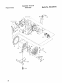
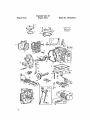
Exploded View Of
Engine Parts
Repair Parts
Model
No. 580,326010
*Special Tool
Required For
Installation
3
3
8
7
58
13
1_
16
6
20
21
19
_23
t8
39
17
._
25
26
41
3_
40
32
34
50
51
8'
34
56
b,.l_
r-
.o
o
o3
o
E
35
Exploded View Of
Engine Parts
Repair Parts
Model
No. 580.326010
!
12
2
3
4
5
8
9
10
2O
1t
27
1
3t
'
32
37
39
38
33
33
26
35 34
40
41
46
47
5O
57
6O
58
52
53
52
36
59
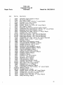
Parts List
Repair Parts
Model
Engine Parts
No. 580.326010
"o
cr
03
or"
__0___
___0__
r0
°C
0
@3
0
13..,
37
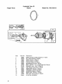
Exploded View Of
Starter
Repair Parts
Model
No. 580.326010
15
10
5
Item
38
Part
No,
Description
1
2
3
4
5
6
7
8
9
10
11
12
13
14
49462
42878
42692
42696
42693
42695
42782
22129
42870
42694
42690
42699
42691
42698
GEAR, Ring (Includes
fasteners
(1 req'd)
KtT, Pinion Spring (1 Req'd)
DRIVE, Starter (1 Req'd)
GEAR, Starter (1 Req'd)
CLUTCH,
Starter (1 Req'd)
RETAINER
and PIN (1 Req'd)
BOLT, 5/16-18 x 13/4" Long (,Grade 5) (2 Req'd)
WASHER,
Lock - 5/16" (2 Req'd)
CAP, Starter Drive End (1 Req'd)
ARMATURE,
Starter (1 Req'd)
THRU-BOLT,
Starter (2 Req'd)
HOUSING,
Starter (1 Req'd)
BRUSH SET, Starter (1 Req'd)
END CAP, Commutator
(1 Req'd)
15
50940
STARTER
ASSEM BLY
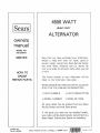
4500 WATT
HEAVY
DUTY
ALTERNATOR
owners
manual
MODEL NO.
580.3260'10
SERVICE
Now
you
have purchased
should
a need
service,
simply
and
HOW TO
ORDER
REPAIR PARTS
that
most
model
listed
on
any
Roebuck
for
of
Alternator
Alternator,
repair
parts
Sears Service
and
all pertinent
number
the
exist
contact
Sears,
sure to provide
or visit.
The
ever
your
facts
your
Co.
Center
stores,
when
Alternator
data
or
you
Be
call
will
be
plate,
WHEN ORDERING
REPAIR PARTS, ALWAYS
GIVE THE FOLLOWING
INFORMATION:
o PART NUMBER
o PART
DESCRIPTION
" MODEL
" NAME
OF ITEM
NUMBER
All parts listed may be ordered from
Service Center and most Sears stores.
If the
parts you
need are not stocked
any Sears
locally,
your order will be electronically
transmitted
to a
Sears Repair Distribution
Center for handling.
SD69420-102
PartNo. 42338GS
Sears, Roebuck and Coo, Chicago, I L 60684
Printed
U.S.A,
o
9
In U,,S,A_