1
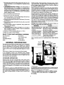
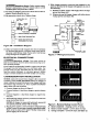
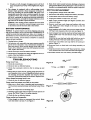
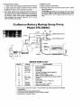
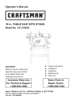
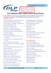
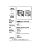
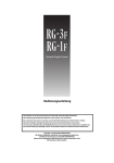
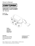
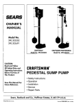
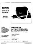
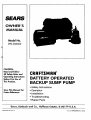
SEARS
OWNER'S
MANUAL
Model No.
390.306062
CAUTION:
Readand Follow
All SafetyRulesand
-Operating
Instructions
CRRFTSMRN"
BeforeFirstUseof
ThisProduct.
BATTERY OPERATED
BACKUP SUMP PUMP
Save ThisManual For
Future Reference.
• Safety Instructions
• Operation
• Installation
• Troubleshooting
• Repair Parts
'Sears, Roebuck and Co., Hoffman Estates, Ik 60179
PRINTED
IN
U.S.A.
U.S.A.
Form No.
F642-9510
(Rev. 5/6198)
CONTENTS
Introduction/Warranty ........................................................
2
Safety ........................................................
2
_..........................
Performance ........................................................................
3
Charger Operation ...............................................................
3
Battery Requirements ..........................................................
4
Installation/Operation
......................................................
IMPORTANT
SAFETY INSTRUCTIONS for BATTERY CHARGER
I_,WARNING[ Risk of electrical shock,
sion. Read all instructions in owner's
charger,
5_
Service/Troubleshooting
..._..............................................
6-7
Repair Parts ..........................................................................
7
2.
4.
get wet.
Use only attachments
charger manufacturer.
recommended
or sold by battery
5. When unplugging
charger, grasp plug (not cord) to avoid
risk of damage to cord or plug.
.-Ple'4_ take a few minutes to read our instructions before installing your Backup Sump Pump. It will help to assure perfect installation and help you avoid needless service
expenses.
6. Locate cord so that it cannot be stepped
damaged, stretched,
or flooded.
Do not modify cord or plug.
8.
Do not attempt
to service
charger; it has no user-serviceable parts. If charger is dropped, struck, or otherwise
damaged, take it to a qualified service technician.
FOR SAFE INSTALLATION
in this
[A
CAUTION
AND
INSTRUCTIONS
OPERATION
[CAUTION warns about hazards that will or
can cause minor personal
nored.
A This is the safety alert symbol. When you see this
symbol on your pump or in this manual, look for one of the
following signal words and be alert to the potential for personal injury!
on, tripped over,
7.
SAVE THESE
Carefully read and follow all safety instructions
manual or on pump.
using battery charger.
Charge only rechargeable
12-volt lead-acid batteries.
Other types may burst when charged with this charger.
3. Do not let charger
INTRODUCTION
RULES
before
1. Unplug battery charger before attempting
any cleaning.
Turning off controls does not reduce the risk of electrical
shock.
4-5
Electrical ...........................................................................
pump, and battery
fire, or explomanual and on
injury or property damage if ig-
The word NOTICE indicates special instructions which are
important but not related to hazards.
1.To avoid risk of serious bodily injury and property damage, read safety instructions carefully before installing
pump.
DANGER warns about hazards that will cause
serious personal injury, death or major property damage if
ignored.
2.Follow local and/or national plumbing and electrical
codes when installing pump. A ground fault circuit interrupter (GFCO is recommended for use on any electrical
appliance submerged in water.
[AW_NING]w
ING warns about hazards that can
cause serious personal injury, death or major property damage if ignored.
2
3. Use this pump only for backup sump pump duty in a residential appfication. It is not designed as a primary sump
pump.
I
h
4 la -- lHa o.
Vo ¢. Canca €
or
fatal electrical shock. Do not plug in or unplug battery
charger
while standing
on a wet floor or in water. Be sure
one hand is free when pluggingin orunplugging charger.
If basement
floor is wet, disconnect
power
to basement
before walking on floor.
lubricated at the factory. Do not try
and battery
After power is restored, charger will automatically re-charge
battery fully in about six hours.
6. Pump water only with this pump.
7. Do not run pump dry. To do so will damage seals and can
cause lealdng and property damage.
to lubricate
it!
9.Keep battery charger
---ventilated area.
box in a dry, cool, well
lO.To avoid danger of fire or explosion,
" flame away from battery.
keep
vertical
pumping
distance
sparks
and
Do not spill on
eye protection
is 15 feet.
13. Make sure sump is clear of debris.
BASIC TOOLS
AND
MATERIALS
NEEDED
Pipe Wrenches
Screwdriver
Hacksaw
1-1/4" Check
Adjustable-Wrench
Teflon Tape
Knife
12-volt Battery
GENERAL
NOTICE: Some trouble conditions will cause the alarm to
sound. See chart below for causes and action:
PROBLEM
11. [ ,AWARNING IBattery acid is corrosive.
skin, clothing, or battery charger.
Wear
when working on battery.
12. Maximum
Battery charger has capacity to run pump and charge battery
at the same time as long as power to the charger is not interrupted. If power to charger circuit is interrupted, the
length of time that the backup pump will run depends on
the Ampere-hour capacity of the battery used.
Extended periods of operation (for example, during an extended power outage) may exhaust the battery. However,
once the load is removed, usually it will self-regenerate far
enough to allow the charger to start. The battery charger will
begin charging the battery as long as the battery has a charge
of at least 1/2 volt, and power is available to the charger.
5. Do not lift pump by electrical cord,
8. Pump is permanently
If alarm sounds, check operation of primary pump, which
may need service. If battery backup operation is due to a
power outage, alarm will sound, but no service is likely to
be req_,ed to primary pump.
Valve
Back-up pump
ACTION
has run
Power out more
24 hours
Push 'Reset'.
than
Disconnect
Call power
Check main pump.
charger from battery.
company.
Continuous
charging
more than 24 hours
Disconnect
charger
Check for defective
Loose connection
or
no power to charger
Disconnect
charger from battery.
Check plug, receptacle, and
power at main breaker.
After restoring
reset.
power
or replacing
battery,
from battery.
battery.
alarm
can be
INFORMATION
The Battery-Powered
Back-up Sump Pump is not a substitute
for your primary sump pump. It is designed
as a backup
pump to pinch-hit
for your primary sump pump during a
power outage or other problem which prevents normal operation. Do not use it to pump flammable
fiquids or chemicals.
Keep
battery
charger
dry and protected
from damage.
In an emergency
(such as an extended
power
which depletes the system battery, your automobile
-may be temporarily
substituted.
Be sure to replace
tem battery as soon as possible.
CHARGER
outage)
battery
the sys-
OPERATION
Backup pump will start automatically
when sump water
level rises far enough to trip float switch. After a delay, of
about 4 seconds, alai'm will sound. Silence alarm by pushing
ALARM TEST/RESET button. In normal (switch actuated) operation, alarm is locked out until about 4 seconds after float
switch has dropped
to OFF position; cycle can then begin
again.
Test alarm by pushing
ALARM TEST/RESET
button when
alarm is not sounding. Alarm will then sound as long as button is held down. Pushing ALARM TEST/RESET button to
test alarm overrides
lockout, so alarm can be tested at any
time.
• Purchase
local.
For small/shallow
sump pits install
as illustrated
above.
Installation
Kit 2785
includes the necessary clamps and supportpad needed forthisinstallation.
Follow
other
instructions
in the owner's
manual
Figure I - Installation in small or shallow sumps
- use Kit 2785; sump diameter is exaggerated
for clarity.
TABLE
I Performance
Chart/Sears
Diehard
Size 24M
or 27M
VERTICAL
8 FEET
Battery Size
DISTANCE
FEET
12 FEET
27M
24M
27M
24M
27M
24M
Gallons Per Minute
18.0
18.0
14.5
14.5
11.5
11.5
Hours Available
9.6
8.3
9.9
8.3
6.8
5.7
Total Gallons Pumped
7,212
6,055
5,557
4,939
3,727
3,189
BATTERY
--
10
PUMPING
REQUIREMENTS
IAkWARNING IHazardous
electrical
current.
Can cause se-
vere burns and start a fire if battery terminals
are short circuited. Install battery in box. To prevent accidental
shorting
across battery terminals, strap cover securely on battery box.
Do not leave battery uncovered.
Do not allow children
to
;-play around sump pump installation.
Your Backup Sump Pump depends on the battery used with
it for power.
The better the battery, the better the performance of the pump. We recommend use of a SEARS DieHard
Size 27M or 24M Deep-Cycle
Marine battery. This battery
will perform well for many hours and stands up well to long
periods of little or no use.
In an emergency
a SEARS DieHard Size 27M or 24M standard
automobile
battery may be used. However,
an automotive
battery may require charging after only 1 to 2 hours of continuous
use, and the repeated charging
cycles may cause
early plate failure in the battery.
Use ordy a new, fully charged battery that will fit in the battery-box.(maximum
size 12-5/8" long, 7" wide and 9-3/8"
high including terminals).
PU M P I NSTALLATION
and OPERATION
down
5. Cut rigid discharge
pipe from primary sump pump to
length. Use PVC piping. Tee supplied is 1-1/2" slip fit; if
necessary use 1-1/4" bushings supplied.
NOTICE: Use any tee that fits sump pump discharge line;
the adapter that is supplied (Key No. 10, Page 7) will fit
any galvanized
or plastic 1-1/4" tee. Do not glue the tee
until all parts have been trial fitted.
6.Thread
adapter
into tee (Figure
molded-in 'up' should be on top.
7.Install backup
backup
pump
adapter.
pump
check
check
valve
2B). When
installed,
valve in adapter.
fits into notchat
Tab on
top of
8. For trial assembly,
slip pump into backup pump check
valve to check pump mounting
height and to make sure
that there is no interference
with float switch operation
on either pump; be sure floats will not rub on side of
sump, catch between
pump and sump wall, interfere
with each other, etc.
9. Remove
NOTICE:
We recommend
a trial fitting of all components
before gluing anything. This will allow you to check pump
mounting
height, float switch clearance,
etc., while adjustments can still be easily made.
1 .Mark side of sump six inches
How through this check valve must be away from the
main sump pump; don't install it backwards!
This
check valve will prevent recirculation
into the sump
during battery-powered
pump operation.
pump
from adapter;
lO.Using PVC glue, permanently
sump pump discharge pipe.
remove
tee.
reinstall
tee in primary
from top.
2. Fill sump until primary sump pump starts; normal high
water level should not be above mark made in step 1. If
it is higher, backup float switch may not swing far enough
for proper operation.
To lower high water level, adjust
switch
on primary
sump pump.
See primary
pump
Grounded
Electrical
Outlet
owner's manual.
3. Drain sump. Measure down 11 inches from top of sump;
mark this point on side of sump. Install tee with center of
threaded inlet at least this far below top of sump to allow
sufficient room for float switch to swing (see Figure 2A).
4. Make sure that installation will not interfere
sump pump operation
as follows:
6" Min.
t
11" Min.
(279mm)
(152mm)
with primary
A. Backup pump installation must not interfere
mary sump pump float switch swing.
with
pri-
B. Normal high water level must never be high enough
to start backup sump pump.
C. Install a check valve (SEARS Stock No. 2789) in the
main sump pump discharge pipe between
the pump
and the backup mounting tee (see Figures 2A and 2B).
13801194
Figure ZA - Standard
Installation
[AWARNING[Hazardous
fumes. Follow cement manufacturer's instructions. Use PVC cement only in a well
ventilated place away from fire or flame.
3. With charger
properly
connected
and plugged in, the
panel on the front of the charger will appear as in one of
the following:
A.
11.Put clamp on adapter;, leave loose. Mount check valve in
adapter; thread ag_nbly into tee.
If battery is dead, charger
"power (see Figure 4A).
will supply
B. If battery is near full charge, charger
5 amps power (see Figure 4B).
12.Slip pump into check valve. Tighten clamp.
about
10 amps
will deliver about
1-1/2x1-1/2x1-1/4
Black
L__JZ
5 /Tee" PVC
/
/
Pipe
Check
_/
,r ValveC: ]
Brown
[_-l,q_--
ReducerBushing(2 Supplied)
Batten# Clamp
r---ll
.@_-_-
Main PumpDischargePipe
Positive
(Black Iv/
Red Tracer)
_---,_
i *':_
j, l'€-I
L.... J
I
u
Check
Valve to
Prevent
Recirculation
intoSump
I
Black
Figure 2B - Installation
Diagram
13. Make sure battery is fully charged; then check operation
by disconnecting
power to primary sump pump and filling sump until Backup Sump Pump starts. Run Backup
Pump through one complete
cycle.
ELECTRICAL
voltage.
shock. Review
charger.
If your outlet is not grounded,
14 gauge) from the outlet
ground clamp on pipe. BE
used has metal continuity
charger is double insulated.
NOTICE: Alarm
to battery. Press
alarm continues
-the battery and
again; alarm will
1. Connect
Can
cause
safety instructions,
Connections
serious
or
Page 2, be-
install a copper wire (at least
box to a cold water pipe. Use
SURE that the cold water pipe
to electrical
ground.
Battery
DO NOT modify cord or plug.
CHARGER/BATTERY
A. Connect
post.
Figure 3 - Wiring
CONNECTIONS
I AWARNINGIE[aZardous
fatal electrical
fore operating
1411 1104
A.
INSTALLATION
will sound when charger is first connected
ALARM TEST/RESET button on charger. If
to sound, disconnect
one charger lead from
reconnect
it. Press ALARM TEST/RESET
stop sounding.
charger
as shown
in Figure
3.
Positive (+) lead from charger
B. Connect Negative (-) lead from charger
tery post.
".....
C. Third lead from c lMa'ger is factory
pump motor/float
switch.
BD
to positive
battery
to negative
connected
NOTICE: If charger is connected
backwards,
not operate properly, battery will not charge.
bat-
to lead from
CI
1413 1194
pump will
2. Plug in power cord to a 115-125 Volt AC outlet delivering
at least 2 amps. Do not use a switch controlled
outlet.
Mark circuit in main power panel =Backup sump pump
power supply; do not turn off'.
Figure 4 - Battery
/L
B.
C.
Backup Control
Panel
Battery depleted - charging current 10 amps.
Battery nearly charged - current about 5 amps.
Charge complete - current 0 amps, LED lights up.
C.
If battery is fully charged, charging current will be 0
amps and green LED lamp will be lighted (see Figure
4C).
2. Main check valve located between
discharge of primary
pump and the Backup Sump Pump tee or check valve not
installed or working properly. Install or repair as required.
4. The charger is equipped
with a self-resetting
circuit
breaker whi_ch protects it from temporary overloads. In
case of an overload,
the circuit breaker will open. It automatically resets after a short cool-down period. In some
conditions
where the overload is extended
the breaker
will cycle, repeating the open/reset
process indefinitely.
When this happens, normally the charger will emit a clicking sound as the breaker opens and resets.
SWITCH
1. Unplug battery
2. Disconnect
1. Unplug
battery
as follows
to maintain
electrolyte
5. Plug in battery
fuse holder
10. Remount
pump.
that
automatic
battery.
switch
is free to swing
up and
4. Blown fuse in switch circuit. Unplug pump and check to
see if impeller is free to turn. If impeller is locked, remove
the housing
around the impeller
and remove the obstruction. Reassemble pump and reconnect.
Replace fuse.
Pump
but pump
won't
for low or defective
runs but
pumps
run:
Figure 6
battery.
very little
or no water:
1. Make sure a check valve is installed and functioning
between primary pump discharge and Backup Sump Pump
tee.
".....
2. Check
for obstruction
in discharge
4. Check
for low or defective
cycles
Figure 7
pipe.
3. Discharge pipe length and/or height exceeds capacity
pump. See Table I, Page 4, for pump capacity.
Pump
on band
and
snap
and cord
wire onto battery
--'_t
Figure 5
3. Check
down.
hums
block
12. Bolt black switch
and cor-
Pump won't run.
1. Check all connections.
1. Check
(see Figure 2) before
charger.
for low or defective
of
battery.
too frequently:
1. Tether length too short on automatic float switch.
sure that tether is at least 2n; see Figure 2.
clamp.
loos-
with new
as the old
half which you are inhalf on pump wire.
halves
of housing
to-
assembly
on
clamp
11. Strip black switch wire back 3/8" from end of wire. Crimp
wire terminal onto end of wire and check for tightness.
level and refill as needed.
2. Check
terminals.
wire; save fuse.
length
9. Insert fuse into holder
gether (Figure 7).
TROUBLESHOOTING
Motor
wire from battery
in white
NOTICE: Be sure that fuse holder
stalling will mate with fuse holder
charger.
4. Check battery terminals and clamps for tightness
.... _rosion_: Clean and tighten as needed.
black switch
4. Unplug
from battery
8. Insert stripped wire end in small end of fuse holder half;
crimp holder onto wire and check crimp for tightness
(Figure 6).
2. On batteries with removable
top caps, measure specific
gravity of the electrolyte.
Use a hydrometer
(available at
auto parts stores). If the specific gravity of any cell is less
than 1.225 or if there is more than .050 variation between
cells, replace the battery.
3. Check
3. Unbolt
clamps
7. Strip insulation off of white wire on new switch, leaving
3/8" bare wire exposed at the wire end (see Figure 5).
NOTICE: To protect battery case from chipping
and goug:--ing,.do not let battery sit on concrete floor. Install battery on
a shell or protective
pad (plywood,
2x4s, etc.). Always irv
stall battery in a dry location that is protected
from flooding.
battery
from wall outlet.
6. Remove
cord from cord clamp and replace
cord. Make sure tether length is the same
switch's tether.
MAINTENANCE
Every three months,
check
battery in best condition:
charger
both battery
5. Make a note of tether
ening cord clamp.
NOTICE: If the clicking sound continues
for more than
30 minutes or so, check for reversed charger connections
to the battery and for shorted cells in the battery.
BATTERY
REPLACEMENT
Figure 8
Make
6
t-_--3/8"
terminal
clamp.
13. Reinstall
battery
A. Black switch
B. Black pump
NOTICE:
clamps:
15. Replace
wire damps
wire clamps
DO NOT reverse
to positive
battery
to negative
terminal
battery
terminal.
16.Plug
terminal.
17.Fill sump with water
tether if necessary.
connections.
in charger
to wall outlet.
and check
switch
action.
IDONOT
Battery Backup Sump Pump
Model 390.306062
6A
6B
Battery Clamp
Brown
y Clamp
12
/
Negative
1412 1194
REPAIR
Key No.
1
2
3
4
5
6A
6B
7
8
9
10
11
12
#
*
**
***
1
Part No.
PS217-5E
PS17-41
CC0030-13
U17-1148
U17-1149
PS17-100
PS 117-77A
PS22-1
PS78-3P
U78-846P
U78-876P
Adjust
IA CAUTION
test run pump for more than
5 seconds
without
water in it. Running pump dry for
extended
periods
could damage pump and voids warranty.
14.Turn pump upside down; unclip and remove screen. Do
not remove screw-mounted
bottom plate. Lift switch to
momentarily
"bump _ pump. Check for correct operation
and rotation (pump
must rotate counter-clockwise
when looking at end of shaft - Figure 8). If not, reverse
wires to battery and recheck.
Craftsman
screen.
PARTS LIST
Part Description
SwitchAssembly#
PumpComplete***
CordClamp
Fuse Holder
15-AmpTime-DelayFuse(2 suppliedt)
WireTerminal(4 Req.)
BatteryTerminalClamps(2 Req.)
BatteryCase (includesstrapand strapbrackets)
.Charger***
CheckValve
Hose Clamp1"min.- 2"max.S.S.
PipeAdapter
Tee 1-1/2x 1-1/2x 1-1/4 PVC
ReducerBushing(2 Red.)
When ordering,also orderKeyNos. 4 (Fuse Holder)and 5 (Fuse) required for installation.
Not illustrated.
StandardHardwareItem;purchaselocally.
No componentpartsavailablefor pumpor batterycharger.
Secondfuse issuppliedas spare.
SEAI?S
OWNER'S
MANUAL
CRAFTSMRN°
BATTERY OPERATED
BACKUP SUMP PUMP
Model No.
390.306062
Forthe repair or replacementparts you need
Call 7 am - 7 pm, 7 days a week
1-800-366-PART
(1-800-366-7278)
Forin-homemajorbrandrepair service
Call24 hoursa day, 7 daysa week
The model number of
1-800-4-REPAIR
(1-800-473-7247)
your Backup Sump Pump
will be located on the
pump, not the battery
charger.
When requesting service
or ordering parts, always
give the following
information:
• Product Type
• Model Number
• Part Number
• Part Description
Forthe location of a
SearsRepairServiceCenterin yourarea
Call 24 hoursa day,7 days a week
1-800-488-1222
I|BB||
Forinformationon purchasinga Sears
MaintenanceAgreementor to Inquire
aboutan existingAgreement
callg am - 5 pro,Monday-Saturday
....1-800-827-6655
SF.4RS
+t4r_.,
rl;l,'y=flql+,i
_
_- Sears, Roebuck and Co., Hoffman EstatesTIL 60179
U.S.A.