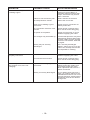
1
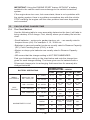
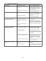
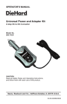
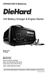
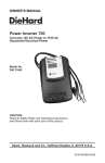
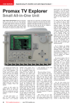
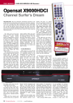
OPERATOR’S MANUAL
®
BATTERY CHARGER
70/40/20/4 Amp
300 AMP
ENGINE STARTER
With Battery Tester
Model No.
200.71991
CAUTION:
Read and follow all Safety
Rules and Operating Instructions
Before Every Use of this Product.
Save these instructions.
Sears, Roebuck and Co., Hoffman Estates, IL 60179 U.S.A.
00-99-000882/0808
Table of Contents
SECTION
Page
1. IMPORTANT SAFETY INSTRUCTIONS
1
2. personal precautions
2
3. preparing to charge 3
4. charger location
3
5. dc connection precautions
3
6. when battery is installed in vehicle 4
7. when battery is outside vehicle 5
8. battery charging - ac connections
6
9. product features
8
10. assembly instructions
8
11. operating instructions
10
12. engine start
11
13. calculating charge time
12
14. maintenance instructions
14
15. storage instructions
14
16. troubleshooting
14
DieHard Three-Year Full Warranty
When operated and maintained according to all supplied instructions,
if this DieHard product fails due to a defect in material or workmanship
within one year from the date of purchase, return it to any Sears store
or other DieHard outlet in the United States for free replacement.
This warranty does not include fuses, which are expendable parts.
This warranty gives you specific legal rights, and you may also have
other rights which vary from state to state.
Sears, Roebuck and Co., Hoffman Estates, IL 60179
For customer assistance or replacement parts,
call toll-free from 7 am to 4:30 pm CT
Monday through Friday: 1-800-SEARS-64 (1-800-732-7764)
IMPORTANT: read and save this safety and instruction manual.
1.
IMPORTANT SAFETY INSTRUCTIONS
1.1
SAVE THESE INSTRUCTIONS - The DieHard model 71991 Manual Battery Charger, offers a wide range of features to accommodate the needs
for home or light commercial use. This manual will show you how to use
your charger safely and effectively. Please read and follow these instructions and precautions carefully as this manual contains important safety
and operating instructions.
1.2
Do not expose charger to rain or snow.
1.3
Use of an attachment not recommended or sold by the battery charger
manufacturer may result in a risk of fire, electric shock or injury to persons.
1.4
To reduce the risk of damage to electric plug or cord, pull by the plug
rather than the cord when disconnecting the charger.
1.5
An extension cord should not be used unless absolutely necessary. Use of
an improper extension cord could result in a risk of fire and electric shock.
If an extension cord must be used, make sure:
• That the pins on the plug of the extension cord are the same number,
size and shape as those of the plug on the charger.
• That the extension cord is properly wired and in good electrical condition
and;
• That the wire size is large enough for the AC ampere rating of the charger
as specified in Table 8.2.
1.6
Do not operate the charger with a damaged cord or plug; take it to a qualified serviceman. (Call customer service at: 800-SEARS-64).
1.7
Do not operate the charger if it has received a sharp blow, been dropped
or otherwise damaged in any way; take it to a qualified serviceman. (Call
customer service at: 800-SEARS-64).
1.8
DO NOT attempt to repair product yourself. To arrange for product repair,
or for information about customer replaceable parts, call 1-800-SEARS-64
(1-800-732-7764).
1.9
In case of charger malfunction, DO NOT attempt to repair the charger
yourself. To arrange for charger repair, or for information about customer
replaceable parts, call 1-800-SEARS-64 (1-800-732-7764)
1.10 Do not disassemble the charger; take it to a qualified serviceman when
service or repair is required. Incorrect reassembly may result in a risk of
electric shock or fire. (Call customer service at: 800-SEARS-64).
1.11 To reduce the risk of electric shock, unplug the charger from the outlet
before attempting any maintenance or cleaning. Turning off the controls
will not reduce this risk.
1.12 WARNING: Pursuant to California Proposition 65, this product contains
chemicals known to the State of California to cause cancer and birth defects or other reproductive harm.
•1•
WARNING – RISK OF EXPLOSIVE GASES.
WORKING IN THE VICINITY OF A LEAD-ACID BATTERY IS DANGEROUS. BATTERIES GENERATE EXPLOSIVE GASES DURING NORMAL BATTERY OPERATION. FOR THIS REASON, IT IS OF UTMOST
IMPORTANCE THAT YOU FOLLOW THE INSTRUCTIONS EACH TIME
YOU USE THE CHARGER.
TO REDUCE THE RISK OF BATTERY EXPLOSION, FOLLOW THESE
INSTRUCTIONS AND THOSE PUBLISHED BY THE BATTERY MANUFACTURER AND THE MANUFACTURER OF ANY EQUIPMENT YOU
INTEND TO USE IN THE VICINITY OF THE BATTERY. REVIEW THE
CAUTIONARY MARKINGS ON THESE PRODUCTS AND ON THE
ENGINE.
2.
PERSONAL PRECAUTIONS
2.1
Consider having someone close enough by to come to your aid when you
work near a lead-acid battery.
2.2
Have plenty of fresh water and soap nearby in case battery acid contacts
your skin, clothing or eyes.
2.3
Wear complete eye protection and clothing protection. Avoid touching your
eyes while working near the battery.
2.4
If battery acid contacts your skin or clothing, wash immediately with soap
and water. If acid enters your eye, immediately flood the eye with cold running water for at least 10 minutes and get medical attention immediately.
2.5
NEVER smoke or allow a spark or flame in the vicinity of a battery or
engine.
2.6
Be extra cautious to reduce the risk of dropping a metal tool onto the battery. It might spark or short-circuit the battery or other electrical part that
may cause an explosion.
2.7
Remove personal metal items such as rings, bracelets, necklaces and
watches when working with a lead-acid battery. A lead-acid battery can
produce a short-circuit current high enough to weld a ring or the like to
metal, causing a severe burn.
2.8
Use this charger for charging a LEAD-ACID battery only. It is not intended
to supply power to a low voltage electrical system other than in a startermotor application. Do not use this battery charger for charging dry-cell
batteries that are commonly used with home appliances. These batteries
may burst and cause injury to persons and damage to property.
2.9
NEVER charge a frozen battery.
2.10 WARNING: Pursuant to California Proposition 65, this product contains
chemicals known to the State of California to cause cancer and birth defects or other reproductive harm.
•2•
3.
PREPARING TO CHARGE
3.1
If it is necessary to remove the battery from the vehicle to charge it, always remove the grounded terminal from the battery first. Make sure all of
the accessories in the vehicle are off, so as not to cause an arc.
3.2
Be sure the area around the battery is well ventilated while the battery is
being charged.
3.3
Clean the battery terminals. Be careful to keep corrosion from coming into
contact with your eyes.
3.4
Add distilled water to each cell until the battery acid reaches the level
specified by the battery manufacturer. Do not overfill. For a battery without
removable cell caps, such as valve regulated lead-acid batteries, carefully
follow the manufacturer’s recharging instructions.
3.5
Study all of the battery manufacturer’s specific precautions while charging
and recommended rates of charge.
3.6
Determine the voltage of the battery by referring to the vehicle owner’s
manual and make sure that the output voltage selector switch is set to the
correct voltage. If the charger has an adjustable charge rate, charge the
battery at the lowest rate first.
4.
CHARGER LOCATION
4.1
Locate the charger as far away from the battery as the DC cables permit.
4.2
Never place the charger directly above the battery being charged; gases
from the battery will corrode and damage the charger.
4.3
Never allow battery acid to drip onto the charger when reading the electrolyte specific gravity or filling the battery.
4.4
Do not operate the charger in a closed-in area or restrict the ventilation in
any way.
4.5
Do not set a battery on top of the charger.
5.
DC CONNECTION PRECAUTIONS
5.1
Connect and disconnect the DC output clips only after setting all of the
charger switches to the “off” position and removing the AC plug from the
electrical outlet. Never allow the clips to touch each other.
5.2
Attach the clips to the battery and chassis, as indicated in steps 6.5, 6.6,
and 7.2 through 7.4.
•3•
6.
FOLLOW THESE STEPS WHEN BATTERY IS INSTALLED IN vehicle
A SPARK NEAR BATTERY MAY CAUSE BATTERY EXPLOSION. TO
REDUCE RISK OF A SPARK NEAR BATTERY:
NEGATIVE GROUNDED SYSTEM
6.1
Position the AC and DC cables to reduce the risk of damage by the hood,
door, or moving engine parts.
6.2
Stay clear of fan blades, belts, pulleys and other parts that can cause
injury.
6.3
Check the polarity of the battery posts. The POSITIVE (POS, P, +) battery
post usually has a larger diameter than the NEGATIVE (NEG, N, -) post.
6.4
Determine which post of the battery is grounded (connected) to the chassis. If the negative post is grounded to the chassis (as in most vehicles),
see step 6.5. If the positive post is grounded to the chassis, see step 6.6.
6.5
For a negative-grounded vehicle, connect the POSITIVE (RED) clip from
the battery charger to the POSITIVE (POS, P, +) ungrounded post of the
battery. Connect the NEGATIVE (BLACK) clip to the vehicle chassis or
engine block away from the battery. Do not connect the clip to the carburetor, fuel lines or sheet-metal body parts. Connect to a heavy gauge metal
part of the frame or engine block.
6.6
For a positive-grounded vehicle, connect the NEGATIVE (BLACK) clip
from the battery charger to the NEGATIVE (NEG, N, -) ungrounded post
of the battery. Connect the POSITIVE (RED) clip to the vehicle chassis or
engine block away from the battery. Do not connect the clip to the carburetor, fuel lines or sheet-metal body parts. Connect to a heavy gauge metal
part of the frame or engine block.
6.7
When disconnecting the charger, turn all switches to off, disconnect the
AC cord, remove the clip from the vehicle chassis, and then remove the
clip from the battery terminal.
6.8
See OPERATING INSTRUCTIONS for length of charge information.
•4•
7.
FOLLOW THESE STEPS WHEN BATTERY IS OUTSIDE VEHICLE.
A SPARK NEAR THE BATTERY MAY CAUSE BATTERY EXPLOSION.
TO REDUCE RISK OF A SPARK NEAR BATTERY:
7.1
Check the polarity of the battery posts. The POSITIVE (POS, P, +) battery
post usually has a larger diameter than the NEGATIVE (NEG, N, -) post.
7.2
Attach at least a 24-inch-long 6-gauge (AWG) insulated battery cable to
the NEGATIVE (NEG, N, -) battery post.
7.3
Connect the POSITIVE (RED) charger clip to the POSITIVE (POS, P, +)
post of the battery.
7.4
Position yourself and the free end of the cable you previously attached to
the NEGATIVE (NEG, N, -) battery post as far away from the battery as
possible – then connect the NEGATIVE (BLACK) charger clip to the free
end of the cable.
7.5
Do not face the battery when making the final connection.
7.6
When disconnecting the charger, always do so in reverse sequence of
the connecting procedure and break the first connection while as far away
from the battery as practical.
7.7
A marine (boat) battery must be removed and charged on shore. To
charge it onboard requires equipment specially designed for marine use.
•5•
8.
8.1
battery charging - ac connections
GROUNDING AND AC POWER CORD CONNECTION
INSTRUCTIONS – Charger should be grounded to reduce risk of electric
shock. Charger is equipped with an electric cord having an equipmentgrounding conductor and a grounding plug. The plug must be plugged
into an outlet that is properly installed and grounded in accordance with
all local codes and ordinances.
DANGER – Never alter the AC cord or plug provided - if it will not fit the
outlet, have the proper outlet installed by a qualified electrician. An improper connection can result in a risk of an electric shock.
This battery charger is for use on a nominal 120-volt circuit, and has a
grounding plug that looks like the plug illustrated in sketch A in Figure 8.3.
A temporary adapter, which looks like the adapter illustrated in sketches
B and C, may be used to connect this plug to a two-pole receptacle as
shown in sketch B if a properly grounded outlet is not available. The temporary adapter should be used only until a properly grounded outlet can
be installed by a qualified electrician.
DANGER – Before using adapter as illustrated, be certain that center
screw of outlet plate is grounded. The green-colored rigid ear or lug ex
tending from adapter must be connected to a properly grounded outlet–
make certain it is grounded. If necessary, replace original outlet cover
plate screw with a longer screw that will secure adapter ear or lug to
outlet cover plate and make ground connection to grounded outlet.
•6•
8.2
Recommended minimum AWG size for extension cords for battery
chargers:
AC input rating,
a
amperes
But less
At least
than
0
2
2
3
3
4
4
5
5
6
6
8
8
10
10
12
12
14
14
16
16
18
18
20
25
(7.6)
18
18
18
18
18
18
18
16
16
16
14
14
AWG size of cord
Length of cord, feet (m)
50
100
150
(15.2)
(30.5)
(45.6)
18
18
16
18
16
14
18
16
14
18
14
12
16
14
12
16
12
10
14
12
10
14
10
8
12
10
8
12
10
8
12
8
8
12
8
6
a
If the input rating of a charger is given in watts rather than in
amperes, the corresponding ampere rating is to be determined
by dividing the wattage rating by the voltage rating ± for
example:
1250 watts/125 volts = 10 amperes
8.3
Grounding Methods
•7•
9.
features
3
4
5
2
6
1
7
8
1. Ammeter
2. Volt Meter
3. Foam Grip
4. Fiber Glass Clamp Rod
5. Clamps
6. Charge Rate Selector Switch
7. Timer
8. Wheel
10. assembly instructions
It is important to fully assemble your charger before
use. Follow these instructions for assembly:
ITEM QTY
NO.
DESCRIPTION
1
2
axle bracket
2
1
axle with pin holes
3
2
wheel
4
2
screw, 10-32 x 1/2, self tapping
5
2
screw, 1/4-20 x 3/4, self tapping
6
1
wheel charger foot
7
2
hubcap, black
8
2
hairpin cotter
9
2
nylon washer
10
4
screw, 8-18 x 1/2 sheet metal
11
1
handle assembly
12
1
fiberglass clamp rod
13
1
foam handle grip
TOOLS NEEDED
•8•
5/16” Wrench or Nut Driver
3/8” Wrench or Nut Driver
Screwdriver (Flat Blade)
Screwdriver (Phillips)
Hammer
10.1 First, carefully lay the charger on its front to prepare for assembly.
10.2 Assemble the foot (Item 6) using two ¼-20 screws (Item 5) and tighten
securely.
10.3 Attach the two axle brackets (Item 1) using one 10-32 screw (Item 4) in
each. The brackets should have one end hooked into the slot in the charger base. (Do not completely tighten the screws (Item 4) at this time).
10.4 Slide the axle (Item 2) into the brackets (Item 1) until centered on the charger.
10.5 Slide one wheel (Item 3) onto the axle with the recessed hub facing out as
shown.
10.6 Next insert pin (Item 8) thru axle hole.
10.7 Repeat this process for the other wheel and when both wheels have been
pinned to axle, finish tightening the two axle bracket screws (Item 4).
10.8 Snap hub caps (Item 7) onto each wheel to cover the pin and axle.
10.9 Next lift the charger upright so that it rests on the wheels and foot.
10.10 Remove the two top side screws (Item 9) from each side of the charger.
10.11 Verify that the foam handle grip (Item 12) is on the handle assembly (Item
10), install if needed.
10.12 Insert the fiberglass clamp rod (Item 11) into the pierced holes on the
inside of the handle (Item 10).
10.13 Align the handle assembly (Item 10) with charger and reinstall the side
screws (Item 9). Do not over tighten.
10.14 Charger assembly is now complete. Battery clips can be clamped to the
fiberglass rod (Item 11) for convenient storage.
10.15 Do not attach clips to the foam area of handle as this will damage the
foam grip.
•9•
11.
operating instructions
11.1 TIMER
The main function of the timer is to prevent over charging while allowing a
battery time to obtain a satisfactory charge. To properly set the timer you
must know the size of the battery in ampere hours or reserve capacity in
minutes and the state of charge. Often the state of charge is not known,
this is one reason why the timer was limited to 2.25 hours. With the aid
of a battery load tester the state of charge can be obtained within a few
seconds. For example, the average size automotive battery at a 50%
state of charge will require 1 to 1.5 hours of charging at the 40 amp rate
to reach the full charge state. For the same battery with the timer set to its
maximum, 2.25 hours, over charging will occur, but not likely cause harm
to a battery that was otherwise in good condition. When the charge state
is not known, start out with a timer setting of one hour or less, or use the
automatic setting.
11.2 HOLD
This position defeats the timer function, allowing for continuous operation.
AUTOMATIC MODES: Put the timer in the HOLD position when the battery charger is in one of the automatic modes, otherwise the timer will shut
the charger off when the set time expires regardless of whether the charge
is complete or not. The green “charged” LED will light and the fan will shut
off when the charging is complete.
MANUAL MODES: Use when you want to charge more than 2.25 hours.
Be sure to monitor the charging procedure and stop it when the battery is
charged. Not doing so may cause damage to your battery.
11.3 AMP RATE SELECTOR SWITCH
Use the amp selector switch to select the charge rate or engine starting
setting you require.
• 10 •
11.4 AMMETER
The Ammeter indicates the amount of current measured in amperes that
is being drawn by the battery. For example, in the 40 amp charge rate a
typical discharged battery will initially draw approximately 40 amps. As
the battery continues to charge, current will taper to 15 to 20 amps at full
charge. The Start area of the meter indicates a high rate of current being drawn from the charger. When cranking an engine, the starter motor
draws upwards to 200-300 amps. The meter needle will be at the extreme
right side of the start area. Sometimes a battery for the first few minutes
of its charge will draw more than 70 amps, in this case the needle may
be within, but not all the way over, to the right side of the start area. The 4
amp charge rate may indicate some activity on the meter. The meter does
not have the resolution to display this low rate.
11.5 VOLTMETER
The Voltmeter indicates the voltage at the battery terminals. Use as follows:
1. The charger need not be plugged into an AC outlet. The timer should
be in the OFF position. Then connect the charger following instructions
in Sections 6 and 7.
2. Observe the meter indication. Keep in mind that this reading is only a
battery voltage reading, a false surface charge may mislead you. We
suggest that you turn on your headlights for a couple of minutes before
you read the meter. Read a couple of minutes after you have shut the
headlights off. If the reading is less than 10.5-volts, the battery may be
bad or the connections at the charger may be poor. If the reading is
10.5-volts to 12.8-volts the battery is low – recharge it. If the reading is
above 12.8-volts the battery is charged.
12. engine start
12.1 Set the charge rate switch and the timer to the OFF positions.
12.2 With the charger unplugged from the AC outlet, connect the charger to the
battery following instructions given in section 6.
12.3 Plug the charger AC power cord into the AC outlet, and then move the
timer from OFF to the HOLD position.
12.4 Set the amp rate selector switch to the engine start position and then
crank the engine until it starts or 5 seconds passes.
NOTE: During extremely cold weather, or if the battery is under 2 volts,
charge the battery for five minutes before cranking the engine.
12.5 If the engine fails to start, charge the battery for 5 more minutes before
attempting to crank the engine again.
12.6 After the engine starts, move the amp rate selector switch to OFF and
unplug the AC power cord from the outlet before disconnecting the battery
clamps.
• 11 •
IMPORTANT: Using the ENGINE START feature WITHOUT a battery
installed in the vehicle could cause damage to the vehicle’s electrical
system.
If the engine does turn over, but never starts, there is not a problem with
the starting system; there is a problem somewhere else with the vehicle.
STOP cranking the engine until the other problem has been diagnosed
and corrected.
13. calculating charge time
13.1 The Chart Method
Use the following table to more accurately determine the time it will take to
bring a battery to full charge. First, identify where your battery fits into the
chart.
• Small batteries – motorcycle, garden tractors, etc. – are usually rated in
Ampere Hours (AH). For example: 6, 12, 32 AH etc.
• Batteries in cars and smaller trucks are usually rated in Reserve Capacity
(RC), Cold-Cranking Amps (CCA), or both.
• Marine or deep-cycle batteries are usually rated in Reserve Capacity
(RC).
• NR means that the charger setting is NOT RECOMMENDED.
Find your batteries rating on the chart below and note the charge time
given for each charger setting. The times given are for batteries with a
50-percent charge prior to recharging. Add more time for severely discharged batteries.
CHARGE RATE/
CHARGING TIME - HOURS
BATTERY SIZE/RATING
SMALL
BATTERIES
CAR/
TRUCKS
4 AMP
20 AMP
40 AMP
70 AMP
6 - 12 AH
2-4
NR
NR
NR
12 - 32 AH
4 - 10
NR
NR
NR
200 - 315 CCA
40 - 60 RC
11 - 14
60 - 90
min.
30 - 40
min.
20 - 30
min.
315 - 550 CCA
60 - 85 RC
14 - 18
90 - 120
min.
45 min 1 hr
30 - 40
min.
550 - 1000 CCA
85 - 190 RC
18 - 35
2 - 3.5
hrs.
1 - 2 hr
45 - 60
min.
80 RC
18
105 min.
1 hr
NR
140 RC
27
2 hrs., 45
min.
1 hr and
15 min
NR
160 RC
30
3 hrs.
1.5 hrs
NR
180 RC
33
3.5 hrs.
2 hrs
NR
Motorcycle, garden, tractor, etc.
MARINE/DEEP CYCLE
• 12 •
13.2 The Hydrometer or Electronic Method
To find the time needed to fully charge your battery, determine the battery’s charge level with a hydrometer or electronic Percent-of-Charge
Tester. The following table will help you convert hydrometer readings to
percent of charge values.
SPECIFIC GRAVITY
OF CHARGE
PERCENT OF CHARGE PERCENT
NEEDED
1.265
100%
0%
1.225
75%
25%
1.155
25%
75%
1.120
0%
100%
When you know the percent of charge and the Amp Hour (AH) rating of
your battery, you can calculate the approximate time needed to bring your
battery to a full charge.
To convert Reserve Capacity to Amp Hours, divide Reserve Capacity by
2, and add 16:
Amp Hours = Reserve Capacity + 16
2
NOTE: The Reserve Capacity can be obtained from the battery specification sheet or the owner’s manual.
To calculate time needed for a charge:
• Find the percent charge needed. (A battery at 50 percent charge that will
be charged to 100 percent needs another 50 percent (.50)).
• Multiply the Amp Hour rating by the charge needed (.50) and divide by
the charger setting (2, 15, or 60 amps).
• Multiply the results by 1.25 and you will have the total time needed, in
hours, to bring the battery to full charge.
• Add one additional hour for a deep-cycle battery.
Example:
Amp Hour Rating x charge needed Charger Setting
x
100 (AH Rating) x .50 (charge needed) x
20 (Charger Setting)
1.25 =
1.25 =
hours of
charge
3.125
hours
100 x .50 2.5 x 1.25 = 3.125
20
You would need to charge your 100-Ampere Hour Battery for a little more
than 3 hours at the 20-Amp charge rate using the above example.
• 13 •
14. maintenance instructions
14.1 Before performing maintenance, unplug and disconnect the battery charger (see sections 6.7 and 7.6).
14.2 After use, use a dry cloth to wipe all battery corrosion and other dirt or oil
from the clips, cords, and the charger case.
14.3 Through routine maintenance, ensure all user installed parts are secure.
14.4 Servicing does not require opening the unit, as there are no user-serviceable parts.
15. storage instructions
15.1 Store the charger unplugged and in an upright position. The cord will still
conduct electricity until it is unplugged from the outlet.
15.2 Store inside, in a dry, cool place (unless you are using a UL Listed, onboard Marine Charger).
15.3 Store the clips on the fiberglass clamp rod. Do not store them on the
handle, clipped together, on or around metal, or clipped to the cables.
• 14 •
16. troubleshooting
PROBLEM
POSSIBLE CAUSE
SOLUTION/REASONS
No reading on the ammeter.
Clips are not making a good
connection.
Check for poor connections to
battery and frame. Make sure
connecting points are clean.
Rock clips back and forth for a
better connection.
4-amp charge rate is being
used.
Ammeter may show no activity
at the 4-amp charge rate.
Battery is severely discharged.
Continue charging battery for
two more hours. If problem
continues, have the battery
checked.
Ammeter reading stays high.
Wrong battery voltage
Ammeter reads less than selected charge rate when charging a discharged battery
The charger is making an
audible clicking sound.
Charger makes a loud buzz
or hum.
Verify that you are using a
12-volt, lead-acid battery.
Extension cord is too long or
wire gauge is too small.
Use a shorter or heavier gauge
extension cord.
Weak cell or sulfated plate in
battery.
A sulfated battery will eventually take a normal charge if left
connected. If the battery will not
take a charge, have it checked.
Battery is only partially discharged.
Continue to charge the battery.
Circuit breaker is cycling.
The settings may be wrong.
Check the charger settings.
Battery is defective.
Have the battery checked.
Shorted battery clips.
Circuit breaker cycles when
current draw is too high. Check
for shorted cables and replace if
necessary.
Severely discharged battery, but
otherwise it is a good battery.
Allow charging to continue until
battery has a chance to recover
sufficiently to take a charge.
If more than 20 minutes, stop
charging and have the battery
checked.
Reverse connections at battery.
Shut the charger off and correct
the lead connections.
Transformer laminations vibrate
(buzz).
No problem, this is a normal
condition.
Shorted SCR (hum).
Have charger tested by a Sears
or other qualified service dealer.
• 15 •
PROBLEM
POSSIBLE CAUSE
SOLUTION/REASONS
Short or no start cycle when
cranking engine.
Drawing more than 300 amps.
Crank time varies with the
amount of current drawn. If
cranking draws more than 300
amps, crank time may be less
than 3 seconds.
Failure to wait 3 minutes (180
seconds) between cranks.
Wait 3 minutes of rest time
before the next crank.
Clips are not making a good
connection.
Check for poor connection at
battery and frame.
AC cord and/or extension cord
is loose.
Check power cord and extension cord for loose fitting plug.
No power at receptacle.
Check for open fuse or circuit
breaker supplying AC outlet.
The charger may be heated up.
The thermal protector may have
tripped and needs a little longer
to close. Make sure the charger
vents are not blocked. Wait and
try again.
Battery may be severely
discharged.
On a severely discharged
battery, charge for 10 to 15 minutes in the 40 amp manual rate
to help assist in cranking.
AC outlet is dead.
Check for open fuse or circuit
breaker supplying AC outlet.
Poor electrical connection.
Check power cord and extension cord for loose fitting plug.
Clips are not making a good
connection.
Check for poor connection at
battery and frame. Make sure
connecting points are clean.
Rock clips back and forth for a
better connection.
Battery is severely discharged.
If your battery does not have 4
volts, you need to switch to the
40A Manual mode for five or ten
minutes and then switch back to
Automatic mode at the desired
charge rate.
Charger will not turn on when
properly connected.
The battery is connected and
the charger is on, but is not
charging.
• 16 •
• 17 •