1
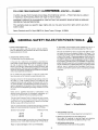
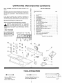
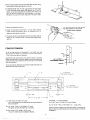
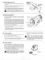
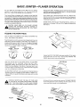
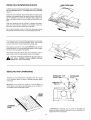
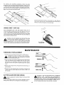
owners
manual
MODELNO.
149.236320
SERIAL
OR CODE
NUMBER:
Model and code number may be
found on the back of the base.
You should record both model and
code number and retain in a safe
place for future use.
CALIFORNIA
OWNERS: a unique
serial code number is stamped on
the underside of the machine.
CAUTION:
Read All Instructions
Carefully
Before Starting Assembly and Use.
SWAIRS / r.RRFTSMRN®
51_.INCH
JOINTER-PLANER
• assembly
• operating
Save This Manual For
Future Reference.
• repair parts
SEARS,
ROEBUCK
d_o-15A- oo
AN D CO., Dept. 698/731A,
Sears Tower,
Ch icago,
IL 60684
FULL ONE-YEAR
WARRANTY
ON
£RRFTSMRN,
JOINTER
If within one year from the date of purchase, this Craftsman Jointer
in material or workmanship, Sears will repair it, free of charge.
WARRANTY SERVICE IS AVAILABLE
CENTER IN THE UNITED STATES.
This warranty gives you specific
state to state.
BY CONTACTING
-- PLANER
-- Planer fails due to a defect
THE NEAREST SEARS STORE OR SERVICE
legal rights and you may also have other rights which vary from
Sears, Roebuck and Co. Dept. 698/731A, Sears Tower, Chicago,
IL 60684.
GENERAL SAFETY RULES FOR POWER TOOLS
1. KNOW YOUR POWER TOOL
For your own safety, read the owner's
manual carefully.
Learn its application
and limitations
as well as the specific
hazards peculiar to this tool.
2. GROUNDING
INSTRUCTIONS
A. All grounded,
cord-connected
tools:
In the event of a malfunction
or breakdown,
grounding
provides a path of least resistance for electric current to reduce
the risk of electric
shock. This tool is equipped
with an
electric cord having an equipment-grounding
conductor
and
a grounding
plug. The plug must be plugged into a matching
outlet that is properly installed and grounded in accordance
with all local codes and ordinances.
B. Grounded,
cord-connected
tools
supply circuit
having a nominal
rating less than 150 volts:
intended
for use on a
This tool is intended for use on a circuit that has an outlet
that looks like the one illustrated
in Sketch A in Figure 1. The
tool has a grounding
plug that looks like the plug illustrated
in Sketch A in Figure 1. A temporary adapter, which looks like
the adapter illustrated
in Sketches B and C, may be used to
connect this plug to a 2-pole receptacle as shown in Sketch
B if a properly grounded outlet is not available. The temporary
adapter should be used only until a properly grounded outlet
can be installed by a qualified electrician.
The green-colored
rigid ear, lug, etc. extendirig
from the adapter must be connected to a permanent
outlet box.
ground
such as a properly
grounded
Do not modify the plug provided - if it will not fit the outlet,
have the proper outlet installed by a qualified electrician.
Improper connection
of the equipment-grounding
conductor
can result in a risk of electric
shock. The conductor
with
insulation
having an outer surface that is green with or without yellow stripes is the equipment-grounding
conductor.
If
repair or replacement of the electric cord or plug is necessary,
do not connect the equipment-grounding
conductor
to a live
terminal.
Check
with
a qualified
grounding
instructions
in doubt as to whether
electrician
or
serviceman
are not completely
understood,
the tool is properly grounded.
The use of any Extension
of Grounded I (I I / I
_I ( I , ) t Cover
Meta=Screw
____Out,et
Box---_
_
Grounding
Pin
(A)
(B)
if the
Adapter
or if
g
Cord will cause some loss of power.
(G)
To keep this to a minimum
and to prevent overheating
and
motor burn-out, use the table below to determine
the MINIMUM wire size (A.W.G.) Extension
Means
Cord.
Figure I m Wiring Methods
Use only 3-wire extension cords that have 3-prong grounding
plugs, and 3-pole receptacles
that accept the tool's plug.
Extension
Cord Length
Wire Size, A.W.G.
3. KEEP GUARDS
25 Feet
50 Feet
16
16
100 Feet
14
Extension Cords suitable for use with your Jointer-Planer
are
available at your nearest Sears Catalog Order or Retail Store.
Repair
or replace
damaged
or worn
cord immediately.
in working
IN PLACE
order and in proper adjustment
4. REMOVE ADJUSTING
and alignment.
KEYS AND WRENCHES
Form habit of checking
to see that keys and adjusting
wrenches are removed from tool before turning on tool.
5. KEEP WORK AREA CLEAN
Cluttered areas and benches
invite accidents.
6.DON'T
USE
INDANGEROUS
ENVIRONMENT
Don'tusepower
toolsindamp
orwetlocations,
orexpose
themtorain.Keep
workarea
wellillumina'ced.
7.KEEP
CHILDREN
AWAY
Allvisitors
should
bekeptasafedistance
fromworkarea.
8.MAKE
WORKSHOP
KIDPROOF
withpadlocks,
master
switches,
orbyremoving
starter
keys.
9.DON'T
FORCE
TOOL
It willdothejobbetterandbesaferattherateforwhichit
wasdesigned.
10.USE
RIGHT
TOOL
Don'tforcetoolor'attachment
todoajobforwhichitwasnot
designed.
11.WEAR
PROPER
APPAREL
Nolooseclothing,gloves,neckties,
rings,bracelets,
or
jewelry
togetcaught
in moving
parts.Nonslip
footwear
is
recommended.
Wear
protective
haircovering
tocontain
long
hair.
12.ALWAYS
USESAFETY
GLASSES
Alsousefaceor dustmaskif cuttingoperation
is dusty.
Everyday
eyeglasses
onlyhave
impact
resistant
lenses.
They
areNOT
safety
glasses.
13.SECURE
WORK
Useclamps
oravisetoholdworkwhenpractical.
It'ssafer
thanusingyourhandandfreesbothhands
tooperate
tool.
14.DON'T
OVERREACH
Keep
yourproper
footing
andbalance
atalltimes.
15.MAINTAIN
TOOLS
INTOPCONDITION
Keep
toolssharp
andcleanforbestandsafest
performance.
Follow
instructions
forlubricating
andchanging
accessories.
16.DISCONNECT
TOOLS
FROM
POWER
SOURCE
beforeservicing
andwhenchanging
accessories
suchas
blades,
bits.cutters,or whenmounting
andre-mounting
motor.
17.AVOID
ACCIDENTAL
STARTING
Makesureswitchis in"OFF"position
before
plugging
in
cord.
18.USE
RECOMMENDED
ACCESSORIES
Consult
theowner's
manual
forrecommended
accessories.
Useofimproper
accessories
maybehazardous.
19.NEVER
STAND
ONTOOL
Serious
injury
couldoccurifthetoolistipped
orifthecutting
toolisunintentionally
contacted.
20.CHECK
DAMAGED
PARTS
Before
furtheruseofthetool,a guard
or otherpartthatis
damaged
should
becarefully
checked
toensure
thatit will
operate
properly
andperform
itsintended
function
- check
foralignment
of moving
parts,bindingof movingparts,
breakage
ofparts,mounting,
andanyotherconditions
that
mayaffect
itsoperation.
Aguard
orotherpartthatisdamaged
should
beproperly
repaired
orreplaced.
OFFEED
21.DIRECTION
Feedworkintoa bladeor cutteragainst
thedirection
of
rotation
oftheblade
orcutteronly.
22.NEVER
LEAVE
TOOLRUNNING
UNATTENDED.
TURN
POWER
OFF.Don'tleave
tooluntilit comes
toa complete
stop.
Theoperation
ofanypowertoolcanresultinforeignobjects
beingthrownintotheeyes,whichcanresultin severe
eye
damage.
Always
wear
safety
goggles
complying
withANSI
Z87.1
(shown
onPackage)
before
commencing
power
tooloperation.
Safety
Goggles
areavailable
atSears
retailorcatalog
stores.
TABLE OF CONTENTS
GENERAL
SAFETY RULES FOR POWER TOOLS ............
UNPACKING
AND CHECKING
CONTENTS
SAFETY RULES FOR JOINTER-PLANER
ASSEMBLY
......................
..........................................
Depth of Cut Hand Knob
Chip Deflector
Checking
..................
..................................
Blades ...................................
Fence ..................................................
Fence Extension
INSTALLING
THE JOINTER-PLANER
CONTROLS
AND
ADJUSTMENTS
Depth of Cut Hand Knob
Fence Adjustment
Cutter Guard
ON/OFF
Feeding
5
Using Holddown/Push
5
.........................
.......................
................................
........................................
.............................................
Switch ...........................................
OPERATION
the Workpiece
Beveling,
Chamfering
...................
..................................
Blocks
............................
.................................
Using a Wet/Dry Vac .....................................
10-12
10
11
11, 12
12
5
6
6, 7
..........................................
BASIC JOINTER-PLANER
4
5-7
............................................
Cutter
2, 3
7
8
8-9
MAINTENANCE
Timing
........................................
Belt Replacement
Cutter Guard Return Spring
Blade Replacement
General
Maintenance
12, 13
................................
..............................
and Adjustment
......................
....................................
12
12
13
13
8, 9
9
9
9
REPAIR
PARTS
.........................................
TROUBLE SHOOTING ......................................
How to Order Replacement
Parts .........................
14, 15
16
16
UNPACKING
Model 149.236320
carton.
Jointer-Planer
is shipped
AND CHECKING
complete
in one
TABLE OF LOOSE PARTS
LU.
Z.
I.
LL.
Separate all parts from packing materials and check each one
with the illustration
and the list of loose parts to make certain
all items are accounted
for, before discarding
any packing
material.
F-'
O.
,-n:
LU:
Cf)"
If any parts are missing,
do not attempt
to assemble
the
jointer-planer,
plug in the power cord or turn the switch on
until the missing parts are obtained and are installed correctly.
o:
uJ:
z:
Wipe
all parts thoroughly
CONTENTS
with a clean, dry cloth.
a:
Apply a coat of clear automobile
I._.
paste wax to the tables.
,_WARNING:
FOR YOUR OWN SAFETY, NEVER CONNECT TO POWER SOURCE UNTIL ALL ASSEMBLY
STEPS ARE COMPLETE,
AND YOU HAVE READ AND
UNDERSTAND
THE SAFETY AND OPERATIONAL
INSTRUCTIONS.
2::
a:
-J.
BOLT FINDER
Use to identify
fastener
size. Hold head of screw
against folded edge. Inside diameter
of sized
circle is for nut, outside
diameter is for screw.
O.
a:
O'
318' 5/16"
114" ÷10
÷8
ITEM DESCRIPTION
NO.
A
B
C
D
E
F
G
*H
*J
*K
*L
M
N
*O
*P
*Q
*R
*S
T
U
V
W
QTY.
Jointer-Planer
.....................................
Fence .............................................
Fence Bracket .....................................
Fence Segment ....................................
Tilt Indicator Assembly ..........................
Chip Deflector .....................................
Hand Knob ....................................
318" Lockwasher
...................................
1/4"-20 x 314" Hex Cap Screw .......................
1/4 Split Lockwasher
...............................
1/4 Flat Washer ....................................
Fence Lock Knobs .................................
9132"lDx1_7132"ODx118"ThickWasher
............
#10-24 x 1/2 Machine Screw ......................
#10 Flat Washer ....................................
#8-32 x 112" Flat Head Machine Screw ...............
#8-32 Hex Nut .......................................
#8 Flat Washer .....................................
Push Block ........................................
2-1/2" to 1-1/4" Vac. Hose Adapter ...................
5/32" Hex Key (Allen Wrench) .......................
Owner's Manual ...................................
* Supplied
1/2"
1
1
2
2
2
1
1
1
4
4
4
2
2
2
2
6
6
6
2
1
1
1
in loose parts bag
1/_'4
D
M
B
\
\
C
\
\
G
TOOLS REQUIRED
_.......3
14mm or 9/16" Wrench
10mm Wrench
8mm or 5/16" Wrench
Medium Slotted Screwdriver
#2 Phillips Screwdriver
Combination
Squa,-e
i L'_
SAFETY RULES FOR JOINTER--PLANER
Safety is a combination of operator common sense and alertness at all times when the Jointer--Planer
used. Study these rules and general safety rules before operating and retain them for future use.
1. WEAR EYE PROTECTION.
9.
2. NEVER MAKE JOINTING
1/8 INCH -- PER PASS.
OR PLANING
CUT DEEPER THAN
ALWAYS
narrower
inches.
- Use hold down/push
blocks for jointing material
than 3 inches, or planing material thinner than 3
10. ALWAYS3. FEED WORKPIECE
4. KEEP FINGERS
fixtures
AGAINST
AWAY
ROTATION
FROM
OF CUTTER.
REVOLVING
CUTTER
-- use
when necessary.
OPERATION
6. NEVER FORCE CUTTING ACTION. Stalling or partial stalling
of motor can cause major damage. Allow motor to reach full
speed before cutting.
7. NEVER
- Attempt
to
perform
an abnormal
or
operation
without study and the use of adequate
/push blocks, jigs, fixtures, stops, etc.
8. NEVER - Attempt
Keep cutter sharp.
11. NEVER- Use in an explosive
motor may ignite fumes.
12. OUTDOOR
5. NEVER PERFORM
JOINTING
OR PLANING
WITH CUTTER HEAD GUARD REMOVED.
little
used
hold down
EXTENSION
atmosphere.
CORD
Normal sparking
USE - When
tool
of
is used
outdoors, use only extension cords suitable for use outdoors.
Outdoor approved cords are marked with the sL'ffix W-A, for
example- SJTW-A or SJOW-A.
13. ALWAYS
use identical
14. This tool is intended
WARNING:
FREQUENT
replacement
parts when servicing.
for RESIDENTIAL
USE ONLY.
DO NOT ALLOW FAMILIARITY
(GAINED
FROM
USE OF YOUR JOINTER--PLANER)
TO BECOME
COMMONPLACE.
ALWAYS REMEMBER
FRACTION OF A SECOND IS SUFFICIENT
INJURY.
to cut small pieces.
is being
THAT A CARELESS
TO INFLICT SEVERE
WARNING: DO NOT AT ANY TIME LET BRAKE FLUIDS, GASOLINE, PENETRATING OILS, ETC.
COME IN CONTACT WITH PLASTIC PARTS. THEY CONTAIN CHEMICALS THAT CAN DAMAGE
AND/OR DESTROY PLASTICS.
,_
ASSEMBLY
DEPTH
OF CUT HAND
1. Find one 3/8 lockwasher
the parts bag.
KNOB
and the depth of cut hand knob from
3/8
2. Turn the nut on the height adjustment
threads extend beyond the nut.
3. Place Iockwasher
on height
hand knob onto screw.
screw
adjustment
until
screw
4. Back nut up against hub of hand knob. Tighten
9/16 wrench while holding hand knob.
five full
and thread
with 14ram or
t
DEPTH
HAND
LOOSEN
OF CUT
KNOB
AND
RETIGHTEN
CHIP DEFLECTOR
1. Loosen
the
screw
T H I S SC R E W _..........._.
in the
center
of vacuum
port
of
chip
the chip discharge
and
discharge.
2. Install
slot of chip deflector
the flat washer
,_CAUTION:
between
and retighten.
THE CHIP
DEFLECTOR
MUST
BE IN PLACE
FOR SAFE OPERATION. FAILURE TO INSTALL THE CHIP
DEFLECTOR MAY RESULT IN PERSONAL INJURY.
DEFLECTOR
HEX
NUT
CHECKING
,_
CUTTER
BLADES
BLADE
POSITION AND CORD IS UNPLUGGED
BEFORE PROCAUTION:
MAKE SURE THE SWITCH IS IN THE OFF
CEEDING WITH CHECKING CUTTER BLADES.
I
CLAMP---.
m .
CUTTER..,,._i
HEAD
The blades in your Joint÷r-Planer
have been adjusted
at the
factory to assure proper operation. Shipping and handling, however, may cause misalignment.
For accurate cutting, the blades
must be .003-in. higher than the outfeed table (thickness
of a
piece of paper) when positioned
at the highest point.
CLAMP
SCREW _
1. Block the cutter guard open with ascrap piece of wood about
5-1/2" long between the fence and cutter guard.
CHIP
2. Locate the slot in the cutter head shaft through the small
hole in the backside of the machine directly above the vacuum
port.
Rotate the cutter head with a screwdriver
until one of
the blades is at its highest position.
3. Place a straight
edge over the outfeed
BACK SIDE
MACHINE
DISCHARGE/VACUUM
OF
table and the blade,
The straight edge must touch evenly on the outfeed table at
both ends of the blade. Rotate the cutterhead
slowly, and
making sure the blade lightly touches the straight edge. If the
straight edge rises or blades do not touch, follow the "REPLACING CUTTER BLADES" procedure in the "MAINTEN.
ANCE" section.
STRAIGHT-
EDGE
,
iltlI
_OUTFEED
TABLE
FENCE
1. From
among
the loose
parts
find
the following:
LOCK
NOTE:
USE OF WASHERS
LESS
THAN
1/8 THICK
MAY
RESULT
IN FENCE
TIGHTENING
PROBLEMS
(1) Fence
(2) Fence Brackets
(2) Fence Segments
(2) Tilt Indicators
(2) Lock Knobs
(4) 1/4-20 x 3/4" Hex Cap Screws
(4) 1/4 Lock Washers
(4) 9/32 ID x 9/16 OD x 1/16 Thick Washers
(2) 9/32 I D x 17/32 OD x 1/8 Thick Washers
(6) #8-32 x 1/2 Flat Head Machine Screws
(6) #8 Flat Washers
(6)#8.32 Hex Nuts
(2) #10-24 x 1/2 Pan Head Machine Screws
(2) #10 Flat Washers
on machine
with
fence
brackets
lock knobs with 9/32 ID x 17/32 OD x 1/8 thick washers
thru slots in fence segments
SEGMENT
÷B
HEAD
inside the fence segments,
4. Position
\,
÷8-32
2. Attach fence segments
to fence with #8-32 flat head screws,
#8 flat washers and #8-32 hex nuts.
fence
fT/32OO
W
FENCE
snug but do not tighten.
assembled
9/32
I0 X
X 1/8 THK
FENCE
1. Attach fence brackets
to base using 1/4-20 x 3/4 hex cap
screws, 9/32 IO x 1116 thick washers and 1/4 lock washers,
3. Place
--
KNOB
_.
and thread into fence brackets.
'!'8-32
X 112 FLAT
MACHINE
SCREW
HEX
NUT
FLAT
WASHER
5. Place square against face of fence and table surface.
fence square to table and tighten lock knobs.
6. THERE MUST BE 1/32" TO 1/16" gap between
Bring
the lower edge
of the fence and jointer tables (with table set for 0" cut). To
adjust, move fence assembly by loosening the 1/4-20 x 314
hex cap screws attaching
the fence brackets
to the base.
Retighten hex cap screws after adjustment
has been made.
7. Recheck
8. Install
screw
squareness
of fence.
TILT
INDICATOR
SHOULD
BE LINED
UP WITH
FENCE
SEGMENT
AT THE O'MARK.
tilt indicators
with #10-24 x 1/2 pan head machine
and #10 flat washers. Set 0 ° of indicators
to 0 ° of
segments,
and tighten
9. The fence should
FENCE
and will accurately
and 45 ° outboard
OVER
TIGHTEN
measure
(see adjustments
EXTENSION
screws
q
_C
To aid in edge jointing
of workpieces
extend the fence height. The extension
1" (3/4" thick) stock pine or hardwood.
Use #8 flat head wood
NOT
the screw.
now be adjusted
angles to 45 ° inboard
section).
DO
BI
4" and wider, you may
can be constructed
of
of sufficient
length
1/4_
A
to securely
attach the extension to the fence. Make sure that the head of the
screws are below the surface of the fence so as not to interfere
4,8 FLATHEAD _
COUNTERSUNK SCREWS
with the workpiece.
For extra stability, additional
countersunk
vided near the ends of the fence.
i
_-'j'rll___
._I____
114
FENCEJ
holes have been pro-
,-E OPTIONAL
,/ FOR EXTRA STABILITY
-<_-
FOR EXTRA STABILITY
L
_____
---
_
-,,--
O OPTIONAL
1/2
A
A= 11/16 Thick x 2" Wide x 10" Long
The 11/16 thickness can be obtained
the jointer-planer.
OPTIONAL
by planing
the board on
-- For Extra Stability
D= 11/16" Thick
x 2" Wide x 2" Long, 2 Pieces
E= 1/2" to 314" Thick
B= 112" to 314" Thick x 3-1/2" Wide x 10" Long
This piece may also be made out of plywood.
C= 314" Thick x 2-1/2" Wide x 19-1/2" Long
The 2-112" width may be increased if desired.
x 3-1/2" Wide
x 2" + Long, 2 Pcs.
NOTE: Cut both D pieces from the same stock or thickness
as
board A and cut both E pieces from the same stock or thickness
as board B.
INSTALLING
THE JOINTER--PLANER
3/8 OlA
If the Jointer-Planer
is to be used in a permanent
location,
it
should be fastened securely to a firm supporting
surface such
as a workbench.
Holes should be drilled through supporting
surface of the workbench as illustrated.
Each foot of the JointerPlaner should be bolted securely using 5/16" diameter machine
bolts, 5/16" hex nuts, and lock washers.
Bolts should be of
sufficient length to accommodate
foot of Jointer-Planer,
washer,
hex nuts, and thickness
of supporting
surface. Tighten all four
bolts securely. If the Jointer-Planer
is to be used in a portable
application,
it is recommended
that it be fastened to a mounting
board. The board should be of sufficient
size to avoid tipping of
Jointer-Planer
while in use. Any good grade of plywood or chipboard with a 3/4" minimum
thickness
is recommended.
Mount
Jointer-Planer
board securely
to board using hole pattern as shown.
to workbench
or supporting surface.
Clamp
4, HOLES
t
I
i
i
I
--4
1
,q-
I
I
+--.
i
i
I
I
3-1/2-I
i
Supporting
surface where Jointer-Planer
is mounted should be
examined carefully after mounting to insure that no movement
during use can result. If any "tipping"
or "walking"
is noted,
secure workbench or supporting
surface before operating.
CONTROLS
[
24
_
AND ADJUSTMENTS
CAUTION: MAKE SURE THE SWITCH IS OFF AND THE CORD IS UNPLUGGED
FORMING ANY CHECKS OR ADJUSTMENTS.
2
BEFORE PER-
FENCE
\
3
CUTTERGUARD
/
4
1. DEPTH
OF CUT HAND
_
/
ON-OFF
1
the
table
KNOB
TABLE
is lowered
for the
maximum
OF
CUT HAND
KNOB
1/8"
depth cut, the hand knob will be relieved of tension and
will be loose. If this is disturbing,
simply turn the hand knob
clockwise
until it is again under tension. Turn the knob no
more than 1/2 turn after it is again under tension. This will
not change
exceeded.
the depth
of
cut
OF CUT
KNOBS
SWITCH
Turning the hand knob clockwise raises the infeed table and
decreases
the depth of cut. Turning it counter-clockwise
lowers the infeed table and increases the depth of cut to the
maximum !/8" depth per pass.
NOTE: When
DEPTH
HAND
setting
unless
1/2 turn
is
8
TO CHECK
DEPTH
OF CUT
OUTFEED
TABLE
a. Place a straight
feed table.
b. Measure
straight
from
edge on the outfeed
table extending
over the inMAX. DEPTH
,OF CUT 1/8"
the surface
of the infeed table to the bottom
of the
edge. This will be the depth of cut.
NOTE:-This
Jointer-Planer
will make a maximum
1/8" deep cut. To
reduce the DANGER of kickback and possible injury, the depth of cut
should not exceed 1/16" when cutting wood wider than 1-112".
,_
CAUTION:
MAKE SURE THE SWITCH IS OFF AND THE
CORD tS UNPLUGGED BEFORE PERFORMING THIS CHECK.
2. FENCE
ADJUSTMENT
The fence can be adjusted to cut angles from 0 ° to 45 °. Stop pins
allow automatic
setting to 0 °, 221/2 °, 30 ° or 45 ° in either the inboard
or outboard direction.
TO ADJUST: Loosen fence lock knobs and lift the stop pins out and
turn to lock out. Move the fence to the desired angle. If it is one of the
commonly
used angles listed above, release the stop pins and they
will pop into place when the correct angle is reached. Tighten the
fence lock knobs to lock the fence in place. For a less common angle
or to fine tune to an angle less than the 5 ° divisions on the fence segment. Pul! and lock out the stop pins and use theo ° to 5 ° scale on the
tilt indicator to set the exact angle desired.
1. FOR OUTBOARD TILT add the reading
reading on the fence segment.
on the tilt
2. FOR INBOARD TILT subtract
the tilt indicator
reading on the fence segment. Always tighten
maintain the desired setting.
3. CUTTER
indicator
to the
The cutter guard provides protection
over the cutter
always be in place and functioning
properly.
head. It must
TILT
INDICATOR
FENCE
b. Open the cutter guard all the way until it stops and release
it several times. It should always return to its original
position.
CAUTION:
PROPERLY,
properly.
a. Pass a !14" thick piece of wood over the cutter head between
guard and fence. The guard must return automatically.
4, ON-OFF
P
reading from the
the lock knobs to
GUARD
Check the guard to make sure it is functioning
STOP
the
IF THE CUTTER GUARD FAILS TO OPERATE
THE
CUTTER
GUARD
RETURN
SWITCH
The operating
positions
of the "On-Off"
switch are located on the
front of your Jointer-Planer.
Push the switch up to turn your JointerPlaner "on" and down to turn your Jointer-Planer
"off". The switch
has a switch key which, when removed, allows the switch to be locked in the "off" position. To activate the locking feature push switch
to "off" position and pull switch key.
To turn Jointer-Planer
"on" after it has been locked in the "off" position, the switch key must be replaced in the switch.
,_WARNING:
BE SURE SWITCH IS IN THE "OFF"
POSITION
BEFORE PLUGGING JOINTER.PLANER INTO POWER SOURCE
FAILURE TO DO SO COULD
RESULT IN ACCIDENTAL
STARTING CAUSING SERIOUS INJURY.
SWITCH
\ SWITCH KEY
9
SPRING
WILL NEED REPLACING.
CONTACT YOUR NEAREST
SEARS STORE OR SERVICE CENTER FOR REPLACEMENT SPRING AND INSTRUCTIONS
BEFORE USING
THE JOINTER--PLANER.
BASIC JOINTER---PLANER
OPERATION
For your safety do not exceed a 1/16" deep cut on a planing
operation for work pieces wider than 1-1/2". For work pieces less
than 1.112", a 118" cut can be taken at a slow feed rate.
For your own safety, ALWAYS use hold down/push blocks when
JOINTING wood that is NARROWER than 3 in. or when PLANING
WOOD THAT IS THINNER than 3 in.
This Jointer-Planer
is designed with a special cutter head and
internal baffle that 'blows the sawdust and chips from the rear of
the machirie. To keep this system operating
properly, the motor
speed should be maintained.
A feed rate that is too fast will slow
Do not plane, joint or bevel wood shorter
the motor down resulting in a poor cut and poor chip discharge.
The type of wood, wood grain, and moisture content of the wood
all affect an acceptable feed rate.
CAUTION:
MAKE
SURE
ALL
SIX
BLADE
,_SCREWS
ARE TIGHTENED
SECURELY
TEMPTING TO TURN THE MACHINE "ON"
ING ANY OPERATION.
FEEDING
this
For best results, take light cuts. For average planing, jointing, or
beveling, a cut between 1/32 and 1/16 in. deep will produce the
best results.
LOCKING
BEFORE ATOR ATTEMPT-
THE WORK PIECE
Hold the board
fence..,
than 12 in. Material
short is more difficult to control while being cut. Small pieces of
wood can tip over on the tables or into the cutterhead and can be
kicked back toward you.
firmly
DOWN on both
tables
and AGAINST
the
keep fingers close together.
Feed the board at a continuous
even rate of speed until the cut is
\
made along the entire length of the board. Any hesitation
or
stopping could cause a "step" to be cut on the edge of the board
which would cause the board to ride up on the outfeed
table
resulting
in a "crooked"
edge on the board.
WTTH THE QRAJN
WORK
PIEQE
_A_
_
AGAIN6T
F'IE]BD
WORK
PIECE
_
GRAIN
<llu=m=
FEED
Always feed WITH THE GRAIN whenever possible. If the nature
of the work piece is such that it must be fed AGAINST THE
GRAIN, take very light cuts and feed slowly.
RCrrAI"K_
HAND-OVEI-HAHD
Start with the left hand in the forward position.
As the RIGHT
hand passes over the cutterhead,
remove the LEFT hand...
CONTINUE feeding
while placing
the LEFT hand behind the
RIGHT. Continue feeding in this manner "hand over hand," until
the entire length of the board is cut. Pressure should be applied
over the cutterhead and outfeed table.
DO NOT FEED TOO FAST. A slow steady rate of feed produces a
smooth accurate cut. Feeding too fast causes a "rippled"
cut...
makes it difficult to guide the workpiece accurately and could be
hazardous.
At the end of the cut, position your hand on TOP NEAR THE END
of the work piece and continue feeding the work piece until the
cutter guard has returned to its closed position.
,_WARNING:
PLACE
HEELWHEN
OF YOUR
HAND
AT THE ENDNEVER
OF THE
WORKTHE
PIECE
FINISHING
A CUT. THIS COULD RESULT IN YOUR HAND COMING
IN CONTACT WITH THE CUTTER CAUSING SERIOUS INJURY.
WRONG
),-
10
USING
HOLD DOWN/PUSH
BLOCKS
HAND-OVER HAND
ALWAYS use the hold down/push blocks when JOINTING wood
that is NARROWER than 3 in. or PLANING wood that is THINNER
than 3 in.
/
/
Grasp the hold down/push
blocks firmly with the fingers close
together and wrapped around the handle. Position them flat on
top of workpiece,
and push the workpiece
down against the
table to provide a quality cut and minimize the chance of a kickback.
Hold down pressure must be sufficient
to prevent
push block from sliding or slipping on the surface
piece when advancing work piece over cutter head.
hold down/
of the work
Use a hand-over-hand
motion
of the hold down/push
blocks
being careful to maintain control of the workpiece at all times.
This means that once the work piece has passed the cutter head
onto outfeed
table, one hold down/push
block must always
maintain contact with the work piece with outfeed table.
When planing wood 3/4 in. thick and NARROWER than the hold
down/push
block, tilt the hold down/push block so that it clears
the top of the cutter guard while feeding.
Never plane wood that is thinner than 1/2 in.,.because
it is apt to
split or shatter and thus has a greater tendency to kickback.
IF THE HOLD
SLIP WHILE
_CAUTION:
IMMEDIATELY
BEVELING
FEEDING, DOWN/PUSH
CLEAN
RUBBER
BLOCKS SURFACE
TEND TO
WITH SANDPAPER.
AND CHAMFERING
OUTBOARD
The fence on your jointer-planer is adjustable
to 45 ° outboard.
Adjust the fence to desired
lock knobs.
BEVELING
is the cutting
from 45 ° inboard
angle and tighten
of. an angle on the entire
TILT-_
edge of a
board, Beveling may require several passes due to the depth
cut needed to bevel entire edge of board.
of
BEVEL
EDGE
CHAMFER
EDGE
CHAMFERING
is removing only the corner of the edge of a
board. Normally a chamfer is made with one cut; therefore, a cut
deeper than 1/16" may be made.
11
I
For beveling
and chamfering
operations,
follow
the same
procedure as for jointing
and planing described on pages 10 and
11. Before performing
these operations make sure the surface of
the work piece that contacts the fence is flat and smooth. Maintain firm control of the work piece at all times holding
against fence surface and table surfaces.
it firmly
Use hold down/push
blocks
for wood
under 3 in. wide. Position
them so you have control of the work piece at all times
they do not contact the guard or the cuiter head.
USING
A WET--DRY
and so
VAC
Your Jointer-Planer
has a rear chip exhaust
which fits all
Craftsman
Wet-Dry Vacs with a 2-1/2 inch hose. A 2-1/2 in. to
1-1/4 in. hose adapter is supplied with the machine for 1-1/4 in.
hose connections.
Attaching
a Craftsman Wet-Dry Vac will keep
your work area cleaner. Craftsman Wet-Dry Vacs are available at
Sears Catalog and Retail Stores.
,_WARNING:
DO NOT REMOVE CHIP DEFLECTOR EVEN
IF VACUUM HOSE REMAINS PERMANENTLY
ATTACHED TO MACHINE.
NEVER LEAVE HOSE ON MACHINE
DURING OPERATION
IF A VAC IS NOT USED DURING OPERATION OR THE HOSE AND MACHINE WILL CLOG WITH CHIPS.
CHIP EXHAUSTVACUUM PORT
MAINTENANCE
TIMING
1. Unplug
BELT REPLACEMENT
your Jointer-Planer
and put switch
in OFF position.
PLANER
RESULT
IN ACCIDENTAL
STARTING
DANGER: COULD
FAILURE
TO UNPLUG
YOUR JOtNTER-CAUSING SERIOUS INJURY.
,_
2. Remove access cover plate by loosening two pan head
under the machine and one located under the cutter
being careful not to damage or disconnect
the switch
DO NOT remove cutter guard or guard spring from
cover.
3. Remove old timing
ward pressure.
belt by turning
screws
guard,
wiring.
access
belt and maintaining
REMOVE
_'_
out-
4. Replace with new timing belt by turning belt and maintaining
inward pressure. NOTE: Make sure full width of belt is on
both pulleys.
CUTTER
,_DO
Oil and
GUARD
RETURN
NOT LUBRICATE
'GUARD.
lubricating
products
damage and/or destroy
SPRING
,_
may contain
chemicals
that
IF THE CUTTER GUARD
FAILS TO OPERATE
PROPERLY
(SEE "CONTROLS
AND ADJUSTMENTS"
SECTION), THE CUTTER GUARD RETURN SPRING WILL
NEED REPLACING. CONTACT YOUR NEAREST SEARS STORE
OR SERVICE CENTER FOR REPLACEMENT
SPRING AND IN-
THE PIVOT POINT OF THE CUTTER
the cutter guard or other plastic
CAUTION:
can
parts.
STRUCTIONS
12
BEFORE USING THE JOINTER--PLANER.
BLADE REPLACEMENT
AND ADJUSTMENT
NOTE: To rotate the cutterhead
or to hold it steady, use a
screwdriver
in the slot in the cutter shaft through the small hole
in the rear of the machine just above the vacuum port.
BLADE
1. Unplug your Jointer-Planer
and put switch in off position.
DANGER: Failure to unplug your Jointer-Planer
could result
in accidental starting causing serious injury.
2. Block the cutter
WOOD
BLOCK
CUTTER
HEAD
CLAMP
.ADE
guard open.
CUTTER
3. Using the 5/32" hex key (Allen wrench), remove the three (3)
blade lock screws securing blade and blade clamp.
4. Lift blade and blade clamp
5. Clean any sawdust
removed.
from
6. Place blade clamp
against
from cutter
cutterhead
head.
and any parts
the replacement
you have
BLADE
blade and replace
in cutterhead with the (3) blade lock screws. NOTE: Retighten
blade lock screws so that the blade is held by friction butstill
allows for blade movement.
CUTTER HEA_
BLADE _i_BLADE
7. Place a straight edge across
cutterhead opening.
the out feed table and across
CLAMP
the
LOCK SCREW
8. Rotate the cutterhead
until the blade contacts
the straight
edge (rotate backwards
to prevent damage to the cutting
edge). A properly adjusted
blade will lightly tick (touch) the
straight edge.
NOTE: Check blade height at both ends of blade. After
one is adjusted, repeat for second blade.
9. BLADE TOO HIGH: If the straight edge is lifted by the blade,
it must be lowered. Tap the blade lightly with a scrap piece of
wood to lower it.
CHIP
the first
DISCHARGE/VACUUM
/
BACK 81DE OF
MACHINE
10. BLADE TOO LOW: If the blade does not touch the straight
edge, it should be raised. Pry the lower edge of the blade with
a screwdriver
against the edge of the outfeed table. Always
protect the edge of the table with a scrap of wood or piece of
cardboard.
|
8TRA I GHTEDGE -_
11. Tighten blade lock screws.
12. Recheck blade adjustment,
with outfeed table.
13. Recheck
,_
screws
making
sure blade
is still
level
to be sure they are secure.
OUTFEED
TABLE
DANGER: COULD
FAILURERESULT
TO IN
TIGHTEN
SCREWS
SERIOUS BLADE
INJURY. LOCK
GENERAL
MAINTENANCE
Keep your Jointer-Planer
clean and adjusted
properly
for
maximum
performance
and longevity of the machine.
Do not
allow pitch to accumulate
on the tables, fence, cutter guard, or
blades. Clean them frequently
with Sears Gum and Pitch
Remover stock number 49191.
DO NOT allow anything to obstruct the chip discharge
disturb the air flow produced by the cutter head.
,_WARNING:
DO NOT AT ANY TIME LET BRAKE FLUIDS,
GASOLINE,
PENETRATING
OILS, ETC. COME IN CONTACT WITH PLASTIC PARTS. THEY CONTAIN
CHEMICALS THAT CAN DAMAGE AND/OR DESTROY PLASTICS.
starting. Dislodge the chips and debris with a pencil or small
wood dowel. When resuming operation with the same work piece,
feed at a slower rate to avoid re-clogging.
Use of a Wet-Dry Vac
will virtually eliminate the chances of clogging.
outlet
or
If the chip discharge
of your Jointer-Planer
clogs with chips,
turn the switch OFF and UNPLUG the unit to avoid accidental
13
REPAIR PARTS
u_
8
uJ
I-Z
O
"T"
O
Z
OO
Z
_O
I-LL
<1:
nO
o
/
o
¢N
14
o
E
,,-I,
oz
8
o
po;
5 ,¸
2
,,=, R
6
a..
o
"10
Z
00
,.6
Z
,<
O3
ILL
,<
×__
_,
rr
0
z
o
I,Q.
_=_
_
-_
X-r_
E-_
ab
X
15
TROUBLE SHOOTING
TROUBLE
CHART
PROBABLE
CAUSE
Woodstrikes outfeed
table after passing over
cutterhead
Ripples on planed surface.
Planedsurface not straight.
REMEDY
1. Bladesimproperly adjusted below
surface of outfeedtable.
1. Re-adjustblades.
2. Infeed table out of adjustment
2. Contact your nearest Sears store
or service center.
1. Oneblade set higher than other.
1. Re-adjust blades
2. Dull blades.
2. Re-sharpen or replace.
3. Boardnot held firmly against fence or
outfeed table
3: Hold board firmly against fence and
outfeed table.
1. Infeed table looseor out of adjustment.
1. Adjust infeed table, see Maintenance
section.
,2. Bladesset too low.
2. Re-adjust blades.
Excessivegouging at end of cut. 1. Bladesset too high above outfeed table.
1. Reset blades.
90 ° and 45" cuts inaccurate
1. Fenceand tilt indicators not adjusted
properly.
1. Re-adjust fence, see Assembly
section.
Cutter guard does not
function properly.
1. Return spring broken, or spring
has been weakened.
1. Replace spring immediately. Contact
your nearest Sears store or service
center.
Chip discharge clogs
1. Obstruction reducing air flow.
1. Remove obstruction.
2. Cutter head speedtoo slow.
2. Decrease feed speed.
3. Woodhas high moisture content.
3. Decrease feed speed.
1. Work feed speedtoo fast.
1. Decrease feed speed.
2. Attempting to remove too much material
2. Decrease depth of cut, make
two or more cuts.
Cutter slows down
during operation
S_FARS / CRRFT$MRN
owners
manual
51/8-INCH JOINTER-PLANER
Now that you have purchased your Jointer-Planer,
should a need ever exist for
repair parts or service, simply contact any Sears Service Center and most Sears,
Roebuck and Co. stores. Be sure to provide all pertinent facts when you call or
visit.
Service
MODELNO.
149.236320
WHEN ORDERING REPAIR PARTS, ALWAYS GIVE THE FOLLOWING INFORMATION:
• PART NUMBER
• PART
• MODEL NUMBER:
149.236320
• NAME OF ITEM: 5-118 INCH
JOINTER--PLANER
DESCRIPTION
All parts listed may be ordered from any Sears Service Center and most Sears stores.
How To Order
Repair Parts
SEARS,
ROEBUCK
If the parts you need are not stocked locally, your order will be electronically
transmitted
to a Sears Repair Parts Distribution
Center for handling.
AND CO., Dept. 698/731A,
Sears Tower,
Chicago,
IL 60684
Printed
in U.S.A.