1
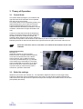
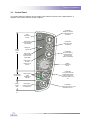
44Ultra
Laminator
Service Manual
SM110EN, Rev. 2.0
May 2003
Front Matter
SEAL 44 Ultra
Technical Service Manual
REV 1.1
Revision History
Amendments will be listed on this page, including their descriptions and dates.
REV
1.0
1.1
2.0
Date
Jan 2001
Mar 2001
May 2003
Description
Original version (pre-release).
Changes in Sparepart list and Chapter 8 (Diagrams)
Seal branding
Service Manual 44Ultra
110SM-2.0
ii
Front Matter
©2003,2000 SEAL® Graphics Europe BV
All technical and technological information included in this manual as well as any drawings and
technical specifications we have made available remain our property. They shall not be used (other
than for operation of this product), copied, reproduced, transmitted to or disclosed to third parties
without our prior written consent.
The Information contained herein is general and does not constitute any warranties or guarantees.
SEAL GRAPHICS EUROPE B.V.
Kanaaldijk O.Z. 3
P.O. Box 29
8100AA Raalte
The Netherlands
Tel: +31 572 345500
Fax: +31 572 345501
Internet:
www.SEALBrands.com
Seal Brands . . . the finishing touch
iii
Front Matter
Safety Statements
The SEAL 44 Ultra laminator has been designed with operator safety as a primary objective; however,
operators must be familiar with the controls, as well as the operation before using the unit.
The electrical and drive-system components are isolated from contact with the operator by enclosing
them within plastic end covers that are bolted on. Only qualified service technicians should remove
these protective covers after power to the machine is removed including disconnecting the power
cord.
Only qualified service technicians should remove covers for service purposes
Safety Features
The heating system is provided with an over-temperature device, which will shut off the top rollerheating element once a heating system failure occurs.
The rotation of the rollers will be switched off automatically when the light beam of the self-checking
photoelectric guard is interrupted. For example, if a panel is too thick relative to the roller nip setting,
or if a person’s hands or fingers approach the roller nip.
Once the roller rotation has been stopped and the photoelectric guard has been cleared, a deliberate
start signal has to be given in order to start the roller rotation again.
The machine has two emergency stop buttons that may be pressed in dangerous situations. The
rotation of the rollers will be stopped immediately. After releasing these buttons, a deliberate start
signal has to be given in order to start the roller rotation again.
General Hazards
Danger of getting injured by hot parts
Be careful with parts marked with this symbol, to avoid burns. The heated top roller may
have a surface temperature of 135°C (275°F).
Do not touch the roller. Even after the machine has been switched off, the roller remains
hot for a long time.
Danger of getting injured by rotating parts
Everyone working around the laminator must avoid wearing loose fitting clothing (ties!) or
dangling jewelry, which could catch in the laminator rollers.
Failure to use caution near exposed rollers could result in physical injury.
Location of the
safety labels
iv
Front Matter
Note:
When performing procedures that require the side covers to be opened, ensure
that the power cable is disconnected from the mains. Several parts, like the fast-on
connector strips of the overtemperature switch (white arrows in picture shown
below), could cause electrical shock if the power is not disconnected!
v
Front Matter
Table of Contents
1
2
3
4
Machine Characteristics ................................................................................................................... 7
1-1
Machine Description .................................................................................................................. 7
1-2
Identification .............................................................................................................................. 7
1-3
Features .................................................................................................................................... 8
1-4
Specifications ............................................................................................................................ 9
Transport & Installation................................................................................................................... 11
2-1
Transport ................................................................................................................................. 11
2-2
Workspace Requirements ....................................................................................................... 11
2-3
Setup & Installation ................................................................................................................. 11
2-4
Electrical Requirements .......................................................................................................... 11
Theory of Operation........................................................................................................................ 13
3-1
Control Knob............................................................................................................................ 13
3-2
Roller Nip settings ................................................................................................................... 13
3-3
Control Panel........................................................................................................................... 14
3-4
Motor Control........................................................................................................................... 15
3-5
Unwind Brakes ........................................................................................................................ 16
Disassembly/Reassembly Procedures ........................................................................................... 17
4-1
Plastic Covers.......................................................................................................................... 17
4-2
Heating Element ...................................................................................................................... 18
4-3
Rear Panel............................................................................................................................... 20
4-4
Control System Board & Software........................................................................................... 21
4-4-1 Control System Board.......................................................................................................... 21
4-4-2 Software............................................................................................................................... 21
5
4-5
Solid State Relay ..................................................................................................................... 22
4-6
Photoelectric Cells................................................................................................................... 23
Adjustment Procedures .................................................................................................................. 25
5-1
Laminating Pressure ............................................................................................................... 25
5-1-1 Adjustment using Load Cells and Display Unit................................................................... 25
5-1-2 Adjustment using Heat Sensitive Film ................................................................................ 27
6
5-2
Roller Nip................................................................................................................................. 29
5-3
Temperature ............................................................................................................................ 30
5-4
Photoelectric Cells................................................................................................................... 31
5-5
Drive Chain.............................................................................................................................. 32
5-6
Clutch ...................................................................................................................................... 32
5-7
Image Guide ............................................................................................................................ 33
Maintenance ................................................................................................................................... 35
vi
Front Matter
7
Troubleshooting .............................................................................................................................. 37
8
Diagrams ........................................................................................................................................ 43
8-1
Installation Diagram................................................................................................................. 43
8-2
Control Panel Diagram ............................................................................................................ 44
8-3
Safety Control System Diagram .............................................................................................. 45
8-4
Certified Electrical Components List & Sparepart Codes ....................................................... 46
8-5
Mechanical Spare Parts List, Assembly Drawings & Exploded Views.................................... 47
8-5-1 Mechanical Spare Parts List ................................................................................................ 47
8-5-2 Assembly Drawings & Exploded Views ............................................................................... 48
vii
Machine Characteristics
1 Machine Characteristics
1-1 Machine Description
The SEAL 44 Ultra laminator is an electro-mechanical device basically containing two siliconized
laminating rollers, two siliconized pull rollers and a top and bottom film unwind. Only the top roller is
heated. There are three temperature ranges; the speed can be set to any value between zero and
maximum speed. There is a set of nip values to accommodate for the various panel thicknesses.
The machine runs on a single-phase power supply.
The machine is able to perform the following processes:
• cold/hot mounting
• cold/hot laminating
• mounting & laminating in one pass
• decaling
• encapsulating
Process results can be controlled by:
• the temperature setting
• the speed setting
• the unwind tension of the film(s)
The SEAL 44 Ultra meets the Machinery Directive (89/392/EEC & applicable amendments). The
Notified Body’s TRF report (based on EN60950) is available.
rd
It is ETL and cETL listed per directive UL 1950 3 Edition 1995 and CAN/CSA C22.2 No. 950-95.
1-2 Identification
The machine identification label is located on the rear side of the machine.
The machine is available in two different voltages: 110VAC 50/60Hz and 230VAC 50/60Hz, see the
labels below.
MODEL:
POWER SUPPLY:
CURRENT:
• EQUIPMENT TO BE CONNECTED TO EARTHED MAINS OUTLET
ONLY.
• TO PREVENT ELECTRIC SHOCK, DO NOT REMOVE COVER.
• NO OPERATOR SERVICEABLE PARTS INSIDE.
• REFER SERVICING TO QUALIFIED SERVICE PERSONNEL.
SEAL 44 ULTRA
230VAC 50/60Hz
9A
SERIAL NO:
• CONECTAR EL PRODUCTO A RED DE ALIMENTACION CON TOMA DE TIERRA.
• PARE EVITAR UNA DESCARGA ELECTRICA, NO QUITE LA CUBIERTA.
• NO HAY PIEZAS REPARABLES POR EL USUARIO EN EL INTERIOR.
• REPARACIONES: CONTACTAR CON PERSONAL DE SERVICIO AUTORIZADO.
MANUFACTURED:
EN 60950
EN 50081-1
EN 50082-1
FCC Part 15 (Class B)
THIS DEVICE COMPLIES WITH PART 15 OF THE FCC RULES. OPERATION IS
SUBJECT TO THE FOLLOWING TWO CONDITIONS: (1) THIS DEVICE MAY NOT
CAUSE HARMFUL INTERFERENCE, AND (2) THIS DEVICE MUST ACCEPT ANY
INTERFERENCE RECEIVED, INCLUDING INTERFERENCE THAT MAY CAUSE
UNDESIRED OPERATION.
Hunt Graphics Europe BV
Kanaaldijk O.Z. 3, P.O.B. 29
8100AA Raalte, The Netherlands
MODEL:
POWER SUPPLY:
CURRENT:
MADE IN HOLLAND
• EQUIPMENT TO BE CONNECTED TO EARTHED MAINS OUTLET
ONLY.
• TO PREVENT ELECTRIC SHOCK, DO NOT REMOVE COVER.
• NO OPERATOR SERVICEABLE PARTS INSIDE.
• REFER SERVICING TO QUALIFIED SERVICE PERSONNEL.
SEAL 44 ULTRA
110VAC 50/60Hz
16A
SERIAL NO:
MANUFACTURED:
EN 60950
EN 50081-1
EN 50082-1
FCC Part 15 (Class B)
• CONECTAR EL PRODUCTO A RED DE ALIMENTACION CON TOMA DE TIERRA.
• PARE EVITAR UNA DESCARGA ELECTRICA, NO QUITE LA CUBIERTA.
• NO HAY PIEZAS REPARABLES POR EL USUARIO EN EL INTERIOR.
• REPARACIONES: CONTACTAR CON PERSONAL DE SERVICIO AUTORIZADO.
THIS DEVICE COMPLIES WITH PART 15 OF THE FCC RULES. OPERATION IS
SUBJECT TO THE FOLLOWING TWO CONDITIONS: (1) THIS DEVICE MAY NOT
CAUSE HARMFUL INTERFERENCE, AND (2) THIS DEVICE MUST ACCEPT ANY
INTERFERENCE RECEIVED, INCLUDING INTERFERENCE THAT MAY CAUSE
UNDESIRED OPERATION.
Hunt Graphics Europe BV
Kanaaldijk O.Z. 3, P.O.B. 29
8100AA Raalte, The Netherlands
MADE IN HOLLAND
7
Machine Characteristics
1-3 Features
1
2
3
4
5
6
7
8
9
10
11
12
Identification of parts
Idler (removable) to support the wind-up core for the release-liner
Stop the rotation of the rollers immediately
To help feed-in images. It is removable when mounting
The shaft is suitable for rolls having a 3-inch core
A simple means of setting the unwind tension
Controls rotation of the rolls, temperature and standby
To adjust the gap between the rollers
Shows how to preset the machine
The shaft is suitable for rolls having a 3-inch core
To engage slow mode
Prevent the supply rolls from falling out
Renders the machine immovable once installed
Wind-up idler
Emergency stop buttons
Image guide
Upper unwind shaft
Unwind brake
Control panel
Nip knob
Process control sheet
Lower unwind shaft
Foot switch
Safety device
Floor anchor
The ID-label is located on the rear side of the machine.
11
3
4
5
2
2
8
1
6
7
7
5
9
11
12
10
12
8
Machine Characteristics
1-4 Specifications
Dimensions & weights
depth
width
height
weight
Uncrated
56 cm (22 in)
148 cm (58.3 in)
111 cm (43.7 in)
101 kg (222 lbs)
Crated
63 cm (24.8 in)
160 cm (63 in)
72 cm (28.4 in)
135 kg (297 lbs)
Electrical specifications
Part no. 60958
Part no. 60959
230VAC 50/60Hz 9A
110VAC 50/60Hz 16A
Material specifications
Maximum material width (processes up to 50°C)
Maximum material width (processes up to 125°C)
Maximum material diameter (top unwind)
Maximum material diameter (bottom unwind)
Maximum material diameter (release liner windup)
Maximum panel thickness
Core size
Machine specifications
Nip settings
Metric
Imperial
1118
1067
160
200
125
10
76.2
mm
mm
mm
mm
mm
mm
mm
44
42
6.3
8
5
3/8
3
in
in
in
in
in
in
in
0
2
3
5
6
8
10
(nip closed)
mm
mm
mm
mm
mm
mm
1/16
1/8
3/16
1/4
5/16
3/8
in
in
in
in
in
in
Linear pressure
0.97 N/mm
5.54 lbf/in
Roller torque (bottom roller driven)
29
Nm
257
Maximum process speed
1.5
m/min
4.92 ft/min
Maximum roller temperature
135
°C
275
Temperature settings
off
50
90
120
(ambient temperature)
°C
125 °F
°C
195 °F
°C
250 °F
Noise level
< 70 dB(A)
9
lbfin
°F
Machine Characteristics
10
Transport & Installation
2 Transport & Installation
2-1 Transport
Only use a pallet jack or forklift to lift and transport the machine.
The machine is transported on a wooden pallet, which is an integral part of the packaging. The
machine is wrapped in plastic film to avoid moisture penetration.
2-2 Workspace Requirements
•
•
•
•
This unit should be situated away from heat sources such as heat registers or stoves.
There should be enough space around the laminator to feed-in, exit, and trim mounted and/or
laminated images.
The background dust level must not exceed that found in a typical office/computer room
environment.
The work area should be level, flat, and well lit.
2-3 Setup & Installation
Refer to the Unpacking/Set Up Instruction Sheet which is packed inside the crate, on top of the inner
box.
2-4 Electrical Requirements
This unit should only be connected to a power supply outlet having the voltage and amperage as
shown on the Identification Label (see Identification, 1-2). The 110VAC version of the SEAL 44 Ultra is
provided with a powercable having a NEMA 20Amp plug; the 230VAC version is provided with two
powercables: one having a BS 1363 plug, the other has a Schuko plug.
The electrical specifications of the machines are shown in 1-3, Electrical specifications.
The Seal 44 Ultra machines must be installed next to the power outlet; extension
cords are not to be used. The plug and the outlet must be easily accessible by the
operator.
11
Transport & Installation
12
Theory of Operation
3 Theory of Operation
3-1 Control Knob
The Control Knob (see figure 1) is located on the
right hand side of the laminator and is operated
from the front of the machine.
The Control Knob can be operated by pushing it in
approximately 6mm (1/4”) to the left. Once the
knob has disengaged from the stop, it may be
rotated forward or backward (clockwise or counterclockwise, viewed from the right hand side of the
unit).
Continue to rotate the knob until the desired nip
setting corresponds with the indicator window at
the base of the knob. Inside the window, the
fig. 1
possible rotation directions are shown. Select the
value that corresponds to the thickness of the material you will be using with the machine.
Releasing the knob so that it moves back to the right and clicks into place will set the rollers for use.
Select the next lower value in case there is no match for the thickness of the used
substrate.
Internal functionality
See figure 2.
Inside the machine, a rod is mounted
between the left- and right-hand framesheets.
The knob is mounted on the rod; it allows
axial movement, but no radial movement.
The knob is provided with a pin (1), that falls
in the indents (2) of a bracket (3). The same
rod is provided with an eccentric (4) on either
side of the machine. These eccentrics push
or pull the arms (5), where the top roller is
mounted in, upward or downward.
5
1
2
4
3
fig. 2
3-2 Roller Nip settings
Whenever you mount onto a board, etc., it is important to adjust the rollers to create a gap nearly
equal to the thickness of the board being used. This is done so that anything passing between the
rollers will receive the right amount of pressure and prevent damage to the rubber surface of the roller
(and possibly the board).
13
Theory of Operation
3-3 Control Panel
The Control Panel is located on the front right of the machine and has seven LED indicators. A
diagram of the Control Panel is shown in figure 3.
Pushbutton
Starts the forward
process direction of
the rollers
Drive
mechanism
symbol
LED (green)
Lit when machine
runs forward
speed
control
area
Pushbutton
Stops any roller
movement
Safety eye
symbol
Pushbutton
Runs the rollers in
reverse direction
(as long as the
button is pressed)
LED (green)
Lit when safety
eyes are NOT
interrupted
LED (green)
Lit when
machine runs
reverse
temperature
control area
LED’s (green)
Three
temperature
settings
power
control
area
LED (green)
Lit when machine
is switched on
Speed
adjustment
knob
Pushbutton
To cycle through the
temperature presets
Press 2 seconds to
switch the heater on or
off
Pushbutton
To switch the power on or off
(standby-function)
fig. 3
14
Theory of Operation
3-4 Motor Control
The speed of the rollers is continuously adjustable between 0 and 1.5 m/min. (0 and 4.9 ft/min.)
Pressing the key runs the rollers in forward direction, pressing the key reverses the direction of
the rollers (as long as this button is pressed). The stop key stops the roller movement.
Slow-mode
The machine has a so-called slow-mode, which can be activated by pressing the foot switch. To
maintain slow-mode, keep the foot switch pressed.
Once the machine is running in slow-mode, interrupting the Photoelectric Cells does
NOT stop the machine; an audible beep will be heard, and the roller speed will be 0.6
m/min (2”/min) only. Releasing the foot switch will stop the machine.
Changing from slow-mode to normal running mode without stopping (to prevent stop
marks on the substrate):
•
•
•
During slow mode (keep the foot switch pressed), press the (forward) button on the control
panel. The machine will run at its pre-set speed.
Next, release the foot switch.
Finally, release the (forward) button.
Changing from normal mode to slow-mode without stopping:
Press the foot switch
NOTE: Releasing the foot switch will stop the machine.
Reversing the machine
To reverse the rotation of the rollers, press the (reverse) button. As long as this button is pressed,
the machine will run in reverse direction, at a speed of 0.6 m/min (2”/min) only. Releasing this button
will stop the machine.
Care must be taken not to have loose clothing, long hair, jewelry and fingers pinched
between the pull rollers at the rear side of the machine.
The rotation of the rollers will stop when:
•
•
•
•
•
The Photoelectric Cells in front of the main rollers are interrupted
NOTE: This does NOT happen when the foot switch is used (slow-mode)
An emergency stop button is pressed
The foot switch is pressed for a short moment
Excessive unwind tensions are set (the motor will be shut off electronically, press
the stop button on the control panel to reset)
The stop button on the control panel is pressed
15
Theory of Operation
3-5 Unwind Brakes
Tighten the unwind brake so that it applies sufficient tension to laminate. Turning the knurled collar in
a clockwise direction increases the unwind tension applied to the laminate. Turning the collar counterclockwise decreases the tension. The best setting for the brake tension is determined by the materials
you are using and is learned through experience.
Note: In general, no or light unwind tensions will be required.
16
Disassembly / Reassembly Procedures
4 Disassembly/Reassembly Procedures
4-1 Plastic Covers
Necessary tools: hexalobular screwdriver TX25, Allen key 4mm.
Approximate time: 5 minutes
To remove the side covers, perform the following steps:
1. Remove the two self-tapping screws, using the TX25 driver, as shown in figure 4. The right hand
cover is shown here.
fig. 4
fig. 5
2. Remove the self-tapping screw, situated at the rear side of the machine, using the TX25 driver, as
shown in figere 5.
3. Remove, using the Allen key 4mm, the two M5
socket screws, situated at the bottom of the
cover. See figure 6.
fig. 6
4. Carefully remove the right hand cover from the
frame of the machine. Now, a patchcable
connected to the controlpanel PCB and the
wires from the emergency stop will become
visible (see figure 7).
Hold the cover with one hand, whilst removing
the patchcable and the contactblock from the
emergency stop.
Push the little pin downward on top of the
socket and pull the connector out (see arrow in
figure 7).
fig. 7
17
Disassembly / Reassembly Procedures
5. The emergency stop contactblock can be removed using a little screwdriver which can inserted
below the clamping spring and the contact block.
See the arrow on figure 8.
6. The procedure for the left-hand side cover is
similar, though it’s obvious that there’s no
patchcable on this side.
The assembly of the covers is in reverse order.
Make sure that all connectors are
fitted when mounting the covers.
fig. 8
4-2 Heating Element
Necessary tools: Allen key 3mm
Approximate time: 10 minutes
Note:
To disassemble / reassemble the heating element,
it is necessary to perform the ‘Plastic Side Covers’
procedure, described in Section 4-1
Make sure that the power cord is
disconnected from the mains!
The heating element (see figure 9), is a quartz
tube, having a spiral wound filament mounted
inside.
The quartz tube is fragile; take care when
handling the element.
fig. 9
To exchange the the heating element, perform the following procedure:
1. See figure 10. Remove, on the left-hand
side of the machine, the blue fast-on
conector 1 from the overtemperature
switch.
2. Slide the heater wire out of the slot 2
that’s in the heater bracket.
1
2
fig. 10
18
Disassembly / Reassembly Procedures
3. See figure 11. Disconnect the white
connector 1, located on the right-hand side
of the machine from the heater wire.
Remove the heater bracket by removing
the two bolts 2. Take care not to loose the
serrated washers.
The heating element can now be taken out of
the roller.
2
1
When a heating element has to
be installed into the roller, the
quartz tube has to be cleaned
first.
fig. 11
Proceed as follows:
Insert the heating element, with the end having the shortest wire, into the roller core. Make sure,
that the short wire is bent straight, to smoothen the insertion.
Whilst inserting, clean the quartz tube with a lint-free cloth, lightly dampened with IPA (Isopropanol).
Do not touch the quartz tube with your fingers!
This is important, because fingerprints will burn when the heater is on, and can possibly damage the
quartz tube. See figure 12.
Always be very careful when using IPA! IPA is very flammable!
The flash point of IPA is 11°C (51.8°F). The self-ignition temperature is 400°C
(752°F).
Once the element is placed in the roller,
reassemble all parts in reverse order.
fig. 12
19
Disassembly / Reassembly Procedures
4-3 Rear Panel
Necessary tools: Phillips crosshead screwdriver (medium), open-ended spanner 8mm, and knife.
Approximate time: 10 minutes.
Perform the following steps:
1. Remove the seven self-tapping screws from the rear panel. Take care not to loose the serrated
washers and the 3 plastic straps.
2. See figure 13: carefully pull the rear panel backward a bit; next swing the rear panel a quarter turn
away from the machine.
3. Disconnect the 3 fast-on connectors from the appliance inlet (see white arrows in figure 13).
fig. 14
fig. 13
4. See figure 14: remove the connector marked J10 (to disconnect the footswitch).
5. The rear panel can now be removed.
6. To mount the rear panel back to the machine again, connect the wires on the rear side of the
appliance inlet and connect the footcable.
7. Push the rear panel back into its position, and make sure that the two slots, on either side in the
panel, fit around the two bent parts at the underside either framesheet.
8. Refit the seven selftapping screws which secure the rear panel. The 3 middle screws are also
used for mounting the plastic straps.
20
Disassembly / Reassembly Procedures
4-4 Control System Board & Software
4-4-1 Control System Board
To change the Control System Board, it is necessary to disassemble Rear Panel, as described in
section 4-3.
1. Remove all connectors.
2. Remove the five M3 socket screws.
3. Remove the print.
Assemble in reverse order.
Never change the settings of the three potmeters, marked 1, 2 and 3 in figure 15.
4-4-2 Software
The Control System of the Seal 44 Ultra is software driven.
The software resides in a small embedded controller, mounted on the Control System Board.
1
2
3
4
fig. 15
Necessay tools: IC extractor
Approximate time: 1 minute
To change / upgrade the software, it is necessary to perform the ‘Rear Panel’ Procedure, described in
section 4-3.
Make sure that the power cord is disconnected from the mains !
1. See figure 15. Arrow #4 points to the processor (it usually has a sticker showing the software
version). Carefully remove it using the IC extractor.
2. To insert the new processor, make sure that its pins are not bent, and that the small notch on the
side of the processor matches the symbol, printed on the PCB (arrow #4 actually points to the
notch). Use the extractor to insert the new processor.
3. Discard the old processor.
21
Disassembly / Reassembly Procedures
4-5 Solid State Relay
Necessary tools: medium flat-head screwdriver, Allen key 3 mm.
Approximate time: 20 minutes.
Note:
To remove the Solid State Relay, it is necessary to perform the Rear Panel disassembly
procedure (see Section 4-3) first.
Perform the following steps:
1.
2.
3.
4.
5.
Loosen all four screws that clamp the wires. They are marked 1 through 4. See figure 16.
Bend the wires a bit away from the Solid State Relay.
Remove the two M4 bolts that hold the Solid State Relay.
Now you can remove the Solid State Relay.
When mounting the Relay, make sure that the four clamping screws and the two M4 bolts are
tight. Don’t forget the serrated washers that belong under the M4 bolt heads.
fig. 16
Note: make sure, that the relay is mounted in the proper way: the coding on the
wires must correspond with the numbers on the relay.
Apply a bit heat-conductive paste on the underside of the Solid State Relay, and
spread it out a bit.
22
Disassembly / Reassembly Procedures
4-6 Photoelectric Cells
Note: to perform the following adjustments, it is necessary to remove both plastic side covers first. See
section 4.1: Disassembly / Reassembly plastic side covers.
Necessary tools: small flat head screwdriver, Allen key 3mm
Necessary materials: two tie-wraps (2.5 – 3 mm wide), per Photoelectric Cell.
Approximate time: 10 minutes.
Note: perform the Photoelectric Cells Adjustment procedure once the Photoelectric
Cell(s) have been replaced.
The Photoelectric Cells are fitted on the arms of the upper roller. Viewed from the front-side of the
machine, the transmitter is mounted at the left-hand side and the reciever is mounted at the right-hand
side of the machine.
The difference between the transmitter and the receiver is shown below.
fig. 17
Disassembly reciever or transmitter.
1. With the aid of a small screwdriver, remove the springclip (see figure 18).
fig. 18
fig. 19
2. Cut and discard the two tie-wraps.
3. Pull the connector out of the Photoelectric Cell (see figure 19).
23
Disassembly / Reassembly Procedures
4. Remove the two M4 bolts (see the white arrows in
figure 20, the left hand Photoelectric Cell is shown
here).
5. The Photoelectric Cell can now be removed.
Reassembly
6. When reassembling the Photoelectric Cell, make
sure that the bracket is positioned in such a way,
that the M4 bolt is in the middle of the vertical slot as
in figure 20 (three white lines). The same procedure
counts for the other Photoelectric Cell.
fig. 20
7. Insert the connector and secure it with the metal spring clip.
8. Assemble the new tie-wraps as shown in figure 20.
24
Adjustment Procedures
5 Adjustment Procedures
5-1 Laminating Pressure
Note:
To perform the following adjustments, it is necessary to remove both plastic side covers first.
See Section 4-1: Disassembly / Reassembly Plastic Side Covers.
There are two ways to adjust the laminating pressure:
1. Adjustment using load cells and display unit.
2. Adjustment using Heat Sensitive Film (JetGuard 5mil or Thermashield 5mil).
This procedure is preferred if the adjustment has to be done in the field, at the site of
the end-user.
Both ways need the following necessary tools: 10mm open-ended spanner, small flat-head
screwdriver, Allen key 3 mm.
Approximate time: 15 minutes.
5-1-1
Adjustment using Load Cells and Display Unit
To adjust or set the laminating pressure, a
Pressure Display Unit is required. These units
come in various sizes and/or shapes; however, the
load cells typically look like figure 21.
The top roller must be at room
temperature!
Proceed as follows:
1. Set the nip setting knob to 10 mm (3/8”).
2. Remove the support brackets for the Image
Guide (see figure 22, the RH bracket is shown
fig. 21
here). The two bolts that have to be removed in
order to remove the RH bracket, are shown in
figure 23 (in later versions of the machine the way these bolts and nuts are mounted, is reversed).
3. Loosen the adjustment strip on either side of the machine. See figure 23, right-hand strip shown.
Note that the strips must not touch the top roller bearing housing during the pressure adjustment
procedure.
adjustment
strip
remove
bolts
fig. 22
fig. 23
25
Adjustment Procedures
4. Position the load cells at either side of the rollers, between the journals, as shown in figure 24.
fig. 24
fig. 25
5. Push and rotate the nip adjustment knob until the pin, mounted in the knob, falls into the last notch
(relative to top) from the indent bracket (see figure 25, white arrow).
The pressure will be applied to the pressure sensors, and the pressure can be read on the PDU.
6. To change the pressure, place the 10mm
open-ended spanner on the M6 nut, that is
directly under the compression spring (so, the
upper jamnut, see figure 26, white arrow).
7. On the left-hand side of the machine, it is best
to remove the blue connector from the
overtemperature switch, to ease access with
the spanner. See figure 10, arrow #1.
8. Rotate clockwise to decrease the pressure,
counter-clockwise to increase the pressure
(seen from top).
fig. 26
9. The pressure readout for each load cell (so, for
either side of the machine) should be 55 kgf (121 lbf). If necessary, change these values as
described above.
10. After the adjustment, remove the pressure sensors.
11. Assemble all parts in reverse order.
Now, it is mandatory to continue with the Image Guide Adjustment procedure,
section 5.6
26
Adjustment Procedures
5-1-2
Adjustment using Heat Sensitive Film
This procedure refers to the pressure adjustment to be done at the customer’s site.
Note: as this procedure is performed using heat sensitive film (JetGuard 5 mil or
Thermashield 5 mil), the top roller temperature should be set to 120°C (250ºF).
1. Remove any film from the machine.
2. Remove the Image Guide.
3. Cut several sheets of film from the supplyroll. The offcut size should be 43’’ by 8’’ (so it’s easy if
43’’ film is used).
4. Set the nip to its maximum position (10mm or
3/8’’).
5. Place two sheets, with their adhesive sides
facing each other, between the rollers, as
shown in figure 27.
43’’
6. Close the nip, and wait 30 seconds.
7. Open the nip to its maximum position, and
remove the sheets. Now, they’re stuck
together. Mark the sheets (using a felt tip
pen) how its position was, relative to the
machine.
A small part of the sheets is
shown in figure 28. The
footprint (the area where the
rollers touch each other) is
very clearly visible, and it
has roughly a width of
10mm (3/8’’). At either side
of the footprint, the films are
molten together partially (2)
and various air-entrapments
(3) are visible. The rest of
the two sheets is still
opaque (1).
fig. 27
1
2
roughly
10mm (3/8’’)
Footprint
3
fig. 28
•
If the roll pressure is correct, then the footprint looks like:
The difference in width measured in the middle of the footprint, and 25mm (1’’) from either
side, must not be larger than 0.5mm (0.02’’).
If this is the case, the pressure adjustment is correct, and the side covers can be
assembled.
27
Adjustment Procedures
•
If the roll pressure is too high, then the footprint looks like:
This is the case if the ends of the footprint (measured 1’’ from either side) are at least 1mm (0.04’’)
wider than the middle.
Change the pressure as described below.
•
If the roll pressure is too low, then the footprint looks like:
This is the case if the ends of the footprint (measured 1’’ from either side) are at least 1mm (0.04’’)
smaller than the middle.
Change the pressure as described below.
•
If the footprint is narrower (or wider) at one end, and the other
end has the same width as the middle of the footprint, then the
pressure at only that narrower (or wider) end of the machine
should be increased (or decreased).
or
In general: for either side of the machine counts:
end narrower than the middle increase pressure at that end
end wider than the middle decrease pressure at that end
Changing the pressure
8. To change the pressure, place the 10mm
open-ended spanner on the M6 nut, that is
directly under the compression spring (so, the
upper jamnut, see figure 29, white arrow).
9. Rotate clockwise to decrease the pressure,
counter-clockwise to increase the pressure
(seen from top).
Rotate the jamnut only half a turn on either
side
10. Make a new footprint (go back to step 5)
fig. 29
28
Adjustment Procedures
5-2 Roller Nip
Note: to perform the following adjustments, it is necessary to remove both plastic side covers first.
See section 4-1: Disassembly / Reassembly Plastic Side Covers.
Necessary tools: Allen Key 4mm, a set of metric thickness gauges.
Approximate time: 5 minutes
Note: the top roller must be at room temperature, before this procedure is being performed.
1. Set the roller opening to its minimum position by pushing and turning the nip setting knob fully
counter-clockwise. (nip 0mm)
2. Loosen the bolts that hold the adjustment strip in such a way, that the strip can be moved up- and
downward, but does not slide downward by its own weight.
3. Place a 0.6mm (0.0236 inch) gauge between the bearing housing and the adjustment strip. See
figure 30: the white arrow points to the 0.6mm wide opening, caused by the gauge.
4. Push the adjustment strip upward against the gauge (figure 30) and fasten the M5 bolts while
leaving the gauge in place. See figure 31.
push strip
upward
fig. 30
fig. 31
5. When done, remove the gauge.
6. Perform steps 2 thru 5 at either side of the machine.
29
Adjustment Procedures
5-3 Temperature
Necessary tools: Infrared temperature meter, small flat-head screwdriver.
Approximate time: 30 - 45 minutes.
1. Set the roller nip to 10mm (3/8’’).
2. Set the top roller temperature to the 120°C setting on the control panel; the roller is being heated
up.
3. After approx. 5 minutes, turn the top roller
roughly a quarter of a turn, and repeat this
every 2 minutes, until the green LED, next to
the 120°C setting, is steady.
4. Measure the temperature on top of the roller,
close to the middle of the machine. See figure
32, white arrow.
Turn the top roller by hand until you see a
more or less constant value in the read-out of
the temperature meter.
The temperature should be 135°C +/- 4° C
(275°F +/- 7°F).
fig. 32
5. To change the temperature setting, insert the
screwdriver into the small hole situated in the rear panel. Carefully turn the screwdriver until you
feel that it snaps into the slot in the potentiometer.
See the arrow in figure 33.
6. Rotating clockwise increases the temperature,
counter clockwise rotation will decrease the
temperature.
A five-degree turn of the trimpot will change
the temperature by approximately 10°C
(18°F).
7. After the adjustment, allow the roller to change
its temperature for some 15 minutes, and
repeat the sequence at point 4.
fig. 33
30
Adjustment Procedures
5-4 Photoelectric Cells
Note: to perform the following adjustments, it is necessary to remove both plastic side covers first. See
section 4-1: Disassembly/Reassembly Plastic Side Covers.
Necessary tools: small flat-head screwdriver.
The Photoelectric Cells are mounted on the arm assemblies of the upper roller. Viewed from the frontside of the machine, the transmitter is mounted at the left-hand side and the reciever is mounted at the
right-hand side of the machine.
1. Switch the machine on.
Caution! The electric parts of the machine are now live. From now on, do not touch any electrical
components. Do not place fingers between the chain or other moving parts.
2. See figure 34, white arrow. Make sure, that
the slit in the mode selector is pointing to the
‘D’ position (the setscrew is rotated fully
counter-clockwise).
3. See figure 35. Rotate the setscrew in the
transmitter (at the left-hand side of the
machine) fully counter-clockwise. The
transmitter will now emit very little light.
As a result of this, on the receiver (figure 34)
the red LED will be lit (meaning: there’s no
signal), and the green LED will be lit as well
(meaning: the ‘no-light’ situation is stable)
fig. 34
4. Now rotate the setscrew on the transmitter
very slowly clockwise until the the green LED
on the reciever starts to fade out, next rotate a
bit further clockwise until the red LED goes
out, and finally rotate a bit further clockwise
until the green LED is just fully lit (which is
only a few degrees more!).
Note that the red LED gives a faint flash every
two seconds: this is the self-check sequence.
The Photoelectric Cells are now correctly adjusted.
fig. 35
Switch off the machine and disconnect it from the
mains.
Replace the plactic covers.
31
Adjustment Procedures
5-5 Drive Chain
Necessary tools: Allen key 4mm, medium flat-head screwdriver.
Approximate time: 8 minutes.
Note: to perform the following adjustments, it is necessary to remove the right-hand side cover first.
See section 4-1: Disassembly / Reassembly Plastic Side Covers.
The chain guide ensures that the chain has
sufficient grip on the clutch assembly.
4
See figure 36. If the lower section of the chain
(black arrow) has more play than 6 mm (1/4’’), then
the tensioner should be adjusted.
1. To do this, loosen the M5 socket screw half a
turn, and rotate the chain adjuster a bit
clockwise (white arrow).
2. Tighten the M5 bolt again whilst holding the
adjuster with the flat-head screwdriver.
3. Check the play of the lower part of the chain
again (black arrow). There should be a play of
roughly 1-2 mm, so the chain must never be
too taut.
fig. 36
2
3
Replace the plactic covers.
5-6 Clutch
Necessary tools: open-ended spanner 19mm.
Approximate time: 15 minutes.
Note: to perform the following adjustments, it is necessary to remove the right-hand side cover first.
See section 4-1: Disassembly / Reassembly Plastic Side Covers.
To ensure that the film is not slipping between the pull rollers, yet receiving sufficient tension, the
clutch has to be adjusted properly.
Proceed as follows:
1. Set the machine up for encapsulation using JetGuard 5mil gloss or Thermashield 5mil gloss. Run
the process at 120°C setting, whereas the speed setting should be 2 (which is lower than the
values on the Process Control sticker!). Don’t process any images.
2. While the machine is running, turn the large nut (see figure 36, arrow 3) clockwise, until the friction
discs (arrows 4) are NOT moving in respect of each other. The film, running through the pull
rollers, may create a squeeking noise now.
3. Next, turn the large nut slowly anti-clockwise, just until the discs start moving in respect of each
other again. Continue running the encapsulation process for two minutes to ensure that this
situation is stable.
Replace the plactic covers.
32
Adjustment Procedures
5-7 Image Guide
To perform the following adjustment, it is necessary to remove both plastic side covers first. See
Section 4-1: Disassembly/Reassembly Plasic Side Covers.
Necessary tools: allen key 3mm, gauge 2mm.
The distance between the upper edge of the Image Guide and the roll surface must be 2±0.5mm
(0.0787±0.0196 inch), see figure 37.
1. To adjust the Image Guide, it is
necessary to position it in front of the
top roller, onto the two support
brackets (see arrow #1).
2. Slide the Image Guide all the way
towards the roll; make sure that the
front edge of the Guide is under the
bolt mounted in the support bracket
(see arrow #2).
3. If necessary, loosen the two socket
screws (arrows #3), that hold the
support bracket, half a turn. Perform
this at either side of the machine.
4. Reposition the support brackets until
the previously mentioned distance of
2 mm has been achieved.
fig. 37
3
2
Thighten the socket screws and
reassemble the plastic covers.
33
1
Adjustment Procedures
34
Troubleshooting
6 Maintenance
Cleaning of the Machine
The equipment must be disconnected from the mains before cleaning.
The laminator may be cleaned by the operator with a lint-free cloth, lightly dampened with a mild soap
and water solution. Spray-on cleaners are not to be used. No part of the machine is to be immersed in
water or other liquids.
Do not use an abrasive cleaner, which can damage the painted surfaces.
Do not allow water or liquids to enter the electrical circuits, which may cause personal injury and / or
damage the equipment when power is applied.
Roller cleaning
To clean the rollers: use the Image roll-cleaner to remove the excess adhesive from the rollers. This is
done best while the rollers are hot.
When cleaning the upper roller, place a piece of scrap foam board under the roller
to prevent the removed adhesive remnants from falling onto the lower roller.
For adhesive that is difficult to remove, allow the rollers to cool and use isopropyl alcohol (IPA) and a
clean, lint-free cloth. Never pour isopropyl alcohol (IPA) directly onto the unit.
CAUTION! Always use care when using Isopropyl Alcohol! (IPA)
IPA is very flammable. The flash point of IPA is 11°C (51.8°F). The self-ignition
temperature is 400°C (752°F)
Unwind Shafts
Clean the rubber ropes at least once a week.
If a rubber rope becomes too slack after a longer period of time, unscrew one of the clamps, cut off
1cm (0.5’’) of the rope, and fasten it again using the clamp.
35
Troubleshooting
36
Troubleshooting
7 Troubleshooting
Note:
The ‘Causes’, as described below, are placed in a logical order of occurrence; please
follow this sequence in order to solve the problem.
Problem:
The power LED does not come on, when the standby pushbutton is pressed.
Causes:
The power cable has not been plugged in the mains wall outlet.
Solution:
Plug the power cable into the mains outlet.
The (external) mains circuit breaker is tripped.
Solution:
Reset the mains circuit breaker.
The standby pushbutton is not pressed long enough.
Solution:
Press this button for 2 seconds (this is done to prevent accidental switchingon of the machine). When it switches on, you’ll hear a short beep.
The processor, containing the software, is not installed.
Solution:
Install the software (see Software Installation, Section 4-4).
The processor, containing the software, is installed the wrong way around.
Solution:
Install the software properly (see Software Installation, Section 4-4).
The patchcable, coming from the control system board is not connected with the control panel
PCB.
Solution:
Check if the right-hand side cover is assembled correctly (see Plastic
Covers, Section 4-1)
There is no secondary (supply) voltage.
Solution:
Check fuse F3 (see diagrams 8-1 and 8-3). This fuse is accessible through
the rear panel. See the Spare Parts List for type and voltage.
If the F3 fuse is OK, check if the Photoelectric transmitter (at the left-hand
side of the machine) emits red light: if not, replace the Control System
Board.
There is no primary (supply) voltage.
Solution:
Check fuse F1 and F2 (see diagrams 8-1 and 8-3). To access these fuses,
the rear panel has to be removed (see Section 4-3, Rear Panel). These
fuses are located on the Control System Board (see diagram 8-1). See the
Spare Parts List for type and voltage.
The machine is set for 230V whereas the supply voltage is 110V.
Solution:
Check the rating label attached on the rear panel!
Else:
There is an internal Control System Board error. In this case, check the Miscellaneous Control
System Board Error Messages list at the end of this section.
37
Troubleshooting
Problem:
The power LED does come on, but it is flashing at a low rate. This is an error-condition.
Cause:
The supply voltage is too low.
Problems like these occur usually if extension cords are used; in particular extension cords, that
have a (too) low rating. When the heater of the machine is switched on, the voltage usually
drops.
Solution:
Do not use extension cords.
Check if the power supply of the office/building, where the 44 Ultra is used,
supplies enough voltage to power the machine.
For the 110V unit, the supply voltage should lie between 90V and 130V.
For the 230V unit, the supply voltage should lie between 200V and 250V.
Problem:
The power LED does come on, but it is flashing at a high rate. This is an error-condition.
Cause:
The supply voltage is too high.
Solution:
It’s not likely that this error will occur; however, you should check the rating
label. If this is a 110V unit that’s attached to a 230V supply, the F1 and/or
the F2 fuse should blow.
For the 110V unit, the supply voltage should lie between 90V and 130V.
For the 230V unit, the supply voltage should lie between 200V and 250V.
Problem:
The LED for the Photoelectric Cells on the control panel does not come on; the machine does not run
forward.
Cause:
An object is interrupting the lightbeam.
Solution:
Remove the Image Guide (if applicable); check if something is sticking on
the edge of the infeed table (a piece of paper or tape).
The Photoelectric Cells are misaligned.
Solution:
Perform the adjustment procedure described in Section 5-4.
The Photoelectric Cells are defective. The green LED on the receiving photocell does not come
on at all, when the transmitter is set to its maximum position (see Section 4-6).
Solution:
Replace the Photoelectric Cells as described in Section 4-6.
Next, perform the adjustment procedure described in Section 5-4.
The Control System Board is defective. This is the case if the adjustment procedure is
functional, but the green LED on the panel still does not come on.
Solution:
Remove the rear panel as described in Section 4-3, and replace the Control
System Board.
Problem:
The LED for the Photoelectric Cells on the control panel is flashing.
Cause:
The internal self-check signal for the photoelectric cells is not present.
Solution:
Remove the rear panel as described in Section 4-3, and replace the Control
System Board.
38
Troubleshooting
Problem:
The Forward LED on the control panel is flashing; the machine has stopped.
Cause:
The drive motor has been overloaded.
Solution:
Press the start button. The LED will cease flashing and will be lit
continuously.
Problem:
The Reverse LED on the control panel is flashing; the machine has stopped.
Cause:
The drive motor has been overloaded.
Solution:
Press the reverse button. The LED will cease flashing and will be lit
continuously (as long as the button is pressed).
Problem:
The Forward LED and Reverse LED on the control panel are flashing simultaneously.
Cause:
The power relay on the Control System Board is not switching off after a stop signal (a contactweld).
Solution:
Remove the rear panel as described in Section 4-3, and replace the Control
System Board.
Problem:
The Forward LED is lit, but the motor is not running.
Cause:
The speed setting is zero (or close to zero).
Solution:
Set the speed (a bit) higher.
The drive motor is not connected to the Control System Board.
Solution:
Remove the rear panel as described in Section 4-3, and check connector J9
on the Control System Board.
The drive motor is defective.
Solution:
Change the drivemotor.
The Control System Board is defective.
Solution:
Replace the Control System Board.
Problem:
The Reverse LED is lit, but the motor is not running.
Cause:
The drive motor is not connected to the Control System Board.
Solution:
Remove the rear panel as described in Section 4-3, and check connector J9
on the Control System Board.
The drive motor is defective.
Solution:
Change the drivemotor.
The Control System Board is defective.
Solution:
Replace the Control System Board.
39
Troubleshooting
Problem:
The motor is not running when the Forward or Reverse buttons are pressed, the Forward or Reverse
LED’s do not come on either; however the LED for the Photoelectric Cells on the control panel is lit.
Cause:
One or both Emergency Stop buttons have been engaged.
Solution:
Check if the E-stop buttons are clear: rotate the red knob clockwise until it
pops out.
Problem:
All three LED’s in the heater section on the control panel are flashing at a fast rate, whether or not the
heater has been switched on. The top roller temperature is way too high (at least higher than 150°C or
302°F).
Cause:
The Solid State Relay is defective.
Solution:
Check the AC voltage on points 1 and 2 on the Solid State Relay. If the
voltage is close to 0V, while the red LED on the relay is off, change the Solid
State Relay as described in Section 4-5.
Problem:
All three LED’s in the heater section on the control panel are flashing at a fast rate, whether or not the
heater has been switched on. The top roller is at room temperature.
Cause:
The Temperature Sensor is defective, or one of its wires is loose.
Solution:
Check the wires, or change the Temperature Sensor.
Afterwards, perform the temperature adjustment procedure as described in
Section 5-3.
Problem:
All three LED’s in the heater section on the control panel are flashing at a slow rate, whether or not the
heater has been switched on. The top roller is at room temperature.
Cause:
The Temperature Sensor is defective, or its wires are short-circuited.
Solution:
Check the wires, or change the Temperature Sensor.
Afterwards, perform the temperature adjustment procedure as described in
Section 5-3.
Problem:
After stopping a hot lamination process, the LED for the set temperature starts flashing at a fast rate (a
temperature overshoot occurs).
Cause:
This is a normal phenomenon, which occurs more often at high temperature settings or speeds.
Solution:
None.
40
Troubleshooting
Problem:
The temperature-ready LED keeps on flashing at a slow rate (after 20 minutes), once the heating has
been activated.
Causes:
The heating element is defective, or one of its connectors had not been installed.
Solution:
Check the voltage between point 1 and 2 on the Solid State Relay. If the
voltage is close to 0V, while the red LED on the Relay is lit, check the wiring
to the heating element, and perform the Heating Element
assembly/reassembly procedure, see Section 4-4.
The Solid State Relay is defective (it has a permanent ‘open’ state).
Solution:
Check the voltage between point 1 and 2 on the Solid State Relay. If the
voltage is close to the power supply voltage, while the red LED on the Relay
is lit, replace the Solid State Relay, see Section 4-1.
The overtemperature switch is defective (it has a permanent ‘open’ state; in this case, the line
voltage can be measured between it’s connectors).
Solution:
Check the voltage between point 1 and 2 on the Solid State Relay. If the
voltage is close to 0V, while the red LED on the Relay is lit, replace the
overtemperature switch.
The Control PCB is defective (if the previous checks are OK).
Solution:
Replace the Control System Board.
Problem:
The quality of the lamination is poor: silvery areas on dark surfaces are visible, or the edges of the
image are not sealed well.
Causes:
The roller temperature setting is too low.
Solution:
Check the materials used for the process, and the Process Control sticker
that is attached on the machine.
The wrong nip setting has been chosen.
Solution:
Measure the thickness of the boards, and set the next lower value on the
adjustment knob.
The speed setting is too low.
Solution:
Check the materials used for the process, and the Process Control sticker
that is attached on the machine.
Increase the speed if necessary.
The roller pressure is too low.
Solution:
Perform the Laminating Pressure Adjustment procedure (see Section 3-1).
Problem:
The quality of the lamination is poor: especially laminated inkjet prints show bubbles.
Causes:
The roller temperature setting is too high.
Solution:
Check the materials used for the process, and the Process Control sticker
that is attached on the machine.
The speed setting is too high.
Solution:
Check the materials used for the process, and the Process Control sticker
that is attached on the machine.
Reduce the speed if necessary.
41
Troubleshooting
Problem:
The quality of the lamination is poor: wrinkles and/or creases show up in the output.
Cause:
The laminating pressure setting is wrong.
Solution:
Perform the Laminating Pressure Adjustment Procedure described in
Section 5-1.
Miscellaneous Control System Board Error Messages
Error:
LED no. L6 is NOT lit.
Cause:
The +5V voltage is not present.
Solution:
Check the fuses F1, F2 and F3.
If OK, check if there are no loose connections in the cable harness.
If this is OK as well, replace the Control System Board.
Error:
LED no. L7 is NOT lit.
Cause:
The voltage for the motorcontroller is not present.
Solution:
Check the Emergency Stops.
If OK, check if there are no loose connections in the cable harness.
If this is OK as well, replace the Control System Board.
42
Diagrams
8 Diagrams
8-1 Installation Diagram
43
Diagrams
8-2 Control Panel Diagram
44
Diagrams
8-3 Safety Control System Diagram
45
Diagrams
8-4 Certified Electrical Components List & Sparepart Codes
DWG
Ref.
SSR1
NAME
MANUFACTURER
TYPE
TECHNICAL DETAILS
UL LISTING
SPAREPART NO:
solid state relay
heater 44 Ultra
110V/1850W
heater 44 Ultra
230V/1850W
Omron
G3NA-220B
240Vac / 20A
E64562
SP 961-0001
Quartz Tubing Inc.
147-124
120Vac /1850W
**
SP 147-124
Quartz Tubing Inc.
147-119
230Vac /1850W
**
SP 147-119
S1
overtemp switch
Elmwood
2511L135-2040
AC 250V/ 25A
MH8267
SP 961-6003
M1
motor
Dunker
GR 42x40
I=312.5:1
24V DC In=1,22A
**
SP 964-0000
SP 963-0018
E1
E1
Hunt Graphics
963-0018
see underneath
**
F1,F2
F3
F1 ,F2
F3
print 44 Ultra
control system
board
fuseholders
fuseholders
fuse
fuse
Schurter
Schurter
ELU
Littelfuse
FPG4
FPG5
179200
239.002
E39328
E39328
**
E10480
C2
Capacitor
Philips
33620105
250Vac /10A
250Vac /10A
250Vac /800mA
250Vac /2A
275V ac(x1,X2)
250V ac(Y2)
L1
Twin coil
Siemens
J10
print connector
Mini Fit JR Free
Receptacle
photo electric
sensor
P1
J1,J9
PET1PER1
S2 ,S3
Phoenix
B82722-A2501N1
MSTBT
AC 250V/12A
E60425
Molex
39-01-2xx0
250Vac/8A
E29179
Keyence
PZ2-51 NP
12-24Vdc
ZB6 AS834
ZB6Z4B
XPE-A110
2x27mH
250Vac/0,5A
emergency stop
Telemecanique
S4
footpedal
Telemecanique
AC240V/3A
**
T1
transformer 115V Amplimo
2N1249
115V-25V-50VA
E179800
SP147-078
T1
transformer 230V Amplimo
2N1250
230V-25V-50VA
E179800
SP147-079
mains lead 44
Ultra America
any make
E41542
LL14903
SP 961-0006
mainslead
England
Feller
Nema 5 -20P SJT 3x12AWG
C19/20A-250V
V11H05RRF3G1.00- 250V~ 10A
C13
**
SP 961-0017
mains lead
Europe
Feller
footpedal cable
General cable
tri rated
internal wiring
(black)
Multicomp
AWG14-AWG18- AWG14
AWG22
AWG22
tri rated
internal wiring
(blue)
Multicomp
AWG14-AWG18- AWG14
AWG22
AWG18
Multicomp
AWG14
AWG22
Schurter
R61000601(104250Vac/16A
08)
Schurter
R4506000
tri rated
internal wiring
(green/yellow
Free socket for
115VAC
Inlet 115VAC
flange Fixing
Inlet 230VAC
flange Fixing
snap bushing
nut cable gland
coupling nut
TS1
P2
AC 250V/ 6 A
V11H05RRF3G1.00- 250V~ 10A
**
C13
SOW3 OR SJOW3 AWG
3XAWG16
16
AWG14
AWG22
SP 961-0016
AWG18 UL1007 or
UL1015
AWG22
UL1007 or
UL1015
UL1007 or
UL1015
250Vac/16A
Bulgin
PX 0575
250Vac/10A
Heyman
Hugro
Hugro
`2066
587.13.01
184.1312.01
IRT/C.01-J180F/90F
11,1mm
polyamid
polyamid
UL94V-2
E79903
V-0
SP 961-0005
SP 961-0012
SP 961-0011
J180/90C
**
SP 961-0034
**
**
**
SP963-0019
**
**
**
SP147-021
temperture sensor Exergen
print control panel
Hunt graphics
44 Ultra
controlpanel
De Naamplaat BV
46
Diagrams
8-5 Mechanical Spare Parts List, Assembly Drawings & Exploded Views
8-5-1 Mechanical Spare Parts List
Item
Sparepart code
Dwg added
Assy bottom roller ProSeal 44
Assy nipknob ProSeal 44
Assy rh arm pull roller
Assy lh arm pull roller
Clutch pull roller
Assy bottom pull roll Seal 44 Ultra
Sprocket wheel Z=29
Assy mounting plate control system 230V
Assy mounting plate control system 110V
Assy lh cover Seal 44 Ultra
Assy unwind brake
Assy autogrip shaft
Assy lh cone
Assy stand Seal 44 Ultra
Assy idler windup
Assy cover Seal 44 Ultra
Assy rh frame Seal 44 Ultra
Assy lh frame Seal 44 Ultra
Assy rh arm Seal 44 Ultra
Tension wheel
Chain tensioner
Assy lh arm Seal 44 Ultra
Assy top pull roller
Assy tie-bar
Bracket image guide rh side
Assy image guide
Bracket image guide lh side
Feed-in table assy Seal 44 Ultra
Assy rear sheet Seal 44 Ultra 230V
Assy top roller Seal 44 Ultra
Assy rear sheet Seal 44 Ultra 110V
Drive chain
Chain joint
Sticker nipknob
Owners manual
Leader board
Heater 44 Ultra 230V / 1850W
Heater 44 Ultra 110V / 1850W
SP 144-004
SP 144-021
SP 144-190
SP 144-191
SP 147-001
SP 147-005
SP 147-007
SP 147-011
SP 147-125
SP 147-025
SP 147-027
SP 147-033
SP 147-039
SP 147-040
SP 147-062
SP 147-067
SP 147-070
SP 147-072
SP 147-075
SP 147-080
SP 147-081
SP 147-082
SP 147-088
SP 147-103
SP 147-108
SP 147-109
SP 147-113
SP 147-114
SP 147-117
SP 147-120
SP 147-069
SP 956-0004
SP 956-0005
SP 147-085
SP 977-0041
SP 9990022
SP 147-119
SP 147-124
Y
Y
Y
Y
Y
Y
N
Y
Y
Y
Y
Y
Y
Y
Y
Y
Y
Y
Y
N
N
Y
Y
Y
N
Y
N
Y
Y
Y
Y
N
N
N
N
N
N
N
47
Diagrams
8-5-2 Assembly Drawings & Exploded Views
These assembly drawings are available on request.
48