1
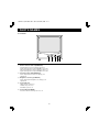
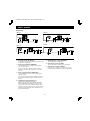
L8MAA/US (VMC-6609, 6612, 6615, 6620 GB) 2000. 11. 21
INSTRUCTION MANUAL
B/W Video Monitor
6609 (9 inch)
VM-6609
VM-6612
VM-6614
VM-6619
6612 (12 inch)
6614 (14 inch)
6619 (19 inch)
About this manual
• Before installing and using this unit, please read this manual carefully. Be sure to keep it handy for later reference.
• This manual gives basic connections and operating instructions for 4 models (VM-6609, 6612, 6614 and 6619).
L8MAA/US (VMC-6609, 6612, 6615, 6620 GB) 2000. 11. 21
INFORMATION TO USER
FCC COMPLIANCE STATEMENT
WARNING:
TO REDUCE THE RISK OF FIRE OR ELECTRIC
SHOCK, DO NOT EXPOSE THIS PRODUCT TO RAIN
OR MOISTURE.
DO NOT INSERT ANY METALLIC OBJECT THROUGH
THE VENTILATION GRILLS.
FCC INFORMATION: THIS EQUIPMENT HAS BEEN
TESTED AND FOUND TO COMPLY WITH THE
LIMITS FOR A CLASS A DIGITAL DEVICE,
PURSUANT TO PART 15 OF THE FCC RULES.
THESE LIMITS ARE DESIGNED TO PROVIDE
REASONABLE PROTECTION AGAINST HARMFUL
INTERFERENCE WHEN THE EQUIPMENT IS
OPERATED IN A COMMERCIAL ENVIRONMENT.
THIS EQUIPMENT GENERATES, USES, AND CAN
RADIATE RADIO FREQUENCY ENERGY AND IF
NOT INSTALLED AND USED IN ACCORDANCE
WITH THE INSTRUCTION MANUAL, MAY CAUSE
HARMFUL INTERFERENCE TO RADIO
COMMUNICATIONS. OPERATION OF THIS
EQUIPMENT IN A RESIDENTIAL AREA IS LIKELY TO
CAUSE HARMFUL INTERFERENCE IN WHICH CASE
THE USER WILL BE REQUIRED TO CORRECT THE
INTERFERENCE AT HIS OWN EXPENSE.
CAUTION
RISK OF ELECTRIC SHOCK
DO NOT OPEN
CAUTION: TO REDUCE THE RISK OF ELECTRIC
SHOCK.
DO NOT REMOVE COVER (OR BACK).
NO USER-SERVICEABLE PARTS INSIDE.
REFER SERVICING TO QUALIFIED SERVICE
PERSONNEL.
Explanation of graphical Symbols
The lightning flash with arrowhead symbol,
within an equilateral triangle, is intended to
alert the user to the presence of
uninsulated “dangerous voltage” within the
product’s enclosure that may be of
sufficient magnitude to constitute a risk of
electric shock to persons.
CAUTION: CHANGES OR MODIFICATIONS NOT
EXPRESSLY APPROVED BY THE PARTY
RESPONSIBLE FOR COMPLIANCE COULD VOID
THE USER’S AUTHORITY TO OPERATE THE
EQUIPMENT.
THIS CLASS A DIGITAL APPARATUS MEETS ALL
REQUIREMENTS OF THE CANADIAN
INTERFERENCE-CAUSING EQUIPMENT
REGULATIONS.
The exclamation point within an equilateral
triangle is intended to alert the user to the
presence of important operating and
maintenance (servicing) instructions in the
literature accompanying the product.
CET APPAREIL NUMÉRIQUE DE LA CLASSE A
RESPECTE TOUTES LES EXIGENCES DU
RÈGLEMENT CANADIEN SUR LE MATÉRIEL
CAUSANT DES INTERFÉRENCES.
1
L8MAA/US (VMC-6609, 6612, 6615, 6620 GB) 2000. 11. 21
IMPORTANT SAFEGUARDS
1. READ INSTRUCTIONS -- All the safety and operating
12. LIGHTNING -- For added protection for video monitor or
instructions should be read before the appliance is operated.
equipment during a lightning storm, or when it is left
unattended and unused for long periods of time, unplug it
from the wall outlet and disconnect the antenna or cable
system. This will prevent damage to the video product due
to lightning and power-line surges.
2. RETAIN INSTRUCTIONS -- The safety and operating
instructions should be retained for future reference.
3. CLEANING -- Unplug video monitor or equipment from the
wall outlet before cleaning. Do not use liquid cleaners or
aerosol cleaners. Use a damp cloth for cleaning.
13. OVERLOADING -- Do not overload wall outlets and
extension cords as this can result in a risk of fire or electric
shock.
4. ATTACHMENT -- Do not use attachments not
recommended by the video monitor or equipment
manufacturer as they may result in the risk of fire, electric
shock or injury to persons.
14. OBJECT AND LIQUID ENTRY -- Never push objects of any
kind into video monitor or equipment through openings as
they may touch dangerous voltage points or short-out parts
that could result in a fire or electric shock. Never spill liquid
of any kind on the product.
5. WATER AND MOISTURE -- Do not use the video monitor
or equipment near water -- for example, near a bathtub,
washbowl, kitchen sink, laundry tub, in a wet basement, or
near a swimming pool, or the like.
15. SERVICING -- Do not attempt to service video monitor or
equipment yourself as opening or removing covers may
expose you to dangerous voltage or other hazards. Refer all
servicing to qualified service personnel.
6. ACCESSORIES -- Do not place video monitor or equipment
on an unstable cart, stand or table. The video monitor or
equipment may fall, causing serious injury to a child or
adult, and serious damage to the equipment. Wall or shelf
mounting should follow the manufacturer’s instructions, and
should use a mounting kit approved by the manufacturer.
16. DAMAGE REQUIRING SERVICE -- Unplug video monitor
or equipment from the wall outlet and refer servicing to
qualified service personnel under the following conditions.
A. When the power-supply cord or the plug has been
damaged.
B. If liquid has spilled, or objects have fallen into the video
product.
C. If the video product has been exposed to rain or water.
D. If the video product does not operate normally by
following the operating instructions, adjust only those
controls that are covered by the operating instructions as an
improper adjustment of other controls may result in damage
and will often require extensive work by a qualified
technician to restore the video product to its normal
operation.
E. If the video product has been dropped, or the cabinet
damaged.
F. When the video product exhibits a distinct change in
performance -- this indicates a need for service.
6A. Video monitor or equipment and cart
combinations should be moved with care. Quick
stops, excessive force, and uneven surfaces may
cause the equipment and cart combination to
overturn.
7. VENTILATION -- Slots and openings in the cabinet and the
back or bottom are provided for ventilation, and to ensure
reliable operation of the video monitor or equipment and to
protect it from overheating. These openings must not be
blocked or covered. The openings should never be blocked
by placing the video monitor or equipment on a bed, sofa,
rug, or other similar surface. Video monitor or equipment
should never be placed near or over a radiator or heat
register. Video monitor or equipment receiver should not be
placed in a built-in installation such as a bookcase unless
proper ventilation is provided.
8. POWER SOURCES -- Video monitor or equipment should
17. REPLACEMENT PARTS -- When replacement parts are
be operated only from the type of power source indicated on
the marking label. If you are not sure of the type of power
supplied to your home, consult your video monitor or
equipment dealer or local power company. For video
monitor or equipment designed to operate from battery
power refer to the operating instructions.
required, be sure the service technician has used
replacement parts specified by the manufacturer or that
have the same characteristics as the original parts.
Unauthorized substitutions may result in fire, electric shock
or other hazards.
18. SAFETY CHECK -- Upon completion of any service or
9. GROUNDING OR POLARIZATION -- This product is
repairs to this video product, ask the service technician to
perform safety checks to determine that the video product is
in proper operating condition.
equipped with a three-wire grounding-type plug, a plug
having a third (grounding) pin. This plug will only fit into a
grounding-type power outlet. This is a safety feature. If you
are unable to insert the plug into the outlet, contact your
electrician to replace your obsolete outlet. Do not defeat the
safety purpose of the grounding-type plug.
10. POWER CORDS -- Do not allow anything to rest on the
power cord. Do not locate video monitor or equipment
where the cord will be abused by persons walking on it.
11. HEED WARNINGS -- Follow all instructions marked on the
video monitor or equipment.
2
L8MAA/US (VMC-6609, 6612, 6615, 6620 GB) 2000. 11. 21
PRECAUTION
CONTENTS
If an abnormality does occur, turn the power switch off and
unplug the unit. Have a qualified technician perform any
repairs.
PARTS NAMES . . . . . . . . . . . . . . . . . . . . . . . . 4
Front Panel . . . . . . . . . . . . . . . . . . . . . . . . . 4
Do not use the monitor if it makes a strange noise,
emits a strange odor, or if smoke comes out from it
Rear Panel . . . . . . . . . . . . . . . . . . . . . . . . . 5
If used under these conditions, the monitor may cause a fire or
electric shock. Immediately unplug it and wait to make sure no
more smoke comes from it. Then take it to the dealer for service.
Do not try to repair or open the monitor yourself.
CONNECTION . . . . . . . . . . . . . . . . . . . . . . . . . 6
Single connection . . . . . . . . . . . . . . . . . . . 6
Multiple connection . . . . . . . . . . . . . . . . . 6
Do not allow the power cord to get damaged
• Do not place heavy objects on the power cord.
• Do not place the power cord near a heat source.
• Do not excessively bend the power cord, modify it, or secure
BASIC OPERATION . . . . . . . . . . . . . . . . . . . . 7
TROUBLESHOOTING . . . . . . . . . . . . . . . . . . . 8
it with staples.
Doing so may damage the power cord and cause a fire or
electric shock.
If the power cord is damaged, take it to the dealer and have it
replaced.
SPECIFICATIONS . . . . . . . . . . . . . . . . . . . . . . 9
FEATURES
Do not allow dust or dirt to build up on the
power cord or power outlet
A build-up of dust may cause a short circuit or generate heat
and cause a fire.
Be especially careful when using the monitor in areas of high
humidity, in areas with frequent condensation, in kitchens, and in
places where there is excessive dust.
Periodically unplug the power cord and clean away the dust that
builds up between the plug terminals.
• Universal power (AC 100V to AC 240V) and
Cautions when plugging in the power cord
• Horizontal resolution
detachable power cord
• 2 Channel Input - A/B Channel selectable
• Contrast, Bright control on front panel and
Sub-bright, V-size, V-hold control on rear panel
VM-6609, 6612: more than 800 TV line
VM-6614, 6619: more than 1000 TV line
• Make sure you insert the plug of the power cord all the way in
the power outlet. Using the monitor with the power cord not
fully plugged in may cause heat to generate and cause a fire.
• Do not use the monitor with the power cord wound or tied up.
Heat may generate and cause a fire.
• When using an extension cord, be sure that the total current load
of all equipment connected to it dose not exceed the specified
ratings of the extension cord. If the rating are exceeded, heat may
generate and cause a fire. Make sure to carefully read the
specifications accompanying the extension cord.
Cleaning
• Dirt can be removed from the cabinet by wiping it with a soft
cloth. To remove stains, wipe with a soft cloth moistened with
a soft detergent solution and wrung dry, then wipe dry with
dry soft cloth.
• Do not use benzine, thinner or other chemical product on the
cabinet, as that may cause deformation and paint peeling.
Before using a chemical cloth, make sure to read all
accompanying instructions. Make sure that no plastic or
rubber material comes in contact with the cabinet for a long
period of time, as that may cause damage or paint peeling.
SERVICE
This unit is a precision instruments and if treated with care, will
provide years of satisfactory performance. However, in the event
of a problem, the owner is advised not to attempt to make
repairs or open the cabinet. Servicing should always be referred
to your dealer or Sanyo Authorized Service Centre.
3
L8MAA/US (VMC-6609, 6612, 6615, 6620 GB) 2000. 11. 21
PARTS NAMES
Front Panel
1
1 Monitor Selector Switch (VIDEO A/B)
Turn this Monitor selector switch A position for a
signal fed through the rear panel VIDEO A connectors.
Then, turn this Monitor selector switch B position for a
signal fed through the rear panel VIDEO B connectors.
2 Contrast Control (» CONTRAST)
Turn to adjust picture contrast according to your
requirement.
3 Brightness Control (ã BRIGHT)
Turn to adjust picture brightness according to your
requirement.
4 Power Indicator
Lights when the power is on.
Lit: When the power is on.
Unlit: When power is off.
5 Power Switch (POWER)
Press this switch to turn the power on or off.
4
2
3 45
L8MAA/US (VMC-6609, 6612, 6615, 6620 GB) 2000. 11. 21
PARTS NAMES
Rear Panel
VM-6609
1
VM-6614
3
2
4
1
56
3
576
VM-6619
VM-6612
1
4 2
4 2
3
576
1
1 AC input socket (AC INPUT)
4 2
3
56
5 Sub-brightness control (SUB-BRI)
Connect the AC power cord (supplied) securely to this
socket and to a wall outlet.
Turn to adjust picture brightness.
6 Vertical Size control (V-SIZE)
2 Video input terminals (VIDEO IN)
Turn to adjust picture vertical size of the picture.
These terminals are used to input a video signal
source to this monitor.
Connect to the video output of a VCR or another
monitor (for loop through connection) or to a video
camera.
7 Vertical hold control (V-HOLD)
If the picture is scrolling up or down on the screen,
turn this control until there is a single steady picture.
3 Video output terminals (VIDEO OUT)
These terminals are used to output a video signal
from this monitor.
Loop-through output of the video in BNC connector,
then connect to the video input of another monitor or
a VCR.
4 Termination Switch (HI/75Ω (Lo))
Select the input impedance (HI/75Ω).
When using only one monitor, turn the termination
switch to the 75Ω position. When using more than
one monitor, set all of the termination switch on the
monitors to the HI position. However, the last monitor
termination switch should be in the 75Ω position for
proper line termination.
5
L8MAA/US (VMC-6609, 6612, 6615, 6620 GB) 2000. 11. 21
CONNECTION
Before connecting your system, make sure that all units are turned off.
The picture signal source can be connected to either the A or B terminal at the rear of the monitor. The monitor selector
switch at the front of the monitor can be used to select the input terminal used.
Single Connection
To Video B
INPUT terminal
(Video signal cable)
Monitor
To Video A
INPUT terminal
Monitor
To Video input
terminal
(Video signal cable)
Video recorder
To Video input
terminal
Video recorder
Video camera
(Rear panel)
Note: The components and connection cables are not included and must be purchased separately.
Multiple Connection
Multi-connection is possible using the loop-through feature of this unit.
When this monitor is connected to additional monitors, the same picture can be obtained on all the connected monitors.
Set the final monitor to 75 Ω termination state.
Coaxial cable
To Video input terminal
Monitor
Video recorder
Video camera
Note:
• Do not leave a unused cable and do not connect BNC connector to the last jack of the monitor. Only once connection.
• The components and connection cables are not included and must be purchased separately.
6
L8MAA/US (VMC-6609, 6612, 6615, 6620 GB) 2000. 11. 21
BASIC OPERATION
1
Press the POWER switch to turn on the power.
ON: The power is turned on (the POWER indicator is lit).
OFF: The power is turned off (the POWER indicator is off).
2
Select the picture input.
Use the monitor selector switch at the front of the monitor to select the picture being input to either the A or B input
terminal.
NOTE: If there is no input source connected to either the A or B input terminal, no picture will appear when that input
terminal is selected.
3
Adjust the picture.
Adjusting the picture brightness
Turn the BRIGHT control to the left or right to adjust the picture brightness.
Right: The picture becomes brighter
Left: The picture becomes darker
Adjusting the picture contrast
Turn the CONTRAST control to the left or right to adjust the picture contrast.
Right: The picture becomes sharper
Left: The picture becomes softer
7
L8MAA/US (VMC-6609, 6612, 6615, 6620 GB) 2000. 11. 21
TROUBLESHOOTING
Solutions to common problems related to your monitor are described here. If none of the solutions presented
here solves the problem, unplug the monitor and consult a SANYO-authorized dealer or service center for
assistance.
Problems
Points to be checked
Measures (Remedy)
No power supply.
Is the power plug loosened or disconnected?
Firmly insert the power plug.
No picture with the
power on.
Is the video signal output from the connected
component?
Set the connected component correctly.
Is the input signal selected properly?
Select the required video signal input with
the Monitor selector switch. (See page 4.)
Is the video cable disconnected?
Connect the video signal cable firmly. (See
page 6.)
Shaking picture.
Is the monitor close to a device generating a
strong magnetic field?
Move the device away from the monitor until
the picture stabilizes.
Picture is too
bright and hard to
view.
Has the termination switch been set
correctly?
Move the termination switch to the correct
setting.
The following are not malfunctions:
• You experience a mild electric shock when you touch the picture tube. This phenomenon is due to a normal buildup of
static electricity on the CRT and is not harmful.
• The monitor emits a strange sound when the room temperature changes suddenly. This is only a problem if an
abnormality appears on the screen as well.
• If two or more monitors are operated next each other, their images may shake or be distorted. This phenomenon is
due to mutual interference; it is not a malfunction.
Move the monitors away from each other until the interference disappears or turn the power off on any monitor that is
not being used.
8
L8MAA/US (VMC-6609, 6612, 6615, 6620 GB) 2000. 11. 21
SPECIFICATIONS
VM-6609
System
Picture tube
Resolution
Scanning frequency
VM-6612
VM-6614
VM-6619
EIA standard
9" measured
12" measured
15" measured
20" measured
diagonally, 90˚
diagonally, 90˚
diagonally, 90˚
diagonally, 90˚
deflection angle
deflection angle
deflection angle
deflection angle
More than 800 TV lines (center)
More than 1000 TV lines (center)
Horizontal: 15.75 kHz (EIA)
Vertical: 60 Hz (EIA)
Input terminals
VIDEO A
Composite video: 1 line, BNC connector, 1.0 Vp-p 75 Ω negative sync
VIDEO B
Composite video: 1 line, BNC connector, 1.0 Vp-p 75 Ω negative sync
Output terminals
VIDEO A
Composite video: 1 line, BNC connector, 1.0 Vp-p 75 Ω negative sync
VIDEO B
Composite video: 1 line, BNC connector, 1.0 Vp-p 75 Ω negative sync
Sub Adjusting control Sub bright volume
Yes
Yes
Yes
Vertical size volume
Yes
Yes
Yes
–
Vertical hold volume
Yes
No
Termination switch
Manual switchable Hi/75 Ω (Lo)
Operating
Temperature: –10 to 40˚C, Humidity: 10 % to 90 %
environment
Power Source
AC 100 V ~ 240 V 50/60 Hz
Power consumption 20 W
30 W
35 W
36 W
Dimensions (W x H x D) 222 x 238 x 250 mm
304 x 320 x 310 mm
350 x 350 x 360 mm
472 x 450 x 360 mm
Weight
4.5 kg
7.5 kg
11 kg
19 kg
Accessory
AC power cord x 1
Features and specifications are subject to change without prior notice or obligations.
Example: VM6609
D
H
W
9
L8MAA/US (VMC-6609, 6612, 6615, 6620 GB) 2000. 11. 21
SANYO INDUSTRIAL VIDEO
VIDEO MONITOR LIMITED WARRANTY
OBLIGATIONS
In order to obtain warranty service, the product must be delivered to and picked up from an Authorized Sanyo Service Center at the user’s
expense, unless specifically stated otherwise in this warranty. The names and addresses of Authorized Sanyo Service Centers may be
obtained by calling the toll-free number listed below.
For product operation, authorized service center referral, service assistance or problem resolution, call
CUSTOMER INFORMATION 1-800-421-5013
Weekdays 8:30 AM – 5:00 PM Pacific Time
For accessories and/or parts, call
PARTS ORDER INFORMATION 1-800-726-9662
Weekdays 8:30 AM – 5:00 PM Pacific Time
THIS WARRANTY IS VALID ONLY ON SANYO PRODUCTS PURCHASED OR RENTED IN THE UNITED STATES OF AMERICA,
EXCLUDING ALL U.S. TERRITORIES AND PROTECTORATES. THIS WARRANTY APPLIES ONLY TO THE ORIGINAL RETAIL
PURCHASER OR END-USER. THE ORIGINAL DATED BILL OF SALE, SALES SLIP OR RENTAL AGREEMENT MUST BE SUBMITTED
TO THE AUTHORIZED SANYO SERVICE CENTER AT THE TIME WARRANTY SERVICE IS REQUESTED.
Subject to the OBLIGATIONS above and EXCLUSIONS below, SANYO Fisher Company warrants this SANYO product against defects in
materials and workmanship for the periods specified below. SFC will repair or replace (at its option) the product and any of its parts which fail
to conform to this warranty. The warranty period commences on the date the product was first purchased or rented at retail.
LABOR
PARTS
PICTURE TUBE
1 YEARS
1 YEARS
1 YEARS
EXCLUSIONS
This warranty does not cover (A) the adjustment of customer-operated controls as explained in the appropriate model’s instruction manual, or
(B) the repair of any product whose serial number has been altered, defaced or removed.
This warranty shall not apply to the cabinet or cosmetic parts, batteries or routine maintenance.
This warranty does not apply to uncrating, setup, installation, removal of the product for repair or reinstallation of the product after repair.
This warranty does not apply to repairs or replacements necessitated by any cause beyond the control of SFC including, but not limited to, any
malfunction, defect or failure caused by or resulting from unauthorized service or parts, improper maintenance, operation contrary to furnished
instructions, shipping or transit accidents, modification or repair by the user, abuse, misuse, neglect, accident, incorrect power line voltage,
fire, flood or other Acts of God, or normal wear and tear.
The foregoing is in lieu of all other expressed warranties and SFC does not assume or authorize any party to assume for it any other
obligation or liability.
SFC DISCLAIMS ALL OTHER WARRANTIES EXPRESS OR IMPLIED, WITH REGARD TO THIS PRODUCT (INCLUDING THE
WARRANTIES OF MERCHANTABILITY AND FITNESS). IN NO EVENT SHALL SFC BE LIABLE FOR ANY SPECIAL, INCIDENTAL OR
CONSEQUENTIAL DAMAGES ARISING FROM THE OWNERSHIP OR USE OF THIS PRODUCT OR FOR ANY DELAY IN THE
PERFORMANCE OF ITS OBLIGATIONS UNDER THIS WARRANTY DUE TO CAUSES BEYOND ITS CONTROL. SFC’S LIABILITY FOR
ANY AND ALL LOSSES AND DAMAGES RESULTING FROM ANY CAUSE WHATSOEVER, ARISING OUT OF OR IN CONNECTION
WITH THE SALE, USE OR OWNERSHIP OF THIS PRODUCT INCLUDING WARRANTOR’S NEGLIGENCE, ALLEGED DAMAGED OR
DEFECTIIVE GOODS, WHETHER SUCH DEFECTS ARE DISCOVERABLE OR LATENT, SHALL IN NO EVENT EXCEED THE
PURCHASE PRICE OF THE PRODUCT.
ATTENTION
For your protection in the event of theft or loss of this product, please fill in the information below for you own personal records.
Model No. _____________________________________________
Serial No.______________________________________________
(Located on back or bottom side of unit.)
Date of Purchase _______________________________________
Purchase Price _________________________________________
Where Purchased _________________________________________________________________________________________________