1
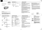
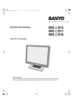
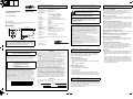
L5BG2_US(VCC-4794)(ENGLISH).fm
English
Français
1 ページ 2005年8月24日 水曜日 午前11時39分
Español
SPECIFICATIONS
VCC-4794
INSTRUCTION MANUAL
(Warranty attached)
Scanning system
Image sensor
Number of effective pixels
Horizontal resolution
Minimum illumination
(approx.)
Color CCD Camera
Video output
Video S/N ratio
Backlight compensation
About this manual
Before installing and using the camera, please read this manual carefully.
Be sure to keep it handy for later reference.
a DIMENSIONS
67 (2.64)
136 (5.35)
127 (5.0)
1 (0.04)
54 (2.13)
3 (0.12)
11 (0.43)
28 (1.10)
15.4
(0.61)
24.4 (0.96)
1/4”-20 UNC
Unit: mm (inch)
Depending on the conditions of use, installation and environment,
please be sure to make the appropriate settings and adjustments.
If you need help with installation and/or settings, please consult
your dealer or an Authorized Sanyo Service Center.
White balance
Gain control
Light control
Lens mount
Flange back
Aperture compensation
Sync system
Day/Night mode
Operating Environment
Power supply
Power consumption
(approx.)
Weight (approx.)
:
:
:
:
NTSC standard 525 lines, 60 fields/sec.
1/3" interline transfer method CCD
768 (H) x 494 (V)
More than 520 TV lines
: Gain high: 0.01 lx (F 1.2, B/W mode),
0.45 lx (F1.2, color mode)
Gain normal: 0.02 lx (F 1.2, B/W mode),
0.6 lx (F1.2, color mode)
: 1.0 V(p-p)/75 Ω, composite, BNC
: More than 48 dB (AGC off: More than 50 dB)
: OFF, Multi-spot metering (Normal/High), Center zone
metering
: ATW/Manual
: Normal/High
: Optical auto iris lens/Electronic iris (indoor use)
: CS mount
: 12.5 mm ± 0.5 mm adjustment
: Normal/Sharp
: Internal sync/Line lock
: Auto (Low/High), Manual (at CONTROL terminal)
: Temperature: –10°C – +50°C (14°F – 122°F)
Humidity: less than 90 % RH (no condensation)
: 24 V AC ±10%, 60 Hz/ 12 – 15 V DC
INFORMATION TO USER
Safety Guard
THIS SYMBOL INDICATES THAT THERE ARE IMPORTANT
OPERATING AND MAINTENANCE INSTRUCTIONS IN THE
LITERATURE ACCOMPANYING THIS UNIT.
WARNING:
TO PREVENT THE RISK OF FIRE OR ELECTRIC SHOCK, DO NOT
EXPOSE THIS APPLIANCE TO RAIN OR MOISTURE.
For the customers in Canada
This Class B digital apparatus complies with Canadian ICES-003.
Pour la clientèle canadienne
Cet appareil numerique de la Classe B est conforme à la norme
NMB-003 du Canada.
This installation should be made by a qualified service person and should
conform to all local codes.
This equipment has been tested and found to comply with the limits for a Class B
digital device, pursuant to Part 15 of the FCC Rules.
These limits are designed to provide reasonable protection against harmful
interference in a residential installation. This equipment generates, uses, and can
radiate radio frequency energy and, if not installed and used in accordance with the
instructions, may cause harmful interference to radio communications.
However, there is no guarantee that interference will not occur in a particular
installation. If this equipment does cause harmful interference to radio or television
reception, which can be determined by turning the equipment off and on, the user
is encouraged to try to correct the interference by one or more of the following
measures:
– Reorient or relocate the receiving antenna.
– Increase the separation between the equipment and receiver.
– Connect the equipment into an outlet on a circuit different from that to which the
receiver is connected.
– Consult the dealer or an experienced radio/TV technician for help.
This device complies with Part 15 of the FCC Rules. Operation is subject to the
following two conditions: (1) This device may not cause harmful interference, and
(2) this device must accept any interference received, including interference that
may cause undesired operation.
Changes or modifications not expressly approved by Sanyo may void the user's
authority to operate this camera.
: 3.7 W (with auto-iris lens)
: 400 g (14.1 oz) (without lens)
Appearance and specifications are subject to change without prior notice
or obligations.
Printed on recycled paper
SANYO Electric Co., Ltd.
1AC6P1P2978-L5BG2/US (0805KP-SY)
Printed in Japan
TROUBLESHOOTING
SANYO INDUSTRIAL VIDEO
COLOR CCD CAMERA LIMITED WARRANTY
OBLIGATIONS
In order to obtain warranty service, the product must be delivered to and picked up
from an Authorized Sanyo Service Center at the user's expense, unless specifically
stated otherwise in this warranty. The names and addresses of Authorized Sanyo
Service Centers may be obtained by calling the toll-free number listed below.
For product operation, authorized service center referral, service assistance or
problem resolution, call
CUSTOMER INFORMATION 1-800-421-5013
Weekdays 8:30 AM - 5:00 PM Pacific Time
For accessories and/or parts, call
PARTS ORDER INFORMATION 1-800-726-9662
Weekdays 8:30 AM - 5:00 PM Pacific Time
THIS WARRANTY IS VALID ONLY ON SANYO PRODUCTS PURCHASED OR
RENTED IN THE UNITED STATES OF AMERICA, EXCLUDING ALL U.S.
TERRITORIES AND PROTECTORATES. THIS WARRANTY APPLIES ONLY TO
THE ORIGINAL RETAIL PURCHASER OR END-USER. THE ORIGINAL DATED
BILL OF SALE, SALES SLIP OR RENTAL AGREEMENT MUST BE SUBMITTED
TO THE AUTHORIZED SANYO SERVICE CENTER AT THE TIME WARRANTY
SERVICE IS REQUESTED.
Subject to the OBLIGATIONS above and EXCLUSIONS below, SANYO Fisher
Company warrants this SANYO product against defects in materials and
workmanship for the periods specified below. SFC will repair or replace (at its option)
the product and any of its parts which fail to conform to this warranty. The warranty
period commences on the date the product was first purchased or rented at retail.
LABOR
PARTS
IMAGE DEVICE
3 YEARS
3 YEARS
3 YEARS
EXCLUSIONS
This warranty does not cover (A) the adjustment of customer-operated controls as
explained in the appropriate model's instruction manual, or (B) the repair of any
product whose serial number has been altered, defaced or removed.
This warranty shall not apply to the cabinet or cosmetic parts, batteries or routine
maintenance.
This warranty does not apply to uncrating, setup, installation, removal of the product
for repair or reinstallation of the product after repair.
This warranty does not apply to repairs or replacements necessitated by any cause
beyond the control of SFC including, but not limited to, any malfunction, defect or
failure caused by or resulting from unauthorized service or parts, improper
maintenance, operation contrary to furnished instructions, shipping or transit
accidents, modification or repair by the user, abuse, misuse, neglect, accident,
incorrect power line voltage, fire, flood or other Acts of God, or normal wear and tear.
The foregoing is in lieu of all other expressed warranties and SFC does not assume
or authorize any party to assume for it any other obligation or liability.
SFC DISCLAIMS ALL OTHER WARRANTIES EXPRESS OR IMPLIED, WITH
REGARD TO THIS PRODUCT (INCLUDING THE WARRANTIES OF
MERCHANTABILITY AND FITNESS). IN NO EVENT SHALL SFC BE LIABLE FOR
ANY SPECIAL, INCIDENTAL OR CONSEQUENTIAL DAMAGES ARISING FROM
THE OWNERSHIP OR USE OF THIS PRODUCT OR FOR ANY DELAY IN THE
PERFORMANCE OF ITS OBLIGATIONS UNDER THIS WARRANTY DUE TO
CAUSES BEYOND ITS CONTROL. SFC'S LIABILITY FOR ANY AND ALL LOSSES
AND DAMAGES RESULTING FROM ANY CAUSE WHATSOEVER, ARISING OUT
OF OR IN CONNECTION WITH THE SALE, USE OR OWNERSHIP OF THIS
PRODUCT INCLUDING WARRANTOR'S NEGLIGENCE, ALLEGED DAMAGED OR
DEFECTIIVE GOODS, WHETHER SUCH DEFECTS ARE DISCOVERABLE OR
LATENT, SHALL IN NO EVENT EXCEED THE PURCHASE PRICE OF THE
PRODUCT.
ATTENTION
Before sending the camera out for repair, check the items below.
If the problem persists after checking these items, consult your
dealer or an Authorized Sanyo Service Center.
■ If no image appears
• Is the coaxial cable attached securely?
• Are the power and voltage normal?
• Has the iris of the lens been adjusted correctly (with the LEVEL
dial)?
• Is there adequate illumination?
■ If the image is unclear
•
•
•
•
Is the monitor adjusted correctly?
Is the flange-back position correctly set?
Is the lens in focus?
Is the lens clean?
Dirt or fingerprints on the lens can adversely affect the image.
Gently wipe any dirt or fingerprints off the lens with a soft cloth or
lens cleaning paper and cleaning fluid (commercially available).
SERVICE
For your protection in the event of theft or loss of this product, please fill in the
information below for you own personal records.
Model No.
Serial No.
(Located on back or bottom side of unit.)
Date of Purchase
Purchase Price
Where Purchased
The camera is a precision instrument. Handle it carefully and always
follow the safety precautions. If the camera requires service, never
try to repair it yourself or open the casing.
For servicing, maintenance, or repairs, consult your dealer or an
Authorized Sanyo Service Center.
PRECAUTIONS
■ In case of a problem
Do not use the unit if smoke or a strange odor comes from the unit,
or if it seems not to function correctly. Turn off the power
immediately and disconnect the power cord, and then consult your
dealer or an Authorized Sanyo Service Center.
■ Do not open or modify
Do not open the cabinet, as it may be dangerous and cause damage
to the unit. For repairs, consult your dealer or an Authorized Sanyo
Service Center.
■ Do not put objects inside the unit
Make sure that no metal objects or flammable substance get inside
the unit. If used with a foreign object inside, it could cause a fire, a
short-circuit or damage. Be careful to protect the unit from rain, sea
water, etc. If water or liquid gets inside the unit, turn off the power
immediately and disconnect the power cord, and then consult your
dealer or an Authorized Sanyo Service Center.
■ Be careful when handling the unit
To prevent damage, do not drop the unit or subject it to strong shock
or vibration.
■ Do not install this unit close to magnetic fields
The magnetic fields may result in unstable operation.
■ Protect from humidity and dust
To prevent damage, do not install the unit where there is greasy
smoke or steam, where the humidity may get too high, or where
there is a lot of dust.
■ Protect from high temperatures
Do not install close to stoves, or other heat sources, such as
spotlights, etc., or where it could be subject to direct sunlight, as this
could cause deformation, discoloration or other damages.
Be careful when installing close to the ceiling, in a kitchen or boiler
room, as the temperature may rise to high levels.
■ Cleaning
• Dirt can be removed from the cabinet by wiping it with a soft cloth.
To remove stains, wipe with a soft cloth moistened with a soft
detergent solution and wrung dry, then dry by wiping with a soft
cloth.
• Do not use benzine, thinner or other chemical products on the
cabinet, as this may cause deformation and paint peeling. Before
using a chemical cloth, make sure to read all accompanying
instructions. Make sure that no plastic or rubber material comes
into contact with the cabinet for a long period of time, as this may
cause damage or paint peeling.
L5BG2_US(VCC-4794)(ENGLISH).fm
2 ページ 2005年8月24日 水曜日 午前11時39分
Español
Français
English
CONNECTIONS AND ADJUSTMENTS
b Attaching the lens
b Camera attachment
b Flange-back adjustment
Use any DC type and CS mounting lens equipped with an auto iris (sold separately).
When attaching the camera, make sure to verify that the attachment surface will allow full
tightening of the screws. Plaster board, etc., may not give a strong enough attachment, and
it is recommended to use a reinforcement, or other method so that the screws are anchored
securely.
This normally does not need adjustment. If the picture is out of focus at the telephoto position,
adjust the flange-back position as described below.
1
2
3
5 mm max.
• Depending on the type of the lens, the shape of
the lens plug may differ. In this case, consult your
dealer or an Authorized Sanyo Service Center.
• Apply adapter ring (sold separately) when you use
any C mounting lens.
Pin layout for LENS terminal
Brake coil (–)
Drive coil (+)
Brake coil (+)
Drive coil (–)
POWER VIDEO
OUT
CONTROL
LINE
PHASE
CBG
AC24V
DC12V
b Supported coaxial cables
b Camera adjustments/settings
<C-BW> Day/Night function switchover point
The camera comes pre-adjusted and ready to install at the time of
factory shipment, but you can make adjustments or settings if you
need.
This switch is used to set the timing for automatic switching
between color and black-and-white images.
If you have trouble adjusting the camera, consult your dealer or an
Authorized Sanyo Service Center.
H
H
S
M
C MWB LL
B/W
2
3
4
5
6
LSB L
N
N
1
MSB
7
OFF ATW INT
Use of an auto-iris lens
<DC 12 V connection>
RED
L
H
LEVEL
A. I.
LENS
BLUE
Use of a manual or fixed
iris lens (for indoor use)
GND AC24V
1
DC12V
Check that polarity is correct.
Tighten.
1
• Set the lens aperture to the shortest F-stop.
• When using a manual or fixed iris lens under fluorescent light, the
image may flicker.
• When using an auto-iris lens, if the entire image is too dark or too
bright, adjust the contrast by using the LEVEL dial.
B/W
Low
Only when using an auto-iris lens
Multi-spot metering
Backlight compensation
to the entire screen*
5
Normal
6
5
Color
Fixing the image to color
<GAIN> Auto gain control (AGC)
High sensitivity
Increased electronic sensitivity to obtain a
bright image in a lower illuminance*
Normal
sensitivity
3
3
* This setting causes noise generation and a grainy image.
<AP> Aperture compensation
Sharp outline
Normal outline
4
4
Fixing the image to back-and-white
CONTROL
6
5
OFF
5
6
6
<WB> White balance (color compensation)
• The color image will be displayed first when the power is turned on.
• When switching between color and black-and-white images
automatically, it is normal for movement of the optical filter to be
heard and for a vertical black band to move across the screen.
• Switching from black-and-white to color may occur if there is a
significant degree of reflection from the object when using infrared
illumination in black-and-white image. Adjust the illumination to
avoid switching to color image.
• The focus setting position may differ between color and
black-and-white images. Carry out adjustment to ensure that the
focus for both images is in the optimum position.
b When a hunting reaction occurs
Center zone metering
Backlight compensation
to the central portion of
the screen
* If the background of the object is extremely dark, set to Center zone
metering.
Switchover point
2
<BLC> Backlight
compensation
CONTROL
Auto-Tracing
White balance
Manual White Balance
Turn clockwise to
augment the color.
7
7
RED
BLUE
<SYNC> Sync setting
Line-Lock
(Only when using an AC power supply)
Synchronizes the unit with power
frequency*
Internal sync
LINE
PHASE
8
Under near infrared lighting or other similar conditions, hunting reaction may occur because the
Day/Night function is not carried out normally. In such case, refer to the following diagram for cable
connection to fix the image either to color or black-and-white by using an external switch, etc.
Set to the maximum
telephoto position and
focus the picture.
Loosen.
High
a Set the switchover point to darker side so that the automatic switch
may trip in darker condition for switchover between color and
black-and-white images.
8
ES/EI C-BW
AP BLC WB SYNC
GAIN
Color
Switchover point
2
<ES/EI> Iris setting
To prevent a fire hazard use any
UL listed wire rated VW-1.
a Set the switchover point to brighter side so that the automatic
switch may trip in brighter condition for switchover between color
and black-and-white images.
ON
• When using an RG-59U (3C-2V) cable, do not use it
on piping or air wiring.
<AC 24 V connection>
1
4
High
b Power cable
2
Set to the maximum
wide-angle position
and focus the picture.
Make sure to use the
screws to secure the
bracket.
Cable type – Length: RG-59U (3C-2V) – 250 m max.,
RG-6U (5C-2V) – 500 m max., RG-11U (7C-2V) – 600 m max.
• If you use a cable other than the type above, the
image or sync signal will be attenuated and will not be
transmitted correctly.
3
Changing the
bracket topside out
Repeat steps 2 and 3 until the image stays in-focus when changing from a wide-angle position to
a telephoto position.
LINE PHASE
dial
POWER lamp
GND
When monitoring lighting or other extremely bright objects (which
exceed the maximum required illumination), smearing may occur in
the vertical or horizontal direction (either above and below the
high-brightness object or as a perpendicular band). In such a case,
adjust the angle of illumination and other factors while observing
the monitor.
8
(Rear panel)
* Adjust the roll by turning the LINE PHASE dial on the second and
subsequent cameras.
If the vertical roll cannot be corrected by adjusting the LINE PHASE
dial on the second and subsequent cameras, try adjusting the LINE
PHASE dial on the first camera. If it still cannot be corrected, please
check that the polarity of the power cords of all connected devices is
correct.
<LEVEL> Lens iris level adjustment
When using an auto-iris lens, if the entire image is too dark or too
bright, adjust the contrast.
C B G
AWG24: 600 m max.
C B G
Low (darker)
High (brighter)
L
You cannot control the switchover operation by using an external switch, etc., while switching between
color and black-and-white images is actually in progress by the Day/Night function.
H
LEVEL
A. I.
LENS