1
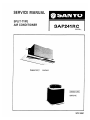
SERVICE MANUAL
SPLIT-TYPE
AIR CONDITIONER
AP241RC
(U.S.A.
[Indoor Unit | — SAP241R
ВОРОТ СОЧИ,
| Outdoor Unit |
SAP241C
WM-14967
SANYO
HVAC
LIMITED WARRANTY OF ORIGINAL PURCHASER
Sanyo Electric Inc. takes pride in its products and believes they are manufactured to the
highest possible standards. Consequently. Sanyo warrants to the original consumer its Air
Conditioner for one (1) year for parts only. Sanyo will repair or replace (at its option) at no
charge any part(s) found to be defective during the warranty period. In addition, Sanyo war-
rants the compressor for a total of five (5) years, and will cover labor charges on compressor
replacement only for a period of thirty (30) days.
OBLIGATIONS OF THE ORIGINAL OWNERS
Warranty repair must be performed by a qualified HVAC contractor. The dealer's original
dated bill of sale must be retained as proof of purchase and must be presented to the qualified
HVAC contractor.
EXCLUSIONS OF THE WARRANTY
line voltage, damage caused by improper installation, labor cost of removing or reinstalling of
product for repairs, improper or unauthorized repair, broken or marred cabinet, accessories,
knobs, filters, custmer adjustments which are not covered in instruction book.
Warranty is void and of no effect if serial numbers on the Sanyo product are missing or
altered. This warranty is valid on products purchased and used in the United States of
America only.
This is the entire Sanyo warranty and it may not he changed or amended by any person, agen-
cy, distributor, dealer, or company without prior written authority from Sanyo Electric Inc.,
and Sanyo does not authorize any party to assume for it any obligation or liability.
This warranty yives the consumer specific legal rights but he may have other legal rights
which may vary from state to state. In no event shall Sanyo be liable and specifically denies
responsibility for any consequential damages arising from the use of this product beyond the
repair or replacement of the Air Conditioner, or for any delay in the performance or this war-
ranty due to causes beyond our control.
Some states do not allow limitations on how long an impjlied warranty last and/or do not
allow the exclusuion or limitation of consequential damages, so the above limitations on im-
plied warranty and consequential damages may not apply to you.
Should the consumer need repairs or assistance in locating his nearest qualified HVAC con-
tractor, contact dealer of purchase or call/write to Sanyo Electric Inc. as follows:
Sanyo Electric Inc.
200 Riser Road
Little Ferry, NJ 07643
(201) 641-2333
SANYO SPLIT-TYPE AIR CONDITIONER
SERVICE MANUAL
MODEL: SAP241RC
— Table of Contents —
Page
1. SPECIFICATIONS .............sssaaanccrorecasasensran nana none nana nana ea AAA NA 0 0000000000 0000 SEE EE 00000000 1
1.1 Unit Specifications ...….....................ererranare ren senc ere ce nan ns ana ama eme a na anna a casa a AUCUN OUEN 1
1.2 Major Component Specifications .....................…….....sresersansencran ame nn nana caca a cannes 2
1.3 Compressor Identification ................ecrre.eeresceserrerirerernecener ere cren eee. 4
2. CONSTRUCTION OF THE UNIT .............eeceeenreuavacoanecccaaoaccanrecoreeneervenevene oceano 5
3. DIMENSIONAL DATA ..........e.eeenenanoocarrercavecavareatueroavanrenmecanenecenenacaneetonreneamenormar: 6
4. PERFORMANCE CHARTS ..............eeenecarreveranaccrooveosonereeneneseneocarereneoomenmesvecon mes 8
5. OPERATING INSTRUCTIONS ..............ereennennecocencorenconrerenecaaccaaeerenneroreucame encarnan 10
6. INSTALLATION INSTRUCTIONS ...........e.eeessccocccrorianeecenoroneoeaccacsecao eremaccaneno 12
7. TROUBLESHOOTING -..............e..e2esvoncraraacsconeaenenancoeoveveorovananeaaae rene ananecanocanmem.. 27
8. CHECKING AND REPLACING ELECTRICAL COMPONENTS ever nenn 38
9. DISASSMBLY AND SERVICE PROCEDURES ..................eseaunuccorennecceeeeamenccanenene 47
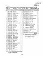
10. PARTS LIST -...............eeeceecccurveroccccarerenacecererveevere retener o nece nonanecaaneocanee nenes 63
11. REFRIGERANT FLOW DIAGRM ............e.ecesnrvansooroooccaccevaoooaareacaccancerveraia nena nen 67
12. ELECTRIC WIRING DIAGRAM .............eeercenrcenvocaacccarenencereenecannecanenen eones 68
13.
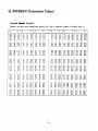
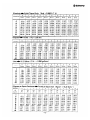
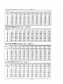
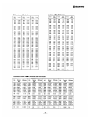
APPENDIX (Conversion Tables) .................e.eennsacurorrconceocerenoomasecaseosonesaanec eee. 71
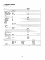
1. SPECIFICATIONS
1.1 Unit Specifications
Model No. SAP241RC
Unit Model No. Indoor unit SAP241R
Outdoor unit SAP241C
PERFORMANCE & ELECTRICAL RATINGS
Capacity — Cooling BTU/hr. 23,800/23,400
— Heating BTU/hr. —
Moisture Removal (High) Pints/hr. 8.4
Air Circulation (High) Cu.ft./min. 565/530
SEER (EER) BTU/Whr. 8.1/8.3 (7.85/7.9)
COP —
Frequency Hz 60
Rated Voltage Vv 230/208
Running Amps A 13.6/14.4
Power Input WwW 3,030/2,960
Back-up Heater kW —
ee Rreaker) A 30
FEATURES
Controls Microcomputer —
IC Yes
Fan Speeds 2
Timer —
Ventilator —
Air Deflection Horizontal —
Vertical Manual
Air Filter Washable, easy access
Temperature Control IC thermostat
Compressor Rotary
Refrigerant (R22) lbs. (g) 5.74 (2,600)
Refrigerant Tubing Connec- Flare type
Refrigerant Line Length Ft. (m) 50 (15)
Max. Outdoor Unit Height Ft. (m) 33 (10)
Refrigerant Tube o.d.
Narrow Tube In. (mm) 1/4 (6.35)
Wide Tube In. (MM) 5/8 (15.88)
Drain Tube o.d. In. (MM) 3/4 (26.67)
Refrigerant Tubing Kit Optional
DIMENSIONS 6 WEIGHT Indoor Unit Outdoor Unit
Dimensions Height In. (mm) 19-1/4 (490) 30-1/8 (765)
Width In. (MM) 51-3/16 (1,300) 26-6/16 (670)
Depth In. (mm) 24-7/16 (620) 26-6/16 (670)
Net Weight Ibs. (kg) 99.2 (45) 176.4 (80)
Shipping Size Cu.ft. (cu.m) 19.8 (0.56) 18.0 (0.51)
Shipping Weight Ibs. (kg) 132 (66) 193.6 (88)
* Without electric heater
DATA SUBJECT TO CHANGE WITHOUT NOTICE
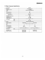
1.2 Major Component Specifications
2D SANYO
Unit Model No. SAP241C
Compressor Hermetic Rotary Type
Compressor Model No. C-R190H6N
Source 230/208 V, 60 Hz, Single Phase
Pole 2
Nominal Output (W) 1900
Displacement (cc/rev.) 41.6
Amps.-Full Load (A) 12.7/14.0
-Locked Rotor (A) 84 (240 V)
Type of Oil
Special oil for Rotary Compressor
Compressor Oil Amount (cc) 1,350
Coil Resistance (©) C-R: 0.66
(Ambient Temp. 77°F) C-S: 1.968
Protective Device Internal Protector (15HM2505)
Run Capacitor, MFD 35
VAC 370 or 400
Unit Model No. SAP241R | SAP241C
Fan Motor Capacitor Run induction Motor
Fan Motor Model No. KFG4S-81B6P | KFC8-101A6P
Source 230/208 V, 60 Hz, Single Phase
Pole 4 8
Nominal Qutput (W) 80 20
Amps.-Full Load (A) 0.83/0.77 0.5/0.5
-Locked Rotor (A)
Protective Device
Internal Protector (17AM031 A5—4)
Internal Protector (17AMO35 A5—4)
Run Capacitor, MFD 3 5
VAC 440
Coil Resistance (RQ) WHT-BRN: 55.2 WHT-BRN: 24.1
(Ambient Temp. 68°F) WHT-YEL: 53.2 WHT-PNK: 53.8
YEL-PNK: 74.6
Unit Model No. SAP241R Figure
Room Temp. Sensor* OCS5K-UL Incorporated in the remote
control unit
69°F: 6—6.5
Resistance (kS2) 86°F: 3.9—4.2
77°F: 4,9—5.2
Note: * = thermistor
Unit Model No. SAP241R Figure
Power Transformer (for Controller PCB) ATR-J122U
. Primary: WHT-NHT 143.5
Resistance (92) Secondary: BRN-BRN 1.2
Unit Model No. SAP241C Figure
Magnet Relay CLK-16E3-21 D
Unit Model No. SAP241C Figure
Crankcase Heater CH5700
<
Rating 230 V, 30 W «
Unit Model No. SAP241C Figure
Outdoor Coil Thermostat Y TB-4U201
Operating Temperature
ON: 75°F, OFF: 78°F
Unit Model No.
SAP241C
Solenoid Valve
NEV603DXFU (valve), NEVAC208 (coil)
Rating
230 V/208 V
5.5 W/5 W
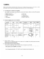
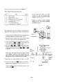
1.3. Compressor Identification
1. Marking (Stamped)
Compressor > 806 486 46 Manufacturer:
code No. /
T = Tokyo
Model No. » C — R190H6N S = Sanyo
E = Electric.
Production > 30 01 5 «———— (=30 Jan., 1985)
Date
Ratings (V) » V230/208
Frequency (Hz) > HZ60PH1
and Phase
2. Compressor Code No.
Voltage Identification
2: 115V AC, 60 Hz
6: 208/230VAC, 60Hz
Phase & Application
4: 1-PH & High Back Pressure
Design Serial No.
Figures to express
Nominal Output (Approx. Watts)
Figures to express
Compressor Type
(806 means ROTARY)
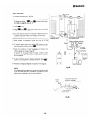
3. Compressor Wire Orientation
Discharge Tube
Compressor
5
Termina
AAN
COMPRESSOR
2 SANYO
® Printed marking
LOCKED ROTAR (AMP.)
THERMALLY
PROTECTED
® Warning label
Terminal
Component
Stamped Marking
Rotary Compressor
Mounting
Component
WARNING-SERVICEMAN
1. FIELD SERVICE LEAK TEST PRESSURE MUST
NOT EXCEED 150 P.S.1.G.
2. THIS COMPRESSOR MUST BE GROUNDED.
3. DO NOT OPERATE WITHOUT PROTECTIVE
COVER OVER TERMINALS: DISCONNECT ALL
POWER BEFORE REMOVING THE PROTECTIVE
COVER.
CAUTION
COMPRESSOR HOUSING MAY REACH 302°F (150°C)
WITH TERMNAL PROTECTOR APPROVED BY
TOKYO SANYO AND TESTED IN ACCORDANCE
WITH UL984-1981.
TOKYO SANYO ELECTRIC CO.,LTD.
Wiring Diagram
POWER
SUPPLY
©- МАМ
| WINDING
INTERNAL
PROTECTOR
AUX,
WINDING
RUNNING $
CAPACITOR COMPRESSOR
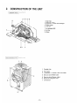
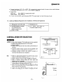
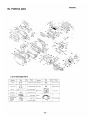
2. CONSTRUCTION OF THE UNIT
| INDOOR UNIT | SAP241R
OUTDOOOR UNIT | SAP241C
1
2
NOOR wh 2
. Drain hose
. Refrigerant tubing
. Evaporator (= Indoor heat exchanger)
Blower casing
Drain pan
Fan motor
. Air discharge panel
. Air filter
. Blower
WON HAWN =
Propeller fan
Fan motor
Condenser ( = Outdoor heat exchanger)
Service valve (Wide tube)
Service valve (Narrow tube)
Electrical component box
Compressor
2 SANYO
SAP241R
Indoor Unit
N
a
oo OANYS 6
NT
AWLSOMM IML
> ==,
N 68 UN ELE 53; . —
SH ~
3 DO exi ls
e 440 CIS NY
= NOILY W340
©
— a
[e >
|
СЕЛА "91/6 91/67
Xog (Alossagoy)
UN 02007) 1 OLE 3U80U0dW0 7983 d0laepe edd ujeiq esn
91/€-1 Ens a 91/е Ze/E1-DL N Ze/l-L 'a'o
ZE/ETY (ButuadQ Buia) 103) 91/EL-8 NE abieyosiy ‘adig uresg JAd
- ZENT YE 91/06 (3 \ [szemen] "Y YA
|, à mew | uy
Ez os X a
@ 1
зарпо bun замод ol = ©
= ze] 1 ~ IR
+ ais < 4
ala E
= =
o ки
Г 0
N
|
8/£-7 H Y
- — 7 MEL B/eZ N
BIEL бита adidapima/S — | Izc/s2* gr - y ”zesa egn| MOLEN $/L
ZE/6-CE CE/STEL irre. Tor
CEL 91/1161 -2£/61
Uog vorsuedsns JOj ajOH did uesQ (Buuedo Guia 104) 91/1-27
2€/S7 "Eq xp PE
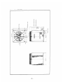
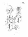
DIMENSIONAL DATA
3.
SAP 241C
Qutdoor Uni
191300 бынну замод
\
ha ————— ——— ——— ad
CE/L'97
pa ———
zE/12 AN
P/1-S BEZ |
т
91/6-5
8/€:5
91/22
"ie
e + $
ZE/E-0L
91/1-9€
BA[BA BsIAJAS 9QN | PIM B/G +
|
BARA 3D1A18G BQN | MOJIEN bf | Ju
lL +
|
1n0yJ0Uy
/ 7 BuistAA MHuniajU|
ИДО
быки 104 810H "BQ 25/51 Х ф
8/€-97
ZE/4Z
9L/1-SZ
“La |
2618 051G iy 0
т
axe лу >
8/€-97
91/1-57
Z£/LZ
ax) sty 0
ZE/L2
ayelu| ny
<<
~
26/092
Aia,
> SANYO
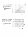
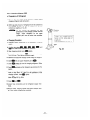
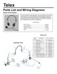
. oo 230 V (60) Hz
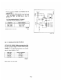
Cooling characteristics Model: SAP241RC 17 | |
|
. e i | OF °C
Operating current characteristics versus outdoor A 16
ambient temperature and indoor temperature 16 ! 1 198 090)
(Indoor relative humidity: 50%, indoor air - | 1 180 (27)
. |
velocity: High , overall value for indoor and | 14 | | HT 14H 75 28
- Г 1)
outdoor shown.) < | | LA LAN >>
+ | | LA LA
; S| 13 | | «В A LAT
NOTE: The solenoid valve opens to by-pass E | A LI ET
refrigerant flow when the outdoor am- al 12 EAT LTL
bient temperature stays within the dotted- Е B= HL
line range. 5) ul LH)
© | |
HT
10 |
| |
| |
68 77 86 95 104°F
(20) (25) (30) (35) (40)°C
Outdoor ambient temps.
208V (60)Hz
Cooling characteristics Model: SAP241RC 17 | oF oC
| | |_| 86 (30)
Operating current characteristics versus outdoor À 16 | | AT 80 (27)
ambient temperature and indoor temperature 15 | | Га 7 a
. ge . . | |
(Indoor relative humidity: 50%, indoor air | | AAA (
velocity: High , overal value for indoor and —| 14 | + A A
outdoor shown. |, | ATT
D 3 A — —
= |
NOTE: The solenoid valbe opens to by-pass 3 TT
refrigerant flow when the outdoor am- 2 1 —— >
bient temperature stays within the dotted- o A ++ |
Of 11 = |
line range. о LA |
+] | |
10 | |
|
| |
| |
68 77 86 95 104 °F
(20) (25) (30) (35) (40)°C
Outdoor ambient temps.
— ЧЩ
"Др
Cooling characteristics Model: SAP241RC
High pressure characteristics versus outdoor
ambient temperature and indoor temperature
(Indoor relative humidity: 50%, indoor
velocity: High.)
NOTE: The solenoid valbe
line range.
Cooling characteristics Model: SAP241RC
Low pressure characteristics versus outdoor
ambient temperature and indoor temperature
(Indoor relative humidity: 50%, indoor air
velocity: High.)
NOTE: The solenoid valbe opens to by-pass
refrigerant flow when the outdoor am-
bient temperature stays within the dotted-
line range.
opens to by-pass
refrigerant flow when the outdoor am-
bient temperature stays within the dotted-
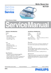
Suction pressure: at wide tube service valve
Discharge pressure: at high pressure gage port
230:208 V (60) Hz
OF °C
86 (30)
284. 46- ——— T T 7 .
(20) | | 1 80 127)
| MAN 75124)
T ] "а
| | A 70 (21)
|
256.02 ) A
A (18) | | AN A
i 7 ved
227.57-—-- , AAA
| Ea
(16) | ОИ
| AA
|
199.12- — — - A
(14) A
Le
ZZ
|
170.67 psig AA
2 i i
(12) kgrem? | A" | |
|
68 77 86 95 104%
(20) (25) (30) (35) (40) °С
Qutdoor ambient temps.
230/208 V (60) Hz
99.56 T T
(7) | |
| |
} |
AE
85.34 |
(6) | |
| |
7 |
| i
1 | OF °С
i i
7.12 | — 86 (30)
fod 11 = +] |"
PEER TT ня 1 75 (24)
Lo AAA | [Г лог
66 89—— = | e
a rT TTT
( Li | lt
-
ro i |
|
42.67 psig | я, ; =,
em? 68 77 5 F
(3) kgem 20 (25) (30) (35) (40)%C
)
Outdoor ambient temps.
de
“ра
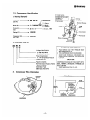
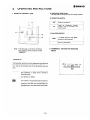
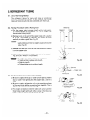
5. OPERATING INSTRUCTIONS
A. INDICATOR LAMP (Green)
This lamp lights up during fan only and cooling operation.
1. REMOTE CONTROL UNIT
Uy
I ||
| ee
| | FAN SPEED
e О
0
7° 33 75 77 79 8) BI BG 87 FAN
|
а | ||| T ||, D
a THERMOSTAT
2 SANYO | |
Note: If the lamp goes out and the air conditioner
stops operating, refer to the section entitled
“REMEDIES.”
THERMOSTAT
The thermostat maintains the room temperature automatically at
the desired level and ensures economical air conditioner opera-
tion. Just set the thermostat lever for the temperature level you
want,
TEST RUN: This position is to be used for test operation only
after installation or during service. Normally it
should be locked.
FAN: Set thermostat lever to this position when FAN
only operation is needed.
Note? The numbers on the graduated scale are meant to
serve as a guideline only. The actual room
temperature may differ from the thermostat set-
ting depending on room size and the cooling load.
—10—
ZA SANYO
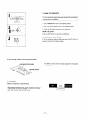
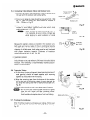
B. OPERATION SWITCH
OFF Stops air conditioner.
Starts air conditioner; bringing
ON cooling, room air circulation and
filtering dusts.
C. FAN SPEED SWITCH
HIGH To operate the fan at high speed,
set lever to HIGH position.
To operate the fan at low speed, set
LOW ди
tever to LOW position.
D. THERMOSTAT, FAN AND TEST RUN SLIDE
SWITCH
TEST
RUN 69 71 73 75 77 79 81 83 85 87 FAN
Ч
THERMOSTAT
2. HOW TO OPERATE
1 69 71 73 75 77 79 81 83 85 87 FAN
Turn on the power supply disconnect at least five hours before
| starting the air conditioner.
THERMOSTAT
1. Set THERMOSTAT lever to the desired position.
2. Set FAN SPEED selector lever to the desired position.
3. Press the ON button to start the air conditioner.
HIGH
LOW HOW TO STOP
Press the OFF button to stop the air conditioner.
EMERGENCY SHUTDOWN
OFF ON If the air conditioner does not stop even when the OFF button is
0 5 pressed, disconnect the power supply.
- |
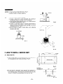
3. AIR FLOW DIRECTION ADJUSTMENT
Air deflector vanes can be manually adjusted for the desired
AIR DEFLECTOR VANE 4
air distribution.
CEILING PLATE
4. CAUTION
* SAFETY INTERVAL RESTARTING
RE-START
After pressing the OFF button, the air conditioner stops and
it will not start tor three (3) minutes. To start the unit again
after three minutes, press the ON button.
—11—
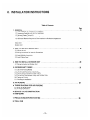
6.
INSTALLATION INSTRUCTIONS
Table of Contents
GENER AL Le eee ee ee ee ee 13
1-1. Tools Required for Installation (not supplied)
1-2. Accessories Supplied with Unit for Installation
1-3. Optional Copper Tubing Kit
1-4 Type of Copper Tubes and Insulation Material
1-5. Additional Materials Required to Give Installation a Professional Appearance
. INSTALLATION SITE SELECTION .............. ee eee eee as 14
Indoor Unit
Outdoor Unit
. HOW TO INSTALL INDOOR UNIT .......—.....e.erevrroonrerrrocnoccanoarercorarnareco, 15
3-1. Mount the unit
3-2. Wiring Instructions for Interunit Connections
3-3. Drain Piping
3-4, install Remote Control Unit
3-5. Install Ceiling Panel
. HOW TO INSTALL OUTDOOR UNIT i ee eee eee eee ee ees 20
4-1. Wiring Instruction on Outdoor Unit
REFRIGERANT TUBING |... i eee ee ee eee, 21
5-1. Use of the Flaring Method
5-2. Flaring Procedure with a Flaring Tool
5-3. Caution before Connecting Tubes Tightly
5-4. Connecting Tubes between Indoor and Cutdoor Units
5-5. Insulation of Refrigerant Tubing
5-6. Taping the Tubing
5-7. Finishing the Installation
6. AIR PURGING ............eamacrvorrerreaaeraracvvorerdaanaeoraaevarooaa PA 23
TUBING DIAGRAM FOR AIR PURGING
6-1. Quick Air Purge System
6-2. Air Purging Procedure
SERVICE VALVE CONSTRUCTION
PUMP DOWN
. PRECAUTIONS BEFORE STARTING RR 26
. TRIAL RUN
—12—
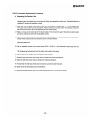
1. GENERAL
Here is a brief outline of where and how to install the unit. Please read over entire set of instructions for indoor
and outdoor units and make sure all accessory parts listed are with the unit before beginning.
1-1. Tools Required for Installation (not supplied)
Drill, 3-5/32" dia. hole saw or key hole saw for normal walls. However, chisels or core bits will be required
for brick, concrete, or similar walls.
e Regular Screwdriver e Tube Cutter
e Phillips Head Screwdriver e Flaring Tool
e Knife or Wire Stripper e Torque Wrench
e Level e Adjustable Wrench
e Tape Measure e Reamer or Small File
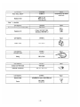
1-2. Accessories Supplied with Unit for Installation
Description Shape Q'ty Remarks Description Shape Q'ty Remarks
PVC etbow 670 1 Flanged hex nut ue |
For suspending
4 unit
PVC T-fitting 1 Special washer
For drain
piping
PVC pipe — 4 ;
Remote Install accessible
control 1 position
unit on the wall
PVC socket 0) 2
Pan-head screw M5 | 4 For ceiling panel |
Lead wire for Length of
Countersunk-head For remote a
wood screw (Day 2 control unit remote control 1 lead wire:
unit 10m
Drain Hose ao
adaptor O |
1-3. Optional Copper Tubing Kit
Copper tubing for connecting outdoor unit to indoor unit is available in kits which contain the narrow
and wide tubing, fittings and insulation.
1-4. Type of Copper Tubes and Insulation Material
If you wish to purchase these materials separately from a local source, you will need:
e Deoxidized annealed copper tube 1/4" outside dia. with a 0.0314” wall thiékness, and an equal length of
5/8” outside dia. with a 0.0394” wall thickness.
Cut to the appropriate lengths + 12” to 20” on each to dampen vibration between units.
—13—
ZA SANYO
e Foamed insulation 1/4" |.D., or 5/8” |.D. as required to precise length of copper tubing, wall thickness
of insulation should be 5/16” to 1/2” thick. (Refer to page 22)
e Copper Wire
Inter Unit: Min. AWG 14 in appropriate length.
Power Supply: Min. AWG 10
e 3 0.D. (1.D. 2-13/16, wall thickness 3/16") PVC pipe length to match thickness of wall.
1-5. Additional Materials Required to Give Installation a Professional Appearance
e Refrigeration (armored) tape e Refrigeration Oil
e Insulated staples or clamps ® 3-1/2" clamp — use 1 every 4 ft.
for connecting wire (To secure copper tubing).
(Refer to local codes)
e Putty (1/2 Ibs)
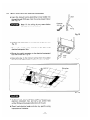
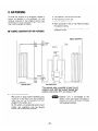
2. INSTALLATION SITE SELECTION ( E
y Ceiling
CU MMA UMA MMM AAA M AA A LA
Indoor Unit À 5 7
= И,
E 4” min, 7
AVOID: e areas where leakage of flammable gas may be expected. a 7
e places where large amounts of oil mist exist. 7
e direct sunlight. VS Gadde 777 wall,
e nearby heat sources that may affect performance of
the unit.
e locations where remote control will be splashed with la LL 7
water or affected by dampness or humidity. Г? Air Intake IM и
e installing remote control unit behind curtains or Air e
furniture that obstruct air circulation. discharge 7
2 min. 7
DO: e select an appropriate position from which every corner |
of the room can be uniformly cooled. O Fig. 1
e select a location that will hold the weight of the unit.
e select a location where tubing and drain pipe have
shortest run to the outside.
e allow room for operation and maintenance as well as
unrestricted air flow around the unit. Fig. 1 4
® allow room for mounting control unit about 4’ off the
floor, in an area that is not in direct sunlight or in the
flow of cool air from the unit. Tubing
e install unit within 33’ up or down of outdoor unit and length
within a total of 50’ from outdoor unit. Fig. 2 50' Max. difference
"Max.
|
Si
Ha
+
Hr] |
Уи
Elevation
a
HH
B13]
liam
HI
—14—
C Outdoor Unit 3
AVOID: e heat sources, exhaust fans, etc., Fig. 3
e damp, humid or uneven locations.
DO: e choose a place as cool as possible.
e choose a place that is well ventilated and outside air
temperature does not exceed 115° F constantly.
e allow enough room around unit for air intake/exhaust
and possible maintenance. Fig. 4
e provide a solid base; about 4” above ground level to
reduce humidity and possible water damage in unit and
decrease service life. Fig. 5
e use lug bolts or equal to bolt down unit, reducing
vibration and noise.
Air discharge
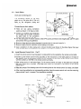
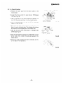
3. HOW TO INSTALL INDOOR UNIT
3-1. Mount the Unit
a) Make an opening on the ceiling and determine the positions
of the suspension bolt holes according to Fig. 6
b) In the holes for the bolts, insert securely bolt anchors (or
bolt holding plugs). Then securely screw the bolts into the
anchors, as shown in the illustration at right. Fig. 7A
— 15—
Exhaust
fan
al
Fig. 3
/ - = —— 7
, TOP —
7 DA
VA LU
6-1/2' min.
Outdoor
unit
<=
_ Valve
Side
Fig. 4
48-7/8" (Ceiling opening)
di.
À |
с 9-5/8" 34-1/4" | 415/16"
15 г = - ul
Sy ИИ ИДИ MAMMA MAMMA
VA
= 7 + i
= | 7 FA И A
8 © / \ Suspension bolts / 7
g2 = A / \ 7
SAA # xl
A /
69 ИИ И ИИ TT
u
a
Fig. 6
bolt anchor
bolt holding plug - Pad insert
(field supply) Rs
dl Li В LL Ld
suspencion
bolt (M10 (field supply)
Fig. 7A
“Тени: |? {бе ceiling pad is not strong enough to suspend
the air conditioner or if it is difficult to use bolt
anchors, secure the suspension bolts with the
construction member. Refer to Fig.7B.
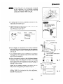
c) If tubing and wire are to go directly out back of unit,
make holes on the wall. Fig. 8
d) Measure thickness of wall from inside edge to outside edge
and cut PVC pipe at a slight angle.
Insert PVC pipe in wall. Fig. 9
PVC pipe INSIDE OUTSIDE
> 3 = (Field Supply)
PVC pipe
Fig. 9
e) Screw flanged nuts (accessories) into the four suspension
bolts, then lift the unit into position so that the suspension
bolts pass through the holes in the suspension lugs on the
unit. Fig. 10
f) Put the special washers onto the suspension bolts upward
which penetrate the suspension lugs and then fasten them
with M10 nuts temporarily.
g) Adjust the suspension height so that the distance between
the bottom face of the flange of the indoor unit and the
bottom face of the ceiling material is approx. 3/4". Fig. 11
Also, suspend the unit horizontally to prevent leakage of
drainage or other trouble.
Ensure that the clearance between the flange of the unit
body and the ceiling opening is as shown in Fig. 12,
Adjust the position of the unit within the range of the
diameter ($20) of the suspension hole. After adjustment,
fasten M10 nuts securely.
— 16—
AD SANYO
(— N
>
—
>
>< i
>> |
<_<
=
=
<
<
N J
~ _ Fig. 7B
PCAUTION
Hole should be made at a
slight downward slant to
the outdoor side.
Indoor Outdoor
| side
Fig. 8
« ay
Suspension bolts (four)
Flanged nuts (accessories)
Suspension lugs
Fig. 10
~~. Special accessory washers {4pcs.)
| M10 nuts (8pcs.)
(+)
| —
a \ E ==
Ceiling Unit flange 3/4”
material
3/8" 9-7/16" 4-11/16"
$
—
?
Fig. 11
NN ANN NANA NN NN
Piping
ное Г Fig. 12
Air conditioner
ИИА,
ИИД ИДИ ИОН
| AN АЛ Л ААА
3/8"
3-2. Wiring Instructions for Interunit Connections
a) Insert the interunit wiring (according to local codes) into
through-the-wall PVC pipe. Run the wiring toward indoor
unit. Fig. 13.
of: \UAE[e]'D) : Never fix the wiring by any means before Connector
. = 1/2" dia.
the indoor unit is fully seated.
Fig. 13
| ЗЫ
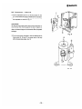
b) Unscrew the cover plate of the electrical component box. 12
Fig. 14 yn |
q |
c) Temporarily set the wiring connector in the hole at the 11 ==
electrical component box. y > N7
QE
===)
d) Secure the conduit connector to the electrical component | Оо
box with a lock nut. Fig. 15 | 4
wd Cover
e) Give some play to the interunit wiring from the outdoor 77 plate
unit to the corresponding terminals on the terminal base. | $ Fig. 14
/ N
Ceiling face
N _/
Fig. 15
CAUTION E
e Be sure to refer the wiring system diagram labelled on the
electrical component box and carry out correct field
wiring. Wrong wiring causes malfunction of the unit.
e Check local electrical codes and also any specific wiring
instructions or limitation.
—17—
3. in Pipi
3-3. Drain Piping ( Drain piping (accessory) в В
Drain pipe connecting parts : N
The connection outlets for the drain E я т :
pipes are on the same side of the unit f E 1
body as the refrigerant piping and 9 ® ey à
0 = :
2 SANYO
electrical box.
Connecting up drain piping
i
Be sure
. . to apply
e There are two piping connection thermal JE
outlets as shown in the figure at right. insulation | “ES
tps
4
—
: y
e Connect up the PVC pipe connectors
and straight pipe provided (indicated « Blind cover |)
by solid lines) to the connection
outlets on the unit body. Fig. 16 Fig. 16
® For the piping past the above accesory pieces (PVC piping connectors and straight pipe), use PVC pipes
and connect them up using adhesive.
e Be sure to slope the drain piping downward, ensuring that no traps are formed in it.
® Be sure to apply thermal insulation to drain piping in the room.
® Upon completion of drain piping work, remove the blind cover shown in the above figure, then pour
water into the drain pan and check to see whether or not it flows satisfactorily.
Install Remote Control Unit: Fig.17
a) Install the remote control mounting plate in a place which can be reached by the remote control cable.
b) Connect up the remote control witing according to the instructions on the label pasted on the back of
the dressing cover of the remote control unit, by matching up the colors of the remote control wiring
with the numbers on the PCB in the remote control unit body.
c) After wiring work as in the below figure, fix the remote control unit body to the plastic box using the
M4 small screws (four) provided. (*The M4 small screws are contained in the packing of the remote
control unit.)
d) Align the prongs of the dressing cover with the mating holes on the remote control unit body, and fasten
them firmly.
e) After mounting pushbuttons on corresponding switches, hang the remote control unit onto the mounting
plate and slide it until it is seated. Thus installation completes.
Mount
on the wall
Remote control-
unit body
M4 Small screw
Dressing cover (4 Pcs.) © Mounting plate
Remote control wiring
Ny Fig. 17
Pushbutton — 18 —
ex: In case of use recessed outlet box,
install remote control unit body,
dressing cover and pushbutton
directly to outlet box as same as
Fig. 17. Do not use plastic box and
mounting plate. Fig. 18
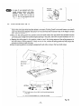
3-5. Install Ceiling Panel: Fig. 19
a) Screw the M5 x 35 small screws provided ( in the ceiling panel packing) into four points on the flange
face of the unit body which has been bolted to the back of ceiling. Screw in the small screws to an extent
such that the distance between the bottom of the screw head and the bottom face of the flange is at least
3/4”. (See figure below.)
b) Next, lift the ceiling panel into position so that the small screws (four pcs) which were screwed onto the
unit body pass through the keyhole-shaped openings in the panel, then shift the panel sideways until it is
caught by the screws.
c) Keeping the ceiling panel in this position, check to see if the joining patterns of the ceiling panes are in
line with those of ceiling material. If they are not in line, remove the ceiling panel and finely adjust the
suspension position of the unit body.
й Recessed
outlet box
) Fig. 18
d) Once the joining patterns are properly aligned with each other, screw-in the four small screws.
EN
Electrical box
M5 x 35 small ;
accessory screws
(four)
( Ai
=— Flange
Ceiling face
=
©
Е
TT
3/4"
Toothed
| lock washer
in the panel.
\_ (2) Then, shift the panel
Screws on the unit 12 4
body (4 pcs)
@ Pass through screws on the unit body into the keyhole-shaped openings
sideways until it is caught by the screws.
—19—
Fig. 19
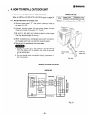
‚ 4.HOW TO INSTALL OUTDOOR UNIT
e Place unit on level pad, blocks or equal and anchor.
2 SANYO
CONNECTOR SIZE
Refer to INSTALLATION SITE LOCATION given in page 14.
MODEL
POWER LINE
CONNECTOR SIZE
INTERUNIT LINE
CONNECTOR SIZE
SAP241C
1/2"
1/2"
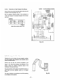
4-1. Wiring Instructions on Outdoor Unit
rr
a) Remove access panel “C” and punch knockout holes on
the panel. Fig. 20
b) Connect interunit power line and power supply line per
drawing on inside of the panel “C”, Fig. 21
c) Be sure to size each wire allowing several inches longer
than the required length for wiring.
d) When connections are completed secure both connectors
on the panel with lock nuts and then close the panel.
e) Ground unit in accordance with local codes.
CAUTION E
® Be sure to comply with local codes on running the wire
from the indoor unit to outdoor unit. (size of wire and
wiring method etc.)
Outdoor unit
Power supply
ccess
e Every wire must be connected firmly. line
e No wire should touch refrigerant tubing, compressor or
any moving part.
y IP Fig. 20
WIRING SYSTEM DIAGRAM
SAP241RC
INDOOR UNIT Interunit OUTDOOR UNIT
TERM Power line
ERMINAL === \ TERMINAL а
070 230/208 | т 2
230/208 V =>
: O | © > ©
+ 230/208 v| | © IS
L___J У а
DISCONNECT @ Da
SWITCH Nl Eg
* FIELD 2 ГИ Её
SUPPLY бо ©
L © eun ne” ZO
Fig. 21
— 20—
Inter unit
power line
5. REFRIGERANT TUBING
5-1.
Use of the Flaring Method
The refrigerant tubing for every split type air conditioner
must be connected by flaring. In this method, the copper
tubes are flared at each end and connected with flare nuts.
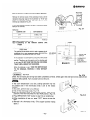
. Flaring Procedure with a Flaring Tool
a) Cut the copper tube to proper length with a tube cutter.
It is recommended to cut approx. 12 ~ 20 in. longer than
the estimated tubing length.
b) Remove burrs at the end of the copper tube with a reamer
or a file. This process is important and should be done
carefully to make a good flare. Fig. 22
LIOR : When reaming, hold the copper tube end down-
ward and be sure that no copper scraps fall into the
tube. Fig. 23
c) Remove the flare nut from the unit and be sure to mount
it on the copper tube.
d) Make a flare at the end of copper tube with a flaring tool*
Fig. 24 (*Use “RIGID” or equivalent.)
Neld-8 : Good flare should have following conditions:
e Inside surface is glossy and smooth.
e Edge is smooth.
e Tapered sides are in uniform length.
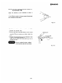
5-3. Caution before Connecting Tubes Tightly
a) Be sure to apply blind cap or water proof tape to prevent
dust or water from getting into the copper tube , until it is
used.
b) Be sure to apply refrigeration oil to the matching surfaces
of flare and union before connecting them together. This is
effective for reducing gas leaks. Fig. 25
c) For proper connection, hold the tube with union and the
flared tube straight with each other, screw in the flare nut
lightly at first to obtain smooth match. Fig. 26
—21—
Deburring
Fig. 22
Copper tube
Reamer
Fig. 23
Flare nut
Copper tube
Fig. 24
Be sure to apply
refrigeration oil
Fig. 25
Union Flare nut
Fig. 26
54.
5-5.
5-6.
Connecting Tubes between Indoor and Outdoor Units
1. Connect the indoor side refrigerant tubing extended from
the wall with the outdoor side tubing tightly.
2. Flare nut on large dia. tube should be torqued to 510 ~ 550
165. in. Flare nut small dia. tube should be torqued to
130 ~ 170 Ibs. in. Fig. 27
3. After performing a leak test on the connecting part,
insulate it with INSUL. NIPPLE and finish with a vinyl
masking tape over it. Fig. 28
CD : Never connect up tubes by brazing them. If
it is inevitable, be sure to blow nitrogen gas
while brazing to avoid oxidation of inside
copper tube.
Insulation of Refrigerant Tubing
Because the capillary tubing is installed in the outdoor unit,
both wide and narrow tubes of this air conditioner become
nl Thana rn + UA PZA ITA + La nat Inns amet те + El aAnra a
LUIU. ПСК, LU prevent Сас оо dIIU WEL T1IVUILD due to
dripping of chilled sweat, both tubes must be well insulated
with proper insulation material. Thickness of insulation
material should be min. 5/16”. Fig. 29
Insulation material
The material must of course have good insulation character-
istics, be easy to use, age resistant, and must not easily absorb
moisture. The following is recommended; foamed polyure-
thane or polypropylene.
Taping the Tubing
a) At this time, the two refrigerant tubes (and electrical wire if
code permits) should be taped together with armoring
tape. The drain pipe may also be included and taped
together as one bundle with the tubing.
b) Wrap the armoring tape from the bottom of the outdoor
unit to the top of the tubing, where it enters the wall. As
you wrap the tubing cover half of each previous tape turn.
Fig. 30
c) Clamp tubing bundle to wall, one clamp every 4’ approx.
[ NOTE E Do not wind the armoring tape around too tightly
since this will impair the heat insulation effect.
Also be sure condensation drain hose splits away
from bundle and empties clear of unit and tubing.
. Finishing the Installation
After finishing insulation and taping over tubing, fill the void
space with putty to prevent rain and draft from entering.
Fig. 31
Torque wrench “
on flare nut
Indoor unit
2 SANYO
Outdoor unit
Fig. 27
DD
— Ey
INSUL
NIPPLE
Fig. 28
Insulation
Min. Thickness:
11617 mame
A \~/ Min. 5/16"
Fig. 29
Apply putty here
Tubing
Insulated
tubes
A - Wall
Fig. 30
Fig. 31
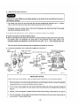
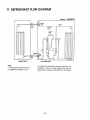
6. AIR PURGING
Air does not function as a refrigerant, because it
cannot be liquefied in the condenser. Air and
moisture remaining in the refrigerant system have
undesirable cffects as indicated at right. Therefore,
they must be purged completely.
B TUBING DIAGRAM FOR AIR PURGING
The pressure in the narrow tube rises.
The operating current rises.
Cooling efficiency drops.
Water contained in the air may freeze and block
the capillary tubing.
e Water may lead to corrosion of parts in the
refrigerant circuit.
(Model: SAP241RC)
= Service .
= = valve Drier
a Narrow ==
tube Capillary
Solenoid
valve ZN
|
| )
|
a le
©
=
Service —
E valve Un || Сотрг.
но (L об с 3] » ,
= S | ЦИ
tae J
Evaporator tube = — IN Ш
(INDOOR UNIT) (OUTDOOR UNIT)
*The solenoid valve is provided to keep the unit
running in cool atmosphere. It opens to bypass
refrigerant flow when the outdoor ambient tem-
prerature drops below 75°F, and closes at 78°F.
6-1. Quick Air Purge System
New quick air purge system represents purg- Men : Outdoor unit is pre-charged at the
ing the air in the indoor unit and connection
tubes with the aid of refrigerant gas pre-
charged in the outdoor unit.
factory. Don't open valves until tubing is
hooked up and you are ready to proceed
with purging procedure.
By this system, air purging has become much
simpler and installation time has become
shorter than conventional methods.
_23—
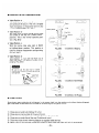
6-2. Air Purging Procedure
a) Remove the valve caps from the service valves on the
narrow tubes.
b) Loosen the flare nut (A) of wide tube by 180 degrees
(1/2 turn). Fig. 32
c) Open the spindle of the narrow tube by 90 degrees (1/4
turn) for 15 seconds and close it to the original position.
d) After 45 seconds, fasten the flare nut (A) of wide tube
tightly as it was. Fig. 33
e) Open the wide tube service valve by a quarter turn and
close it as soon as hissing stops. This indicates that tubings
are filled with the refrigerant gas of the outdoor unit.
1) Leak test the joints with liquid soap. If no leakage, wipe
off the soap. Fig. 34
g) Turn the valve stems all the way out to Back Seat on both
service valves, then, tighten the valve seal caps with the
copper gaskets.
h) The all air purge procedure has been completed and the
unit is ready for trial operation.
— 24 —
Le
2D SANYG
Valve cap
Spindle —
Open by 90 degrees
and close in 15 sec. Fi 32
Loosen =
2
=== > >
A
Fig. 33
Lee
ATA
и &
в O
e
A
Fig. 34
HB SERVICE VALVE CONSTRUCTION
Valve Position -a-
The valve stems of both wide & narrow tubes
are turned all the way in. The unit is shipped
from the factory in this position and it is also
used for PUMP DOWN. (Fig. 35-a)
Valve Position -b-
The valve stems of both wide & narrow tubes
are turned all the way out ("BACK SEAT”
position). This is the normal operating posi-
tion. (Fig. 35-b)
Valve Position -c-
With the narrow tube valve kept at BACK
SEAT, only the wide tube valve stem is turn-
ed halfway-down position. This position is
used for pressure measurement and gas charg-
ing. (Fig. 35-c)
Valve Position -d-
Like position -a-, but with the flare nut of
wide tube open. This position is used for air
purging. (Fig. 35-d)
Be sure to use the valve tool or ratchet
wrench when opening or closing the shut-off
valve spindle, Close
Open \ Valve Tool
E
E PUMP DOWN
Copper gasket 4
Fig. 35-d
Cap
Flare Nut io
-c- Condition at Gas Charging
-d- Condition at Air Purging
Pump down means collecting all refrigerant in the system back into the outdoor unit without losing refrigerant
gas. Pump down is used when unit is moved or for servicing the refrigerant circuit.
1)
2)
3)
4)
5)
6)
Close valve on wide tube halfway (2 turns).
Close valve on narrow tube all the way (4 turns).
Turn unit on (cooling) for approximately 3 minutes then shut off.
Close valve on wide tube all the way (2 additional turns).
Disconnect tubes slowly allowing pressure to equalize inside and out.
When tubing is disconnected provide dust covers for both valves and tubes until unit is reconnected.
—25—
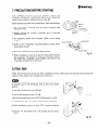
7. PRECAUTIONS BEFORE STARTING
After insulation, be sure to bind up insulation material and
refrigerant tubings with a water-proof tape so as rain should not
creep into the insulation material and wiring. Fig. 36
Before attempting to start the air conditioner, check the following:
a) All loose matter is removed from the cabinet especially steel
fillings and chips.
b) Control wirings are correctly connected and all electrical
connections tight.
c) Ail temporary jumper wires removed. (Refer to unit wiring
diagram.)
d) Check to see if compressor mounting bracket or board, which
secures compressor during transportation, is removed. |f not,
remove them. Fig. 37
e) Be sure to confirm that all shut-off valves are open.
f) Power connected to unit for at least five hours before starting
the compressor. The bottom of compressor should be warm to
the touch and crankcase heater around the feet of the
compressor should be hot to the touch.
8. TRIAL RUN
Nut with washer
2 SANYO
Wide
tube
Narrow
tube
Water-proof
armoring tape
Insulation
material
Fig. 36
Compressor
Remove board
Fig. 37
Check that all tubing and wiring have been completed correctly. Check again that wide and narrow tube service
valves are fully opened. Turn on power and run the unit.
If the room temperature is too low, cooling operation may not
be possible even if the thermostat knob is set at the lowest
position.
In this event, perform test run as follows:
a) Pull off the thermostat knob. Fig. 38
b) Set the thermostat lever to the TEST RUN position. Fig. 39
с} Press OPERATION “ON” button to start the air conditioner.
d) After completion of test run, press “OFF” button to stop the
unit.
e) Reinstall the thermostat knob. (The stopper position facing
down.)
— 26—
Fig. 38
TES
R ы”
DD
Fig. 39
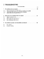
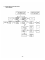
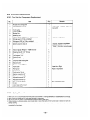
7. TROUBLESHOOTING
— Quick Access Index —
Page
1. Air conditioner does not operate .......... iii ee eee 28
1.1. Circuit breaker trips (or fuse blows)
1.1.1 When circuit breaker is set to ON, it trips soon (resetting is not possible)
1.1.2. Circuit breaker trips when the operation switch is depressed
1.2. Neither indoor unit nor outdoor unit runs
Some part of air conditioner does not operate ....................... 31
Indoor fan does not run
Neither outdoor fan nor compressor runs
Only outdoor fan does not run
Only compressor does not run
2
2
2.
2
2
2 Compressor frequently repeats ON and OFF
о А © №
3. Air conditioner operates, but abnormalities are observed.................. 36
3.1 Poor cooling
3.2 Excessive cooling
— 27 —
| 2D SANYO
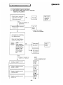
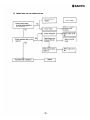
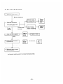
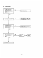
| 1. Air conditioner does not operate
1.1 Circuit breaker trips (or fuse blows)
1.1.1 When circuit breaker is set to ON, it trips soon
(resetting is not possible)
* Check interunit wiring (bet- Refer to wir-
ween indoor and outdoor NO | Execute ing system
units). — | rewiring diagram in
Is the wiring correct? page 20
YES
There is a possibility of
ground fault.
Y
eCheck insulation resistance . Refer to
of power cord ELC-1.
(P.40)
YES
*A defect of insulation
Y of indoor unit is possibie.
eCheck insulation resistance
of outdoor unit. Is the insula-
tion resistance low?
When resistance value is 1
MQ or less, check insulation
resistance of outdoor unit:
STEP 1 Separate interunit
cables.
STEP Check insulation NO N Check insula- Refer to
resistance between = pron of indoor éLcs.
terminal (2) and .
GND and between
terminal (3) and
GND in the elec-
Check insula-
trical component >| tion of indoor
box of outdoor transformer
unit.
YES
A defect of insulation of NOTE:
outdoor unit is possible. In case of insulation defect,
Y replace the respective part.
Refer to
Execute an insulation test for
— ELC-2.
compressor motor.
(P.40)
|_| Execute an insulation test for Refer to
outdoor fan motor. ELC-3.
(P.40)
Refer to
Execute an insulation test for
| crankcase heater ELC-15.
(P.46)
Execute an insulation test for EG. to
— | solenoid coil -12
(P.46)
— 28—
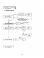
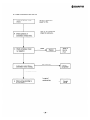
1.1.2 Circuit breaker trips when the operation
switch is depressed.
e Check capacity of circuit
Replace it with a suitable
one. (= larger capacity)
Replace
Replace
Replace
. NO
breaker. 15 capacity of >>
circuit breaker suitable?
YES
NO Check indoor Check outdoor NO
Replace << ls fan motor LS Pam motor Replace
normal? normal ? |
YES y YES
\
Refer to NO | Check indoor Check outdoor | NO Refer to
Replace ELC-5 fan motor fan motor ELC-5
(P.41) condenser condenser (P.41)
| YES
Refer to
Check NO ELC-6
compressor (P. 42)
у YES
Check com- NO Refer to
pressor ELC-5
condenser (P. 41)
Check solenoid Refer to
coil ELC-12
(P.46)
— 29—
2 SANYO
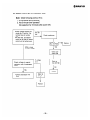
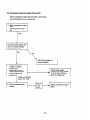
1.2 Neither indoor unit nor outdoor unit runs
Circuit breaker is N
> tripped. > Reset breaker.
eCheck power supply. NO
Is power being supplied to
?
wall receptacle: Wait for recovery or
> Power failure. z| contact power
YES company.
>> Check transformer. »| Refer to ELC-10 (P.
45)
У
. NO Check fuse on the
*Check operation lamp. ls the »| controller PCB for Refer to ELC-8.
YES
Y
When fuse is blown, Refer to ELC-9. (P.
replace it. 44)
Y
* Controller PCB is defective. Replace
—30—
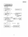
2. Some part of air conditioner
does not operate
2.1 Indoor fan does not run
There is continuity.
Y
e Rewire fan motor correct-
ly and try operation.
— 31
F b Check fan casing летом
an cannot © >! for foreign matter >> > пе
turned. on the inside. a er or
repair.
e Check fan rotation.
Turn the fan gently once
or twice by hand.
Fan motor burn- Repair or
— | out or foreign matter > ге ace
Fan turns in bearing. Р °
smoothly
Y
e Check fan motor capacitor. Refer to >| Repiace in case of
ELC-5. (P.41) defect
y
e Check output of fan motor Refer to | No output check Refer to
terminals on controller ELC-10. »| remo ELC-7.
PCB. (P.46) contro (P.42)
unit
YES
There is output.
y
Control- Replace
> IN Case
ler PCB of defect
y No conti-
nuit
e Check indoor fan motor noe у IN replace
winding for continuity. (P 45) motor
2.2 Neither outdoor fan nor compressor runs
Note: Check following points at first;
1. Is thermostat setting suitable?
2. Has 3 minute timer operated?
(No operation for 3 minutes after
power ON.)
*Check voltage between ter- In саге ©!
minals No. 2 and No. 3 at voit,
terminal base of outdoor voit. | Check transformer
unit..
* (At this time, set selector
switch at left side of remote
control unit to bottom posi-
tion. “TEST RUN”) NO
Refer to
ELC-10 (P.45)
90% or more YES
of rated voltage у
Check con-
troller PCB
À
if voltage Refer t
; e
Check voltage of magnet is O ÉLC.8 P.44)
contactor coil of compressor
motor
NO
4
YES
Replace
*Check compressor wire Refer to
eCheck outdoor fan motor ELC-6
wire (P.42)
Y
Replace
—32—
Replace
2A SANYO
2.3 Only outdoor fan does not run
e Check fan motor circuit.
/
* Be sure to disconnect
power for this.
e Check the fan rotation.
Turn the fan gently once
or twice by hand.
Check fan casing
Remove
foreign
for foreign matter
on the inside.
The fan
turns
smoothly.
Y
The fan cannot
be turned.
—>
Fan motor burn
out or foreign
matter in bearing
e Check fan motor capacitor.
GOOD
/
Refer to
ELC-5.
(P.41)
Y
matter or
repair.
Repairor
replace.
»| Replace if defect.
e Check fan motor winding
for continuity.
Pi
i
Refer to
ELC-4.
(P.41)
No continuity
There is continuity.
and try operation.
e Rewire fan motor correctly
NOTE: The fan motor does not run until the winding temperature lowers
and automatic resetting works if the internal thermostat operates.
—33—
Replace
fan
motor
2 SANYO
2.4 Only compressor does not run
e Check compressor motor * Be sure to disconnect
circuit. power for this.
Y * Wait for 30 minutes and
e Check operation of check for continuity.
compressor overload relay.
A
Defect Refer to
e re r
“heck comer ssor moto y Replace ELC-5.
p (P.41)
e Check for a wire break in No continuity Replace
compressor motor winding. compressor
There is continuity.
y In case of
e Check wiring according to wrong wiring. Correct
wiring diagram. wiring
_34—
2.5 Compressor frequently repeats ON and OFF
(Only compressor repeats ON and OFF, while indoor
unit and outdoor fan run without fail.)
e Check compressor overload
relay.
Has overload relay tripp-
ed?
YES
Y
Is outdoor heat exchanger coil
dirty or are there obstacles
near air suction inlet?
NO
/
® Check power supply
voltage. Is voltage ab-
normally low?
Check voltage between
terminal No.5 and No.6
YES
remove obstacles).
Clean heat exchanger (or
Low (103V or less)
at terminal base in the
outdoor unit.
Voltage is in specified
range (115V +10%).
e Check compressor motor
Consult power supply
company and restore voltage
to normal value. (Remove
cause for voltage drop)
Refer to
ELC-6. —»
winding.
(P.42)
Replace compressor in case of
defect.
—35—
2D SANYO
3. Air conditioner operates, but
abnormalities are observed
3.1 Poor cooling
e Confirm installation posi-
tion ofremote control unit. YES Change installation position of
Does cool air from air remote control unit
conditioner reach position
Y
directly?
NO
. ore wide ond narrow rupes NO Insulate wide tube and narrow
do indoor lat a 3 tube separately and then
outdoor unit insulate execute taping.
separately? |
Note: Throttling capillary tube
YES of this model is located in
outdoor unit.
Y Temperature
e Measure temperatures of difference
suction and discharge air of | Is small. Possibility of gas Charge
air conditioner, and com- f—————> shortage ——»| refrigerant
pare with the characteristics gas (R22).
curve.
Temperature difference between
suction and discharge air is
large enough (Approx. 55 deg. (F) or more)
e Check for clogging of air Air filter is clogged. > Clean
filter. filter.
e Reevaluate cooling load Reduce cooling load or replace
estimate, if performance of — ——»| the unit with higher cooling
air conditioner is normal. capacity.
—36—
3.2 Excessive cooling
e Is TEST RUN selector
switch (at left side) of
remote control unit set to
RUN?
(upper position)
NO
e isset temperature suitable?
YES
Y
e Is remote control unit
installed at a place where it
can detect room tem-
perature properly?
YES
e Does compressor motor
stop when operation push-
button is depressed to
OFF?
YES
—»>| Set switch to RUN,
NO .
> Set temperature to higher value
or set selector lever to AUTO.
NO Ch ,Ç . .
> ange installation position of
remote control unit.
NO Power relay
defect —»1 Replace
YES
Unit is normal.
—37—
ZA SANYO
8. CHECKING AND REPLACING ELECTRICAL
COMPONENTS
— Quick Access Index — Page
ELA. Connector Identification on Controller PCB. . . . . ............ 39
ELC-1. Measurement of Insulation Resistance of the Power Cord ............... 40
ELC-2. Measurement of Insulation Resistance of the Compressor . .............. 40
ELC-3. Measurement of Insulation Resistance of the Fan Motor ................ 40
ELC-4. Checking of the Outdoor Fan Motor 0... 41
ELC-5. Checking of the Motor Capacitor .............. ie... 41
ELC-6. Checking of the Compressor Motor Winding . ........................ 42
ELC-7. Checking of the Remote Control Unit Proper . . . ................ ...... 42
ELC-8. Checking of the Continuity of Fuse on the Controller PCB ............... 44
ELC-9. Method to Replace Fuse on the Controller PCB ....................... 44
ELC-10. Checking of the Power Transformer ............ ... i... 45
ELC-11. Checking of the Indoor Fan Motor. . . . . ........... . . . ... . . ......... 45
ELC-12. Checking of the Solenoid Coil ............. i. 46
ELC-13. Checking of the Coil Thermostat............. 2... me. 1 4 4 4 A . . ..... 46
ELC-14. Checking of the Electric Magnetic Contactor ... . ...................... 46
ELC-15. Checking of the Crankcase Heater. . . . . .............. ..............486
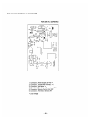
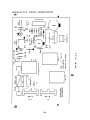
ELA. Connector Identification on Controller PCB
POW-24R (For SAP241RC)
NOION3Y
E
SF
чо
он —+—@ © ET x
x
SIC) | y
© 111 [£ eo (4) _z
a e + E
ox —
ox
5 E © ян с
À E un © d
RIY RIB
R2
m
>
q
R
DEC -T-liav-0
MADE IN JAPAN
E52620
Y 2
FUSE 250V-5A
POW- 24R
4226956362
Fig. E-A
. Connector, Power Supply to PCB *
. Connector, Transformer (Primary: *)
. Connector, Fan Motor *
. Connector, Transformer (Secondary: 19V)
. Connector, Remote Control Unit 24V
. Connector, Thermistor Sensor 24V
©) 1 a wN —
* Line Voltage
—39—
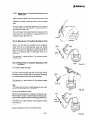
ELC-1. Measurement of Insulation Resistance of the
Power Cord
Clamp the ground (GND) line of the Power Cord with a lead
clip of the insulation resistance tester and measure the
resistance by placing a probe on either of the two power
lines.
Then also meaure the resistance between the GND line and
the other power line. The insulation is in good condition if
the resistance exceeds 1 M2.
Then also measure the resistance between the ground and the
other power line. The insulation is in good condition if the
resistance exceeds 1MS2 (Fig. E-1).
ELC-2. Measurement of Insulation Resistance of the
compressor
Remove the red lead wire connected to the compressor
motor from (4) on the terminal base. Clamp the removed
black lead wire with a lead clip of the insulation resistance
tester and measure the resistance by placing a probe of the
tester to the terminal GND, to which green lead wire is
connected.
The insulation is in good condition if the resistance exceeds
1 M£2(Fig. E-2).
ELC-3. Measurement of Insulation Resistance of the
Fan Motor
3.1. In case of indoor fan motor
Remove the fan motor connector from controller PCB (P39,
Fig. E-A). Clamp the green lead wire (at the bear section)
extended from the terminal GND in the electrical component
box and measure insulation resistance by placing a probe of
the insulation tester to either pole of this connector.
The insulation is in good condition if the resistance exceeds
1 MO. Fig. E-3.
Note:
If the probe does not enter the pole because the hole is too
narrow then use a probe with a thinner pin.
3.2. In case of outdoor fan motor
Disconnect the white lead wire connected to Terminal (6) of the
electric magnetic contactor. Clamp this lead wire with a lead clip
of the insulation resistance tester and measure the resistance by
placing a probe of the tester to the terminal GND.
The insulation is in good condition if the resistance exceeds
1 MQ. Fig. E-4.
3.3. Crankcase heater
Disjoin and check both ends of the crankcase heater
GND
terminal
>
7 SANYO
£
Insulation
tester Fig. E-1
Insulation
tester Fig. E-2
Insulation
tester Fig. E-3
Insulation
tester
Fig. E-4
ELC-4. Checking of the Outdoor Fan Motor
Remove the fan motor lead wires (WHT, BRN, PNK) and check
as shown in the wiring diagram (Fig. E-5).
Set the resistance measuring range of the multimeter to
“X102” and measure the resistance between the fan motor
lead wires.
SAP241C
Lead wire color Coil resistance
WHT — BRN 24 © + 10%
WHT — PNK 54 © + 10%
(Table-1)
Note: When ambient temp is 70°F.
ELC-5. Checking of the Motor Capacitor
Checking of any of the indoor fan motor capacitor, outdoor
fan motor capacitor and compressor motor capacitor can be
done by the same method.
Remove both the lead wire terminals connected to the
capacitor, place the probe on the capacitor terminals as
shown in the Fig. E-6 and observe the deflection of the
pointer, setting the resistance measuring range of the
multimeter to the maximum value.
For good condition of the capacitor the pointer bounces to a
great extent and then gradually returns to its original
position.
The range of deflection and deflection time differ according
to the capacity of the capacitor.
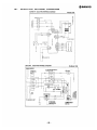
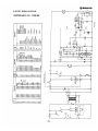
SAP241C ELECTRIC WIRING DIAGRAM
HOLIFLOYdA
aYOTH3AO
HM TYNYILNI
w œ
a o
Эс 3
¥ ww N18 © ©
er ao
< < LHM < E
ST HOLIDVdWD Ss
HOLIOVdYI
E ы - 940
0
= e]
=
2 e
À U w
2 1 E E
к т
9 = М © si o - 5 © © 305
= x O Q w сон
of c PU
22 | -Ле] de] € к z3£
ok O O
ue | | z 5
uo y z & 3 “ou =
— a Ру =
o o <
| d344 14M u
Là о
— H719
- LHMA
<
x Zu \ E
a = a | ©) (о (=) ©) (мч) (- | © 2
3 wd - =
un - a T T —1 DL E o
ec No PUR iii
= 44 111 >
5 ---- 5 | nó о
a----------- J L ©
Fig. E-5
Multimeter
Capacitor
— 41 —
ELC-6. Checking of the Compressor Motor Winding
Remove the terminal cover of the compressor motor, set the
resistance measuring range of the multimeter to ‘‘X1§2"' and
check the continuity between each pair out of the 3
terminals as indicated in Fig. E-7.
It is in good working condition if there is continuity among
each pair of terminals.
— SAP241C
Coil resistance
0.660 + 10%
1.9790 = 10%
Leadwire color
C-R
CS
(Table-2)
Note: When ambient temp is 77°F.
ELC-7. Checking of the Remote Control
Proper
Unit
À. Caution: Use of the Test Switch
(TEST RUN)
The position of the switch which is used to operate the air
conditioner for a room temperature below 69°F (21°C) is
the position of the switch for this TEST RUN. SWITCH
if this operation is continued for a long time, there would
be a bad effect on the air conditioner because of over-
cooling. Therefore, use this switch only for checking, and
in any case, DO NOT KEEP ON COOLING FOR MORE
THAN 15 MIN. UNDER TEST RUN MODE.
When the checking is over, TURN THE SWITCH BACK
TO ITS ORIGINAL POSITION (= RUN) WITHOUT
FAIL.
REFERENCE
Check that all tubing and wiring have been completed correctly
valves are fully opened. Turn on power and run the unit.
CED
If the room temperature is too low, cooling operation may not
be, possible even if the thermostat knob is set at the lowest
position.
In this event, perform test run as follows:
a) Pull off the thermostat knob. Fig. E-8.
b) Set the thermostat lever to the lowest position. (The central
TEST RUN
FAN SPEED
AD SANYO
Multimeter
(X 152 range)
Ja —|
o A + а
№№ ZT LA
q e
Compressor
terminal Fig. E-7
1. REMOTE CONTROL UNIT
INDICATOR LAMP
| | (Green)
|| |
(mm
mon 0
ON
||
N
FAN SPEED OF
OPERATION
TEST
Arm 69 7 13 76 2) 19 81 8385 87 FA
SWITCH
THERMOSTAT
THERMOSTAT
@ SANYG
FAN AND
TEST RUN
SLIDE SWITCH
Fig. E-7A
. Check again that wide and narrow tube service
Ш
ul
||
= ;
1 « {1
et
ро
position of the lever becomes the TEST RUN position.) Fig. E-9.
c) Press OPERATION “ON” button to start the air conditioner.
d) After completion of test run, press “OFF” button to stop the
unit.
e) Reinstall the thermostat knob. (The stopper position facing
down.)
—42—
Fig. E-8
|
T
> |
Fig. E-9
B. Checking of the items of the Remote Control Unit
At first, pull out the connector (7P)
of the remote
control unit from the controller PCB of the unit (refer to
Fig. E-10).
(1) Fan Speed Selector
Check the continuity of the connector No. 3 against
No. 4 (place the negative (—) probe on No. 4 and
positive (+) probe on No. 3.
Checking points
Position of the selector
High Low
3-4 NO YES
(Table-3)
NOTE: YES .................. Continuity
NO .................. Discontinuity
(2) Checking of the Operation Pushbutton
The operating switch is in good working condition if
there is continuity between No. 2 (placing the negative
(—) prove and No. 3 (placing positive (+) probe) while
the pushbutton is pressed.
Fig. E-10
CAUTION:
Do not disassemble the Remote Control Unit.
It is supplied as a complete assembly and is carefully adjusted in the factory by skillful workmanship.
Inexperienced disassembly will cause trouble and malfunction in the unit.
ELC-8. Checking of the Continuity of Fuse on
the Controller PCB
Check the continuity by the multimeter as shown in
Fig. E-11.
If it is difficult to check in this way, remove the lamp board
ass'y connector and then check it.
ELC-9. Method to Replace Fuse on the Controller PCB
i. Remove the controlier PCB
2. Pull out the fuse at the metal clasp by a pair of pliers
while heating the soldered leads on the hack side of the
controller PCB with a soldering iron (30W or 60W). Fig.
E-12.
3. Remove the fuse ends one by one. For replacement, insert
a fuse of the same rating and solder it.
(Allow time to radiate heat during soldering so that the
fuse does not melt).
(07:10 HON ES : Be sure to replace the varistor adjacent
to the fuse either when the fuse is blown.
2 SANYO
Fuse
Fig. E-11
Soldering iron
“a CU NLT
IT 77 Tr Tl 23 2 2 2 2 tL TL Ll Cll ll hcdd dolomite d
[
Fig. E-12
ELC-10. Checking of the Power Transformer
1. Remove connectors TRANS-1 and TRANS-2 from the
controller PCB.
2. Set the resistance measuring range of multimeter to
“X10” and measure the resistance of the lead wires
between WHT-WHT and BRN-BRN as shown in
Fig. E-13.
it will be completely satisfactory if all measured
values agree with those indicated in Table-4.
Lead wires Value of resistance
WHT — WHT About 143.52
BRN — BRN About 1.20
| (Table-4)
NOTE: Ambientroomtemp................... 70°F
ELC-11. Checking of the Indoor Fan Motor
Remove the fan motor connector FM from controller PCB
and measure the resistance between each lead wires of the
fan motor connector setting the resistance measuring range
to “X10”.
The motor is in very good working condition if all the values
agree with those indicated in Table-5.
Lead wires Value of resistance
WHT-BRN About 56 ©
WHT-YEL About 54 Q
WHT-PNK About 75 Q
(Table-5)
Note: Ambient room temp. 68°F
—45—
SAP241R ELECTRIC WIRING DIAGRAM
TERMINAL PLATE
e. MH ——— LK ——
TERMINAL TO
OUTDOOR UNIT
FAN MOTOR
5 |-—GIN
LJ
nm
=
2 Te
®
2Р(А
м
nl
THERMO FUSE
2P(B)
TRANS-2 TRANS1
Pl
TRANSFORMER
CONTROLLER
7F REMOCON
= On | —
on [a [Os]
REMOTE CONTROL
SWITCH
AD SANYO
ELC-12. Checking of the Solenoid Coil
1. From the terminal plate (No. 2, terminal), disconnect RED
lead wire for the Solenoid Coil.
2. From the Coil Thermo (Terminal “H”), disconnect RED
lead wire.
3. Check Solenoid Coil for continuity between the moved
RED lead wires with a multimeter. No continuity means
broken wire. If so, replace the wire.
ELC-13. Checking of the Coil Thermostat
Disconnect the lead wire connected to the coil thermostat.
Check the coil thermostat itself. Satisfactory if the value is as
follows. (Table 6)
ON: 75°F OFF: 79°F
(Table 6)
ELC-14. Checking of the Electric Magnetic
Contactor
Disconnect BLU lead wire from terminal (21) and RED lead wire
from terminal (22) on the contactor and check continuity using a
multimeter. Satisfactory if continuity is assured. If continuity
cannot be verified, the coil must be broken. Check and replace
the coil.
ELC-15. Checking of the Crankcase Heater
Disjoin both ends of the heater and check for continuity.
Satisfactory if continuity is assured. If continuity cannot be
verified, the heater must have broken wire. Check and replace
broken wire.
9. DISASSEMBLY AND SERVICE PROCEDURES
— Quick and Index —
INDOOR UNIT
9-1 Electrical Component Box — Access and Removal ............e.eeees22v0srriorerecenceneo
9-2 Ceiling Panel — Removal ...............eeeesccsrrecicacoorceccoereaecareecoooreeaoa ir eace ce.
9-3 Fanand Fan Motor — Removal .................e..::00000i0i000e e eee AA
9-4 Control Switch Unit — Removal ............eees.eessdd0000rre0rerereceeeeRRR RR RR ReR RR R IZ
OUT DOOR UNIT
9-5 Cabinet — RemOVal eK RER RR RER RR RER RR RER RRR RER RER R RER
9-6 Fan and Fan Motor — RemOoVal ee RER RAR RR RR RR RAR RR RER RR RR RI RRA
9-7 Electrical Component Box — Removal KR eae,
98 Compressor Cover Removal oo er eee
9-9 Compressor — RemOVal ee R RR RRK RER RR RER RAT RER RR ER ER R REKEN
9-10 Compressor Replacement are RR eee KE RAR RK RR EEK RRE RK EE
9-10-1 Tool List for Compressor Replacement
9-10-2 Safety Precautions
9-10-3 Compressor Replacement Procedures
A. Separating the Outdoor Unit
B. Removing the Old Compressor
C. Installing a New Compressor
9-11 Leak Test, Evacuation and Charging ee eee eran
9-11-1 Required Tools and System Set up
9-11-2 System Leak Test at the Service Site
9-11-3 Evacuation
9-11-4 Charging Refrigerant (R22)
— 47 —
@ SANYO
INDOOR UNIT
9-1 Electrical Component Box — Access and Removal
(1) Lift the air intake panel slightly upward and then slide it in
the direction shown by arrow (A).
(2) To remove the air filter, grasp the filter tabs and pull them
downwards (arrow (B). Fig.1
A Fig.1
(3) The electrical component box becomes accessible when
the cover (A) (black color) is removed. Fig.2
WD Fig.2
(4) Remove the cover plates (1) and (2) of the electrical compo-
nent box. Fig.3
Fig.3
(5) The electrical components can be checked in this condi-
tion. с
(6) For removal of the electrical component box, remove the M
four screws shown by the arrows. (A) Fig.4. №
о +
1 I
o Es 2 E ©
TUE AAR
Tr a - SE N (A)
N nu SN
N. ES IN Cs
) e e
[CAUTION]
|
Do not use excessive force for removal of connector sockets
or lead wires.
9-2 Ceiling Panel — Removal
(1) Loosen the four screws (C) (black color).
(@ The ceiling panel screw heads have a special shape as
shown in the figure.
Slide the entire ceiling panel to the side. The ceiling panel
can be removed when the screw heads have moved from
(A) to (B). Fig 5.
[CAUTION]
Support the ceiling panel at the time of removal, so that it will
not drop down.
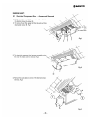
9-3 Fan and Fan Motor — Removal
(1) Remove the cover (A), (B), and (C). Fig. 6
Fig. 6
(A)
2D SANYO
(2) Remove the four screws (A) fixing the fan casing.
(3 When the four nuts (B) fixing the fan motor installation
base are removed, removal is possible as shown in the
figure. Fig. 7.
[CAUTION]
At the time of removal, take care not to drop the fan motor
etc.
Fig.7
(@) Loosen the bolt (A) fixing the fan boss on the motor shaft.
(5) Pull the motor shaft from the fan. Fig.8.
Fig.8
(5) When the four screws (A) around the nozzel circumference
are removed as shown in the figure, the fan can be remov-
ed. Fig.9
(7) When the four screws (A) are removed as shown in the
figure, the fan motor can be removed. Fig. 10.
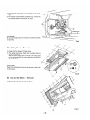
9-4 Control Switch Unit — Removal
(1) Remove the two knobs (1).
(2) When the screwdriver (2) is inserted for about 1/8” into the
notch of the control name plate (3) and raised to the front,
the name plate can be removed.
(3) When the four screws (4) are removed, the cover plate
and the control switch PCB assebly (5) can be separated
from the box.
The control switch unit can be checked in this condition.
(4) For removal of the control switch PCB assembly (5), remov-
ed the connection of the lead wires (6) and remove the four
screws (7). Fig. 12.
—51—
(OUTDOOR UNIT |
9-5 Cabinet-Removal
1 ) Remove the outer panels in the order of front panel (A), side
panel (B), and side panel (C).
2 ) Remove the cover plates (D) and (E).
3 ) Remove the mounting plate (F).
A SANYO
©”
©”
©
9-6 Fan and Fan Motor — Removal
(1) Remove the guard (A) first, and then remove the bolts (a)
of the propeller fan (B) to remove the propeller fan by lifting
it up.
(2) Remove the fan motor wire from the electrical component
box, and remove the top cover (C) with the fan motor fixed
to the top cover. Fig. 14.
—52—
>
x
Y
Fig. 14
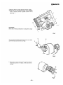
9-7 Electrical Component Box — Removal
(1) Remove the following wires from the electrical component
box.
(1) Compressor wire
(2) Crankcase heater wire
(3) Solenoid valve wire
(1) Remove the cover plate (A) and the fixed sensor (B).
(2) Remove the insulation (C), loosen the fitting fixing the
sensor (D), and remove it.
(3) When the above work has been completed, the elctrical
component box can be removed by removing the screw
(E).
(4) Loosen the screw (H) of the mounting plate (F) fixing the
solenoid valve, and remove the cover (G). Fig. 15
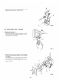
9-8 Compressor Cover — Removal
(1) Remove the four screws (1) fixing the cover (B) and lift the
cover (B) to remove it. Fig. 16
Fig. 16
2 SANYO
9-9 Compressor — Removal
(1) Use an oxyacetylene torch to cut the four places (A), (B),
(C), and (D) where the tubing is welded to the compressor.
(2) Remove the three nuts (E) fixing the compressor, and raise
the compressor to remove it. Fig. 17
[CAUTION]
As there are many places where wires must be removed, ex-
ecute removal after checking against the electric diagram at-
tached on the rear of the cover plate (E) (Fig. 13), and also
refer to this electric diagram for reconnection after compressor
exchange.
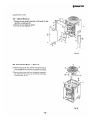
(3) For the new service compressor, tubes are attached at the
three points (A), (B) and (C) to prevent entry of dirt and
moisture. At the time of exchange, connect the unit tubing
after removing these tubes. Fig. 18
9-10. Compressor Replacement
9-10-1. Tool List for Compressor Replacement
No. Item Q'ty Remarks
1 Portable fire extinguisher 1
2 Oxy-acetylene torch set 1 Prest-O-Lite Portable Outfit or
equivalent
3 Torch lighter 1
4 Oxweld goggles 1
5 Brazing flux 1
6 Soldering rod 1
7 Vacuum pump (Capacity: 2 ~ 3 Cu-ft./min.) 1 Robinair or equivalent
8 Nitrogen gas (in 10 Ibs. container) 1
9 Refrigerant R22 (in 10 Ibs. container) 1
10 Refrigerant charging cylinder (5 Ibs. or more) 1
11 System analyzer valve set 1 Robinair, Imperial or equivalent
“Robbi’* thermistor vacuum gauge
or equivalent
12 Vacuum gauge (Range 0 — 1000 microns)
13 Charging hose W/ 1/4" fittings
14 Charge fitting 1/4”
15 Tube adapter 1/4”
16 Pinch-off tool
17 Diagonal cutting plier
18 Long-nose side cutting plier
19 Slip-joint plier
20 Torque wrench (340 165.)
21 Tube cutter
22 Flaring tool
23 Swaging tool
24 Combination file set
25 Regular screwdriver 8”
26 Phillips screwdriver 6°
27 Adjustable wrench 10”
28 Adjustable wrench 12 ”
29 Hex. nut driver (6mm)
30 Oil pan
31 Liquid soap with a brush
32 Clean moist cloth
Imperial or Rigid
Rigid or equivalent
(For compressor bolt)
a m eed ed ed == ed ad em ed ed ed ed ed TJ —
9-10-2. Safety Precautions
1. Make sure unit is disconnected from the power source while it is being assembled or disassembled for servicing.
2. Wear protective goggles at any time when brazing or unbrazing.
3. Be sure to confirm system is at atmospheric pressure before using torch.
4. When brazing or unbrazing tubes, never locate face or any other parts of the human body in direct line with the
tubing opening.
5. Before commensing the trial run, be sure the unit is correctly wired and is grounded adequately when it is
connected to the power.
—55—
AD SANYO
9-10-3. Compressor Replacement Procedures
A. Separating the Outdoor Unit
In case the compressor malfunctions with a split type air conditioner under normal conditions, release the
refrigerant gas at the location first and remove the tubing, then separate the outdoor unit. Pay special attention to
ventilation if the place of installation is small.
1) Make sure that the power is definitely turned OFF and remove the Access Panel “"C” of the outdoor unit
with power line and inter-unit line connectors. Remove wires from terminals within the electrical component
box and wrap the ends of the wires separately with the insulating tape.
2) Place an oil pan at the under side of the service valves. Then remove the caps of the wide tube service valve
and narrow tube service valve with an adjustable wrench. :
3) Leave the wide tube service valve fully close by turning the spindle of the valve clockwise with a valve key or
ratchet wrench. Close the narrow tube service valve in the same manner.
4) Apply two pairs of adjustable wrenches to the union of the wide tube service valve, then disconnect tubing
trom the outdoor unit.
5) Use an adjustable wrench and a torque wrench (130 ~ 170 Ibs. in.), and disconnect narrow tube from the
e ate mm = sa = e
=. а]
UULUVOI UIHL.
The refrigerant gas will seep out from the indoor unit as well as the tubing.
6) Seal the ends of the tubing so that no moisture or dust to enter.
7) Gradually open the narrow tube service valve and release the remaining refrigerant.
8) Open the wide tube service valve and release the remaining refrigerant.
9) Finally leave the wide tube service valve and narrow tube service valve fully open.
10) Clean the oil that has spread around the periphery.
11) Keep the separated outdoor unit in an upright position and carry it to the service station.
B. Removing the Old Compressor
CAUTION E
Always wear welder's goggles when heating the tubing with a torch and make sure not to get too close to the
opening of the tubing. Furthermore, pay special attention to the position of the torch flame so as not to burn
the compressor terminals.
1) The outdoor unit carried into the service shop may have some refrigerant gas remaining within it. Therefore,
make sure that both wide tube service valve and narrow tube service valve are fully open.
2) Remove the cabinet according to the disassembly procedure of the outdoor unit. Refer to Page 52.
Furthermore remove the terminal cover at the top of the compressor and remove the wiring of the overload
relay and the compressor terminal. Fig. 20.
3) Set aside an Oxy-Acetylene torch which is needed for removing the tubing of the compressor.
4) Confirm that system has reached atmospheric pressure.
5) With an Oxy-Acetlyine torch apply heat uniformly and unbraze the joints of upper section of the Liquid Injec-
tion Capillary tube to the compressor, the upper section of the accumulator and the upper section of the
compressor discharge tube respectively, and pull them free with pliers. Fig. 19 shows unbrazing points with
arrows.
* Be sure to save all mounting components with the replacement compressor for future use.
6) To remove the compressor, raise it straight and disengage from the base unit.
TUBE у
"DISCH (3/8 7+
TUBE SUCT (5/8'') | Mounting Component |
TUBE | Terminal Components |
BYPASS(5/16"") NUT SPECIAL
/ Nut 2 ASS Y
over
TUBE LIQUID an OVE 1 COMP.
INES TION DE Gasket BASE
/4”) aske
= OU terminal
Weld boit CUSHIO |
LIQUID Terminal Compressor
INJECTION“ top
CAPILLARY SPRI
UNIT BASE
Discharge
tube SCREW SPECIAL
Fig. 19 Fig. 20 Fig. 21
IMPORTANT NOTICE
Before installing the new compressor, check for possible system contamination by the following procedure:
e Place about 10 cc of the oil from the old compressor into a transparent container and visually check the degree
of oil contamination. If the oil has a slight burnt odor but no color change or residue, and ordinary compressor
replacement accoring to the instructions below may be carried out.
e If the oil has a burnt pungent odor and shows contamination (dark color with tiny particles of metal) the
system must be cleaned sufficiently with a suction filter or a drier-strainer and then replace the oil drier with a
new one.
e However, if just the compressor is replaced without sufficient system cleaning, contaminated oil may cause the
buring of the compressor again.
e If the oil compressor is to be scrapped, by pinching the terminal section with a pair of pliers, there should not
be any chance of it being mistakenly used.
— 57—
2D SANYO
C. Installing a New Compressor
1. Make sure that the defective old compressor has been removed and the new compressor to be installed is of the
same specification by checking the 8 digit code number on stamped marking on the upper section of the
compressor helmet case. (e.g. : 80648646 ) For the detail of the compressor identification refer to page. 4.
2. Transfer the mounting parts to the new compressor.
3. Nick the end of the pinched suction tube of the new compressor with a pincher and release the holding charge
(Nitrogen: 29 psig).
4. With an Oxy-acetylene torch and pliers, unbraze compressor seals at both discharge port and suction port (upper
part of the accumlator).
CAUTION LE
Be careful of the position of the torch so as not to burn the terminals of the compressor when brazing or
unbrazing.
5. Install the new compressor in exactly the same manner as the original compressor.
(* See CAUTION bottom of this page.)
6. Shape both the suction and discharge lines to the approx. area of the compressor fittings and engage each tube
end to the mating compressor fitting.
7. Hold tubing securely with pliers and braze all connections carefully with the torch.
8. Perform leak test, evacuation, and charging refrigerant according to procedures described in section 9-11. page. 59
(0752 (0) E * If the old compressor was heavily contaminated, be sure to replace strainer (or drier) when replac-
ing the new compressor.
9-11. Leak Test, Evacuation and Charging
9-11-1. Required tools and system set up
No. Item Q'ty
1) Vacuum pump 1
2) Vacuum gauge 1
3) System analyzer valve set 1
4) Charging hose (With 1/4’ connector) 6
5) 1/4’ Flared tube cross fitting 1
6) Charging Cylinder 1
7) 1/4" Flared Packless valve 3
(To be used for V3, V4 and V5)
9-11-2. System Leak Test at the Service Site
After replacement of the new compressor, the system must be
checked for leaks according to the below mentioned proce-
dure:
* If cylinder has not yet been filled, move at least one pound
of refrigerant {R22) to the charging cylinder. Fig. 22.
1) Prepare the system analyzer valve set and connect charging
hoses as in Fig. 23. Be sure to close all valves before
connection. (Refer to page 25, Fig. 35-C)
Confirm that both Narrow Tube and Wide Tube service valves
on the outdoor unit and are fully opened, and
other valves are still closed. (Refer to Fig. 24)
Open valves (JB) . and respectively to allow
refrigerant gas entering into the system. Charge about 1/2
pound of gas to the system and close В), and
in sequence.
2
——_
3
——
Apply liquid soap at charge hose connectors, discharge and
suction tubes, and brazed liquid injection capillary section
of the replaced compressor or other connection parts, and
check to see change of bubbles. An electronic halogen gas
leak detector, of course, may be used for this porpose.
4
Sr
5) When leaks are located, depressurize system and repair
leaks.
6) if there are no leaks, open QUE), purge the 1/2 pound of
refrigerant from the system and proceed for evacuation in sec-
tion 9-11-3. Refer to page 60.
* Refer to page 25 in regard to the operation method for the
serveice valve
x
procedure for
One of conventional system set up and
leak test, evacuation and
charging is described in section 9-11 for the
reference.
** Robinair
or
Imperial Portable Charging
Station may be used as a convenient
packaged tool for the purpose of servising
the refrigerant system.
x 7
Gasket 7
Charge fitting
To be connected
to the
Wide Tube
service
valve (Outdoor Unit)
va
R22
_59—
v4
System analyzer valve set
7 O * V1 must
be closed.
V2 G (Hi) | v1
‘м
Tube cross fitting
JOO
Ne Vacuum
gauge
Vacuum pump
Fig. 23
9-11-3. Evacuation
1) Connect instrument as in Fig. 24.
2) Confirm that all connections are made correctly and check
all valves are closed. * and should be fully open-
ed. (Refer to page 25, Fig. 35—C)
3) Open QP) only.
4) Open and CD. Never fail to open the shut off valve
on the vacuum pump if there is.
5) Run the vacuum pump for evacuation. Required time for
complete evacuation differs with capacity of the pump.
(Consult shop manual for specifications)
2D SANYO
x
V6 Service
— < - valve
Narrow jr <<
tube
4 way valve
* While system is evacuating, utilize this time to fill the
charging cylinder, if it is not ready.
if vacuum gauge reading has reached 500 microns or less,
stop the vacuum pump and close
Ss
7
——
Keep this condition at least 5 minutes and observe the
vacuum gauge for change. (Fig. 25)
If pointer on the gauge moves to larger numbers, check
system for leaks again according to the procedure in section
9-11-2. Page 59.
If the indication of the vacuum gauge will not change,
system is now prepared for charging refrigerant. Close QD
8
——
9
—
Proceed to charging refrigerant in section 9-11-4. Page 61.
NOTE:
This model uses low pressure on the narrow tube side as well
as on the wide tube side. Accordingly, the piping on both
sides must be insulated at the time of installation.
Service v7 5
valve =
Heat == I
exchanger | Wide
(INDOOR UNIT) (OUTDOOR UNIT)
System analyzer valve set
Compound / Pressure
Gauge Gauge
/ v2 6 (4) MY must
\ 7 ¥ be closed.
Tube cross fitting
v8 va # Vs
——
JOO
V3 Vacuum
gauge
Vacuum pump
Fig.24
If pointer moves this
Target direction, leackage
value a May be possible.
2
02 : 5
; TERS OF wm
we wt ERC La,
\
\ 1000 MICRONS
oJ Na
\ ‘500 MICRONS
N “300 MICRONS
100 MICRONS
Fig.25
9-11-4. Charging refrigerant (R22)
a
b
1
2
3
“чо”
Sapp
“ча”
—
—
4)
5
—
6)
7
8
9
—
—
—
Preparation of Refrigerant
Measure the net weight of the charging cylinder before
charging refrigerant and memorize it.
Refill required amount of refrigerant from the container to
the charging cylinder. Be sure to measure the cylinder
contents by weighing it. Fig. 26.
NONE: Do not confuse the refrigerant gas level
graduations on the charging cylinder with the
weight. Vapor refrigerant on the upper
cylinder part must be taken into considera-
tion.
Charging Procedure
Evacuate system according to the procedure in section
9-11-3
Confirm that valves ED. , CD. , V5} and
are closed when evaculation is completed.
Open charging cylinder valve CZ) slightly.
Loosen hose connection at a little to let air escape
from the hose. Then tighten connection again.
Measure and memories charging cylinder weight to charge ex-
act amount of refrigerant.
Open V4) fully to supply refrigerant gas to CA.
Close 72 halfway (2 turns) for charging refrigerant. (Refer
to page 25, fig. 35-b.)
Open €P gradualty and let refrigerant gas entering into the
system.
When full charge has entered system (do not permit liquid
level to drop blow “0” (zero) on the graduation of the
charging cylinder), close YF) tightly.
10)0pen QED fully until it reaches to the back-seat position.
(Refer to page 25, Fig. 35-b)
11)Close ID and ED .
12)Loosen hose connections and let refrigerant escape from
hoses.
13)Remove hoses, charging cylinder and system analyzer valve
set. Now, system charging has completed.
—61—
cylinder
0.5lbs. plus specified amount
given on the name plate of
each unit.
See specifications on page. 1.
Fig. 26
MEMO
SAP241R
10. PARTS LIST INDOOR UNIT
Ш Accessory Parts List
LIST OF PACKAGED PARTS
Description Shape Q'ty Remarks Description Shape Q'ty Remarks
PVC elbow 1 854-2-2334-12300| Flanged hex nut E 4 |854-0-1355-10201
PVC T-fitting Sá 1 | 854-2-2334-12200. Special washer ©) 4 |854-2-1355-13101
PVC pipe a 4 | 854-2-2334-12400 =
Remote control Фо 1 859-2.1463
unit ===
PVC socket OL 2 |854-2-2334-12100 ==
Pan-hed screw 4 3-9231-54003
5x40mm Read wire
for
Countersunk-head
(Drau - . 1 ¡851-0-5292-14600
wood screw 31 «13mm 2 3 9261 21 301 emote control
Drain Hose
adaptor (0 1 | 854-2-2334-13600
ATTENTION !
To ensure correct parts supply, please let us know followings, when you
2 SANYO
SAP241R
INDOOR UNIT
make service parts order:
1. Part No. 2. Description 3. Q'ty 4. Volts - Hz - Ph 5. PRODUCT MODEL NO.
Re Part No. Description Q'ty Roy Part No. Description Q'ty
о. о.
1 | 859-3-4123 Panel Ass'y 1 61; 854-2-5301-44711 Bottom Plate 1
2| 854-2-1114-10713 | Cover, Top Panel 2 62 | 851-0-5158-08000 | Control Switch PCB Ass y 1
3 | 854-0-1105-224H2 | Top Panel Ass'y 1 63 | 854-0-5302-14201 Mounting Plate Ass'y 1
4 | 854-0-1105-216H4 | Top Panel Ass'y 1 64 | 854-2-5304-28100 | Cover Plate 1
5 | 854-6-4729-71600 | Label 1 65 | 800-2-5367-11300 | Filter 1
6) 854-2-1521-11300 | Mounting Rubber, Blade 2 66 | 854-2-1359-21 701 Indicator Plate 1
7| 854-0-1505-178H2 | Blade Louver Ass'y 2 67 | 854-2-1311-12401 Knob 1
8 | 854-2-1521-11400 | Mounting Rubber, Blade 2 68 | 854-2-1311-10904 | Knob 2
9 | 854-0-2308-23700 | Air Filter Ass’y 1 69 | 854-2-1311-12002 | Knob 1
10 | 854-2-1133-193H2 | Cover Plate Ass'y 1 70 | 800-2-5367-11600 | Filter 1
11 | 854-2-1133-194H2 | Cover Plate Ass'y 1 71 | 851-2-5261-24100 | Label 1
12| 854-0-1105-230H3 | Top Panel Ass'y 1 72 | 851-2-5261 -26600 Label
13 | 854-2-1301-25001 | Ornamental Sash 1 E | 85464119-38200 | Opetation Manual
14 | 852-2-1504-16414 | Badge 1 H | 854-6-4139-34200 | installation Instructions 1
15 | 854-2-2307-11901 Cover Plate 1
16 | 851-0-5290-687M1 | Fan Motor Ass'y KFG45-81 B6P 1 NOTE: Metal and plastic parts will be supplied basically
17 | 854-2-2534-13510 | Cushion Rubber 2 with necessary heat insulating pads or packing.
18 | 854-2-2519-11400 | Air Guide 1 Some key numbers are intentionally omitted or
19 | 854-2-1367-35300 | Name Plate 1 ieft biank for the editor's convenience.
20 | 854-0-2502-1 7801 Blower Casing Ass’y 1
21 | 854-0-2501-14800 | Blower Ass'y 1
22 | 854-0-2511-15401 Support Motor Ass'y 1
23 | 854-2-2360-41 501 Mounting Plate 1
24 | 854-0-2516-12401 Partition Plate Ass'y 1
25 | 854-2-2518-28700 | Mounting Plate 1
26 | 854-2-2307-12401 Cover Plate 1
27 | 854-2-2352-12300 | Guide 2
28 | 854-2-1133-181H3 | Cover Plate Ass'y 1
29 | 854-2-1101-450H2 | Front Panel Ass'y 1
30 | 852-2-2396-10103 | Screw Special 1
31 | 854-0-5301-335H1 | Electrical Component Box Ass'y 1
32 | 852-6-4729-17300 | Label 1
33 4-2239-56220 | Fixed Capacitor 440V 3MFD 1
34 | 851 -0-5250-687P1 Transformer Ass'y ATR-J122U 1
35 | 854-2-5304-26601 Cover Plate 1
36 | 854-2-5301-49401 Mounting Plate 1
37 | 854-2-5304-265H1 | Cover Plate Ass'y 1
38 | 854-2-1358-46700 | Label 1
39 | 854-2-5301 49501 Mounting Plate 1
40 | 851-2-5250-83800 | Wiring Diagram 1
41 | 8594-7411 Controller POW-24R 1
42 4-2379-56168 | Terminal Base 3P 20A 1
43 : 854-0-5301-33701 Electrical Component Box Ass'y 1
44 | 851-0-5290-687T1 | Thermistor Ass'y OCS5K-UL 1
45 | 854-0-1105-191H3 | Top Panel Ass'y 1
46 | 854-2-2314-184H2 | Partition Plate Ass'y 1
47 | 854-2-1130-12200 | Mounting Plate 4
48 | 854-0-1102-196H2 | Side Panel Ass'y 2
49 | 854-2-1110-14001 Blade Louver 2
50 | 854-0-1306-177H2 | Mounting Plate Ass'y 1
51 | 854-2-1102-275H2 | Side Panel Ass'y 1
52 | 854-2-2314-183H2 | Partition Plate Ass'y 1
53 | 854-04118-35001 Evaporator Ass'y 1
54 | 854-0-2301-300H0 | Drain Pan Ass'y 1
55 | 854-0-2301-302H2 | Drain Pan Ass'y 1
56 | 854-2-4134-31601 Cover Plate, Evaporator 1
57 | 854-0-2301-301H0 | Drain Pan Ass'y 1
58 | 854-2-4134-31501 Cover Plate, Evaporator 1
59 | 854-0-2301-303H2 | Drain Pan Ass'y 1
60 | 859-2-1463 Remote Control Switch Ass'y 1
RCS-24R
SAP241C
OUTDOOR UNIT
10. PARTS LIST
88
"
L
Compressor Ass'y extracted
— 65—
@ SANYG
SAP241C
OUTDOOR UNIT
ATTENTION |
To ensure correct parts supply, please let us know followings, when you make service parts order:
1. Part No. 2. Description 3. Q'ty 4, Volts - Hz - Ph 5. PRODUCT MODEL NO.
Rev Part No. Description Q'ty id Part No. Description Q'ty
1] 854-0-1113-13801 | Guard Ass'y 1 59 | 852-0-4506-14000 | Strainer Ass'y 1
2 | 854-0-1106-20201 | Top Cover Ass'y 1 60 | 854-24219-58100 | Capillary Tube 1
2 | 854.2.2346-11400 | Cap 1 61 | 852-2-2353-19500 | Packing 1
4 | 854-0-2501-18100 | Propeller Fan Ass'y 1 62 | 852-2-2309-34101 | Mounting Plate 1
5 | 854-2-2529-10101 Bolt Special, Propeller Fan 1 63 3-9030-00508 | Clamper F6 2
6 | 852-2-2514-10700 | Cap Rubber 1 64 | 853-2-4310-10300 | Packing 1
7 | 851-0-5290-636M1 | Fan Motor Ass‘y KFC8-101A6P| 1 65 | 851-0-5290-636H1 | Heater Ass'y CH5700 230V 30W! 1
8 | 854-0-2511-14400 | Support Motor Ass'y 3 66 | 851-2-2356-16901 | Mounting Plate, Accumulator 1
9 | 854-2-2360-18900 | Mounting Plate 2 67 | 801-2-5303-13100 | Gasket Terminal 1
10 | 854-2-4134-32100 | Mounting Plate 1 68 | 801-2-6194-12100 | Cover Terminal 1
11 | 254-0-2206-18100 | Frame Ass'y 2 69 | 801-2-8305-10100 | Nut 5mm 1
12 | 854-0-4106-18500 | Condenser Ass'y 1 70 | 854-2-5301-48401 | Electrical Component Box 1
13 | 854-2-1113-12400 | Guard 1 71 3-9030-00508 | Clamper F-6 1
14 | 854-2-2360-19100 | Mounting Plate 2 72 4-2379-56175 | Terminal Base 6P 30A 1
15| 854-2-1353-11000 | Cushion Rubber 4 73 | 852-2-2396-10103 | Screw Special 1
16 | 854-0-2204-35801 | Bottom Plate Ass'y 1 74 3-9030-00512 | Clamper F-10 1
17 | 854-0-1102-234H0 | Side Panel Ass'y, Right 1 75! 854-2-5304-26100 | Cover Plate 1
18 | 854-2-1133-20101 | Cover Plate 1 76 | 854-2-1358-46700 | Label 1
19} 854.2.1133-17501 Cover Plate 1 77 | 854-2-5304-26000 | Cover Plate 1
20 | 854-24310-10100 | Mounting Rubber, Capillary 1 78 | 851-2-5250-76800 | Wiring Diagram 1
21 3-9030-00506 | Clamper F-4 2 79 4-2339-56195 | Thermostat YTB-4U201 1
22 | 854-2-2360-26801 | Mounting Plate 1 80 4-2329-56284 | Relay CLK-16E3-21 1
23 | 854-0-1101-301H0 | Front Panel Ass'y 1 81 4-2239-56224 | Fixed Capacitor 1
24 | 852-2-1320-10500 | Eyelet Rubber 1 440VAC 5MFD
25 | 854-2-1367-31500 | Name Plate 1 82 4-2239-56339 | Fixed Capacitor 1
26 | 854-6-4729-68600 | Label 1 400VAC 35MFD
27 | 854-8-4729-71600 | Label 1 83 | 852-2-5301-20600 | Clip. Capacitor 1
28 | 854-2-1354-14300 | Badge 1 84 | 854-0-5301-33001 | Electrical Component Box 1
29 | 854-0-1102-233H0 | Side Panel Ass'y, Left 1 Ass'y
30 | 854-0-4514-10200 | Charge Port Ass'y 1 85 | 852-6-4729-17300 | Label 1
31 3-9030-00512 | Clamper F-10 1 86 | 854-0-2325-16900 | Cover Ass'y 1
32| 854-0-4521-11100 | Valve Ass'y 1/4" 1 87 | 854-2-2208-195H0 | Mounting Plate Ass'y 1
33 | 854-0-4506-16200 | Valve Ass'y 5/8” 1 88 | 852-0-4516-15700 | Compressor Ass'y C-RI90HEN | 1
34 | 852-2-2356-13301 | Mounting Plate, Tube 1 (806-4-8646)
35 | 854-2-2336-48200 Packing 2 . . .
36 | 852-2-2356-13201 | Mounting Plate, Tube y | NOTE: with necessary hast insulating Tue or packing,
37 | 854-24315-13900 | Packing 1 ! 9-
38 | 854-2-4316-12100 | Mounting Plate, Tube 1 Some key numbers are Intentionally omitted or
39 | 854-2.2336-49200 | Packing 1 left blank for the editor's convenience.
40 | 854-2-4316-12200 | Mounting Plate, Tube 1
41 | 852-04505-13600 | Dehydrater Ass'y 1
42 | 853-2-2340-21 901 Mounting Plate, Tube 1
43 | 854-2-4134-16501 Mounting Plate, Tube 1
44 | 854-2-2360-28700 | Mounting Plate 1
45 | 854-2-4315-13500 | Packing 1
46 | 853-2-4319-11200 | Packing 1
47 | 854-24549-10100 | Solenoid Valve NEV603DXFU | 1
48 | 851-0-5290-636C1 | Solenoid Ass’'y NEVAC208V 1
49 | 854-2-2360-38000 | Mounting Plate 1
50 | 854-2-4316-13101 Mounting Plate, Tube 1
51 | 854-0-4517-17800 |¡ Accumulator Ass'y 1
52 | 851-2-2390-14000 | Cushion Rubber 3
53 | 851-2-2330-13201 | Spring 3
54 | 854-2-2356-10500 | Rubber Protection 3
55 | 854-2-2356-10600 Rubber Protection 3
56 | 854-2-2349-12201 Spacer 3
57 | 854-2-2356-10400 | Rubber Protection 2
57 | 854-2-2356-10700 | Rubber Protection 1
58 | 854-0-2321-10201 Nut Special Ass'y 2
58! 851-0-2395-10702 | Nut Special Ass'y 1
CAP TUBE ASSY 854-0-205-30300
11. REFRIGERANT FLOW DIAGRAM
(Model: SAP241RC)
fe
5)
tube ; 7)
Capillary a
(4)
Solenoid
valve IN
(8)
7) 2)
Service
| valve
кк. fam!
=
(6) Wide
Evaporator tube Cond
ondenser
(INDOOR UNIT) (OUTDOOR UNIT)
NOTE: The solenoid valve is provided to keep the unit running in cool
with sequential number shows flow atmosphere. It opens to by-pass refrigerant flow when the
of regrigerant in COOLING CYCLE. outdoor ambient temperature drops below 75°F, and closes at
78°F.
—67—
12.
ELECTRIC WIRING DIAGRAM
SAP241R ELECTRIC WIRING DIAGRAM Indoor Unit
TERMINAL PLATE >
oz ----- BLK >
23 — wi
IE WHT F
Zo 2207 QP-O
sn
5... RED =
+ © | = E
=
no (©) 1]2]3] —
(11213) - aa
tu SH 1
GRY mon Ne 212 so gy
YEL 2/21 |
WHT 3/3/09 N
— on 1}—BRN
= ©
| == BAN
e E TRANSFORMER
=
o
© CAPACITOR x |
E > 1/1] BRN 5
= РУК o kl RED с
z BRN 31343 ORG 5
2 — lil 1 с |5 5| PNK - 8
Е ik Sfofs— во SE
| 7|7)+——BLK u à
G Y Y
а ©
THERMISTOR
SAP 241C ELECTRIC WIRING DIAGRAM Outdoor Unit
POWER SUPPLY
" CONTACIONENET chan
11 | TERMINAL HEATER
111 PLATE BLK QO UY
рр РАЯ a 3 4 WHT
a | 2
a 1 ——
|1 =--{ 6 BRN ——=0|0O- RED
Do — BRN | 5 oP 6 т
L Ld
| ZZ
f BLU
Ea O) Ex | | я 5
| > m x o
r--94(3 + J LL BLU
| | SOLENOID COIL
— 2
Df Г | r—SC)—ne0 Do Tl x
oy Eo нс Elo
| + 1} = w E E Y
| ; | — о COIL THERMO q O E à
| |! La —— a| <I
poo a BAN % a 3 о ©
1 1L© of § 2
Nada FAN MOTOR z9©
| Eee
eh PNK myo
lo | BRN 255
TO INDOOR UNIT x
? INTERNAL
| OVERLOAD COMPRESSOR
G PROTECTOR MOTOR
2D SANYO
(PRINTED PATTERN)
CONTROLLER P.C.B. POW-24R
à vec- MOd
©
NOION3%3
~
HL
de
¿2-SNYayL
©
+
A EY
—N— 9y
—— 18 zi 99
—
Ely €9 À Ola
N YI 4
q 2 | Liu
» ||
LI ot
sI — м |
RE
|
NVdVr NI 3AQVIN
029293
O -A?PyI - 1 - 930
l'A
913
c A ы
A
ЕО
81d ely
A
N+
I-SNVYL
©
a
1141
тт
8) 692 огы ? yl
Co
— «|
|
29€9s692¢2y
YY —-MO0d
11
3P—A
VS-A0SZ 13SNA
2
Ш
SUP
— 69 —
2 SANYO
qvZ-MOd
Zozy | =
> 59
yi 69 89 | + @
18$ vo oOLH
$618 1 T
1 alu 0 ou
5 ANA Pt AAA L - € 6 Î
a ga т SNVEL _ SNVEL
JET NT Lo y
C/TOIE == и”
4 99, Xx (NYD)
- + My NW Zz/191 = 7 } an
970 ey > El 117
и Le
MA LAY |
cle
us +
< Z
БАН OLI
tu
Es NOJOW3Y мел HOIH
zon hid © MoT
IMS
$
MINS
9
Lo
i i
LMS
! dé |
bee ee 0 J
HbZ-SIE NOJOW3Y
de Bnid 3 40 3 9ESOSZ JO)SISUEL | HL UCL My/l 10)s1sey y
oc L-GZ8LLL 10108Uu0) dí XxXZzY7SG эро! £G OZ Z Mb/l 1015188 y Осн
<} dc bnid Xzv7-Sa spolg ca 089 Mb/L 1034598 6.4
N VEO-£EZZG J0}5euu0o9 dé XZtb-SQ epoig La O “EY My/I 1025158 y 8.H
> < (d3Y) de Bnid 1eL-YZ9 эро az UHOL Mt/l 1203458 ZI
< O £-6292.1-8 40198UU09 (9)d£ JOL-Yga 8polg as U>0£E Mb/l 101858 9.4
© a (NT8) de Bnid 4104p AOS зомоеае:) 019 VWIEE My/L 2015159 su
Oo £-6292L1-C J0Payuog (V)dE 47220°0 AOS Joledeg 62 UAXOL Mtb/l 101959 vid
< A dz Bnig z- 372200 AOS iouveden 89 ILL Mb/L ossay | eu
© . C69%EZLL 10198UU0 | SNVHL 412200 AQS Jolede) ZI U*0/t Mb/l 40)5IS9H Cid
m © (X18) dz bnid L- 370€£ AOL soyoedeg 99 U%OL My/I 3038598 Lid
> O. Z-6Z9ZZ1-Z 101299905) | SNVYL d7Z't AOL зомоювае:) GI %1F UXE Mv/l 10)S1S3} (0185
oc oc HOZHY-YNS JOSE A A (Z) 4"ZZ0'O0O AoS Joiede) vO %LF BYE My/I 103959 64
= Ш AYCIO 3H97-971 Aejay SAH (2) 472200 AOS злоуюеае:) £0 75099 MP/L 101S8S9 y 8H
= AvZOO 3HP7-971 Aejay ZAY (2) 42200 AOS зомовае:) zo %1+ UIBL Mb/L Jolsisay 94
O O AvZIC 3HP7-971 Aejay LAY (2) 42200 AOS JOHSEdeg LO UV‘ E МЛ! 101sISa y сн
сс сс agsyov V4 AOGZ asn4 101958UL07 3 UDOL M2/l JO)sisay ¿y
т 5 10 G8SStWKN al Ol VC E Mt/l 101S1S8 y ECH 3099 MI 101sisay IH
"ON 'O "O
8 UOdLIS8C Ав) uondimsag лем uondieg доз
—70—
13. APPENDIX (Conversion Tables)
Centigrade «=> Fahrenheit
Numbers in the center column (between those marked C and F) refer to temperature, Centigrade or Fahrenheit, which it is
desired to convert into the other scale. To convert from Fahrenheit to Centigrade find equivalent temperature in left hand column
%. °F °c. °F. °c. OF. °c OF °c OF °c °F
—40.0 —40 —42.0 — 6.7 20 63.0 15.6 60 140.0 37.8 100 212.0 82.2 150 336.0 137.8 280 536.0
—38.9 —38 —35.4 — 6.1 21 69.8 16.1 61 141.8 38.9 102 215.6 83.3 182 359.6 140.6 235 545.0
—37.8 —36 --32.8 — 5.6 22 71.6 16.7 62 143.6 40.0 104 219.2 84.4 184 363.2 143.3 230 554.0
—36.7 —34 —292 | — 5.0 23 73.4 17.2 63 145.4 41.1 106 222.8 85.6 186 366.8 146.1 295 563.0
—35.6 --32 -—25.6 — 4.4 24 75.2 17.8 64 147.2 42.2 108 226.4 86.7 188 370.4 148.9 300 572.0
—344 -—30 —22.0 | — 3.9 25 77.0 18.3 65 149.0 43.3 110 230.0 87.8 190 374.0 151.7 305 581.0
—33.3 -—28 —184 | — 3.3 26 78.8 18.9 66 150.8 44.4 112 2336 88.9 192 377.6 | 154.4 310 590.0
—32.2 -—26 —148 | — 2.8 27 80.6 19.4 67 152.6 45.6 114 237.2 90.0 194 381.2 157.2 315 599.0
—31.1 —24 —11.2 | — 22 28 82.4 20.0 68 154.4 46.7 116 240.8 91.1 196 384.8 160.0 320 608.0
—300 —ZZ — 1.6 | — 1.7 29 84.2 20.6 69 156.2 47.5 118 244.4 92.2 198 388.4 162.8 325 617.0
—28.9 —20 — 4.0 — 1.1 30 86.0 21.1 70 158.0 48.9 120 248.0 93.3 200 392.0 165.6 330 626.0
—27.8 —18 — 0.4 — 0.6 3 87.8 21.7 71 159.8 50.0 122 251.6 94.4 202 395.6 168.3 335 635.0
—26.7 --16 3.2 0.0 32 89.6 22.2 72 161.6 51.1 124 255.2 95.6 204 399.2 171.1 340 644.0
—25.6 —14 6.8 + 0.6 33 91.4 22.8 73 163.4 52.2 126 258.8 96.7 206 402.8 173.9 345 653.0
—24.4 412 10.4 1.1 34 93.2 23.3 74 165.2 53.3 128 262.4 97.8 208 406.4 176.7 350 662.0
—23.3 —10 140 1.7 as 95.0 23.9 75 167.0 54.4 130 266.0 98.9 210 410.0 170.4 355 671.0
—222 — 8 17.6 2.2 J6 96.8 24.4 76 168.8 55.6 132 269.6 100.0 212 413.6 182.2 360 680.0
—21.1 — 6 21.2 2.8 37 98.6 25.0 77 170.6 56.7 134 273.2 101.1 214 417.2 185.0 365 689.9
—20.0 — 4 24.8 3.3 38 100.4 25.6 78 172.4 57.8 136 276.8 102.2 216 420.8 188.2 370 698.0
—18.9 — 2 28.4 3.3 39 102.2 26.1 73 174.2 58.3 138 280.4 103.3 218 424.4 190.6 375 707.0
—17.8 0 32.0 4.4 40 104.0 26.7 80 176.0 60.0 140 284.0 104.4 220 428.0 193.3 380 716.0
—17.2 1 33.8 5.0 41 105.8 27.2 81 177.8 61.1 142 287.6 105.6 222 431.6 196.1 385 725.0
—16.7 2 35.6 5.6 42 107.6 27.8 82 179.6 62.2 144 291.2 106.7 224 435.2 198.9 390 734.0
—16.1 3 37.4 6.1 43 109.4 28.3 83 181.4 63.3 146 294.8 107.8 226 438.8 201.7 395 743.0
—15.6 4 39.2 6.7 44 111.2 28.9 84 183.2 64.4 148 298.4 108.9 228 442,4 204.4 400 752.0
—15.0 5 41.0 7.2 45 113.0 29.4 85 185.0 65.6 150 302.0 110.0 230 446.0 210.0 410 770.0
—14.4 6 42.8 7.8 46 114.8 30.0 86 186.8 66.7 152 305.6 111.1 232 449.6 215.6 420 788.0
13.9 7 44.6 8.3 47 116.6 30.6 87 188.6 67.8 154 309.2 112.2 234 453.2 221.1 430 806.0
13.3 8 46.4 8.9 43 118.4 31.1 88 190.4 68.9 156 312.8 113.3 236 456.8 226.7 440 824.0
—12.8 9 48.2 9.4 49 120.2 31.7 89 192.2 70.0 158 316.4 114.4 238 460.4 232.2 450 842.0
—12.2 10 50.0 10.0 50 122.0 32.2 90 194.0 71.1 160 320.0 115.6 240 464.0 237.8 460 860.0
—11.7 11 51.8 10.6 51 123.8 32.8 91 195.8 72.2 162 323.6 116.7 242 467.6 243.3 470 878.8
—11.1 12 53.6 11.1 52 125.6 33.3 92 197.6 73.3 164 327.2 117.8 244 471.2 248.9 480 896.0
-=10.6 13 55.4 11.7 53 127.4 33.9 93 199.4 74.4 166 330.8 118.3 245 473.0 254,4 490 914.0
—10.0 14 57.2 12.2 54 129.2 34.4 94 201.2 75.6 168 334.4 121.1 250 482.0 260.0 500 932.0
— 9.4 15 59.0 12.8 55 131.0 35.0 95 203.0
— 89 16 60 8 13.3 56 132.8 356 96 204.8 76.7 170 338.0 123.9 255 491.0 265.6 510 950.0
— 83 17 62.6 13.9 57 134.6 36.1 97 206.6 77.8 172 341.6 126.7 260 500.0 271.1 520 968.0
— 78 18 64.4 14.4 58 136.4 36.7 98 208.4 78.9 174 345.2 129.4 265 509.0 276.7 530 986.0
— 72 19 66.2 15.0 59 138.2 37.2 99 210.2 80.0 176 348.8 132.2 270 518.0 282.3 540 1004.0
81.1 178 352.4 135.0 275 527.0 287.8 550 1022.0
—71—
Kilocalorie ss British Thermal Units
(1kcal = 3.9683 B. T. U.)
2 SANYO
. . 0 1 2 3 4 5 6 7 8 9
Kilocalories B.T.U B.T.U. B.T.U. B.T.U. B.T.U. B.T.U. B.T.U. B.T.U. B.T.U. B.T.U.
oO | ... 3.968 7.937 11.905 15.873 19.841 23.810 27.778 31.746 35.714
10 39.683 43.651 47.619 51.587 55.556 59.524 63.497 67.460 71.429 75.391
20 79.365 83.333 87.302 91.270 95.238 99.206 | 103.175 | 107.143 | 111.111 115.079
30 119.048 | 123.016 | 126.984 | 130.952 | 134.921 138.889 | 142.857 | 146.825 | 150.794 | 154.762
40 158.730 | 162.698 | 166.667 | 170.635 | 174.603 | 178.571 182.540 | 186.508 | 190.476 | 194 444
50 198.413 | 202.381 206.349 | 210.317 | 214.286 | 218.254 | 222.222 | 226.190 | 230.159 | 234.127
60 238.095 | 242.063 | 246.032 | 250.000 | 253.968 | 257.936 | 261.905 | 265.873 | 269.841 | 273.809
70 277.778 | 281.746 | 285.741 289.682 | 293.651 | 297.619 | 301.587 | 305.555 | 309.524 | 313.492
80 317.460 | 321.428 | 325.397 | 329.365 | 333.333 | 337.301 | 341.270 | 345.238 | 349.206 | 353.174
90 357.143 | 361.111 | 365.079 | 369.047 | 373.016 | 376.984 | 380.952 | 384.920 | 388.889 | 392.857
100 386.250 | 400.793 | 404.762 | 408.730 | 412.698 | 416.666 | 420.635 | 424.603 | 428.571 | 432.539
Kilograms ss Pounds (1kg = 2.205 ibs.)
0 1 2 3 4 5 6 7 8 9
Kilograms
Lbs. Lbs. Lbs. Lbs. Lbs. Lbs. Lbs. Lbs. Lbs. Lbs.
O |... 2.205 .409 6.614 8.818 11.023 13.228 15.432 17.637 15.842
10 22.046 24.251 26.455 28.660 30.865 33.069 35.274 37.479 39.683 41.888
20 44.092 46.297 48.502 50.706 52.911 55.116 57.320 59.535 61.729 63.934
30 66.139 68.343 70.548 72.752 74.957 77.162 79.366 81,571 83.766 85.980
40 88.185 90.390 92.594 94.799 97.003 99.208 | 101.41 103.62 105.82 108.03
50 110.23 112.44 114.64 116.84 119.05 121.25 123.46 125.66 127.87 130.07
60 132.28 134.48 136.69 138.89 141.10 143.30 145.51 147.71 149.91 152.12
70 154.32 156.53 158.73 160.94 163.14 165.35 167.55 169.76 171.96 174.17
80 176.37 178.57 180.78 182.98 185.19 187.39 189.60 191.80 194.01 196.21
90 198.42 200.62 202.83 205.03 207.23 209.44 211.64 213.85 216.05 218.26
100 220.46 222.67 224.87 227.08 229.28 231.49 233.69 235.89 238.10 240.30
Liters mi» U.S. Gallons (1 lit. = 0.264 gallons)
0 1 2 3 4 5 6 7 8 9
Liters
Gallons Gallons Gallons Gallons Gallons Gallons Gallons Gallons Gallons Gallons
o | ... 0.264 0.528 0.739 1.057 1.321 1.585 1.849 2.113 2.378
10 2.642 2.906 3.170 3.434 3.698 3.963 4.277 4.491 4.755 5.019
20 5.283 5.548 5.812 6.076 6.340 6.604 6.868 7.133 7.397 7.6811
30 7.925 8.189 8.453 8.718 8.982 9.246 9.510 9.774 10.038 10.303
40 10.567 10.831 11.095 11.359 11.623 11.888 12.152 12.416 12.680 12.944
50 13.209 13.473 13.737 14.001 14.265 14.529 14.794 15.058 15.322 15.586
60 15.850 16.114 16.379 16.643 16.907 17.171 17.435 17.699 17.964 18.288
70 18.492 18.756 19.020 19.284 19.549 19.813 20.077 20.341 20.605 20.869
80 21.134 21.398 21.662 21.926 22.190 22.454 22.719 22.983 23.247 23.511
90 23.775 24.040 24.304 24.568 24.832 25.096 25.360 25.625 25.889 26.153
100 26.417 26.681 26.945 27.210 27.474 27.738 28.002 28.266 28.530 28.795
Kilograms per Square Centimeter mi» Pounds per Square Inch (kg/cm? = 14.22 Ibs/in: )
Kilograms 9 1 2 3 4 5 6 7 8 9
per Lbs. Lbs. Lbs. Lbs. Lbs. Lbs. Lbs. Lbs. Lbs. Lbs.
Sq. Cm. Per Per Per Per Per Per Per Per Per Per
Sq. In. Sq. In. Sq. In. Sq. In. Sq. In. Sa. In. Sa. In. Sq. In. Sa. in. Sa. In.
0 de... 14.22 28.45 4267 56.89 71.12 85.34 99.56 113.78 128.01
10 142.23 156.45 170.68 184.90 199.12 213.35 227.57 241.79 256.02 270.24
20 284.46 298.69 312.91 327.13 341.36 355.58 369.80 384.03 398.25 412.47
30 426.70 440.92 455.14 469.36 483.59 497.81 512.03 526.26 540.48 554.70
40 568.93 583.15 597.37 611.60 625.82 640.04 654.27 668.49 682.71 696.94
50 711.16 725.38 739.61 753.83 768.05 782.28 796.50 810.72 824.94 839.17
60 853.39 867.61 881.84 896.06 910.28 924.51 938.73 952.95 967.18 981.40
70 99562 | 1009.8 1024.1 1038.3 1052.5 1066.7 1081.0 1095.2 1109.4 1123.6
80 1137.8 1152.1 1166.3 1180.5 1194.7 1209.0 1223.2 1237.4 1251.6 1265.9
90 1280.1 1294.3 1308.5 1322.7 1337.0 1351.2 1365.4 1379.6 1393.9 1408.1
100 1422.3 1436.5 1450.8 1465.0 1479.2 1493.4 1507.7 1521.9 1536.1 1550.3
—72—
Square Centimeters ma Square Inches (1cm? = 0.155 1п.?)
Square 0 1 2 3 4 5 6 7 8 9
Cm. Sq. In Sq. In. Sq. In. Sq. In. Sq. In. Sa. In. Sq. In, Sq. In Sa. In. Sq. In.
oO | ... 0.155 0.310 0.465 0.620 0.775 0.930 1.085 1.240 1.395
10 1.550 1.705 1.860 2.015 2.170 2.325 2.480 2.635 2.790 2.945
20 3.100 3.255 3.410 3.565 3.720 3.875 4.030 4.185 4.340 4.495
30 4 650 4.805 4.960 5.115 5.270 5.425 5.580 5.735 5.890 6.045
40 6.200 6.355 6.510 6.865 6.820 6.975 7.130 7.285 7.440 7.595
50 7.750 7.905 8.060 8.251 8.370 8.525 8.680 8.835 8.990 9.145
60 9.300 9.455 9610 9.765 9.920 10.075 10.230 10.385 10.540 10.695
70 10.850 11.005 11.160 11.315 11.470 11.625 11.780 11.935 12.090 12.245
80 12.400 12.555 12.710 12.865 13.020 13.175 13.330 13.485 13.640 13.795
90 13.950 14.105 14.260 14.415 14.570 14.725 14.880 15.035 15.190 15.345
100 15.500 15.655 15.810 15.965 16.120 16.275 16.430 16.585 16.740 16.895
Square Meters => Square Feet (1m? = 10.76 ft.?)
Square 0 1 2 3 4 5 6 7 8 9
Meters Sq. Ft Sq. Ft. Sq. Ft. Sq. Ft. Sq. Ft. Sq. Ft. Sq. Ft. Sq. Ft. Sq. Ft. Sq. Ft.
о | ..... 10.76 21.53 32.25 43.06 53.62 64.56 75.35 66.11 56.88
10 107.64 118.40 129.17 139.93 150.69 161.46 172.22 182.99 193.75 204.51
20 215.28 226.04 236.81 247.57 258.33 269.10 279.86 290.62 301.39 312.15
30 322.92 333.68 344.44 355.21 365.97 376.74 387.50 398.26 409.03 419.79
40 430.55 441.32 452.08 462.85 473.61 484.37 495.14 505.90 516.67 527.43
50 538.19 548.96 559.72 570.48 581.25 592.01 602.78 613.54 624.30 635.07
60 645.83 656.60 667.36 678.12 688.89 699.65 710.42 721.18 731.94 742.71
70 753.47 764.23 775.00 785.76 796.53 807.29 818.05 828.82 839.58 850.35
80 861.11 871.87 882.64 893.40 904.16 914.93 925.69 936.46 947.22 957.98
90 968.75 979.51 990.28 | 1001.04 | 1011.80 | 1022.57 | 1033.33 | 1044.10 | 1054.86 | 1065.62
100 1076.39 | 1087.15 | 1097.92 | 1108.68 | 1119.44 | 1130.21 1140.97 | 1151.74 | 1162.50 | 1173.26
Cubic Centimeters ms» Cubic Inches (1cm3 = 0.061 in.3)
0 1 2 3 4 5 6 7 8 9
Cubic Cm. Cubic Cubic Cubic Cubic Cubic Cubic Cubic Cubic Cubic Cubic
Inches Inches Inches Inches Inches inches Inches Inches Inches Inches
0 | ... 0.0610 0.1221 0.1831 0.2441 0.3051 0.3661 0.4272 0.4882 0.5492
10 0.6102 06712 0.7323 0.7933 0.8543 0.9153 0.9763 1.0374 1.0984 1.1594
20 1.2205 1.2815 1.3426 1.4063 1.4646 1.5256 1.5866 1.6477 1.7087 1.7697
30 1.8308 1.8918 1.9529 2.0139 2.0749 2.1359 2.1969 2.2580 2.3190 2.3800
40 2.4410 2.5020 2.5631 2.6241 2.6851 2.7461 2.8071 2.8682 2.9292 2.9902
50 3.0513 3.1123 3.1734 3.2344 3.2954 3.3564 3.4174 3.4785 3.5395 3.6005
60 3.6615 3.7225 3.7836 3.8446 3.9056 3.9666 4.0276 4.0887 4.1497 4.2107
70 4.2718 4.3328 4.3939 4.4549 4.5159 4.5769 4.6379 4.6990 4.7600 4.8210
80 4.8820 4.9430 5.0041 5.0651 5.1261 5.1871 5.2481 5.3092 5.3702 5.4312
90 5.4923 5.5533 5.6144 5.6754 5.7364 5.7974 5.8584 5.9195 5.9805 6.0415
100 6.1025 6.1635 6.2246 6.2856 6.3466 6.4076 6.4686 6.5297 6.5907 6.6517
Cubic Metres ==» Cubic Feet (1m3 = 35.3 11.3)
0 1 2 3 4 5 6 7 8 9
Cubic Cubic Cubic Cubic Cubic Cubic Cubic Cubic Cubic Cubic Cubic
Meters Feet Feet Feet Feet Feet Feet Feet Feet Feet Feet
O | ..... 35.3 70.6 105.9 141.3 176.6 211.9 247.2 282.5 317.8
10 353.1 388.5 423.8 459.1 494 4 529.7 565.0 600.3 635.7 671.0
20 706.3 7416 776.9 812.2 847.5 882.9 918.2 953.5 988.8 1024.1
30 1059.4 1094.7 1130.1 1165.4 1200.7 1236.0 1271.3 1306.6 1341.9 1377.3
40 1412.6 1447.9 1483.2 1518.5 1553.8 1589.2 1624.5 1659.8 1695.1 1730.4
50 1765.7 1801.0 1836.4 1871.7 1907.0 1942.3 1977.6 2012.9 2048.2 2083.6
60 2118.9 2154.2 2189.5 2224.8 2260.1 2295.4 2330.8 2366.1 2401.4 2436.7
70 2472.0 2507.3 2542.6 2578.0 2613.3 2648.6 2683.9 2719.2 2754.5 2789.8
80 2825.2 2860.5 2895.8 2931.1 2966.4 3001.7 3037.0 3072.4 3107.7 3143.0
90 3178.3 3213.6 3248.9 3284.2 3319.6 3354.9 3390.2 3425.5 3460.8 3496.1
100 3531.4 3566.7 3602.0 3637.3 3672.7 3708.0 3743.3 3778.6 3813.9 3849.2
—73—
2D SANYO
Millimeters ==» Inches Inches mad» Millimeters
ees Le A Inch Mili. Inches Milll- inches Milli-
м Inches a Inches м inches Aches meters ne meters motors
0.001 0.025 0.290 7.37 0.660 16.76
0.01 0.0004 035 0.0138 0.68 0.0268 0.002 0.061 0.200 7.62 0.670 17.02
0.02 0.0008 036 0.0102 || 069 0.0272 0003 0.076 || 0310 | 7.87 | 0880 17.27
0.03 0.0012 037 0.0146 0.70 0.0276 0.004 0.102 || 0320 8.13 || 0.6900 17.53
0.04 0.0016 0.38 0.0150 0.71 0.0280
0.005 0.127 0.330 8.38 0.700 17.78
0.05 0.0020 0.39 0.0154 0.72 0.0283 0.006 0.152 0.340 8.64 0.710 18.03
0.08 0.0024 0.40 0.0157 0.73 0.0287 0.007 0.178 0.350 8.89 0.720 18.29
0.07 0.0028 0:41 0.0161 0.74 0.0291 0.008 0.203 0.360 9.14 0.730 18.54
0.08 0.0031 0.42 0.0165 0.75 0.0295
0.009 0.229 0.370 9.40 0.740 18.80
0.09 0.0035 043 0.0169 0.76 0.0299 0.010 0.254 0.380 9.65 0.750 19.05
0.10 0.0039 0.44 0.0173 0.77 0.0303 0.020 0.508 0.390 9.91 0.760 19.30
0.11 0.0043 0.45 0.0177 0.78 0.0307 0.030 0.762 0.400 10.16 0.770 19.56
0.12 0.0047 0.48 0.0181 0.79 0.0311
0.040 1.016 0.410 10.41 0.780 19.81
0.050 1.270 0.420 10.67 0.790 20.07
0.13 0.0051 047 0.0165 0.80 0.0315 0.060 1.524 0430 10.92 0.800 20.22
0.14 0.0055 048 0.0189 0.81 0.0319 0070 1.778 0.440 11.18 0.810 20.57
0.15 0.0059 0.49 0.0193 0.82 0.0323 - ° ` - 7
0.16 0.0063 0.50 0.0197 0.83 0.0327 0.080 2 032 0.450 1.43 0.820 20 83
0.090 2.286 0.460 11.68 0.830 21.08
0.17 0.0067 0.51 0.0201 0.84 0.0331 0.100 2.540 0.470 11.94 0.840 21.34
0.18 0.0071 0.52 0.0205 0.85 0.0335 0.110 2 704 nag0 12,19 o, 21 53
0.19 0.0075 0.53 0.0209 0.88 0.0339
0.20 0.0079 0.54 0.0213 0.87 0.0343 0.120 3.048 0.490 12.45 0.880 21.84
0.130 3.302 0.500 12.70 0.870 22.10
0.21 0.0083 0.55 0.0217 0.88 0.0346 0.140 3.56 0.510 12.95 0.880 22.35
0.22 0.0087 0.58 0.0220 0.89 0.0350 0.150 381 0.520 13.21 0.830 22.61
0.23 0.0091 0.57 0.0224 0.90 0.0354
0.24 0.0094 0.58 0.0228 0.91 0.0358 0.160 4.06 0.530 13.46 0.900 22 85
0.170 4.32 0.540 13.72 0.810 23.11
0.25 0.0098 0.59 0.0232 0.92 0.0362 0.180 4.57 0.550 13.97 0.920 23.37
0.26 0.0102 0.60 0.0236 0.93 0.0366 0.190 4.83 0.580 14.22 0.930 23.62
0.27 0.0106 0.61 0.0240 0.94 0.0370
0.78 0.0110 0.62 0.0244 0.95 0.0374 0.200 5.08 0.570 14.48 0.940 23.88
0.210 5.33 0.580 14.73 0.950 24.13
0.29 0.0114 0.83 0.0248 0.96 0.0378 0.220 5.59 0.590 14.99 0.960 24.38
0.30 0.0118 0.64 0.0252 0.97 0.0382 0.230 5.84 0.600 15.24 0.970 24.64
0.31 0.0122 0.65 0.0256 0.98 0.0386
032 — 0.0126 088 0.0260 || 099 0.03% 0.240 6.10 0.610 15.49 0.880 24.89
0.250 6.35 0.620 15.75 0.990 25.15
0.260 6.60 0.630 16.00 1.000 25.40
0.33 0.0130 0.67 0.0264 1.00 0.0394 0.270 6.86 0.640 16.26 || eer LL.
0.34 0.0134 — a
0.280 7.11 0.650 1651 || ео...
Fractional inches == Decimals and Millimeters
Inch Decimal Millimeter Inch Decimal Millimeter Inch Decimal Millimeter Inch Decimal Millimeter
Inch Inch Inch Inch
1/64 0.015525 0.396785 | 17/64 0.205823 6.746375 | 33/64 0.515625 13.096875 | 49/84 0.765625 19.446875
1/32 0.03125 0.79375 9/32 0.28125 7.14375 17/32 0.53125 13.49375 25/32 0.78125 19.84375
3/64 0.046875 1.190625 | 19/54 0.296875 7.540625 | 35/54 0.546875 13.890625 | 51/64 0.796875 20.240625
1/16 0.0625 1,5875 5/16 0.3125 7.9375 9/16 0.5625 14.2875 13/16 0.8125 20.6375
5/61 0.078125 1.984375 | 21/64 0.328125 8.334375 | 37/64 0.578125 14.684375 | 53/64 0.828125 21.034375
3/32 0.09375 2.38125 11/32 0.34375 8.73125 19/32 0.59375 15.08125 27/32 0.84375 2143125
7/64 5.129375 2.718125 | 23/64 0.359375 9.128125 | 39/04 0.609375 15.473125 | 55/64 0.359375 21.828125
1/8 0.125 3.175 3/8 0.375 9,525 5/8 0,625 15.875 7/8 0,875 22.225
9/84 0.140625 3571875 | 25/64 0.390625 9.921875 | 41/64 0.640625 16.271875 | 57/64 0.890625 22.621875
5/32 0.15625 3.96875 13/32 0.40625 10.31875 21/32 0.65625 16.66875 29/32 0.90625 23.01875
11/54 0.171875 4.365625 | 27/64 0.421875 10.715625 | 43/84 0.671875 17.065625 | 59/64 0.921875 23.415625
3/16 0.1875 4.7625 7/16 0.4375 11.1125 11/16 0.6875 17.4625 15/16 0.9375 23.8125
13/64 0.203125 5.159375 | 29/64 0.453125 11.509375 | 45/64 0.703125 17.859375 | 61/64 0.953125 24.209375
7/32 0.21875 5.55624 15/32 0.46875 11.90625 23/32 0.71875 18.25625 31/32 0.96875 24.60625
15/64 0.234375 5.953125 | 31/64 0.484375 12.303125 | 47/64 0.734375 18.653125 | 63/64 0.983375 25.003125
1/4 0.25 6.35001 1/2 0.50 12.7 3/4 0.75 19.05 1 1 00000 25.4
—74—
>)
SANYO
Sanyo Electric, Inc.
Appliance Division
200 Riser Road
Little Ferry, New Jersey 07643
Oct. '85/TA 1700
Printed in Japan