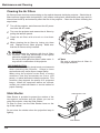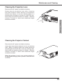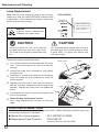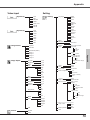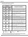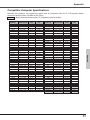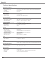
1
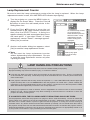
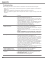
Multimedia Projector
MODEL
PLC-XW50
PLC-XW55
Owner's Manual
Features and Design
This Multimedia Projector is designed with the most advanced technology for portability, durability,
and ease of use. This projector utilizes built-in multimedia features, a palette of 16.77 million colors,
and matrix liquid crystal display (LCD) technology.
◆ Compact Design
◆ Multilanguage Menu Display
This projector is designed compact in size
and weight. It is easy to carry and work
anywhere you wish to use.
◆ Compatibility
The projector widely accepts various video
and computer input signals including:
C o m p u t e r s , 6 C o l o r s y s t e m s ( PA L ,
SECAM, NTSC, NTSC4.43, PAL-M, and
PAL-N), Component video, S-Video and
RGB scart.
◆ Logo Function
◆ Simple Computer System Setting
The projector has the Multi-scan system
to conform to almost all computer output
signals quickly. (p.26)
The digital zoom function expands (to
approx. 16 times of the screen size) the
image size, allowing you to focus on crucial
information during the presentation. (p.33)
The Logo function allows you to customize
the screen logo with the Logo functions.
(p.42-44) You can capture an image for
the screen logo, choose a logo between
provided and captured.
◆ Power Management
◆ Digital Zoom (for Computer)
Operation menu is available in 16
languages: English, German, French,
Italian, Spanish, Portuguese, Dutch,
Swedish, Finnish, Polish, Hungarian,
Romanian, Russian, Chinese, Korean, and
Japanese. (p.41)
The Power management function reduces
power consumption and maintains the
lamp life. (p.46)
◆ Lamp Control
Brightness of the projection lamp can be
selected. (p.47)
◆ Noise Reduction function
◆ Security Function
The Noise reduction function helps you to
reduce the contained noise on the screen
to get smoother images. (p.39)
◆ Blackboard Function
Blackboard* can be used as a projection
screen.
*The board color is limited to Green. (p.30, 37)
◆ Input Search Function
✔ Note:
The Security function helps you to ensure
the security with the Key lock (p.48) and
the PIN code lock (p.18, 48, 49) functions.
You can lock the operation on the projector
and the remote control. Also you can
prevent unauthorized persons from using
the projector.
Input signal can be searched automatically.
(p.45)
•The On-Screen Menu and figures in this manual may differ slightly from the product.
•The contents of this manual are subject to change without notice.
Table of Contents
Features and Design . . . . . . . . . . . . . 2
Table of Contents . . . . . . . . . . . . . . . 3
To the Owner . . . . . . . . . . . . . . . . . . . 4
Safety Instructions . . . . . . . . . . . . . . 5
Air Circulation
6
Installing the Projector in Proper
Position
6
Moving the Projector
6
Compliance . . . . . . . . . . . . . . . . . . . . 7
Part Names and Functions . . . . . . . . 8
Front
Back
8
8
Rear Terminal
Top Control
Remote Control
Remote Control Battery Installation
Operating Range
9
10
11
12
12
Bottom
8
Installation . . . . . . . . . . . . . . . . . . . . . 13
Positioning the Projector
Adjustable Foot
Connecting the AC Power Cord
Connecting to a Computer
Connecting to Video Equipment
Connecting to Component Video
Equipment
13
13
14
15
16
17
Basic Operation . . . . . . . . . . . . . . . . . 18
Turning On the Projector
18
Turning Off the Projector
19
How to Operate the On-Screen Menu20
Menu Bar21
Zoom Adjustment22
Screen Position Adjustment22
Focus Adjustment22
Keystone Correction22
Sound Adjustment23
Remote Control Operation23
Computer Input . . . . . . . . . . . . . . . . . 25
Input Source Selection25
Computer System Selection26
Auto PC Adjustment27
Manual PC Adjustment28
Image Level Selection 30
Image Level Adjustment
31
Screen Size Adjustment
32
Video Input . . . . . . . . . . . . . . . . . . . . . 34
Input Source Selection (Video)
Input Source Selection (S-Video,
Component, RGB Scart 21-pin)
Video System Selection
Image Level Selection Image Level Adjustment
Screen Size Adjustment
34
Setting
41
Warning Indicator
Cleaning the Air Filters
Slide Shutter
Cleaning the Projection Lens
Cleaning the Projector Cabinet
Lamp Replacement
Lamp Replacement Counter
51
52
52
53
53
54
55
Troubleshooting
Menu Tree
Indicators and Projector Condition
Compatible Computer Specifications
Technical Specifications
Optional Parts
Configurations of Terminals
PIN Code Number Memo
56
58
60
61
62
63
64
65
35
36
37
38
40
Setting . . . . . . . . . . . . . . . . . . . . . . . . 41
Maintenance and Cleaning . . . . . . . . 51
Appendix . . . . . . . . . . . . . . . . . . . . . . 56
Trademarks
Each name of corporations or products in this book is either a registered trademark or a trademark of its
respective corporation.
To the Owner
Before operating this projector, read this manual
thoroughly and operate the projector properly.
This projector provides many convenient features and
functions. Operating the projector properly enables
you to manage those features and maintains it in
better condition for a considerable time.
Improper operation may result in not only shortening
the product-life, but also malfunctions, fire hazard, or
other accidents.
If your projector seems to operate improperly,
read this manual again, check operations and
cable connections and try the solutions in the
"Troubleshooting" section on pages 56-57 of this
manual. If the problem still persists, contact the
dealer where you purchased the projector or the
service center.
CAUTION
RISK OF ELECTRIC SHOCK
DO NOT OPEN
CAUTION:
TO REDUCE THE RISK OF ELECTRIC
SHOCK, DO NOT REMOVE COVER (OR
BACK). NO USER-SERVICEABLE PARTS
INSIDE EXCEPT LAMP REPLACEMENT.
REFER SERVICING TO QUALIFIED
SERVICE PERSONNEL.
THIS SYMBOL INDICATES THAT DANGEROUS
VOLTAGE CONSTITUTING A RISK OF ELECTRIC
SHOCK IS PRESENT WITHIN THIS UNIT.
THIS SYMBOL INDICATES THAT THERE ARE
IMPORTANT OPERATING AND MAINTENANCE
INSTRUCTIONS IN THE OWNER'S MANUAL WITH
THIS UNIT.
NOTE:This symbol and recycle system are applied to EU
countries only and not applied to the countries in the
other area of the world.
Your SANYO product is designed
and manufactured with high quality
materials and components which
can be recycled and reused.
This symbol means that electrical
and electronic equipment, at their
end-of-life, should be disposed of
separately from your household
waste.
Please dispose of this equipment at your local
community waste collection/recycling centre. In
the European Union there are separate collection
systems for used electrical and electronic products.
Please help us to conserve the environment we live
in!
WARNING:
Safety Precaution
TO REDUCE THE RISK OF FIRE OR
ELECTRIC SHOCK, DO NOT EXPOSE THIS
APPLIANCE TO RAIN OR MOISTURE.
– This projector produces intense light from the
projection lens. Do not stare directly into the lens
as much as possible. Eye damage could result.
Be especially careful that children do not stare
directly into the beam.
– Install the projector in a proper position. If not, it
may result in a fire hazard.
– Allowing the proper amount of space on the
top, sides, and rear of the projector is critical for
proper air circulation and cooling of the unit. The
dimensions shown here indicate the minimum
space required. If the projector is to be built into a
compartment or similarly enclosed, these minimum
distances must be maintained.
– Do not cover the ventilation slot on the projector. Heat build-up can reduce the service life of your
projector, and can also be dangerous.
SIDE and TOP
REAR
0.7'(0cm)
1.5'(50cm)
3'(1m)
1.5'(50cm)
– If the projector is not to be used for an extended
time, unplug the projector from the power outlet.
CAUTION ON HANGING FROM THE CEILING
When hanging the projector from the
ceiling, clean air intake vents, air filters,
or top of the projector periodically with
a vacuum cleaner. If you leave the
projector unclean for a long time, the
dust will block the operation of the
cooling function, and it may cause a
breakdown or a disaster.
Do not set the projector in greasy, wet,
or smoky conditions such as IN a kitchen
to prevent A Breakdown or a disaster. If
The PROJECTor comes in contact with oil or
chemicals, IT may become deteriorated.
CAUTION
Not for use in a computer room as defined in the
Standard for the Protection of Electronic Computer/
Data Processing Equipment, ANSI/NFPA 75.
Ne peut être utilisé dans une salle d’ordinateurs telle
que définie dans la norme ANSI/NFPA 75 Standard
for Protection of Electronic Computer/Data Processing
Equipment.
READ AND KEEP THIS OWNER'S MANUAL FOR LATER
USE.
Safety Instructions
All the safety and operating instructions should be read
before the product is operated.
Read all of the instructions given here and retain them
for later use. Unplug this projector from AC power
supply before cleaning. Do not use liquid or aerosol
cleaners. Use a damp cloth for cleaning.
Follow all warnings and instructions marked on the
projector.
For added protection to the projector during a lightning
storm, or when it is left unattended and unused for long
periods of time, unplug it from the wall outlet. This
will prevent damage due to lightning and power line
surges.
Do not expose this unit to rain or use near water... for
example, in a wet basement, near a swimming pool,
etc...
Do not use attachments not recommended by the
manufacturer as they may cause hazards.
Do not place this projector on an unstable cart, stand,
or table. The projector may fall, causing serious injury
to a child or adult, and serious damage to the projector.
Use only with a cart or stand recommended by the
manufacturer, or sold with the projector. Wall or shelf
mounting should follow the manufacturer's instructions,
and should use a mounting kit approved by the
manufacturers.
An appliance and cart combination
should be moved with care.
Quick stops, excessive force, and
uneven surfaces may cause the
appliance and cart combination to
overturn.
Slots and openings in the back and bottom of the
cabinet are provided for ventilation, to ensure reliable
operation of the equipment and to protect it from
overheating.
The openings should never be covered with cloth or
other materials, and the bottom opening should not be
blocked by placing the projector on a bed, sofa, rug, or
other similar surface. This projector should never be
placed near or over a radiator or heat register.
Do not install the projector near the ventilation duct of
air-conditioning equipment.
This projector should be operated only from the type
of power source indicated on the marking label. If you
are not sure of the type of power supplied, consult your
authorized dealer or local power company.
Do not overload wall outlets and extension cords as
this can result in fire or electric shock. Do not allow
anything to rest on the power cord. Do not locate this
projector where the cord may be damaged by persons
walking on it.
Do not attempt to service this projector yourself
as opening or removing covers may expose you
to dangerous voltage or other hazards. Refer all
servicing to qualified service personnel.
Unplug this projector from wall outlet and refer
servicing to qualified service personnel under the
following conditions:
a.When the power cord or plug is damaged or frayed.
b.If liquid has been spilled into the projector.
c.If the projector has been exposed to rain or water.
d.If the projector does not operate normally by
following the operating instructions. Adjust only
those controls that are covered by the operating
instructions as improper adjustment of other controls
may result in damage and will often require extensive
work by a qualified technician to restore the projector
to normal operation.
e.If the projector has been dropped or the cabinet has
been damaged.
f.When the projector exhibits a distinct change in
performance-this indicates a need for service.
When replacement parts are required, be sure the
service technician has used replacement parts
specified by the manufacturer that have the same
characteristics as the original part. Unauthorized
substitutions may result in fire, electric shock, or injury
to persons.
Upon completion of any service or repairs to this
projector, ask the service technician to perform routine
safety checks to determine that the projector is in safe
operating condition.
Voor de klanten in Nederland
This projector should not be placed in a builtin installation such as a book case unless proper
ventilation is provided.
Never push objects of any kind into this projector
through cabinet slots as they may touch dangerous
voltage points or short out parts that could result in a
fire or electric shock. Never spill liquid of any kind on
the projector.
NL
Bij dit produkt zijn batterijen
geleverd.
Wanneer deze leeg zijn, moet u ze
niet weggooien maar inleveren als
KCA.
Safety Instructions
Air Circulation
Openings in the cabinet are provided for ventilation
and to ensure reliable operation of the product and to
protect it from overheating, and these openings must
not be blocked or covered.
CAUTION
Installing the Projector
in Proper Position
Install the projector properly. Improper Installation
may reduce the lamp life and cause a fire hazard.
20˚
Hot air is exhausted from the exhaust vent. When
using or installing the projector, the following
precautions should be taken.
–Do not put any flammable object or spray can
near the projector, hot air is exhausted from the
ventilation holes.
–Keep the exhaust vent at least 3' (1 m) away from
any objects.
–Do not touch a peripheral part of the exhaust vent,
especially screws and metallic part. This area will
become hot while the projector is being used.
–Do not put anything on the cabinet. Objects put
on the cabinet will not only get damaged but also
cause fire hazard by heat.
Cooling fans are provided to cool down the
projector. The fans’ running speed is changed
according to the temperature inside the projector.
Do not tilt the projector more than
20 degrees from side to side.
20˚
Do not point the projector up to
project an image.
Do not point the projector down
to project an image.
Do not put the projector on either
side to project an image.
Moving the Projector
Air Intake Vent
Air Intake Vent
Exhaust Vent
(Hot air exhaust)
Air Intake Vent
Exhaust Vent
(Hot air exhaust)
When moving the projector, close the lens shutter and
retract the adjustable foot to prevent damage to the
lens and cabinet. When the projector is not in use
for an extended period, put it into a suitable case to
protect the projector.
When handling the projector, do not drop, bump,
subject it to strong forces, or put other things on the
cabinet.
USE CAUTION IN CARRYING OR
TRANSPORTING THE PROJECTOR
–Do not drop or bump the projector, otherwise
damages or malfunctions may result.
–When carrying the projector, use a suitable
carrying case.
–Do not transport the projector by using a courier
or transport service in an unsuitable transport
case. This may cause damage to the projector.
To transport the projector through a courier or
transport service, consult your dealer for their
information.
–Do not put the projector in a case before the
projector is cooled enough.
Compliance
Federal Communication Commission Notice
Note: This equipment has been tested and found to comply with the limits for a Class B digital device,
pursuant to Part 15 of the FCC Rules. These limits are designed to provide reasonable protection against
harmful interference in a residential installation. This equipment generates, uses, and can radiate radio
frequency energy, and if not installed and used in accordance with the instructions, may cause harmful
interference to radio communications. However, there is no guarantee that interference will not occur in a
particular installation. If this equipment does cause harmful interference to radio or television reception,
which can be determined by turning the equipment off and on, the user is encouraged to try to correct the
interference by one or more of the following measures:
–Reorient or relocate the receiving antenna.
–Increase the separation between the equipment and receiver.
–Connect the equipment into an outlet on a circuit different from that to which the receiver is connected.
–Consult the dealer or an experienced radio/TV technician for help.
Use of shielded cable is required to comply with class B limits in Subpart B of Part 15 of FCC Rules.
Do not make any changes or modifications to the equipment unless otherwise specified in the instructions. If
such changes or modifications should be made, you could be required to stop operation of the equipment.
Model Number
: PLC-XW50/PLC-XW55
Trade Name
: Sanyo
Responsible party : SANYO FISHER COMPANY
Address
: 21605 Plummer Street, Chatsworth, California 91311
Telephone No.
: (818)998-7322
AC Power Cord Requirement
The AC Power Cord supplied with this projector meets the requirement for use in the country you purchased it.
AC Power Cord for the United States and Canada:
AC Power Cord used in the United States and Canada is listed by the Underwriters
Laboratories (UL) and certified by the Canadian Standard Association (CSA).
AC Power Cord has a grounding-type AC line plug. This is a safety feature to be sure
that the plug will fit into the power outlet. Do not try to defeat this safety feature. Should
you be unable to insert the plug into the outlet, contact your electrician.
GROUND
AC Power Cord for the United Kingdom:
This cord is already fitted with a moulded plug incorporating a fuse, the value of which is indicated on the pin
face of the plug. Should the fuse need to be replaced, an ASTA approved BS 1362 fuse must be used of the
same rating, marked thus
. If the fuse cover is detachable, never use the plug with the cover omitted. If a
replacement fuse cover is required, ensure it is of the same colour as that visible on the pin face of the plug
(i.e. red or orange). Fuse covers are available from the Parts Department indicated in your User Instructions.
If the plug supplied is not suitable for your socket outlet, it should be cut off and destroyed.
The end of the flexible cord should be suitably prepared and the correct plug fitted. (See Over)
WARNING : A PLUG WITH BARED FLEXIBLE CORD IS HAZARDOUS IF ENGAGED IN A LIVE SOCKET
OUTLET.
The Wires in this mains lead are coloured in accordance with the following code:
Green-and-yellow . . . . . . . Earth
Blue . . . . . . . . . . . . . . . . . Neutral
Brown . . . . . . . . . . . . . . . . Live
As the colours of the wires in the mains lead of this apparatus may not correspond with the coloured
markings identifying the terminals in your plug proceed as follows:
The wire which is coloured green-and-yellow must be connected to the terminal in the plug which is marked
by the letter E or by the safety earth symbol
or coloured green or green-and-yellow.
The wire which is coloured blue must be connected to the terminal which is marked with the letter N or
coloured black.
The wire which is coloured brown must be connected to the terminal which is marked with the letter L or
coloured red.
WARNING: THIS APPARATUS MUST BE EARTHED.
ASA
THE SOCKET-OUTLET SHOULD BE INSTALLED NEAR THE EQUIPMENT AND EASILY ACCESSIBLE.
Part Names and Functions
Front
q Speaker
w Focus Ring
e Infrared Remote Receiver
r Projection Lens
t Slide Shutter
(See page 52.)
ySlide Shutter Lever
uAir Intake Vent
q
wer t y
i Exhaust Vents
u
CAUTION
Back
i
i
o !0
!1 u
Hot air is exhausted from the exhaust vent.
Do not put heat-sensitive objects near this
side.
o Power Cord Connector
!0 Top Controls and Indicators
!1 Terminals and Connectors
!2 Air Intake Vents (back and bottom)
!3 Adjustable Foot
!4 Lamp Cover
!5 Air Filters
✽
✽ Kensington Security Slot
This slot is for a Kensington lock used to
deter theft of the projector.
Bottom
*Kensington is a registered trademark of ACCO
Brands Corporation.
!2
!3
!5
!4
i
Part Names and Functions
q
w
e
r
t
Part Names and Functions
Rear Terminal
y
u
q SERVICE PORT
This jack is used to service the projector.
w COMPUTER IN /S-VIDEO IN
/COMPONENT IN
Connect output signal from a computer,
RGB scart 21-pin video output, S-VIDEO
output, or component video output to this
terminal. (p.15-17)
y VIDEO IN
Connect the composite video output from
video equipment to VIDEO jack. (p.16)
u AUDIO IN
Connect the audio output from video
equipment connected to w or y to this
jack. (When the audio output is monaural,
connect it to L (MONO) jack.) (p.16)
e MONITOR OUT
This terminal can be used to output the
incoming signal from COMPUTER IN/
S-VIDEO IN/COMPONENT IN terminal to
the other monitor. (p.15, 17)
r AUDIO OUT (VARIABLE)
Connect an external audio amplifier to this
jack. (p.15 - 17)
This terminal outputs sound from AUDIO IN
terminal (t or u).
t COMPONENT/ COMPUTER AUDIO IN
Connect the audio output (stereo) from a
computer or video equipment connected to
w to this jack. (p.15, 17)
Part Names and Functions
Top Control
u
y
t
r
e
w
i
o
q
q MENU button
Open or close the On-Screen Menu. (p.20)
w KEYSTONE ed buttons ✽
Correct the keystone distortion. (p.22, 41)
u LAMP REPLACE indicator
Turn yellow when the life of the projection
lamp draws to an end. (p.54, 60)
i ZOOM +/- (7 8) buttons ✽
Adjust the screen size. (p.22, 41)
r POWER ON/STAND-BY button
–Execute the selected item. (p.20)
–Expand or compress the image in Digital
zoom mode. (p.33)
tPOWER indicator
✽ POINT (ed7 8) buttons
eINPUT button
Select input source. (p.25, 34, 35)
Turn the projector on or off. (p.18, 19)
Emit a red light until the projector gets
ready to be turned on. It turns red when
the projector is in the stand-by mode. It
remains green while the projector is under
operation. (p.18, 19, 60)
y WARNING indicator
10
Emit a red light when the projector detects
an abnormal condition. This also blinks
red when the internal temperature of the
projector exceeds the operating range.
(p.51, 60)
o SELECT button
w and i can be used as the point (ed7 8)
–Select an item or adjust the value in the
On-Screen Menu. (p.20)
–Pan the image in Digital zoom + mode.
(p.33)
buttons.
Part Names and Functions
Part Names and Functions
Remote Control
q POWER ON/STAND-BY button
e
w
Turn the projector on or off. (p.18, 19)
Select VIDEO input source. (p.23, 34)
Select COMPUTER input source. (p.23, 25, 35)
Open or close the On-Screen Menu. (p20)
w VIDEO button
q
e COMPUTER button
r MENU button
t Point ed 7 8 (VOLUME + / –) buttons
!5
r
t
!4
y
– Select an item or adjust the value in the OnScreen Menu. (p.20)
– Pan the image in Digital zoom + mode. (p.33)
– Adjust the volume level. (Point 7 8 buttons) (p.23)
y SELECT button
– Execute the selected item. (p.20)
– Expand or compress the image in Digital zoom
mode. (p.33)
u D.ZOOM ed buttons
Zoom in and out the images. (p.24, 33)
i FREEZE button
Freeze the picture. (p.23)
!3
o NO SHOW button
!2
!0 LAMP CONTROL button
!1
!1 MUTE button
u
Temporarily turn off the image on the screen. (p.24)
Select the lamp mode. (p.24, 47)
Mute the sound. (p.23)
Operate the P-timer function. (p.24)
Select the image level. (p.24, 30, 37)
Automatically adjust the computer image to its
optimum setting. (p.24, 27)
!2 P-TIMER button
!3 IMAGE button
!4 AUTO PC button
io
!0
!5 KEYSTONE button
Correct the keystone distortion. (p.22, 41)
To ensure safe operation, please observe the following
precautions:
–Do not bend, drop or expose the remote control to
moisture or heat.
–For cleaning, use soft dry cloth. Do not apply
benzene, thinner, splay or any chemical material.
11
Part Names and Functions
Remote Control Battery Installation
1
Open the battery
compartment lid.
2
3
Install new batteries
into the compartment.
Replace the
compartment lid.
Two AA size batteries
For correct polarity
(+ and –), be sure
battery terminals are in
contact with pins in the
compartment.
To insure safe operation, please observe the following precautions:
●Use two (2) AA or LR6 type alkaline batteries.
●Always replace batteries in sets.
●Do not use a new battery with a used battery.
●Avoid contact with water or liquid.
●Do not expose the remote control to moisture or heat.
●Do not drop the remote control.
●If the battery has leaked on the remote control, carefully wipe the case clean and install
new batteries.
●Risk of explosion if a battery is replaced by an incorrect type.
●Dispose of used batteries according to the instructions.
Operating Range
Point the remote control toward the
projector (Infrared Remote Receiver)
when pressing any button. Maximum
operating range for the remote control is
about 16.4' (5 m) and 60° in front of the
projector.
12
16.4'
(5 m)
30°
30°
Installation
Positioning the Projector
For projector positioning, see the figures below. The projector should be set horizontally to the flat
screen.
✔ Note:
•The brightness in the room has a great influence on picture quality. It is recommended to limit
ambient lighting in order to obtain the best image.
•The values shown below are approximate and may vary from the actual sizes.
32.6' (9.9 m)
A:B = 6:1
(Inch Diagonal)
Installation
21.7' (6.6 m)
16.3' (5.0 m)
300"
10.8' (3.3 m)
200"
4.3' (1.3 m)
A
150"
100"
40"
B
(Center)
Screen Size
(W x H) mm
4 : 3 aspect ratio
813 x 610
2032 x 1524
3048 x 2286
4064 x 3048
6096 x 4572
Throw distance
4.3' (1.3 m)
10.8' (3.3 m)
16.3' (5.0 m)
21.7' (6.6 m)
32.6' (9.9 m)
40"
100"
150"
200"
300"
Adjustable Foot
Projection angle can be adjusted up to 10.0 degrees
with the adjustable foot.
Press the Foot Lock Latch upward to release the
adjustable foot. At the desirable angle, release the
latch to lock the adjustable foot. Rotate the adjustable
foot from side to side for fine adjust.
Keystone distortion of the projected image can be
corrected by menu operation. (p.22, 41)
Foot Lock Latch
(Press upward)
Adjustable Foot
13
Installation
Connecting the AC Power Cord
This projector uses nominal input voltages of 100-120 V
or 200-240 V AC and it automatically selects the correct
input voltage. It is designed to work with single-phase
power systems having a grounded neutral conductor.
To reduce the risk of electrical shock, do not plug into
any other type of power system.
If you are not sure of the type of power being supplied,
consult your authorized dealer or service station.
Connect the projector with all peripheral equipment
before turning the projector on. (See pages 15-17 for
connection.)
Connect the AC power cord (supplied) to the
projector.
The AC outlet must be near this equipment
and must be easily accessible.
CAUTION
For safety, unplug the AC power cord when the projector is
not in use. When this projector is connected to an outlet with
the AC power cord, it is in Stand-by mode and consumes a
little electric power.
NOTE ON THE POWER CORD
AC power cord must meet requirements of the country where you use the projector.
Confirm the AC plug type with the chart below and proper AC power cord must be used.
If supplied AC power cord does not match your AC outlet, contact your sales dealer.
Projector side
AC outlet side
For the U.S.A. and Canada
For Continental Europe
For the U.K.
Ground
To power cord
connector on your
projector.
14
To the AC outlet.
(120 V AC)
To the AC outlet.
(200 - 240 V AC)
To the AC outlet.
(200 - 240 V AC)
Installation
Connecting to a Computer
Cables used for connection
• VGA Cables (Mini D-sub 15 pin) (Only one cable is supplied.)
• Audio Cables (Mini Plug: stereo)
( Not all the cables are supplied with this projector.)
External Audio Equipment
Monitor
Input
VGA cable
Installation
Monitor
Output
Audio Output
Audio Input
VGA
cable
Audio cable
(stereo)
Audio cable
(stereo)
COMPUTER IN
MONITOR
/S-VIDEO IN
OUT
/COMPONENT IN
AUDIO OUT
(stereo)
COMPONENT
/COMPUTER
AUDIO IN
✔ Note:
•Input sound to the COMPONENT/COMPUTER
AUDIO IN terminal when using the COMPUTER IN
/S-VIDEO IN/COMPONENT IN terminal as input.
•When connecting the AUDIO OUT to external
audio equipment, the projector's built-in speaker is
disconnected.
•See page 63 for ordering optional cables.
Unplug the power cords of
both the projector and external
equipment from the AC outlet
before connecting cables.
15
Installation
Connecting to Video Equipment
Cables used for connection
• Video and Audio Cable (RCA x 3)
• S-Video Cable
• S-Video-VGA Cable
• Audio Cables (RCA X 2, Mini Plug: stereo)
( Not all the cables are supplied with this projector.)
S-Video Output
(R)
Composite Video and Audio Output
(L)
(R) (L)
(Video)
External Audio Equipment
S-Video cable
Audio cable
Video and
Audio cable
Audio Input
S-Video-VGA cable
S-VIDEO
(R) (L)
(R) (L)
AUDIO IN
(Video)
VIDEO IN
Audio cable
AUDIO OUT
(stereo)
✔ Note:
•When connecting AUDIO OUT to external audio
equipment, the projector’s built-in speaker is
disconnected.
•See page 63 for ordering optional cables.
Unplug the power cords of both the projector
and external equipment from the AC outlet
before connecting cables.
16
Installation
Connecting to Component Video Equipment
Cables used for connection
• Audio Cables (Mini Plug :stereo)
• Scart-VGA Cable
• Component Cable
• Component-VGA Cable
( Not all the cables are supplied with this projector.)
RGB Scart
21-pin Output
Installation
Audio Output
Component Video Output
(Y, Pb/Cb, Pr/Cr)
Component
cable
Audio cable
(stereo)
Component-VGA
cable
Scart-VGA
cable
COMPUTER IN /S-VIDEO IN
/COMPONENT IN
External Audio Equipment
Audio Input
Audio cable
(stereo)
AUDIO OUT
(stereo)
COMPONENT/
COMPUTER
AUDIO IN
✔ Note:
•When connecting AUDIO OUT to external audio
equipment, the projector's built-in speaker is
disconnected.
•See page 63 for ordering optional cables.
Unplug the power cords of both the projector
and external equipment from the AC outlet
before connecting cables.
17
Basic Operation
Turning On the Projector
1
2
3
4
Complete peripheral connections (with a computer,
VCR, etc.) before turning on the projector.
Connect the projector's AC power cord into an AC
outlet. The POWER indicator becomes red.
Open the Lens Shutter by sliding the Lens Shutter
Lever.(see page 8)
Press the POWER ON/STAND-BY button on the
top control or on the remote control. The POWER
indicator becomes green and the cooling fans start
to operate. The preparation display appears on the
screen and the count down starts.
After the countdown, the input source that was
selected the last time and the Lamp mode status
icon (see page 47) appears on the screen.
If the projector is locked with a PIN code, PIN code
Input Dialog Box appears. Enter the PIN code as
instructed below.
16
The preparation display disappears after 30
seconds.
Selected Input Source and Lamp Mode
Lamp mode
(See page 47 for Lamp mode.)
PIN Code Input Dialog Box
To Enter a PIN code
Select a number by pressing the Point ed buttons,
and then press the Point 8 button to fix the number
and move the pointer. The number changes to "✳". If
you fixed an incorrect number, move the pointer to the
number you want to correct by pressing the Point 7
button, and then select the correct number by pressing
the Point ed buttons.
Repeat this step to complete entering a four-digit
number.
"1234" is set as the initial PIN code at the factory.
After entering the four-digit number, move the pointer
to "Set" by pressing the Point 8 button. Press the
SELECT button so that you can start to operate the
projector.
If you entered an incorrect PIN code, "PIN code" and
the number (✳✳✳✳) turns red. Enter the PIN code all
over again.
What is PIN code?
PIN (Personal Identification Number) code that allows
the person who knows it to operate the projector.
Setting a PIN code prevents unauthorized use of the
projector.
A PIN code consists of a four-digit number. Refer to the
PIN code lock function in the Setting on pages 48 and
49 for locking operation of the projector with your PIN
code.
After the OK icon
disappears, you can
operate the projector.
✔ Note:
•When the Input Search function is set
on On1 or On2, the input signal will
be searched automatically (p.45)
•When the Logo select function is off,
the logo is not shown on the screen.
(p.42)
•When the "Countdown off" or "Off"
is selected in the Display function,
the countdown is not shown on the
screen. (p.42)
•During the countdown period, all
operations are invalid.
•If the correct PIN code number is
not input for three minutes after the
PIN code dialog box appeared, the
projector is turned off automatically.
CAUTION ON HANDLING PIN CODE
If you forget your PIN code, the projector can no longer be started. Set a new PIN code with special care,
write it down in column on page 65 of this manual, and keep it at hand. Should the PIN code be missing
or forgotten, consult your dealer or service center.
18
Basic Operation
Turning Off the Projector
1
2
3
Press the POWER ON/STAND-BY button on
the top control or on the remote control, and a
message "Power off?" appears on the screen.
Press the POWER ON/STAND-BY button again
to turn off the projector. The POWER indicator
starts to blink red, and it continues while the
cooling fans are operating for about 90 seconds.
(You can select the level of fan quietness and
rotation speed. See page 50.)
At this time you can disconnect the AC power
cord even if the fans are still running.
The message disappears after 4 seconds.
When the projector has cooled down enough to
be turned on again, the POWER indicator lights
red.
TO MAINTAIN THE LIFE OF THE LAMP, ONCE YOU
TURN THE PROJECTOR ON, WAIT AT LEAST FIVE
MINUTES BEFORE TURNING IT OFF.
Basic Operation
✔ Note:
•When the On start function is on, this projector
is turned on automatically by connecting the AC
power cord to an AC outlet. (p.47)
•Do not operate the projector continuously without
rest. Continuous use may result in shortening
the lamp life. Turn off the projector and give it a
rest about an hour in every 24 hours.
•The running speed of cooling fans is changed
according to the temperature inside the projector.
•D o not put the projector in a case before the
projector is cooled enough.
•If the WARNING indicator blinks or emits a red
light, see "Warning Indicator" on page 51.
•While the POWER indicator is blinking, lamp
is being cooled down and the projector cannot
be turned on. Wait until the POWER indicator
becomes red to be turned on again.
19
Basic Operation
How to Operate the On-Screen Menu
The projector can be adjusted or set via the On-Screen
Menu. Refer to the following pages regarding each
adjustment and setting procedures.
1
Top Control
Press the MENU button to display the On-Screen
Menu.
2
Press the Point 7 8 buttons to select a Menu icon
to adjust and press the Point ed buttons to select
an item to adjust.
3
Press the SELECT button to show the item data.
To adjust the data, press the Point 7 8 buttons.
Refer to the following pages for each adjustment.
SELECT button
MENU button
Remote Control
MENU button
To close the On-Screen Menu, press the MENU
button again.
POINT buttons
✔ Note:
The selected item is not active until the SELECT
button is pressed.
SELECT button
Menu icon
On-Screen Menu
Menu bar
Pointer
(red framed )
Pointer (red framed )
Press the Point ed buttons to
move the pointer.
Item
SELECT
button
Item data
Press the Point 7 8
buttons to adjust the
value.
Quit
Exit this menu.
20
Basic Operation
Menu Bar
For detailed functions, see Menu Tree on p.58, 59.
For computer source
Guide Window
Show the selected
Menu of the
On-Screen Menu.
PC System Menu
Image Select Menu Screen Menu
Used to select computer Used to select an
system. (p.26)
image level among
Dynamic, Standard,
Real, Blackboard
(Green), and Image
1 ~ 4. (p.30)
Used to select
input source either
Computer or
Video. (p.25)
PC Adjust Menu
Used to adjust
parameters to match
with input signal
format. (p.27-29)
Image Adjust Menu
Setting Menu
Used to set
the projector's
operating
configurations.
(p.41-50)
Sound Menu
Used to adjust computer
image.[Contrast /
Brightness / Color temp.
/ White balance (R/G/B)
/ Sharpness / Gamma]
(p.31, 32)
Used to adjust the
volume or mute the
sound. (p.23)
For video source
Input Menu
Used to select input
source either Video or
Computer. (p.34, 35)
Same function as
menu for computer
source.
Image Select Menu
Used to select an image level among
Dynamic, Standard, Cinema, Blackboard
(Green) and Image 1 ~ 4. (p.37)
AV System Menu
Used to select system
of selected video
source. (p.36)
Image Adjust Menu
Screen Menu
Used to set size of
image to Normal or
Wide. (p.40)
Used to adjust picture image.
[Contrast / Brightness / Color / Tint
/ Color temp. / White balance (R/
G/B) / Sharpness / Gamma / Noise
reduction / Progressive ] (p.38-39)
Same function
as computer
menu.
21
Basic Operation
Input Menu
Used to adjust size of
image. [Normal / True
/ Wide / Full screen
/ Digital zoom +/–]
(p.32, 33)
Basic Operation
Zoom Adjustment
Press the ZOOM +/- buttons on the top control to
adjust the screen size. Screen size can be adjusted
80% to 100% from it's maximum screen size.
Top Control
ZOOM +/- buttons
It is not available when On-Screen menu is displayed.
Zoom adjustment can be memorized. (p.41)
Screen Position Adjustment
Screen position can be adjusted in the Zoom
Adjustment.
1
2
3
Focus Ring
Press the ZOOM+ or ZOOM- buttons on the top
control.
While ZOOM+ or ZOOM- is displayed on the
screen, press the SELECT button. Arrow marks
displayed on the screen.
Press the point ed7 8buttons to adjust screen
positions.
Screen position can not be adjusted at ZOOM
maximum.
Focus Adjustment
Rotate the Focus Ring to adjust the projected picture
focus.
Keystone Correction
If a projected picture has keystone distortion, correct
the image with Keystone adjustment.
It is not available when On-Screen menu is displayed.
•The arrows are white when there is no
correction.
•The direction of the arrow being corrected
turns red.
•The arrows disappear at the maximum
correction.
•If you press the KEYSTONE button on
the remote control once more while the
keystone dialog box is being displayed, the
keystone adjustment is canceled.
Top Control
Press the KEYSTONE ed buttons on the top control
or the KEYSTONE button on the remote control. The
keystone dialog box appears.
Correct keystone distortion by pressing the
KEYSTONE ed buttons on the top control or the
Point ed buttons on the remote control. Keystone
adjustment can be memorized. (p.41)
Reduce the upper width
with KEYSTONE e button
or Point e button.
Reduce the lower width
with KEYSTONE d button
or Point d button.
KEYSTONE ed
buttons
Remote Control
KEYSTONE button
POINT ed buttons
22
Basic Operation
Sound Adjustment
Direct Operation
Remote Control
Volume
VOL+ button
Press the VOLUME+/– buttons on the remote control to
adjust the volume. The volume dialog box appears on
the screen for a few seconds.
Mute
MUTE button
Press the MUTE button on the remote control to cut off
the sound. To restore the sound to its previous level,
press the MUTE button again or press the VOLUME
+/– buttons.
Mute function is also effective for AUDIO OUT jack.
Approximate
level of the
volume.
Menu Operation
1
2
Press the MENU button to display the On-Screen
Menu. Press the Point 7 8 buttons to move the
red framed pointer to the Sound Menu icon.
Volume
Press the MUTE button to set the Mute
function On/Off. The display disappears after
4 seconds.
Sound Menu
Press the Point 8 button to turn up the volume, and
press the Point 7 button to turn down the volume.
Sound Menu
icon
Approximate level of
the volume.
Mute
Press the Point 7 8 buttons to cut off the sound.
Dialog box display changes to "On" and the sound is
cut off. To restore the sound to its previous level, press
the Point 7 8 buttons again.
Exit the Sound Menu.
Remote Control Operation
For some frequently used operations, using the remote
control is advisable.
Just pressing one of the buttons enables you to
make the operation, and no need for calling up the
On-Screen Menu.
Remote Control
COMPUTER/
VIDEO buttons
COMPUTER/VIDEO buttons
Press the COMPUTER or VIDEO button on the remote
control to select the input source. For more detail, see
pages 25, 34, and 35.
FREEZE button
FREEZE button
Press the FREEZE button on the remote control to
freeze the picture on the screen. To cancel the Freeze
function, press the FREEZE button again or press any
other button.
✔ Note:
See the next page for the other
buttons.
23
Basic Operation
Press the Point ed buttons to move the red
framed pointer to the item that you want to select,
and then press the SELECT button.
VOL- button
Basic Operation
AUTO PC button
Press the AUTO PC button on the remote control to
operate the Auto PC function. For more detail, see
page 27.
Remote Control
VOLUME +/- buttons
(See p.23.)
KEYSTONE button
(See p.22)
D.ZOOM buttons
POINT ed buttons
Press the D.ZOOM buttons on the remote control to
zoom in and zoom out the images. For more detail,
see page 33.
AUTO PC button
IMAGE button
NO SHOW button
P-TIMER button
Press the NO SHOW button on the remote control to
black out the image. To restore to normal, press the
NO SHOW button again or press any other button.
When a projected image is captured and set as "User"
in the Logo selection (p.42), the screen changes each
time you press the NO SHOW button as follows.
black out ➜ the captured image ➜ normal ➜
•••••
NO SHOW button
D.ZOOM buttons
LAMP CONTROL
button
✔ Note:
S ee the previous page for the
other buttons.
KEYSTONE button
For detail, see page 22.
IMAGE button
Press the IMAGE button on the remote control to select
a desired image level of the screen. For more detail,
see pages 30 and 37.
The message disappears after 4 seconds.
P-TIMER button
Press the P-TIMER button on the remote control. The
timer display "00 : 00" appears on the screen and the
timer starts to count time (00 : 00 ~ 59 : 59).
To stop the P-Timer, press the P-TIMER button. Press
the P-TIMER button again, then the P-timer display
disappears.
LAMP CONTROL button
Press the LAMP CONTROL button on the remote
control to select the lamp mode for changing the
brightness of the screen.
Normal. . . normal brightness
Auto. . . . . brightness according with the input
signal
Eco........... lower brightness reduces the lamp
power consumption and extends the
lamp life.
24
P-Timer display
Computer Input
Input Source Selection
Direct Operation
Top Control
Choose Computer by pressing the INPUT button
on the top control or press the COMPUTER button
on the remote control. Before using these buttons,
correct input source should be selected through Menu
operation as described below.
INPUT button
Computer
Video
Remote Control
Menu Operation
Press the MENU button to display the On-Screen
Menu. Press the Point 7 8 buttons to move the
red framed pointer to the Input Menu icon.
2
Press the Point ed buttons to move the red
arrow pointer to Computer, and then press the
SELECT button.
3
After the Source Select Menu appeared for
Computer, move the pointer to RGB and then
press the SELECT button.
Input Menu
COMPUTER button
Input Menu icon
Move the pointer (red
arrow) to Computer and
press the SELECT button.
Computer
Source Select Menu
Move the pointer to RGB
and press the SELECT
button.
✔ Note:
When the Input Search function is set On1
or On2, the input signal will be searched
automatically (p.45)
25
Computer Input
1
INPUT button
Computer Input
Computer System Selection
This projector automatically tunes to various types of computers based on VGA, SVGA, XGA,
SXGA, WXGA, or UXGA with its Multi-scan system and Auto PC Adjustment. If Computer is
selected as a signal source, this projector automatically detects the signal format and tunes to
project a proper image without any additional setting. (Signal formats provided in this projector is
shown on page 61.)
One of the following messages may appear when:
Auto
The projector cannot recognize the
connected signal conforming to the
provided PC Systems. The message "Auto"
is displayed on the PC System Menu icon
and the Auto PC Adjustment function works
to display proper images. If the image is
not projected properly, a manual adjustment
is required. (p.28, 29)
----
There is no signal input from computer.
Check the connection between your
c o m p u t e r a n d t h e p r o j e c t o r. ( S e e
"Troubleshooting" on page 56.)
Mode 1
The preset system is manually adjusted in
the PC Adjust Menu. The adjusted data can
be stored in Mode 1 ~ 5. (p.28, 29)
SVGA 1
PC Systems provided in this projector is
chosen. The projector chooses a proper
system provided in the projector and
displays it.
PC System Menu
The Auto PC Adjustment
function operates to adjust
the projector.
*Mode 1 and SVGA 1 are examples.
Selecting Computer System Manually
PC system can also be selected manually.
1
Press the MENU button to display the On-Screen
Menu. Press the Point 7 8 buttons to move the
red framed pointer to the PC System Menu icon.
2
Press the Point ed buttons to move the red arrow
pointer to the system that you want to set, and then
press the SELECT button.
26
PC System Menu
The PC System Menu icon
Selected system is displayed.
Systems on this dialog
box can be selected.
Custom Mode (1 ~ 5) set in the
PC Adjust Menu. (p.27, 29)
Computer Input
Auto PC Adjustment
Auto PC Adjustment function is provided to automatically adjust Fine sync, Total dots, Horizontal,
and Vertical to conform to your computer. Auto PC Adjustment function can be operated as follows.
Direct Operation
Remote Control
The Auto PC adjustment function can be operated
directly by pressing the AUTO PC button on the remote
control unit.
Menu Operation
AUTO PC button
PC Adjust Menu
Auto PC Adj.
1
Press the MENU button to display the On-Screen
Menu. Press the Point 7 8 buttons to move the
red framed pointer to PC Adjust Menu item.
2
Press the Point ed buttons to move the red
framed pointer to Auto PC Adj. item and then
press the SELECT button twice.
Move the red framed pointer to
the Auto PC Adj. item and press
the SELECT button.
"Please wait..." message appears
while Auto PC adjustment is in
process.
Computer Input
To store adjustment parameters
Adjustment parameters from Auto PC Adjustment can
be memorized in this projector. Once parameters are
memorized, the setting can be done just by selecting
Mode in the PC System Menu (p.26). See "Store" on
page 29.
PC Adjust Menu icon
✔ Note:
•Fine sync, Total dots, Horizontal, and Vertical of
some computers cannot be fully adjusted with this
Auto PC Adjustment function. When the image is
not provided properly with this operation, manual
adjustments are required. (p.28, 29)
•The Auto PC Adjustment cannot be operated when
480i, 575i, 480p, 575p, 720p,1035i, or 1080i is
selected in the PC System Menu. (p.26)
27
Computer Input
Manual PC Adjustment
Some computers employ special signal formats which may not be tuned by Multi-scan system
of this projector. Manual PC Adjustment enables you to precisely adjust several parameters to
match those signal formats. The projector has 5 independent memory areas to memorize those
parameters manually adjusted. It allows you to recall the setting for a specific computer.
1
Press the MENU button to display the On-Screen
Menu. Press the Point 7 8 buttons to move the
red framed pointer to the PC Adjust Menu icon.
2
Press the Point ed buttons to move the red
framed pointer to the item that you want to adjust
and then press the SELECT button to display
the adjustment dialog box. Press the Point 7 8
buttons to adjust the value.
PC Adjust Menu
PC Adjust Menu icon
Move the red framed
pointer to an item and press
the SELECT button.
Fine sync
Press the Point 7 8 buttons to adjust the value to
eliminate flicker from the image displayed. (From 0 to
31.)
Status (Stored/Free)
of the selected Mode.
Selected Mode
Total dots
Press the Point 7 8 buttons to adjust the number of
total dots in one horizontal period to match your PC
image.
Horizontal
Press the Point 7 8 buttons to adjust the horizontal
picture position.
Vertical
Press the Point 7 8 buttons to adjust the vertical
picture position.
Press the Point 7 8
buttons to adjust the
value.
Press the SELECT
button at this item to
adjust other items.
Current mode
Press the SELECT button to show H-sync freq. and
V-sync freq. of the connected computer.
Clamp
Press the Point 7 8 buttons to adjust clamp level.
When the image has dark bars, try this adjustment.
Press the SELECT button
at the Current mode item to
show the information of the
connected computer.
28
Computer Input
Display area H
Press the Point 7 8 buttons to adjust the horizontal
area displayed by this projector.
Display area V
Press the Point 7 8 buttons to adjust the vertical area
displayed by this projector.
Reset
To reset the adjusted data, select Reset and press
the SELECT button. The confirmation box appears
and then select [Yes]. All adjustments return to their
previous figures.
Mode free
To clear the stored data, select Mode free and press
the SELECT button. Move the red arrow pointer to
the Mode that you want to clear and then press the
SELECT button.
Move the red framed
pointer to an item and
press the SELECT button.
This Mode has stored parameters.
To clear adjusted data
Store
Quit
Vacant Mode
Values of "Total dots",
"Horizontal", "Vertical",
"Display area H" and
"Display area V".
Computer Input
To store the adjusted data, select Store and press the
SELECT button. Move the red arrow pointer to any of
Mode 1 to 5 in which you want to store and then press
the SELECT button.
To store adjusted data
Exit the PC Adjust Menu.
✔ Note:
Display area (H/V) cannot be selected when 480i,
575i, 480p, 575p, 720p, 1035i, or 1080i is selected
in the PC System Menu (p.26).
Close this dialog box.
29
Computer Input
Image Level Selection
Direct Operation
Select an image level among Dynamic, Standard, Real,
Blackboard (Green), Image 1, Image 2, Image 3, and
Image 4 by pressing the IMAGE button on the remote
control.
Dynamic
Picture level suitable for viewing picture in a bright
room.
Standard
Normal picture level preset on this projector.
Real
Picture level with improved halftone for graphics.
Blackboard (Green)
Picture level suitable for the image projected on a
blackboard. This mode assists to enhance the image
projected on a blackboard. This is mainly effective on
a green colored board, not truly effective on a black
colored board.
Image 1 ~ 4
User preset image in the Image Adjust Menu. (p.32)
Menu Operation
1
2
Press the MENU button to display the On-Screen
Menu. Press the Point 7 8 buttons to move the
red framed pointer to the Image Select Menu icon.
Press the Point ed buttons to move the red
framed pointer to the level that you want to set and
then press the SELECT button.
Remote Control
IMAGE button
IMAGE button
Dynamic
Standard
Real
Blackboard (Green)
Image 1
Image 2
Image 3
Image 4
Image Select Menu icon
Image Select Menu
Dynamic
Picture level suitable for viewing picture in a bright
room.
Standard
Move the red framed
pointer to the level and
press the SELECT button.
Normal picture level preset on this projector.
Real
Picture level with improved halftone for graphics.
Blackboard (Green)
Picture level suitable for the image projected on a
blackboard. See above for further description.
Image 1 ~ 4
User preset image in the Image Adjust Menu. (p.32)
30
The level being selected.
Computer Input
Image Level Adjustment
1
2
Press the MENU button to display the On-Screen
Menu. Press the Point 7 8 buttons to move the
red framed pointer to the Image Adjust Menu icon.
Image Adjust Menu
Press the Point ed buttons to move the red
framed pointer to the item that you want to adjust,
and then press the SELECT button. The level
of each item is displayed. Adjust each level by
pressing the Point 7 8 buttons.
Image Adjust Menu icon
Move the red framed
pointer to the item to be
selected and then press
the SELECT button.
Contrast
Press the Point 7 button to decrease the contrast and
the Point 8 button to increase contrast. (From 0 to 63.)
Brightness
Press the Point 7 button to adjust the image darker
and the Point 8 button to adjust the image brighter.
(From 0 to 63.)
Selected Image level
Color temp.
Press the Point 7 8 buttons to select the desired Color
temp. level. (XLow, Low, Mid, or High)
Press the Point 7 8
buttons to adjust the
value.
White balance (Red)
Press the Point 7 button to lighten the red tone and the
Point 8 button to deepen the red tone. (From 0 to 63.)
White balance (Green)
Computer Input
Press the Point 7 button to lighten the green tone and
the Point 8 button to deepen the green tone. (From 0
to 63.)
White balance (Blue)
Press the Point 7 button to lighten the blue tone and
the Point 8 button to deepen the blue tone. (From 0 to
63.)
Sharpness
Press the Point 7 button to soften the image and the
Point 8 button to sharpen the image. (From 0 to 15.)
✔ Note:
After adjusting any of the White
balance Red, Green, or Blue, the
Color temp changes to "Adj.".
Gamma
Press the Point 7 8 buttons to adjust the gamma value
to obtain better balance of contrast. (From 0 to 15.)
Reset
To reset the adjusted data, select Reset and press
the SELECT button. The confirmation box appears
and then select [Yes]. All adjustments returns to their
previous figures.
31
Computer Input
Store
To store the adjusted data, select Store and press the
SELECT button. Select a level from Image 1 to 4 with
the Point ed buttons and press the SELECT button. A
confirmation box appears and then select [Yes].
Stored data can be called up by selecting "Image" in
the Image Level Selection on page 30.
Move the red framed
pointer to any of
Image 1 to 4 where
you want to set
and then press the
SELECT button.
Quit
Exit the Image Adjust Menu.
Store item
Press the SELECT
button at this item to
store the adjusted data.
The confirmation
box appears,
then select [Yes].
Screen Size Adjustment
This projector has the picture screen resize function, which enables you to customize the image
size.
1
Press the MENU button to display the On-Screen
Menu. Press the Point 7 8 buttons to move the
red framed pointer to the Screen Menu icon.
2
Press the Point ed buttons and move the red
framed pointer to the function that you want to
select and then press the SELECT button.
Normal
Screen Menu
Screen Menu icon
Move the red framed pointer
to the function and press the
SELECT button.
Provide the image to fit the screen size.
True
Provide the image in its original size. When the original
image size is larger than the screen size (1024 x 768 ),
this projector enters panning mode automatically. Pan
the image with Point ed 7 8 buttons. When adjusted,
the arrows turns red. When reached to the correction
limit, the arrows disappears.
Wide
Provide the image to fit wide video aspect ratio (16:9)
by expanding the image width uniformly. This function
can be used for providing a squeezed video signal at
16:9.
Full screen
Provide the full screen image.
32
✔ Note:
•T h i s S c r e e n M e n u c a n n o t b e
operated when 720p(HDTV), 1035i
(HDTV), or 1080i (HDTV) is selected
in the PC System Menu (p.26).
•The projector cannot display any
resolution higher than 1280x1024.
If your computer’s screen resolution
is higher than it, reset the resolution
to the lower before connecting to the
projector.
•The image data in other than XGA
(1024x768) is modified to fit the
screen size in initial mode.
•True, Full screen, and Digital zoom
+/– cannot be selected when 480i,
575i, 480p, or 575p is selected in
the PC System Menu (p.26).
Computer Input
For zooming in and out the images
Remote Control
Digital zoom +
POINT buttons
When the D.ZOOM + (e) is pressed, the On-Screen
Menu disappears and the message "D. zoom +"
is displayed. Press the D.ZOOM e or the SELECT
button to expand the image size. And press the Point
ed 7 8 buttons to pan the image. The Panning
function can work only when the image is larger than
the screen size.
SELECT button
D.ZOOM + button
D.ZOOM - button
Digital zoom –
When D.ZOOM – ( d ) is pressed, the On-Screen
Menu disappears and the message "D. zoom –" is
displayed. Press the D.ZOOM d or the SELECT button
to compress image size.
This is used to reducing the size into original size.
To exit the Digital zoom +/– mode, press any button
except the D.ZOOM ed buttons, SELECT, and Point
buttons.
To return to the previous screen size, select a screen
size from the Screen Size Adjustment or select an input
source from the Input Source Selection (p.25) again, or
adjust the screen size with the D.ZOOM ed buttons.
✔ Note:
•T h e p a n n i n g f u n c t i o n m a y n o t
operate properly if the stored Mode
in the PC Adjust Menu is used.
(p.29)
• True, Full screen, and Digital zoom
+/– cannot be selected when 480i,
575i, 480p, or 575p is selected in
the PC System Menu (p.26).
•Digital zoom +/- cannot be selected
when Full screen or True is selected.
Computer Input
33
Video Input
Input Source Selection (Video)
Direct Operation
Top Control
INPUT button
Choose Video by pressing the INPUT button on the top
control or the VIDEO button on the remote control.
Before using these buttons, correct input source should
be selected through menu operation as described
below.
INPUT button
Video
Computer
Remote Control
VIDEO button
Menu Operation
1
Press the MENU button to display the On-Screen
Menu. Press the Point 7 8 buttons to move the red
framed pointer to the Input Menu icon.
2
Press the Point ed buttons to move the red arrow
pointer to Video and then press the SELECT
button.
34
Input Menu icon
Input Menu
Move the pointer to
Video and press the
SELECT button.
Video Input
Input Source Selection (S-Video, Component, RGB Scart 21-pin)
Direct Operation
Top Control
INPUT button
Choose Computer by pressing the INPUT button on
the top control or press the COMPUTER button on the
remote control.
Before using these buttons, correct input source should
be selected through Menu operation as described
below.
INPUT button
Computer
Video
Remote Control
COMPUTER button
COMPUTER button
Computer
Menu Operation
1
Press the MENU button to display the On-Screen
Menu. Press the Point 7 8 buttons to move the
red framed pointer to the Input Menu icon.
2
Press the Point ed buttons to move the red arrow
pointer to Computer and then press the SELECT
button.
3
After the Source Select Menu appeared
for Computer, move the pointer to S-Video,
Component or RGB (Scart) and then press the
SELECT button.
S-Video
When S-video input signal is
connected to the COMPUTER IN/
S-VIDEO IN/COMPONENT IN jack,
select S-Video.
When the input source is coming
from video equipment connected
to the COMPUTER IN/S-VIDEO
IN/COMPONENT IN terminal with
a Component-VGA Cable, select
Component.
RGB (Scart)
When the input source is coming
from video equipment connected to
the COMPUTER IN/S-VIDEO IN/
COMPONENT IN terminal with a ScartVGA Cable, select RGB (Scart).
Input Menu icon
Move the pointer (red
arrow) to Computer and
press the SELECT button.
Computer
Source Select Menu
Move the pointer to
S-Video, Component or
RGB (Scart) and press the
SELECT button.
Video Input
Component
Input Menu
✔ Note:
When the Input Search function is set On1 or On2,
the input signal will be searched automatically
(p.45)
35
Video Input
Video System Selection
1
Press the MENU button to display the On-Screen
Menu. Press the Point 7 8 buttons to move the
red framed pointer to the AV System Menu icon.
2
Press the Point ed buttons to move the red arrow
pointer to the system that you want to select and
then press the SELECT button.
Video or S-Video
AV System Menu (Video or S-Video)
Auto
The projector automatically detects incoming video
system, and adjusts itself to optimize its performance.
When Video System is PAL-M or PAL-N, select system
manually.
PAL/SECAM/NTSC/NTSC4.43/PAL-M/PAL-N
If the projector cannot reproduce proper video image,
it is necessary to select a specific broadcast signal
format among PAL, SECAM, NTSC, NTSC 4.43,
PAL-M, and PAL-N.
Component
AV System Menu icon Selected system is displayed.
Move the pointer to a
system and press the
SELECT button.
AV System Menu (Component)
Auto
The projector automatically detects incoming video
signal, and adjusts itself to optimize its performance.
COMPONENT VIDEO SIGNAL FORMAT
If the projector cannot reproduce proper video image,
it is necessary to select a specific component video
signal format among 480i, 575i, 480p, 575p, 720p,
1035i, and 1080i.
✔ Note:
The AV System Menu cannot be selected when
selecting RGB (Scart).
36
AV System Menu icon Selected system is displayed.
Move the pointer to a
system and press the
SELECT button.
Video Input
Image Level Selection
Direct Operation
Select an image level among Dynamic, Standard,
Cinema, Blackboard (Green), Image 1, Image 2, Image
3, and Image 4 by pressing the IMAGE button on the
remote control.
Dynamic
Picture level suitable for viewing picture in a bright
room.
Standard
Normal picture level preset on this projector.
Cinema
Picture level adjusted for the picture with fine tone.
Blackboard (Green)
Picture level suitable for the image projected on a
blackboard. This is mainly effective on a green colored
board, not truly effective on a black colored board.
Image 1 ~ 4
User preset image in the Image Adjust Menu (p.38, 39).
Menu Operation
1
2
Press the MENU button to display the On-Screen
Menu. Press the Point 7 8 buttons to move the
red framed pointer to the Image Select Menu icon.
Press the Point ed buttons to move the red
framed pointer to the level that you want to set and
then press the SELECT button.
Remote Control
IMAGE button
IMAGE button
Dynamic
Standard
Cinema
Blackboard (Green)
Image 1
Image 2
Image 3
Image 4
Image Select Menu icon
Image Select Menu
Dynamic
Picture level suitable for viewing picture in a bright
room.
Standard
Move the red framed
pointer to the level and
press the SELECT button.
Normal picture level preset on this projector.
Video Input
Cinema
Picture level adjusted for the picture with fine tone.
Blackboard (Green)
Picture level suitable for the image projected on a
blackboard. See above for further description.
The level being selected.
Image 1~4
User preset image in the Image Adjust Menu (p.38, 39).
37
Video Input
Image Level Adjustment
1
2
Press the MENU button to display the On-Screen
Menu. Press the Point 7 8 buttons to move the
red framed pointer to the Image Adjust Menu icon.
Press the Point ed buttons to move the red
framed pointer to the item that you want to adjust,
and then press the SELECT button. The level
of each item is displayed. Adjust each level by
pressing the Point 7 8 buttons.
Image Adjust Menu
Image Adjust Menu icon
Move the red framed
pointer to the item to be
selected and then press
the SELECT button.
Contrast
Press the Point 7 button to decrease the contrast and
the Point 8 button to increase contrast. (From 0 to 63.)
Brightness
Press the Point 7 button to adjust the image darker
and the Point 8 button to adjust the image brighter.
(From 0 to 63.)
Color
Press the Point 7 button to lighten the color and the
Point 8 button to deepen the color. (From 0 to 63.)
Tint
Press the Point 7 8 buttons to obtain a proper color.
(From 0 to 63.)
Press the Point 7 8
buttons to adjust the
value.
Press the SELECT
button at this item to
display other items.
Color temp.
Press the Point 7 8 buttons to select the desired Color
temp. level. (XLow, Low, Mid, or High)
White balance (Red)
Press the Point 7 button to lighten the red tone and the
Point 8 button to deepen the red tone.
(From 0 to 63.)
White balance (Green)
Press the Point 7 button to lighten the green tone and
the Point 8 button to deepen the green tone.
(From 0 to 63.)
White balance (Blue)
Press the Point 7 button to lighten the blue tone and
the Point 8 button to deepen the blue tone.
(From 0 to 63.)
✔ Note:
•The Tint cannot be selected when the video
system is PAL, SECAM, PAL-M, or PAL-N.
•After adjusting any of the White balance Red,
Green, or Blue, the Color temp. changes to "Adj.".
38
Press the SELECT
button at this item to
display previous items.
Video Input
Sharpness
Press the Point 7 button to soften the image and the
Point 8 button to sharpen the image. (From 0 to 15.)