1
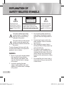
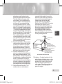
Digital Color Dome Camera User’s Guide ENG SCC-B535x(S) FRE SPA JAP AB68-00648C(01)Eng.indd 1 2007-03-22 ソタネト 3:02:16 EXPLANATION OF SAFETY RELATED SYMBOLS CAUTION RISK OF ELECTRIC SHOCK DO NOT OPEN The lighting flash and Arrowhead within Triangle is a warning sign alerting you of dangerous voltage inside the product. CAUTION: TO REDUCE THE RISK OF ELECTRIC SHOCK, DO NOT REMOVE REAR COVER. NO USER SERVICEABLE PARTS INSIDE. REFER TO QUALIFIED SERVICE PERSONNEL. This symbol indicates high voltage is present inside. It is dangerous to make any kind of contact with any inside part of this product. This symbol alerts you that important literature concerning operation and maintenance has been included with this product. To prevent damage which may result in fire or electric shock hazard, do not expose this appliance to rain or moisture. 3. 4. 5. 6. WARNING 1. 2. Be sure to use only the standard adapter that is specified in the specification sheet. Using any other adapter could cause fire, electrical shock, or damage to the product Incorrectly connecting the power supply or replacing battery may cause explosion, fire, electric shock, or damage to the product. 7. The explanation point within the triangle is a warning sign alerting you of important instructions accompanying the product. Do not connect multiple cameras to a single adapter. Exceeding the capacity may cause abnormal heat generation or fire. Securely plug the power cord into the power receptacle. Insecure connection may cause fire. When installing the camera, fasten it securely and firmly. A falling camera may cause personal injury. Do not place conductive objects (e.g. screwdrivers, coins, metal things, etc.) or containers filled with water on top of the camera. Doing so may cause personal injury due to fire, electric shock, or falling objects. Do not install the unit in humid, dusty, or sooty locations. Doing so may cause fire or electric shock. 2 B68-00648C(01)Eng.indd 2 2007-03-19 ¿ÀÀü 10:34:18 8. CAUTION 1. 2. 3. 4. 5. 6. B68-00648C(01)Eng.indd 3 Do not drop objects on the product or apply strong shock to it. Keep away from a location subject to excessive vibration or magnetic interference. Do not install in a location subject to high temperature (over 122°F, 50°C), low temperature (below 14°F, -10°C), or high humidity. Doing so may cause fire or electric shock. If you want to relocate the already installed product, be sure to turn off the power and then move or reinstall it. Remove the power plug from the outlet when then there is a lightning. Neglecting to do so may cause fire or damage to the product. Keep out of direct sunlight and heat radiation sources. It may cause fire. Install it in a place with good ventilation. 7. Avoid aiming the camera directly towards extremely bright objects such as sun, as this may damage the CCD image sensor. FCC Statement This device complies with part 15 of the FCC Rules. Operation is subject to the following two conditions: 1) This device may not cause harmful interference, and 2) This device must accept any interference received including interference that may cause undesired operation. ENG If any unusual smells or smoke come from the unit, stop using the product. In such case, immediately disconnect the power source and contact the service center. Continued use in such a condition may cause fire or electric shock. 9. If this product fails to operate normally, contact the nearest service center. Never disassemble or modify this product in any way. (SAMSUNG is not liable for problems caused by unauthorized modifications or attempted repair.) 10. When cleaning, do not spray water directly onto parts of the product. Doing so may cause fire or electric shock. Note This equipment has been tested and found to comply with the limits for a Class A digital device, pursuant to part 15 of FCC Rules. These limits are designed to provide reasonable protection against harmful interference when the equipment is operated in a commercial environment. This equipment generates, uses, and can radiate radio frequency energy and, if not installed and used in accordance with the instruction manual, may cause harmful interference to radio communications. Operation of this equipment in a residential area is likely to cause harmful interference in which case the user will be required to correct the interference at his own expense. IC Compliance Notice This Class A digital apparatus meets all requirements of the Canadian interference-Causing Equipment Regulations of ICES-003. 3 2007-03-19 ¿ÀÀü 10:34:18 IMPORTANT SAFETY INSTRUCTIONS 1. 2. 3. 4. 5. 6. 7. 8. Read Instructions – All the safety and operating instructions should be read before the product is operated. Retain Instructions – The safety and operating instructions should be retained for future reference. Heed Warnings – All warnings on the product and in the operating instructions should be adhered to. Follow Instructions – All operating and use instructions should be followed. Cleaning – Unplug this product from the wall outlet before cleaning. Do not use liquid cleaners or aerosol cleaners. Use a damp cloth for cleaning. Attachments – Do not use attachments not recommended by the product manufacturer as they may cause hazards. Water and Moisture – Do not use this product near water – for example, near a bath tub, wash bowl, kitchen sink, or laundry tub; in a wet basement; or near a swimming pool; and the like. Accessories – Do not place this product on an unstable cart, stand, tripod, bracket, or table. The product may fall, causing serious injury to a child or adult, and serious damage to the product. Use only with a cart, stand, tripod, bracket, or table recommended by the manufacturer, or sold with the product. Any mounting of the product should follow the manufacturer’s instructions, and should use a mounting accessory recommended by the manufacturer. 9. A product and cart combination should be moved with care. Quick stops, excessive force, and uneven surfaces may cause the product and cart combination to overturn. 10. Ventilation – Slots and openings in the cabinet are provided for ventilation and to ensure reliable operation of the product and to protect it from overheating, and these openings must not be blocked or covered. The openings should never be blocked by placing the product on a bed, sofa, rug, or other similar surface. This product should not be placed in a built-in installation such as a bookcase or rack unless proper ventilation is provided or the manufacturer’s instructions have been adhered to. 11. Power Sources – This product should be operated only from the type of power source indicated on the marking label. If you are not sure of the type of power supply to your home, consult your product dealer or local power company. For products intended to operate from battery power, or other sources, refer to the operating instructions. 12. Grounding or Polarization – This product may be equipped with a polarized 4 B68-00648C(01)Eng.indd 4 2007-03-19 ¿ÀÀü 10:34:37 B68-00648C(01)Eng.indd 5 connected to the product, be sure the antenna or cable system is grounded so as to provide some protection against voltage surges and built-up static charges. Article 810 of the National Electrical Code, ANSI/NFPA 70, provides information with regard to proper grounding of the mast and supporting structure, grounding of the lead-in wire to an antenna discharge unit, size of grounding conductors, location of antenna-discharge unit, connection to grounding electrodes, andrequirements for the grounding electrode. ENG alternating-current line plug (a plug having one blade wider than the other). This plug will fit into the power outlet only one way. This is a safety feature. If you are unable to insert the plug fully into the outlet, try reversing the plug. If the plug should still fail to fit, contact your electrician to replace your obsolete outlet. Do not defeat the safety purpose of the polarized plug. Alternate Warnings – This product is equipped with a threewire grounding-type plug, a plug having a third (grounding) pin. This plug will only fit into a grounding-type power outlet. This is a safety feature. If you are unable to insert the plug into the outlet, contact your electrician to replace your obsolete outlet. Do not defeat the safety purpose of the grounding-type plug. 13. Power-Cord Protection – Power-supply cords should be routed so that they are not likely to be walked on or pinched by items placed upon or against them, paying particular attention to cords at plugs, convenience receptacles, and the point where they exit from the product. 14. Protective Attachment Plug – The product is equipped with an attachment plug having overload protection. This is a safety feature. See Instruction Manual for replacement or resetting of protective device. If replacement of the plug is required, be sure the service technician has used a replacement plug specified by the manufacturer that has the same overload protection as the original plug. 15. Outdoor Antenna Grounding – If an outside antenna or cable system is ANTENNA LEAD IN WIRE GROUND CLAMP ELECTRIC SERVICE EQUIPMENT ANTENNA DISCHARGE UNIT (NEC SECTION S10-20) GROUNDING CONDUCTORS (NEC SECTION S10-21) GROUND CLAMPS POWER SERVICE GROUNDING ELECTRODE SYSTEM (NEC ART 250, PART H) NEC - NATIONAL ELECTRICAL CODE 16) Lightning – For added protection for this product during a lightning storm, or when it is left unattended and unused for long periods of time, unplug it from the wall outlet and disconnect the antenna or cable system. This will prevent damage to the product due to lightning and power-line surges. 5 2007-03-19 ¿ÀÀü 10:34:38 17) Power Lines – An outside antenna system should not be located in the vicinity of overhead power lines or other electric light or power circuits, or where it can fall into such power lines or circuits. When installing an outside antenna system, extreme care should be taken to keep from touching such power lines or circuits as contact with them might be fatal. 18) Overloading – Do not overload wall outlets, extension cords, or integral convenience receptacles as this can result in a risk of fire or electric shock. 19) Object and Liquid Entry – Never push objects of any kind into this product through openings as they may touch dangerous voltage points or short-out parts that could result in a fire or electric hock. Never spill liquid of any kind on the product. 20) Servicing – Do not attempt to service this product yourself as opening or removing covers may expose you to dangerous voltage or other hazards. Refer all servicing to qualified service personnel. 21) Damage Requiring Service – Unplug this product from the wall outlet and refer servicing to qualified service personnel under the following conditions: a) When the power-supply cord or plug is damaged, b) If liquid has been spilled, or objects have fallen into the product, c) If the product has been exposed to rain or water, d) If the product does not operate normally by following the operating instructions. Adjust only those controls that are covered by the operating instructions as an improper adjustment of other controls may result in damage and will often require extensive work by a qualified technician to restore the product to its normal operation, e) If the product has been dropped or damaged in any way, and f) When the product exhibits a distinct change in performance – this indicates a need for service. 22) Replacement Parts – When replacement parts are required, be sure the service technician has used replacement parts specified by the manufacturer or have the same characteristics as the original part. Unauthorized substitutions may result in fire, electric shock, or other hazards. 23) Safety Check – Upon completion of any service or repairs to this product, ask the service technician to perform safety checks to determine that the product is in proper operating condition. 24) Wall or Ceiling Mounting – The product should be mounted to a wall or ceiling only as recommended by the manufacturer. 25) Heat – The product should be situated away from heat sources such as radiators, heat registers, stoves, or other products (including amplifiers) that produce heat. Apparatus shall not be exposed to dripping or splashing and no objects filled with liquids, such as vases, shall be placed on the apparatus 6 B68-00648C(01)Eng.indd 6 2007-03-19 ¿ÀÀü 10:34:38 Contents About this guide ............................................................................8 Product overview...........................................................................8 Main features .................................................................................8 Components...................................................................................8 Checking components in the package .......................................8 Components of your camera ......................................................9 ENG B68-00648C(01)Eng.indd 7 Overview .......................................................................................8 Installation ................................................................................ 10 Setting switches ..........................................................................10 Setting function switches..........................................................10 Connecting cables and changing the settings .........................12 Installing camera .........................................................................13 Before installation.....................................................................13 Installation procedure ...............................................................13 Adjusting the camera direction ..................................................14 Appendix A: Specifications for NTSC Standard ................ 15 Appendix B: Specifications for PAL Standard .............................16 7 2007-03-19 ¿ÀÀü 10:34:38 Overview ❚ About this guide This user guide includes basic instructions for the product. It is recommended that all users read this guide before use. This guide is divided as follows: Chapter 1, “Overview,” introduces the user guide and product related information. (This chapter) Chapter 2, “Installation,” explains how to set and install the product. Appendix, “Specifications,” provides the specifications of the product. ❚ Components Checking components in the package Please check your camera and accessories are included in the package. Those components are as shown below: ❚ Product overview This is the high resolution (540 TV lines) dome camera equipped with a Vari-focal lens, which has no dynamic delay when implementing motion pictures, and provides the features such as digital noise reduction (DNR) by realtime CCD defect compensation, low speed shutter (LSS: Auto x128) to implement clear picture quality, Day/Night color compensation, and the like. ❚ Main features 8 Camera Test Monitor Cable Tab screw User’s Guide Note The test monitor cable is used to test the camera by connecting to a portable display. If you really want to connect the camera to a monitoring display, use the BNC cable. Power: DC 12V/AC 24V Special functions Line lock (LL) control Auto white balancing Horizontal/vertical image reversing Flickerless control Low shutter speed control Backlight compensation control Automatic switching between color and black & white modes Equipped with vari-focal lens Auto Iris function Digital noise reduction (DNR) Dynamic CCD defect compensation B68-00648C(01)Eng.indd 8 2007-03-19 ¿ÀÀü 10:34:39 Components of your camera Your camera has the following components: 2 1 3 4 5 @ 7 8 9 0 ! # $ B68-00648C(01)Eng.indd 9 Video connector Power connector ENG 6 Lens 1. Cover dome: Covers the inner cover, lens, and main body to protect them. 2. Inner cover: Covers the main body to protect it. 3. Wing locker: Push a long thin screwdriver into its narrow spot and press it outward when you want to remove the inner cover. 4. Main body: Includes a lens, a switch board, a PCB board, screws, and such. 5. Mount bracket: Used as a ceiling or wall fixture. It is fixed using three long tab screws provided in the package. 6. Ceiling mount opener: Remove it for line connection to the ceiling when it is installed on the ceiling. 7. Zoom lever: Using this lever, the lens zoom can be adjusted and fixed. 8. Focus lever: The lens focus can be adjusted by rotating it left or right. Rotate it clockwise for fixing. 9. Tilt fixing screw: Using this screw, the slope of the lens can be adjusted and fixed. 10. Switch board: Includes two kinds of control switches such as function switches and phase-control switches. The board has eight function switches in the middle and two phase-control buttons on each side of the function switch area. 11. Groove mark: To attach the Main body to the Mount bracket, align this groove mark on the Main body with the wide groove in the CAMERA FRONT side on the Mount bracket. 12. Locker: Used to open or close the Cover dome. To open the cover dome, press the locker. 13. Lock releaser: Push it outward and rotate the main body in UNLOCK direction when you want to remove the Mount bracket from the Main body or to remove the installed camera from the Mount bracket. 14. Cable: Connect the Video connector to BNC cable and Power connector to power adapter. 9 2007-03-19 ¿ÀÀü 10:34:43 Installation ❚ Setting switches Setting function switches To set the available functions on your camera, adjust eight switches as shown below: DEC 8 7 6 5 4 3 2 1 INC No 1 2 3 4 5 6 Name LL LSS H-REV V-REV BLC FL 7 D/N 8 AWB Brief description Line lock ON/OFF Sens-up or Low speed shutter ON/OFF Horizontal reverse ON/OFF Vertical reverse ON/OFF Backlight compensation ON/OFF Flickerless ON/OFF Automatic switching between color and black & white ON/OFF Automatic white balance ON/OFF 1. Switch 1 (LL): When this switch is set to OFF, the camera operates in the internal synchronization mode, while when it is set to ON, the camera operates in the line lock mode. In the internal synchronization mode, the camera always uses an inside crystal oscillator for synchronization. However if multiple cameras are connected to a sequential switcher, picture rolling or flickering may occur when switching from one camera to another. In this case, you can set this switch to ON to solve this problem. The line lock mode allows the camera to use the phase of the AC power as the synchronization reference. In this mode, you can use the phase control buttons(INC/DEC). Note When you are using the DC 12V power, set this switch to OFF. The line lock feature will not normally operate even when the switch is set to ON. Set the LL switch to ON while the AC power is connected. If any picture roll happens, you have to adjust the phase using the phase-control buttons. Press the INC or DEC button to increase or decrease the phase by one degree. 10 B68-00648C(01)Eng.indd 10 2007-03-19 ¿ÀÀü 10:34:58 ENG 2. Switch 2 (LSS): This sens-up mode accumulates the image fields in memory to reduce noise but increase the brightness and contrast rate. When this switch is set to ON, the camera automatically switches to a maximum of 128 times of image acquisition speed to implement a clear picture for darker image. 3. Switch 3 (H-REV): When this switch is set to ON, the camera image is reversed horizontally. If you want to monitor your site using a mirror, you can use this feature to see the right image. 4. Switch 4 (V-REV): When this switch is set to ON, the camera image is reversed vertically. If your camera reluctantly displays the vertically reversed image, you can use this feature to see the right image. 5. Switch 5 (BLC): When this switch is set to ON, you can view a clear image even though the camera faces any excessive light such as sunlight and fluorescent light. When it is set to OFF, the subject with excessive light is not clearly shown. 6. Switch 6 (FL): When this switch is set to ON, the shutter speed is fixed to 1/100 sec (for NTSC) or 1/120 sec (for PAL) to prevent screen from flickering by the disaccordance between vertical synchronous frequency (50Hz for NTSC, 60Hz for PAL) and on-and-off frequency of a light. 7. Switch 7 (D/N): When this switch is set to ON, the camera automatically switches between color and B&W according to the brightness of the vicinity. 8. Switch 8 (AWB): This switch adjusts white balancing. When this switch is set to ON, this camera operates in ATW mode, and in case of OFF, this camera operates in AWC mode. ATW (Auto Tracking White Balance): The color temperature is automatically adjusted according to the environmental change. (Approx. 2000°K to 11,000°K) AWC (Auto White Balance Control): It stores the color temperature just when the switch is changed to OFF. Accordingly color temperatures are adjusted by the stored value. Caution -. The IRIS setting range for the camera is approximately 80 to 120 IRE. It means the camera does not provide the IRIS full open/close feature but the restricted variation range. -. Use the camera after setting to the proper level (80 IRE or above) because the IRIS hunting may occur when the level is 75 IRE or below. B68-00648C(01)Eng.indd 11 11 2007-03-19 ¿ÀÀü 10:35:00 ❚ Connecting cables and changing the settings Before installing your camera, you have to adjust the lens focus, zoom, and switch settings. To connect cables Monitor BNC Cable 1. Connect the BNC cable to the Video connector attached on your camera. 2. Connect the BNC cable to the Video Input on a monitor. 3. Connect the power adapter to the Power connector attached on your camera. When the monitor is turned on, the camera image appears. To adjust the lens focus, zoom, and function settings 1. Remove the Cover dome and Inner cover. For more details about the removing procedures, see “Installation procedure,” in the Installing camera section on the next page. 2. Adjust the focus, zoom, and function settings of your camera using the Focus lever, Zoom lever, and Switch board while you are viewing the image on the screen. 3. If you want to fix the adjusted focus and zoom, screw up the levers. 12 B68-00648C(01)Eng.indd 12 2007-03-19 ¿ÀÀü 10:35:01 ❚ Installing camera Before installation Before installing your camera, you have to read the following cautions: You have to check whether the location (ceiling or wall) can bear five times the weight of your camera. Don’t let the cable to be caught in improper place or the electric line cover to be damaged. Otherwise it may cause a breakdown or fire. When installing your camera, don’t allow any person to approach the installation site. If you have any valuable things under the place, move them away. To install your camera 1 2 3 4 B68-00648C(01)Eng.indd 13 ENG Installation procedure 1. Press the Locker button on the bottom of your camera and remove the Cover dome from the Main body using the other hand. The Main body and Inner cover will be exposed to you. 2. To install and adjust your camera, you have to first remove the Inner cover. To remove the Inner cover from the Main body, push a long thin screwdriver into the narrow spot of the Wing locker and press it outward to remove the cover. 3. Remove the Mount bracket from the Main body by rotating the Main body in the UNLOCK direction while pushing the Lock releaser outward. If it is not easily done, rotate the Mount bracket in the LOCK direction while holding small holes on the Mount bracket. 4. Fix the Mount bracket to the location (ceiling or wall) with supplied three screws. Note Ceiling mount opener The CAMERA FRONT sign on the Mount bracket should face the camera monitoring area. 13 2007-03-19 ¿ÀÀü 10:35:03 5. When you install the Mount bracket on the ceiling, remove the Ceiling mount opener by pressing it hard to connect the line attached on your camera through the hole in the ceiling. Otherwise, you can use the empty space opposite to the CAMERA FRONT sign for line connection. 6. Now attach the Main body to the Mount bracket by rotating it in the LOCK direction after aligning the Groove mark on the Main body with the wide groove around the CAMERA FRONT inlay. 7. Adjust the camera direction. For more details on the direction control, see “Adjusting the camera direction,” on the same page. When required to adjust the zoom and focus for your camera, see “Connecting cables and changing the settings,” on page 10. 8. Attach the Inner cover to the Main body by pressing it until a “click” sound is heard after aligning two screw holes on the Wing lockers of the Inner cover with two screw holes on the Main body’s left and right sides. 9. Finally attach the Cover dome to the Main body by pressing it until a “click” sound is heard after aligning the bump inside the Cover dome with the Groove mark on the Main body. ❚ Adjusting the camera direction When the camera is fixed on the ceiling, you can adjust the camera viewing angle. You can rotate your camera leftward or rightward (Panning), and can change the slope of your camera upward or downward (Tilting). Panning In case of panning, the rotation limit of your camera is set to 355 degree (100 degree clockwise and 255 degree counterclockwise). The rotation is stopped by the Stopper inside of the camera. For panning control, first unfasten Tilting two screws located on the bottom and rotate in the direction you want, and then fasten them to fix the camera. In case of tilting, you can change the slope of your camera Lens rotation from zero to 90 degree. However if the slope angle is under 17 degree, you can encounter a partial image hide problem. To fix the location after adjusting the tilting angle, use the Tilt fixing screws. To adjust the focus and zoom of your camera, use the Zoom lever and Focus lever. When you install the camera on the inclined ceiling or wall, you can rotate the camera lens to see a correct direction image. 14 B68-00648C(01)Eng.indd 14 2007-03-19 ¿ÀÀü 10:35:04 Appendix A: Specifications for NTSC Standard Item Product type Power input Broadcast type Power consumption Image device PAN function Range: 0 to 355° (100 degree clockwise and 255 degree counterclockwise) TILT function Range: 0 to 90° Line Lock (LL) Sens-Up; Low Speed Shutter(LSS) Horizontal Reverse (H-REV) Vertical Reverse (V-REV) Backlight compensation (BLC) Flickerless (FL) Switching between color and B&W modes (D/N) Auto white balancing (AWB) Digital noise reduction (DNR) Dynamic CCD defect compensation SCC-B535xN : White / SCC-B535xSN : Dark Silver -10°C to +50°C Up to 90% 128(Ø) x 91(H)mm 327g Pixels Scanning mode Scanning line frequency Synchronization mode Horizontal resolution Min. object illumination Controls Product color Operation temperature Operation humidity Size Weight B68-00648C(01)Eng.indd 15 ENG Signal output Lens Details CCTV color dome camera AC 24V ± 10% (60Hz ± 0.3 Hz), DC 12V +10%/-5% NTSC Standard System (525 Lines, 60 Fields) Approx. 1.7W 1/3 inch IT Type Super-HAD CCD Total: 811(H) x 508(V), 410,000 pixels Effective: 768(H) x 494(V), 380,000 pixels 525 Lines, 2:1 Interlace Horizontal: 15.734Hz(INT)/15.750Hz(LL) Vertical: 59.94Hz(INT)/60Hz(LL) INT/Line Lock (Adjusting the phase using INC/DEC button) 540 TV Lines SCC-B53X3 (Color/BW) SCC-B53X2 (Color/BW) 50IRE 0.4/0.04Lux 0.4/0.4Lux 30IRE 0.24/0.024Lux 0.24/0.24Lux Sens-up Off 15IRE 0.12/0.012Lux 0.12/0.12Lux F1.2 50IRE 0.0031/0.00031Lux 0.0031/0.0031Lux Sens-up x128 30IRE 0,0019/0.00019Lux 0.0019/0.0019Lux 15IRE 0.0009/0.00009Lux 0.0009/0.0009Lux COMPOSITE Video(1.0 Vp-p, 75ohm, BNC), Test Monitor OUT(1.0 Vp-p, 75ohm, Harness cable) Auto Iris (DC) / Focal length: 2.5 to 6.0mm / Aperture ratio: 1.2 15 2007-03-19 ¿ÀÀü 10:35:07 Appendix B: Specifications for PAL Standard Item Product type Power input Broadcast type Power consumption Image device Signal output Lens Details CCTV color dome camera AC 24V ± 10% (50Hz ± 0.3 Hz), DC 12V +10%/-5% PAL Standard System (625 Lines, 50 Fields) Approx. 1.7W 1/3 inch IT Type Super-HAD CCD Total: 795(H) x 596(V), 470,000 pixels Effective: 752(H) x 582(V), 440,000 pixels 625 Lines, 2:1 Interlace Horizontal: 15.625Hz(INT)/15.625Hz(LL) Vertical: 50Hz(INT)/50Hz(LL) INT/Line Lock (Adjusting the phase using INC/DEC button) 540 TV Lines SCC-B53X3 (Color/BW) SCC-B53X2 (Color/BW) 50IRE 0.4/0.04Lux 0.4/0.4Lux 30IRE 0.24/0.024Lux 0.24/0.24Lux Sens-up Off 15IRE 0.12/0.012Lux 0.12/0.12Lux F1.2 50IRE 0.0031/0.00031Lux 0.0031/0.0031Lux Sens-up x128 30IRE 0,0019/0.00019Lux 0.0019/0.0019Lux 15IRE 0.0009/0.00009Lux 0.0009/0.0009Lux COMPOSITE Video(1.0 Vp-p, 75ohm, BNC), Test Monitor OUT(1.0 Vp-p, 75ohm, Harness cable) Auto Iris (DC) / Focal length: 2.5 to 6.0mm / Aperture ratio: 1.2 PAN function Range: 0 to 355° (100 degree clockwise and 255 degree counterclockwise) TILT function Range: 0 to 90° Line Lock (LL) Sens-Up; Low Speed Shutter(LSS) Horizontal Reverse (H-REV) Vertical Reverse (V-REV) Backlight compensation (BLC) Flickerless (FL) Switching between color and B&W modes (D/N) Auto white balancing (AWB) Digital noise reduction (DNR) Dynamic CCD defect compensation SCC-B535xP : White / SCC-B535xSP : Dark Silver -10°C to +50°C Up to 90% 128(Ø) x 91(H)mm 327g Pixels Scanning mode Scanning line frequency Synchronization mode Horizontal resolution Min. object illumination Controls Product color Operation temperature Operation humidity Size Weight 16 B68-00648C(01)Eng.indd 16 2007-03-19 ¿ÀÀü 10:35:07 B68-00648C(01)Eng.indd 17 2007-03-19 ¿ÀÀü 10:35:07 B68-00648C(01)Eng.indd 18 2007-03-19 ¿ÀÀü 10:35:07