Transcript
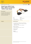
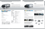
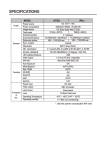
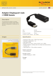
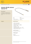
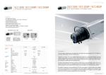
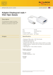
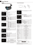
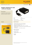
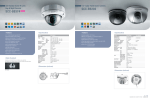
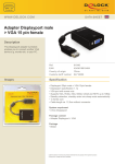
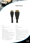
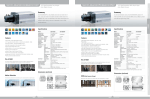
SCC-B2313/B2315
SCC-B2013P/B2015P
Specifications
7. DC IRIS Level Regulator
6. Function Switch-2
5. Function Switch-1
2. Power LED
3. Vertical Synchronization
Phase Control Switch (left)
1. Power Connection Terminal
8. Image Output Port
4. Vertical Synchronization
Phase Control Switch (right)
1. Power Connection Terminal : This is the terminal where a power (adaptor) cable is
3. Vertical Synchronization Phase Control Switch (left)
: Used when adjusting the vertical synchronization phase.
4. Vertical Synchronization Phase Control Switch (right)
: Used when adjusting the vertical synchronization phase.
5. Function Switch-1
· SW1(L/L) : If set to ‘OFF,’ the camera operates in internal
ON
1. L/L
2. ELC
3. FL
4. LSS
6. Function switch-2
ON
1/3" Super HAD CCD, 410K(PAL:470K) pixels
NTSC : 768(H)x494(V) / PAL : 752(H)x582(V)
2:1 Interlace
NTSC : 15.750Hz / PAL : 15.625Hz
NTSC : 60Hz / PAL : 50Hz
Internal / Line lock
540 TV Lines
VBS 1.0Vp-p(75 ohm, Composite)
50dB
0.0009(Sens up 128X,15IRE)Lux
Off/On
ATW/AWC
ALC(Video/DC) / ELC(~1/120Ksec)
Off/On
Off/On (V-Phase Regulation)
BNC
4-pin DIN
Terminal Block (2-pin)
-10°C ~ +50°C
Maximum 90% RH
AC24V / DC12V compatible
3W
440g
68(W) x 55(H) x 138(D)mm
Summary
The SCC-B2313/B2315 is a high resolution color camera equipped with
1/3" Super HAD Progressive scan CCD which delivers excellent Wide
Dynamic Range. It produces sharp images even in harsh lighting conditions that have large contrasts between lightness and darkness.
Specifications
* SCC-B2011P is same as SCC-B2311 except for Power Requirment (AC 220V~240V)
Dimensions (unit:mm)
1. AGC
2. DNR
3. D&N
4. AWB
SCC-B2311
Exterior
• 1/3" Super HAD Progressive CCD
• Day & Night (Moving filter)
• Horizontal resolution : 540(color)/570(B/W) TV Lines
• DNR (Digital Noise Reduction)
• Minimum scene illumination : 0.0005(color)/0.00005(B/W) Lux
• WDR (Wide Dynamic Range) - (SCC-B2313/B2013P is not available)
• 24ea Privacy Zones
• Motion Detection
• 2X D-Zoom
• OSD (On Screen Display)
• RS485 remote control
• AC24V / DC12V (B2013/B2015P : AC220V only)
1. Mount Adaptor
Installation Holes
SCC-B2011P
SCC-B2313/B2315
2. Auto Iris Lens
SCC-B2013P/B2015P
5. ALC Lens Selection
Switch
6. Control Cable for the
Auto Iris Lens
1/3" Super-HAD PS CCD, 410K(PAL:470K) pixles
NTSC : 768(H)x494(V) / PAL : 752(H)x582(V)
2:1 Interlace
NTSC : 15.750Hz / PAL : 15.625Hz
NTSC : 60Hz / PAL : 50Hz
Internal / Line lock (V PHASE control)
540 TV Lines
570 TV Lines
VBS 1.0Vp-p(75 ohm, composite)
50dB
C/CS Mount Compatible
0.0005(Sens up 256X,15IRE)Lux
0.00005(Sens up 256X,15IRE)Lux
Off/On(24EA)
DAY/NIGHT/AUTO/EXT
Off/On(4EA)
No
Yes
Off ~ 2X
Off ~ 1/10K sec
Off ~ 256X
Off/On(Area setting)
Off/Low/High
Off/On(Max.1/100K sec)
Off/On
Off/On
ATW1/ATW2/AWC/MANUAL
Yes
Yes(1EA)
RS485(Half)
-10°C ~ 50°C
Within 90% RH
AC24V / DC12V compatible
3.5W
410g
68(W) x 55(H) x 128.7(D)mm
* SCC-B2013P is same as SCC-B2313 except for Power Requirment (AC 220V~240V)
SCC-B2015P is same as SCC-B2315 except for Power Requirment (AC 220V~240V)
1. Mount Adaptor Installation Holes : When installing a camera to a bracket, these are
CONTROLLERS
used when fastening the mount adaptor to the
bracket with screws.
2. Auto Iris Lens (optional) : This is the lens that can be installed onto a camera.
3. Auto Iris Lens Connector : The power, control signal, video signal and DC signal needed
to control the lens iris are provided to the auto iris lens.
4. Flange Back Control Ring : This is used for controlling the back focus of camera.
5. ALC Lens Selection Switch : This is the switch for selecting the type of lens installed
onto the camera.
6. Control Cable for the Auto Iris Lens : This transmits the control signal sent by the
camera to control the lens iris.
18
NEW PRODUCTS_CAMERAS
SCC-B2315
NETWORK SECURITY
Dimensions (unit:mm)
4. Flange Back
Control Ring
3. Auto Iris Lens
Connector
SCC-B2313
Imaging Device
Effective Pixels
Scanning Method
Scanning
Horizontal
Line Frequency Vertical
Synchronization Method
Horizontal
Color
Resolution
B/W
Signal Output
S/N Ratio
S/N Ratio
Mount Type
Minimum Scene Color
Illumination
B/W
Functions
Privacy Zone
Day & Night
Motion Detection
Wide Dynamic Range
D-Zoom
High Speed Shutter
Sens Up
BLC
AGC
ELC
Line lock
Camera ID
White Balance
OSD
Alarm Output
Remote Control
Operating Temperature
Operating Humidity
Power Requirment
Power Consumption
Weight
Dimensions
DVRS
· SW1(AGC) : This switch is used to turn the camera AGC (Auto
Gain Control) ON/OFF.
· SW2(DNR) : This switch triggers the random noise reduction
function.
SW1 SW2 SW3 SW4
· SW3(D&N) : This refers to the Day & Night.
· SW4(AWB) : If this switch is set to ON, the screen color is automatically adjusted according
to the temperature change of the lighting color due to changes in the external
environment.
7. DC IRIS Level Regulator : When the ALC lens selection switch is set to DC, it regulates
the iris level by using a control lever.
8. Video Output Terminal : The video signal of the camera can be outputted through this
terminal to the video input terminal of a monitor.
Features
Model
MONITORS
synchronization mode and if set to ‘ON,’ it operates
in power synchronization mode.
SW1 SW2 SW3 SW4
· SW2(ELC) : If this switch, selected when using a manual iris
lens, is switched on, the electronic shutter speed is automatically controlled
according to screen brightness, in a range of 1/60~1/120,000 exposures
per second.
· SW3(FL) : This switch triggers the screen–flicker-prevention function in the 50Hz power
range, preventing the screen flicker that can result from the dissonance of
vertical synchronization frequency and blink frequency.
· SW4(LSS): This switch triggers the enhanced sensitivity mode, which eliminates image
noise by consistently accumulating image fields in the memory when images
are captured in a dark place, and by increasing the brightness and contrast ratio.
SCC-B2311
Imaging Device
Effective Pixels
Scanning Method
Scanning Line
Horizontal
Frequency
Vertical
Synchronization Method
Horizontal Resolution
Signal Output
S/N Ratio
Minimum Scene Illumination
Control Switch Day & Night
White Balance
ALC / ELC
Flickerless
Line lock
Input/Output
Image Output
AI Lens
Power
Operating Temperature
Operating Humidity
Power Requirment
Power Consumption
Weight
Dimensions
CAMERAS
connected.
Connect either AC24V or DC12V for power Requirment.
2. Power LED : The LED light is turned on if power is being supplied normally to the camera.
Model
NEW PRODUCTS
Rear
1/3" High Resolution WDR Color Camera
19
Video Security System
NEW PRODUCTS_CAMERAS
Video Security System