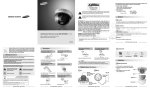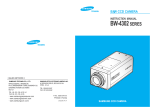
1
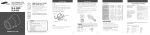
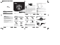
Thank you for purchasing a SAMSUNG CCD CAMERA.
Before operating the camera, confirm the camera model and proper input power voltage. In
order that you can understand this manual thoroughly, we'll introduce our model description.
The lightning flash with arrowhead symbol, within an equilateral triangle is intended to
alert the user to the presence of uninsulated "dangerous voltage" within the product's
enclosure that may be of sufficient magnitude to constitute a risk of electric shock to persons.
SID-50 SERIES
• NTSC models
SID-50N
• PAL models
SID-50P
Model Description
• SID-50X
• SIGNAL SYSTEM
N
P
Signal system
The exclamation point within an equilateral triangle is intended to alert the user to the
presence of important operating and maintenance (servicing) instructions in the literature
accompanying the appliance.
NTSC Model
PAL Model
FEATURES
INFORMATION-This equipment has been tested and found to comply with limits for a
Class A digital device, pursuant to part 15 of the FCC Rules. These limits are designed to
provide reasonable protection against harmful interference when the equipment is
operated in a commercial environment. This equipment generates, uses, and can radiate
radio frequency energy and, if not installed and used in accordance with the instruction
manual, may cause harmful interference to radio communications. Operation of this
equipment in a residential area is likely to cause harmful interference in which case the
user will required to correct the interference at his own expense.
SALES NETWORK
•
SAMSUNG TECHWIN CO., LTD.
145-3, Sangdaewon 1-dong, Jungwon-gu, Seongnam-si,
Gyeonggi-do 462-703, Korea
TEL : +82-31-740-8137~8141 FAX : +82-31-740-8145
•
SAMSUNG OPTO-ELECTRONICS UK, LTD.
Samsung House, 1000 Hillswood Drive, Hillswood
Business Park Chertsey, Surrey KT16 OPS
TEL : +44-1932-45-5308 FAX : +44-1932-45-5325
•
HIGH RESOLUTION MINI DOME CAMERA
INSTRUCTION MANUAL
TIANJIN SAMSUNG OPTO-ELECTRONICS CO., LTD.
7 Pingchang Rd, Nankai Dist. Tianjin 300190, P.R China
TEL : +86-22-2761-4724(33821) FAX : +86-22-2761-6514
www.samsungtechwin.com
www.samsungcctv.com
SID-50
P/No. : Z6806-0715-01A
VAN 06. 03
WARNING
The camera needs periodic inspection.
Contact an authorized technician for inspection.
WARNING -Changes or modifications not expressly approved by the manufacturer could
void the user’s authority to operate the equipment.
WARNING - To prevent electric shock and risk of fire hazards:
Do NOT use other than specified power source.
Do NOT expose this appliance to rain or moisture.
This installation should be made by a qualified service person and should conform to all local codes.
About this manual
Before installing and using the camera, please read this manual carefully. Be sure to keep it handy for later reference.
Do not install the camera in extreme
temperature conditions.
High Sensitivity
The built-in high sensitivity COLOR CCD enables a clear image even in 0.05Lux or lower illumination.
SSNR (Samsung Super Noise Reduction)
By using built-in SSNR function manufactured by SAMSUNG TECHWIN, the amount of low illuminance
noise has been significantly reduced, and the signal-to-noise ratio (S/N) as well as horizontal resolution
have been improved, resulting in a clear and sharp image display even in the dark.
Pan and Tilt
Pan and tilt are available after installing camera.
MINI DOME CAMERA 2 USER’S MANUAL
Do not touch the front glass of the
camera.
PRECAUTIONS
Horizontal Resolution 540 TV Lines
Clear image quility has been achieved by employing a CCD with 410,000 pixels(NTSC), 470,000
pixels(PAL) and optimized WINNER3 DSP CHIP which provides a horizontal resolution of 540 TV lines.
Never keep the camera face to strong
light directly.
Do not install or use the camera in an
environment where the humidity is high.
MINI DOME CAMERA 3 USER’S MANUAL
GETTING TO KNOW YOUR CAMERA
Front
Stop using your camera when you find a malfunction.
It is one of the most important parts of camera.
Be careful not to be stained by fingerprint.
If you use your camera around smoke or unusual heat for a long time, a fire
may be caused.
Do not Install the camera on a surface that can not support it.
Unless the surface is suitable, it could cause falling or other hazards.
Do not handle the camera with wet hands
Only use the camera under conditions where
temperatures are between -10˚C and +50˚C.
Be especially careful to provide ventilation
when operating under high temperatures.
Do not install the camera under
unstable lighting conditions.
It can damage the CCD.
It can cause the image quality to be poor.
Do not drop the camera or subject
them to physical shocks.
Do not expose the camera to rain or
spill beverage on it.
Never use the camera close to a gas
or oil leak.
Pan Base
You can rotate the lens
from 360˚
Tilt Base
You can adjust up and
down the camera(20°~90°).
Bottom
It could cause an electric shock.
It can cause malfunctions to occur.
If it gets wet, wipe it dry immediately.
Liquids can contain minerals that corrode the
electronic components.
Power Input Terminal
BNC Jack
Severe lighting change or flicker can cause
the camera to work improperly.
It can cause malfunctions to occur.
Notes
• If the camera is exposed to spotlight or object reflecting the strong light, smear or blooming may occur.
• Please check the power whether it satisfies the normal specification before connecting the camera.
Do not disassemble the camera.
There are no user-serviceable parts inside it.
MINI DOME CAMERA 4 USER’S MANUAL
MINI DOME CAMERA 5 USER’S MANUAL
MINI DOME CAMERA 6 USER’S MANUAL
MINI DOME CAMERA 7 USER’S MANUAL
Notes
For DC Power Type
Accessories
• When installing the camera on a ceiling or a wall, not to disturb adjustment of Tilt Base angle fix
the BNC-Power Cable on the Pan Base clip.
<Installing the camera on a ceiling>
BNC-Power Cable
M4 Taping Screw 2EA Cable Rubber
User Manual
Quick Install Guide
Pan Base clip
Template
#22(0.33mm2)
#20(0.52mm2)
#18(0.83mm2)
Resistance ( Ω / m)
0.078
0.050
0.030
0.018
Voltage Drop (V/m)
0.028
0.018
0.011
0.006
Copper wire size (AWG)
<Installing the camera on a wall>
Panning & Tilting Control
Resistance of copper wire [at 20C˚ (68˚F)]
#24(0.22mm2)
• As the voltage drop according to the length of the cable in the above table, a camera may
malfunction if there is an excessively long cable run.
* Voltage for camera operation: 12V DC ±10%
* Voltage drops in the above table are variable according to types of cable manufacturer.
INSTALLATION
Connection to Monitor
Installing Camera
1. Fix the camera to a ceiling or a wall using two screws.
2. After fixing it, adjust its pan base and
Hole
tilt base properly.
3. After adjusting them, secure the shield
case and dome-cover.
Screw
Connect the VIDEO-OUT jack to the VIDEO-IN jack of monitor.
Connection to Power
•Connect the adapter to the power input connector as shown in the figure below. Use a
DC12V 500mA. (The Adapter is not provided with the Dome Camera.)
•As a connecting method varies according to instruments, refer to the manual supplied with
the instrument.
•Connect the cable after power is turned off.
•Set the 75Ω / Hi-Z selection switch. If it is a intermediate device, switch it to Hi-z and if
it is final device, switch it to 75Ω. (Please refer to the Monitor Manual.)
DOME Camera
Adapter (not provided)
Intermediate
You can adjust up and down
the camera (20˚~90˚).
Tilt Base Holding
Screws
Pan Base
You can rotate the lens
from 360˚
Pan Base Holding Screw
1) Adjustment Panning angle: After attaching the dome camera to a ceiling or a wall, adjust the
panning angle for better monitoring area by rotating the Pan Base. The panning angle can be
adjusted 360˚ freely.
2) Adjustment Tilting angle: After attaching the dome camera to a ceiling or a wall, adjust
the tilting angle for better monitoring area by rotating the Tilt Base. The tilting angle can
be adjusted to 20˚ from 90˚ freely. (based the ceiling surface)
Notes
• After loosening Pan or Tilt Base holding screws, adjust its angle. And then tighten screws again.
• In case of adjusting the tilting, do not take the lens for preventing hysical shocks. Please take the Tilt Base.
• This dome camera is to be installed on the ceiling by factory default. In case of using camera on the wall,
readjust the Tilt angle as page 8 (Notes).
BNC
Shield Case
You can adjust the Panning and Tilting angle freely. (Panning angle: 360°,
Tilting angle: 20˚~90˚)
Tilt Base
Monitor
Dome Cover
Power Input Connector
MINI DOME CAMERA 8 USER’S MANUAL
CAMERA OPERATION
The SID-50 includes the following built in functions
Auto Functions
Setting Value
Electronic Shutter
Speed
ESC
The speed is controlled according to the
brightness of the screen.
ATW
It can be used within the color temperature
range 1,800K~10,500K(Ex fluorescent light,
outdoor, sodium vapor lamp or inside tunnels)
WHITE BALANCE
BACKLIGHT
MIDDLE
Descriptions
The gain increases within the range of
6dB~34dB
GAIN CONTROL
MIDDLE
The gain increases or decreases within the
range of 6dB~34dB
SSNR
(Noise Reduction)
LOW
There is sufficient reduction in noise levels
without causing much ghost imaging
SENS UP
ON
It helps maintain a bright, clear screen image by
automatically detecting changes in the level in
low light levels without causing much ghost
imaging.
SHARPNESS
ON
The outline of the video image becomes cleaner
and more distinctive as the level of
SHARPNESS increases.
DOME Camera
MINI DOME CAMERA 10 USER’S MANUAL
MINI DOME CAMERA 9 USER’S MANUAL
TROBLESHOOTING
DECLARATION OF CONFORMITY
SPECIFICATION
If you have trouble operating your camera, refer to the following. If the guidelines do not
enable you to solve the problem, contact an authorized technician.
DIMENSION
99.2
63.5
ITEM
SID-50N
Power Source
Total Pixels
CCD
Effective Pixels
SIZE
Scanning System
Sync.
Synchronization
Frequency
LENS(Built-in)
Resolution
E
Video Output
L
S/N(Y signal)
E
Min.Illumination
C
T
R
I
C
Auto Functions
A
L
The image on the screen is dim.
• Check if the lens are stained. If dirty, clean the lens with soft, clean cloth.
• The image is dimmer at night than daytime. If the focus is not right, adjust it at daytime.
The contrast on the screen is too weak.
• Adjust the contrast feature of the monitor.
• If the camera is exposed under too strong light, change the camera position.
• Adjust the lens BACK FOCUS again.
The camera is not work properly, and the surface of the camera case is hot.
• Check that you have connected the camera to a proper power (DC12V ).
99.2
67
99.2
1.2
R4
2-Ø 4.2
MINI DOME CAMERA 12 USER’S MANUAL
MINI DOME CAMERA 11 USER’S MANUAL
MINI DOME CAMERA 13 USER’S MANUAL
Monitoring
Pan
Angle
Tilt
Operating temperature/Humidity
Dimention
Weight
SID-50P
DC 12V±10%/Max. 1.8W
811(H) x 508(V)
768(H) x 494(V)
795(H) x 596(V)
752(H) x 582(V)
1/3 inch Super HAD CCD
2:1 Interlace
Internal Only
Horizontal:15.734 KHz/Vertical :59.94 Hz Horizontal: 15.625 KHz/Vertical : 50Hz
Built-in Fixed Lens 120 f=3.0mm, F2.0
540 TV Lines(Min.)
CVBS : 1.0Vp-p/75
50 dB (AGC Off,Weight ON)
0.05Lux/F1.2(Sens-up), 0.3Lux/F1.2
Electronic shutter speed
AUTO
WHITE BALANCE
AUTO
BACKLIGHT
AUTO
Gain Control
AUTO
SENS-UP
AUTO
SSNR(Noise Control)
AUTO
SHARPNESS
AUTO
Manual 360
Manual 20 ~ 90
-10˚C to +50˚C / 30% to 80% RH
99.2mm(W) x 99.2mm(H) x 67mm(D)
200g
MINI DOME CAMERA 14 USER’S MANUAL
Application of Council Directive(s)
Manufacturer's Name
Manufacturer's Address
European Representative Name
European Representative Address
Equipment Type/Environment
Model Name
Beginning Serial NO.
Year of Manufacture
Conformance to
89 / 336 / EEC
SAMSUNG TECHWIN CO., LTD
SAMSUNG TECHWIN CO., LTD
42, SUNGJU-DONG CHANGWON-CITY,
KYUNGNAM, KOREA, 641-120
MINI DOME CAMERA
SID-50
S6300001
2006. 03. 01
EN 50081-1 : 1992
EMC-Directive 89/336 EEC and 92/31/EEC
EN 50130-4 : 1996
We, the undersigned, hereby declare that the equipment specified above conforms to the above Directive(s).
Manufacturer
Signature
Full Name
Position
Place
Date
SAMSUNG TECHWIN CO., LTD
YOUNG TAEK SON
QUALITY CONTROL MANAGER
CHANGWON, KOREA
2006. 03. 01
Legal Representative in Europe
Signature
Full Name
Position
Place
Date
Correct Disposal of This Product
(Waste Electrical & Electronic Equipment)
(Applicable in the European Union and other European countries with separate collection systems)
This marking shown on the product or its literature, indicates that it should not be disposed with other household wastes at the
end of its working life. To prevent possible harm to the environment or human health from uncontrolled waste disposal, please
separate this from other types of wastes and recycle it responsibly to promote the sustainable reuse of material resources.
Household users should contact either the retailer where they purchased this product, or their local government office, for details
of where and how they can take this item for environmentally safe recycling.
Business users should contact their supplier and check the terms and conditions of the purchase contract. This product should not
be mixed with other commercial wastes for disposal.