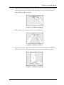
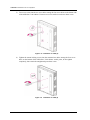
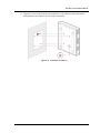
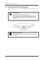
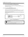
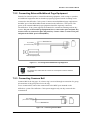
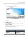
1
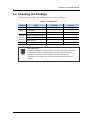
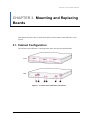
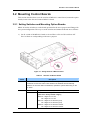
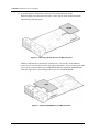
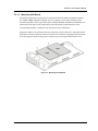
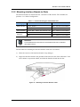
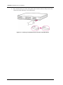
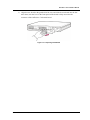
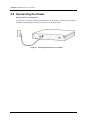
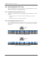
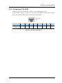
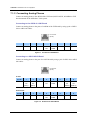
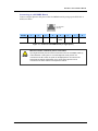
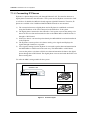
Ed.
00
OfficeServ 7100
Installation Manual
COPYRIGHT
This manual is proprietary to SAMSUNG Electronics Co., Ltd. and is protected by copyright.
No information contained herein may be copied, translated, transcribed or duplicated for any commercial
purposes or disclosed to the third party in any form without the prior written consent of SAMSUNG Electronics
Co., Ltd.
TRADEMARKS
is the trademark of SAMSUNG Electronics Co., Ltd.
Product names mentioned in this manual may be trademarks and/or registered trademarks of their respective
companies.
This manual should be read and used as a guideline for properly installing and operating the product.
This manual may be changed for the system improvement, standardization and other technical reasons without prior
notice.
If you need updated manuals or have any questions concerning the contents of the manuals, contact our Document
Center at the following address or Web site:
Address: Document Center 18th Floor IT Center. Dong-Suwon P.O. Box 105, 416, Maetan-3dong Yeongtong-gu,
Suwon-si, Gyeonggi-do, Korea 442-600
Homepage: http://www.samsungdocs.com
©2006 SAMSUNG Electronics Co., Ltd.
All rights reserved.
OfficeServ 7100 Installation Manual
INTRODUCTION
Purpose
OfficeServ 7100 is the most suitable system for offices using circuit lines with 10 to 25
subscribers. This manual describes the condition for OfficeServ 7100 system installation
and how to install, inspect and operate the system.
Document Content and Organization
This document consists of eight chapters, and abbreviations as follows:
CHAPTER 1. Before Installing
This chapter describes the checklists, such as the installation site and the grounding & the
power conditions, to be inspected before installing the OfficeServ 7100 system.
This chapter also describes the items included in the OfficeServ 7100 package and the
installation procedure.
CHAPTER 2. Installing Cabinets
This chapter describes how to install an OfficeServ 7100 cabinet on the ground or inside a
rack, depending on the installation environment, and how to connect the grounding wire.
CHAPTER 3. Mounting and Replacing Boards
This chapter describes how to mount or replace various boards of the OfficeServ 7100
system.
CHAPTER 4. Connecting External Batteries
This chapter describes how to connect an external battery to the OfficeServ 7100 system.
CHAPTER 5. Connecting the Power
This chapter describes how to connect the power to the OfficeServ 7100 system.
CHAPTER 6. Connecting C.O. Lines
This chapter describes how to connect C.O. lines to the OfficeServ 7100 system.
© SAMSUNG Electronics Co., Ltd.
I
Ошибка! Стиль не определен.
CHAPTER 7. Connecting Stations and Additional Equipment
This chapter describes how to connect various stations and additional equipment, such as
analog/digital phones, door phones and door locks, to the OfficeServ 7100 system.
CHAPTER 8. Starting the System
This chapter describes items to check before starting the OfficeServ 7100 system, the procedure
for starting the system, and the procedure for testing whether the system is normally operating
after startup.
ABBREVIATION
Abbreviations frequently used in this document are described.
Conventions
The following types of paragraphs contain special information that must be carefully read
and thoroughly understood. Such information may or may not be enclosed in a rectangular
box, separating it from the main text, but is always preceded by an icon and/or a bold title.
WARNING
Provides information or instructions that the reader should follow in order to avoid
personal injury or fatality.
CAUTION
Provides information or instructions that the reader should follow in order to avoid
a service failure or damage to the system.
CHECKPOINT
Provides the operator with checkpoints for stable system operation.
NOTE
Indicates additional information as a reference.
II
© SAMSUNG Electronics Co., Ltd.
OfficeServ 7100 Installation Manual
Reference
OfficeServ 7100 System Manual
This document introduces OfficeServ 7100 and describes the system information, such as
hard configuration, specification, and functions, necessary for this system.
OfficeServ 7100 Programming Manual
This document describes how to use the MMC program to change the OfficeServ 7100
system setting by using a phone.
Revision History
EDITION
DATE OF ISSUE
REMARKS
00
08. 2006.
Original Draft
01
01.2007.
Safety, VM and Router etc.
02
04.2007.
DoC, 2BRM Modular Jack Connection
© SAMSUNG Electronics Co., Ltd.
III
Ошибка! Стиль не определен.
This page is intentionally left blank.
IV
© SAMSUNG Electronics Co., Ltd.
OfficeServ 7100 Installation Manual
SAFETY CONCERNS
For product safety and correct operation, the following information must be given to the
operator/user and shall be read before the installation and operation.
Symbols
Caution
Indication of a general caution
Restriction
Indication for prohibiting an action for a product
Instruction
Indication for commanding a specifically required action
© SAMSUNG Electronics Co., Ltd.
V
Ошибка! Стиль не определен.
Warning
WARNING
Caution for Grounding
- Do not connect the grounding wire of the OfficeServ 7100 system to a power
conduit of a building
- The standards for power and grounding should comply with the country standard
and the pertinent work should be conducted according to the country standard.
- External grounding is required to prevent human injuries or system damages
caused by lightning, static electricity, or voltage surge.
- Unplug the AC power cord before connecting the grounding wire. Failure to do
so may cause human injury.
- The OfficeServ 7100 system should be connected to an outlet with a protective
ground.
- The GND in the back panel of the OfficeServ 7100 system should be grounded.
Use of Double-pole/neutral fusing
If the system is repaired after removing only one fuse used in the neutral line,
it may cause electric shock. If the repair is required, repair the system after
extracting the plug of the power cord.
Caution for powers when mounting boards
Check if the cabinet power is off when mounting boards on slots. Inserting or
ejecting a board while the power is on may damage the board.
Caution for the connection of the ground cable
Unplug the AC power cord before connecting the ground cable. If the connection
work is performed when the power cable is connected, it may cause serious
bodily damage.
VI
© SAMSUNG Electronics Co., Ltd.
OfficeServ 7100 Installation Manual
Caution
CAUTION
Caution for Installation
Only a trained service staff can install the OfficeServ 7100 system.
The equipment intended only for installation in a RESTRICTED ACCESS
LOCATION
Caution for the connection of External Batteries
Do not connect an external AC power until the battery and the system is
completely disconnected. To do so may cause electric shock to the constructor or
the system.
Make sure that the specified polarities(+, -) are correctly connected when
connecting external batteries.
To reduce risk of fire and injury to persons, use only a sealed nickel cadmium or
lead-acid battery supply capable of handling a charge current of 0.25 A, a charge
voltage of -54 V dc and a discharge rate of 26 Ah.
Leakage currents due to ringing voltage – Earthing installation instructions
1. A supplementary equipment earthing conductor is to be installed between the
product or system and earth, that is, in addition to the equipment earthing conductor
in the power supply cord.
2. The supplementary equipment earthing conductor may not be smaller in size than
the unearthed branch-circuit supply conductors. The supplementary equipment
earthing conductor is to be connected to the product at the terminal provided, and
connected to earth in a manner that will retain the earth connection when the power
supply cord is unplugged. The connection to earth of the supplementary earthing
conductor shall be in compliance with the appropriate rules for terminating bonding
jumpers in Part K of Article 250 of the National Electrical Code, ANSI/NFPA 70 and
Article 10 of Part 1 of the Canadian Electrical Code, Part 1, C22.1. Termination of
the
supplementary earthing conductor is permitted to be made to building steel, to a
metal electrical raceway system, or to any earthed item that is permanently and
reliably connected to the electrical service equipment earthed.
3. Bare, covered, or insulated earthing conductors are acceptable. A covered or
insulated conductor must have a continuous outer finish that is either green, or
green with one or more yellow stripes.
© SAMSUNG Electronics Co., Ltd.
VII
Ошибка! Стиль не определен.
Separation of TNV and SELV - Pluggable A
The separate protective earthing terminal provided on this product shall be
permanently connected to earth. (Instruction)
Telephone line cord
To reduce the risk of fire, use only No. 26 AWG or larger (e.g., 24 AWG) UL Listed
or CSA Certified Telecommunication Line Cord.
Safety Instructions for Rack Mount
The following or similar rack-mount instructions are included with the installation
instructions:
- Elevated Operating Ambient If installed in a closed or multi-unit rack assembly,
the operating ambient temperature of the rack environment may be greater than
room ambient. Therefore, consideration should be given to installing the
equipment in an environment compatible with the maximum ambient temperature
(Tma) specified by the manufacturer.
- Reduced Air Flow: Installation of the equipment in a rack should be such that the
amount of air flow required for safe operation of the equipment is not
compromised.
- Mechanical Loading: Mounting of the equipment in the rack should be such that
a hazardous condition is not achieved due to uneven mechanical loading.
- Circuit Overloading: Consideration should be given to the connection of the
equipment to the supply circuit and the effect that overloading of the circuits might
have on over-current protection and supply wiring. Appropriate consideration of
equipment nameplate ratings should be used when addressing this concern.
- Reliable Earthing: Reliable earthing of rack-mounted equipment should be
maintained. Particular attention should be given to supply connections other than
direct connections to the branch circuit (e.g. use of power strips)."
Prohibition of Metal Accessories
Do not wear metal accessories such as rings and watches to prevent electric
damages to the system.
VIII
© SAMSUNG Electronics Co., Ltd.
OfficeServ 7100 Installation Manual
Un-allowed Use of Selector Switch
The OfficeServ 7100 system only use 230 V. Do not change the input power
freely by means of the selector switch.
AC Power Connection Inhibited
Do not operate other devices with the AC power of the OfficeServ 7100 system or
with the DC power of external batteries.
Check of Power-off
Check if the cabinet power is off when mounting boards on slots. Inserting or
ejecting a board while the power is on may damage the board.
Board Reset
New settings are applied only after the board is reset. The system may
malfunction if the board is not properly initialized.
Caution for Installation
Only a trained service staff can install the OfficeServ 7100 system.
© SAMSUNG Electronics Co., Ltd.
IX
Ошибка! Стиль не определен.
This page is intentionally left blank.
X
© SAMSUNG Electronics Co., Ltd.
OfficeServ 7100 Installation Manual
TABLE OF CONTENTS
INTRODUCTION
I
Purpose ................................................................................................................................................. I
Document Content and Organization..................................................................................................... I
Conventions........................................................................................................................................... II
Reference ............................................................................................................................................. III
Revision History.................................................................................................................................... III
SAFETY CONCERNS
IV
Symbols ................................................................................................................................................IV
Warning.................................................................................................................................................IV
Caution .................................................................................................................................................IV
CHAPTER 1. Before Installing
1.1
1-4
Site Information ..................................................................................................................... 1-4
1.1.1
Safety Conditions .................................................................................................................. 1-4
1.1.2
Temperature and Humidity.................................................................................................... 1-4
1.2
Grounding Conditions .......................................................................................................... 1-4
1.3
Power Conditions .................................................................................................................. 1-4
1.4
Checking the Package .......................................................................................................... 1-4
CHAPTER 2. Installing Cabinets
2-4
2.1
Procedure for the System Installation ................................................................................. 2-4
2.2
Selecting Installation Method ............................................................................................... 2-4
2.3
Installing in a Rack ................................................................................................................ 2-4
2.4
2.3.1
Cautions for Installation......................................................................................................... 2-4
2.3.2
Tools Required ...................................................................................................................... 2-4
2.3.3
Installing in a Rack ................................................................................................................ 2-4
Installing on a Wall ................................................................................................................ 2-4
2.4.1
Tools Required ...................................................................................................................... 2-4
2.4.2
Installing on a Wall ................................................................................................................ 2-4
© SAMSUNG Electronics Co., Ltd.
XI
Ошибка! Стиль не определен.
2.5
Connecting the Grounding Wire ...........................................................................................2-4
CHAPTER 3. Mounting and Replacing Boards
3-4
3.1
Cabinet Configuration ...........................................................................................................3-4
3.2
Mounting Control Boards ......................................................................................................3-4
3.3
3.2.1
Setting Switches and Mounting Option Boards. ...................................................................3-4
3.2.2
Mounting Control Boards ......................................................................................................3-4
Mounting Interface Boards....................................................................................................3-4
3.3.1
Setting Switches and Mounting Optional Boards .................................................................3-4
3.3.2
Mounting Interface Boards to Slots.......................................................................................3-4
3.4
Connecting Power Fail Transfer ...........................................................................................3-4
3.5
Replacing Boards...................................................................................................................3-4
CHAPTER 4. Connecting External Batteries
4-4
4.1
Cautions for Connecting External Batteries ........................................................................4-4
4.2
Connecting External Batteries ..............................................................................................4-4
CHAPTER 5. Connecting the Power
5-4
5.1
Cautions when Connecting Power .......................................................................................5-4
5.2
Connecting the Power ...........................................................................................................5-4
CHAPTER 6. Connecting C.O. Line
6-4
6.1
Line Conditions ......................................................................................................................6-4
6.2
Connecting the C.O. Line ......................................................................................................6-4
6.2.1
Cautions to Connect the C.O. Line .......................................................................................6-4
6.2.2
Connecting Common C.O. Line............................................................................................6-4
6.2.3
Connecting T1/E1/PRI ..........................................................................................................6-4
CHAPTER 7. Connecting Stations and Additional Equipment
7.1
XII
7-4
Connecting Stations ..............................................................................................................7-4
7.1.1
Cautions for Connecting Stations..........................................................................................7-4
7.1.2
Connecting Analog Phones...................................................................................................7-4
7.1.3
Connecting Digital Phones....................................................................................................7-4
7.1.4
Connecting IP Phones ..........................................................................................................7-4
7.1.5
Connecting to a Door Phone and a Door Lock.....................................................................7-4
© SAMSUNG Electronics Co., Ltd.
OfficeServ 7100 Installation Manual
7.2
Connecting Additional Equipment ....................................................................................... 7-4
7.2.1
Connecting MOH/BGM Equipment ...................................................................................... 7-4
7.2.2
Connecting External/Additional Page Equipment................................................................. 7-4
7.2.3
Connecting Common Bell ..................................................................................................... 7-4
7.2.4
Changing System Setting ..................................................................................................... 7-4
7.2.5
Connecting SMDR ................................................................................................................7-4
7.2.6
Connecting Printers............................................................................................................... 7-4
CHAPTER 8. Starting the System
8.1
8-4
Pre-Check............................................................................................................................... 8-4
8.1.1
Environment .......................................................................................................................... 8-4
8.1.2
Safety Conditions .................................................................................................................. 8-4
8.2
Starting the System ............................................................................................................... 8-4
8.3
Numbering Extensions and C.O. Lines ............................................................................... 8-4
8.4
Checking System Operation................................................................................................. 8-4
8.4.1
Station Call Function ............................................................................................................. 8-4
8.4.2
Station Camp-On Function.................................................................................................... 8-4
8.4.3
C.O. Line Call Function ......................................................................................................... 8-4
8.4.4
C.O. Line Camp-On Function ............................................................................................... 8-4
ABBREVIATION
IV
4 ~ I.......................................................................................................................................................IV
K ~ W....................................................................................................................................................IV
© SAMSUNG Electronics Co., Ltd.
XIII
Ошибка! Стиль не определен.
LIST OF FIGURES
Figure 2.1 Tools for the Installation inside a Rack...................................................................2-4
Figure 2.2
Rack Installation (1) ...............................................................................................2-4
Figure 2.3
Rack Installation (2) ...............................................................................................2-4
Figure 2.4
Rack Installation (3) ...............................................................................................2-4
Figure 2.5
Required Tools for the installation on a Wall ..........................................................2-4
Figure 2.6 Installation on a Wall (1).........................................................................................2-4
Figure 2.7 Installation on a Wall (2).........................................................................................2-4
Figure 2.8 Installation on a Wall (3).........................................................................................2-4
Figure 2.9 Installation on a Wall (4).........................................................................................2-4
Figure 2.10 Installation on a Wall (5).......................................................................................2-4
Figure 2.11 Installation on a Wall (6) .......................................................................................2-4
Figure 2.12 Installation on a Wall (7)......................................................................................2-4
Figure 2.13
Grounding ............................................................................................................2-4
Figure 3.1
Front/rear View of OfficeServ 7100 Cabinet...........................................................3-4
Figure 3.2 Setting Switches of MP10/11 Board.......................................................................3-4
Figure 3.3 Mounting a Modem Board on the MP10/11 Board .................................................3-4
Figure 3.4 Mounting 4SWM/4DLM on the MP10/11 Board .....................................................3-4
Figure 3.5 Mounting the Control Board to Slot 0 .....................................................................3-4
Figure 3.6 Inserting the Control Board to a connector of the Main Board ...............................3-4
Figure 3.7 Mounting the UNI Board ........................................................................................3-4
Figure 3.8 Setting the Switch of the TEPRI Board ..................................................................3-4
Figure 3.9 Setting Switches of the TEPRI2 Board ..................................................................3-4
Figure 3.10
PLIM Board ..........................................................................................................3-4
Figure 3.11 Mounting an Interface Board on a Slot .................................................................3-4
Figure 3.12 Inserting a control Board to the Connector of the Main Board .............................3-4
Figure 3.13 Connecting Power Fail Transfer to a 16SLI2/8SLI Board.....................................3-4
Figure 3.14 Turning the Cabinet Power Off.............................................................................3-4
Figure 3.15 Removing a Board ...............................................................................................3-4
Figure 3.16 Replacing a New Board .......................................................................................3-4
XIV
Figure 4.1
Connecting an External Battery...........................................................................4-4
Figure 5.1
Connecting the Power (use of a cabinet) ...............................................................5-4
Figure 6.1
RJ-45 Port of 4TRM//8TRK Board .........................................................................6-4
Figure 6.2
RJ-45 Port(T-Mode only) of 2BRM Board ..............................................................6-4
© SAMSUNG Electronics Co., Ltd.
OfficeServ 7100 Installation Manual
Figure 6.3
RJ-45 Port of TEPRI Board ................................................................................... 6-4
Figure 7.1
RJ-45 Port of 4SLM Board .................................................................................... 7-4
Figure 7.2
RJ-45 Port of 16SLI2 Board .................................................................................. 7-4
Figure 7.3
RJ-45 Port of 8COMBO Board (for Analog Phone Connection) ............................ 7-4
Figure 7.4
RJ-45 Port of 4DLM Board .................................................................................... 7-4
Figure 7.5
RJ-45 Port of a 8DLI (for a digital phone) .............................................................. 7-4
Figure 7.6
RJ-45 Port of 8COMBO Board (for digital phone) ................................................. 7-4
Figure 7.7 IP Phone Layout.................................................................................................... 7-4
Figure 7.8
RJ-45 Port of Ethernet Connection Board ............................................................. 7-4
Figure 7.9
RJ-45 Port of 8DLI/16DLI2/8COMBO/4DLM Boards (for Door Phone) ................. 7-4
Figure 7.10 Connecting MOH/BGM Sources ......................................................................... 7-4
Figure 7.11 Connecting External/Additional Page Equipment ................................................ 7-4
Figure 7.12 Connecting Common Bells.................................................................................. 7-4
Figure 7.13
WebMMC Initial Screen....................................................................................... 7-4
Figure 7.14 Connecting SMDR............................................................................................... 7-4
Figure 7.15 Connecting Printers............................................................................................. 7-4
LIST OF TABLES
Table 1.1 Power Standards..................................................................................................... 1-4
Table 1.2 Package Items ........................................................................................................ 1-4
Table 3.1 Mountable Boards on Slots ..................................................................................... 3-4
Table 3.2 Parts on the Rear Panel of the Cabinet .................................................................. 3-4
Table 3.3 Switches of MP10/11 Board .................................................................................... 3-4
Table 3.4 Control Board Types ............................................................................................... 3-4
Table 3.5 Interface Board for Switche/Jumper Setting............................................................ 3-4
Table 3.6 Interface Boards that can mount option boards ...................................................... 3-4
Table 3.7 Interface Board Types and Available Slots.............................................................. 3-4
Table 6.1 Line condition of OfficeServ 7100 ........................................................................... 6-4
Table 7.1 Distance Between Stations and the System ........................................................... 7-4
Table 7.2 Specification of the SMDR System ......................................................................... 7-4
© SAMSUNG Electronics Co., Ltd.
XV
Ошибка! Стиль не определен.
This page is intentionally left blank.
XVI
© SAMSUNG Electronics Co., Ltd.
OfficeServ 7100 Installation Manual
CHAPTER 1. Before Installing
This chapter describes items to check when inspecting the installation site and the
grounding and power conditions before installing the OfficeServ 7100 system. This chapter
also describes the items included in the OfficeServ 7100 package and the installation
procedure.
1.1 Site Information
Select a site that satisfies the following conditions for safety, temperature and humidity:
1.1.1 Safety Conditions
y
The OfficeServ 7100 system should not be installed near materials that can cause a fire,
such as explosive gas and inflammables.
y
The OfficeServ 7100 system should not be near equipments that generate
electromagnetic waves, such as monitors or copying machines.
y
The installation location should be convenient for distributing trunk lines and
extension lines, for connecting power and grounding wires, and for maintenance and
repair.
y
The OfficeServ 7100 system should not be installed in aisles or passageways that are
populated or used for moving equipment.
y
Always maintain cleanliness to prevent dust from damaging the board-connecting part
of the cabinet.
y
Before installing the OfficeServ 7100 system, check items such as the electric wiring
status, grounding status, voltage and frequency.
1.1.2 Temperature and Humidity
y
The conditions for temperature and humidity are as follows:
− Operation Temperature: 0~40°C
− Storage temperature: -10~50°C
− Humidity: 10~90%
y
Cool area without direct sunlight
y
Ventilators should be installed to remove dust.
© SAMSUNG Electronics Co., Ltd.
1-1
CHAPTER 1. Ошибка! Стиль не определен.
1.2 Grounding Conditions
y
The following cautions should be taken when grounding the OfficeServ 7100 system:
y
The grounding wire of the OfficeServ 7100 system should be grounded to the earth
using a proper material.
y
The flow of electric current between the grounding wire of the power plug and the
exposed metal surface of the system should be satisfactory.
y
When connecting grounding of external additional equipments to the grounding of the
system, the groundings should be connected through a single connection point.
Cautions for Grounding
- Do not connect the grounding wire of the OfficeServ 7100 system to a power
conduit of a building.
- The standards for power and grounding should comply with the country
standard and the pertinent work should be conducted according to the country
standard.
- External grounding is required to prevent human injuries or system damages
caused by lightning, static electricity, or voltage surge.
- Unplug the AC power code before connecting the ground line. Failure to do so
may cause bodily damage.
- OfficeServ 7100 System should be connected to an outlet with a protective
ground.
- The GND in the back of the OfficeServ 7100 system should be grounded.
1.3 Power Conditions
The power supply board of the OfficeServ 7100 system receives AC input power or battery
power, and supplies -54 V, -5 V, +5 V, +3.3 V, +12 V, and -54 V(Battery) to the system
cabinet.
The power condition is as follows:
y
AC 220-240V, 1.5 A, 50/60 Hz, or DC 48 V, 3 A
Table 1.1 Power Standards
Power Supply
Standards
Power Supply
Input Power
AC 230 V
Unit(PSU)
Output
- DC -54 V, 1.1 A
Power
- DC +5 V, 5 A
- DC -5.3 V, 0.3 A
- DC +3.3 V, 5 A
- DC +12 V, 0.4 A
- DC -54 V, 0.25 A(for backup)
1-2
© SAMSUNG Electronics Co., Ltd.
OfficeServ 7100 Installation Manual
1.4 Checking the Package
The list of items included in the OfficeServ 7100 package is as follows:
Table 1.2 Package Items
Category
Name
Quantity
Remark
Cabinet
Basic Cabinet
1
-
Cable
Power Cable
1
-
Battery Cable
1
-
Items for
Bracket for attaching Cabinet
1
19” Rack
Screws for attaching Cabinet
3
Other Screws
2
Blank stiffener
1
Installation
Others
UTP Cable Types
Available UTP cables are Straight-through UTP cable and Crossover UTP cable.
The Straight-through UTP cable is used for connecting LIM module of the
OfficeServ 7100 system to other modules such as MP10/11 and MGI.
The Crossover UTP cable is only used for the connection between the LIM
modules.
© SAMSUNG Electronics Co., Ltd.
1-3
CHAPTER 1. Ошибка! Стиль не определен.
This page is intentionally left blank.
1-4
© SAMSUNG Electronics Co., Ltd.
OfficeServ 7100 Installation Manual
CHAPTER 2. Installing Cabinets
This chapter describes how to install an OfficeServ 7100 cabinet on the ground, inside rack
or on a wall depending on the installation environment.
2.1 Procedure for the System Installation
The procedure of system installation is as follows:
1)
2)
3)
4)
5)
6)
Install the cabinet on the ground, inside rack or on a wall depending on the installation
environment.
Ground to the ground lug behind the basic cabinet.
Insert the MP10/11 board into the slot 0 of the basic cabinet.
Insert various interface boards into the universal slots(slot 1 and slot 2).
Connect an external battery.
Connect input power of AC 230 V..
2.2 Selecting Installation Method
The OfficeServ 7100 cabinet can be installed on the ground, inside a 19-inch rack or on a
wall depending on the number of cabinets and environment of the installation area.
© SAMSUNG Electronics Co., Ltd.
2-1
CHAPTER 2. Ошибка! Стиль не определен.
2.3 Installing in a Rack
This section describes how to install the OfficeServ 7100 cabinet inside a 19-inch rack.
2.3.1 Cautions for Installation
Take the following cautions when installing the OfficeServ 7100 cabinet inside a rack:
y
The 19” rack should be a standard electric equipment rack.
y
When using an enclosed-type rack, check if the rack is properly ventilated. Vents
should be equipped on the side of the rack and fans should be attached to ventilate
cool air into the rack.
y
For the enclosed-type rack that the fan is attached on the top, beware that the hot-air
generated in the system on the bottom part can go up and enters to the inlet port of the
installed system.
y
When using an open rack, do not block the entrance of a port or fan of the OfficeServ
7100 system.
2.3.2 Tools Required
y
A middle-sized Phillips screwdriver
y
Two brackets and six screws for
attaching rack
y
Two clamp screws
Figure 2.1 Tools for the Installation inside a Rack
2.3.3 Installing in a Rack
The procedure for installing the OfficeServ 7100 cabinet inside a 19-inch rack is as
follows:
1)
Attach the cabinet bracket to the bottom surface of the OfficeServ 7100 cabinet and
fasten the bracket firmly with the two screws.
Figure 2.2 Rack Installation (1)
2-2
© SAMSUNG Electronics Co., Ltd.
OfficeServ 7100 Installation Manual
2)
Slide the cabinet attaching the bracket in Step 1.
Figure 2.3 Rack Installation (2)
3)
Align the two holes of the cabinet bracket and the holes of the rack brackets, and
fasten the cabinet to the rack with the two screws.
Figure 2.4 Rack Installation (3)
© SAMSUNG Electronics Co., Ltd.
2-3
CHAPTER 2. Ошибка! Стиль не определен.
2.4 Installing on a Wall
This section describes how to install the OfficeServ 7100 cabinet on a wall.
2.4.1 Tools Required
y
Mid-sized Phillips screw driver
y
Electric drill
y
Hammer
y
Wall-type bracket
y
Four plastic anchors
y
Four cross-type screws
y
Four Mount locking screws
Figure 2.5 Required Tools for the installation on a Wall
2.4.2 Installing on a Wall
The way to install the OfficeServ 7100 cabinet by using a wall-type bracket is as follows:
1)
There are four holes for the screws on the top/bottom of the bracket(A positions of the
figure below). Mark four holes on a desired wall by using the bracket.
A
A
Figure 2.6 Installation on a Wall (1)
2-4
© SAMSUNG Electronics Co., Ltd.
OfficeServ 7100 Installation Manual
2)
Make holes on the marked position of the wall-type bracket. Make the depths and the
diameters of the holes more than 35 mm and around 5.5 mm to enable to insert the
plastic anchors easily, respectively.
Figure 2.7 Installation on a Wall (2)
3)
With a hammer, drive plastic anchors into the drilled holes.
Figure 2.8 Installation on a Wall (3)
4) Align the screw holes of the wall-type bracket to the position that the plastic anchors are
driven. Insert screws to each hole and tighten the screws with a philips screw driver.
Figure 2.9 Installation on a Wall (4)
© SAMSUNG Electronics Co., Ltd.
2-5
CHAPTER 2. Ошибка! Стиль не определен.
5)
Two screws exists into the two screw holes among the four screw holes on the bottom side
of the OfficeServ 7100 cabinet. Unscrew two screws with a screw driver about 2 mm.
2 mm
Figure 2.10 Installation on a Wall (5)
6)
Tighten the mount locking screws into the remained two holes among the four screw
holes on the bottom of the OfficeServ 7100 cabinet. At this point, do not tighten
completely, but remain the untightened part about 2 mm.
Figure 2.11 Installation on a Wall (6)
2-6
© SAMSUNG Electronics Co., Ltd.
OfficeServ 7100 Installation Manual
7)
Align the screws on the bottom of the OfficeServ 7100 cabinet to the bracket holes,
then pull down the cabinet to fix the cabinet completely.
2 mm
Figure 2.12 Installation on a Wall (7)
© SAMSUNG Electronics Co., Ltd.
2-7
CHAPTER 2. Ошибка! Стиль не определен.
2.5 Connecting the Grounding Wire
This section describes how to connect an external grounding wire to the OfficeServ 7100
system.
External Grounding
External grounding is required to prevent human injuries or system damages
caused by lightning, static electricity, or voltage surge.
The OiiceServ 7100 system has to be grounded by big electric wire more
than a cross-sectional area is 4.0mm2. The Screw should be minimum 3.5
mm nominal thread diameter and Ring Terminal should be UL Listed Lug
Terminal used.
As shown in the figure below, ground to the ground lug behind the OfficeServ 7100.
Figure 2.13 Grounding
Checking external grounding
After installing the OfficeServ 7100 system, make sure that the GND in the back
side of the system cabinet is connected to the external ground for communication
before the operation.
2-8
© SAMSUNG Electronics Co., Ltd.
OfficeServ 7100 Installation Manual
CHAPTER 3. Mounting and Replacing
Boards
This chapter describes how to mount and replace various boards of the OfficeServ 7100
system.
3.1 Cabinet Configuration
The cabinet of the OfficeServ 7100 System has three slots that can install boards.
Front
Slot 0
Slot 1
Slot 2
Rear
Figure 3.1 Front/rear View of OfficeServ 7100 Cabinet
© SAMSUNG Electronics Co., Ltd.
3-1
CHAPTER 3. Ошибка! Стиль не определен.
Following boards are mounted on the slots according to the configuration of the OfficeServ
7100.
Table 3.1 Mountable Boards on Slots
Cabinet
Slot
Control Part
Slot 0
Subscriber
Slot 1 and Slot 2
Mountable Board
MP10, MP11
- OS 7100 Card: UNI board
- OS 7200 Card: 8/16DLI2, 8/16SLI2, 8COMBO, 8TRK,
Part
TEPRI, LIM, MGI,
(UNI)
- OS7400 Card: TEPRI2, MGI64
The descriptions about each part on the rear of the cabinet are listed in the table below.
Table 3.2 Parts on the Rear Panel of the Cabinet
Part
3-2
Function
Power Switch
Power on/off the OfficeServ 7100 system.
Power I/O Switch
Connector for the power cable connection
AC LED
The LED indicates the input of AC power.
DC LED
The LED indicates the normal output of DC power.
Battery Socket
Socket to connect an external battery
Ground Lug
Lug for the ground of the system communication
© SAMSUNG Electronics Co., Ltd.
OfficeServ 7100 Installation Manual
3.2 Mounting Control Boards
This section describes how to set the switches of MP10/11 control board, mount the option
boards, insert to the slots and connect MP10/11 board.
3.2.1 Setting Switches and Mounting Option Boards.
MP10/11 has the switches to set the board operation for the user’s purpose and fitting with
the system configuration. The way to set the switches and mount the boards are as follows:
1)
Set S1 switch of the MP10/11 board as On and Pin 1 to Pin 4 of S2 switch as Off.
Pin 6 to Pin 8 are set depending on the user’s purpose.
S2
On
Off
S1
Off
On
Figure 3.2 Setting Switches of MP10/11 Board
Table 3.3 Switches of MP10/11 Board
Switch
S1
Description
Set S1 as On before mounting on the slot for memory backup.
If switched On when the switch is Off. all data in the database are automatically
initialized. To store the data in the database, operate the system after turning on the
S1 switch.
S2
SW1~SW4
the pins are set the country code that the system will be used.
SW6~SW8
Sets the number of digits for C.O./extension lines and extension.
[ Not-used : Always default 3 digits ]
SW6-On: 4 digits for C.O. line
Off: 3 digits for C.O. line
SW7-On: 4 digits for an extension group
Off: 3 digits for an extension group
SW8-On: 4 digits for an extension number
Off: 3 digits for an extension number
© SAMSUNG Electronics Co., Ltd.
3-3
CHAPTER 3. Ошибка! Стиль не определен.
2)
A modem board is mounted to connector P7/P8 of the MP10/11 board.
When mounting a modem board, the holes on the corners of the modem should be
aligned fitting with the spacer.
MODEM
Figure 3.3 Mounting a Modem Board on the MP10/11 Board
4SWM or 4DLM can be mounted to connector P11, P12 and P13 of the MP10/11
board. Screws are basically locked to the support beside P13. Unscrew and position the
screws to the connector direction of 4SWM/4DLM before mounting 4SWM/4DLM.
After that, tighten the screws fitting with the grooves of 4SWM/4DLM.
4SWM
Figure 3.4 Mounting 4SWM/4DLM on the MP10/11 Board
3-4
© SAMSUNG Electronics Co., Ltd.
OfficeServ 7100 Installation Manual
3.2.2 Mounting Control Boards
Mount a control board to the slot 0 of the OfficeServ 7100 cabinet. For the locations of slot
0 to slot 2, refer to ‘3.1. Cabinet Configuration’.
Table 3.4 Control Board Types
Control Board
Mountable Slot
MP10/11
Slot 0 of the Basic Cabinet
Mount the MP10/11 board as follows:
1)
Check if the MP10/11 board to be mounted is damaged.
Caution for the power when mounting boards
Check if the cabinet power is off when mounting boards on slots. Inserting or
ejecting a board while the power is on may damage the board or cause fire.
2)
Align the MP10/11 board to the guardrail of slot 0 of the basic cabinet, and slide the
board into the slot with care.
Figure 3.5 Mounting the Control Board to Slot 0
3)
Press and lock the lever on the front panel of the MP10/11 board to fully insert to the
connector of the OfficeServ 7100 connector.
Figure 3.6 Inserting the Control Board to a connector of the Main Board
© SAMSUNG Electronics Co., Ltd.
3-5
CHAPTER 3. Ошибка! Стиль не определен.
3.3 Mounting Interface Boards
This section describes how to set jumpers and switches of an interface board, how to mount
optional boards to an interface board, and how to mount interface boards into slots.
3.3.1 Setting Switches and Mounting Optional Boards
These interface boards are divided into the boards to set switches or jumpers and the boards
to mount option boards.
Table 3.5 Interface Board for Switches/Jumper Setting
Interface Board
TEPRI
Jumper/Switch Setting
S1(SW1~SW8)
Jumper/Switch Function
Setting E1, T1/E1/PRI, 24B+D/24B,
User/Network and 17H/13H
TEPRI2
S2(1~4)
Setting T1, E1, T1/E1,PRI, 24B+D/24B,
S3(1~4)
User/Network and 1AH
TEPRI(a/2) Cards is only support E1(1) PRI function, but not supports for
E1(T1) Digital Trunk function.
Table 3.6 Interface Boards that can mount option boards
Interface Board
Option Board
MP10(MP11)
4DLM or 4SWM, MODEM
UNI
4TRM, 2BRM, 4DLM, 4SLM
4SWM Module board supports not 10M LAN interface but 100M LAN interface.
4TRM Module board supports not Dial Pulse dialing but DTMF dialing. 8TRK
Card supports DTMF and Dial Pulse dialing
3-6
© SAMSUNG Electronics Co., Ltd.
OfficeServ 7100 Installation Manual
3.3.1.1 Mounting UNI Board
The UNI board has three connectors to mount option boards and the mountable modules
are 4TRM, 2BRM, 4DLM and 4SLM. For user’s purpose, up to three modules can be
mounted regardless of the type of the option module. Module1, Module2 and Module3 are
positioned on the basis of the front panel of the UNI board, and the interface of the
corresponding module is marked on the front panel of the UNI board.
Align the module to be mounted to the top connector(16-pin connector). After that, match
the bottom connector(100-pin connector). Mount two connectors grasping both connectors.
Lock the supporter between the grooves and the top of each option board with screws.
4SLM
4TRM
Figure 3.7 Mounting the UNI Board
© SAMSUNG Electronics Co., Ltd.
3-7
CHAPTER 3. Ошибка! Стиль не определен.
3.3.1.2 TEPRI Boards
Set the S1 switch of the TEPRI board as follows:
S1
S1
SW1
On
SW8
Off
OFF
ON
SW 1
E1
T1
SW 2
T1/E1
PRI
SW 3
24B + D
24B
SW 4
User
Network
SW 5
Not-used
AFT(Automatic
Function Test)
SW 6
Not-used
Not-used
SW 7
Not-used
Not-used
SW 8
17H
13H
Figure 3.8 Setting the Switch of the TEPRI Board
3-8
© SAMSUNG Electronics Co., Ltd.
OfficeServ 7100 Installation Manual
3.3.1.3 TEPRI2 Board
T1E1PRI2(TEPRI2) board, which provides a digital C.O. line, supports two ports for each
E1, T1 and ISDN PRI and provides the Q-SIG function.
Set S2 and S3 switches and jumpers of the TEPRI2 board as follows:
Setting Switches
1
1
J2
1
J1
1
J4
J3
ON
1
4
OFF
S2
1
4
S3
S2
1
OFF
ON
E1
T1
2
T1/E1
PRI
3
24B + D
24B
4
User
Network
S3
OFF
ON
1
Not-used
Not-used
2
T1/E1
PRI
3
24B + D
24B
4
User
Network
Figure 3.9 Setting Switches of the TEPRI2 Board
Setting Jumpers
J1, J2, J3 and J4: Connect #1 and #2 for E1 cable, #2 and #3 for T1 cable
© SAMSUNG Electronics Co., Ltd.
3-9
CHAPTER 3. Ошибка! Стиль не определен.
3.3.1.5 PLIM Board
The OfficeServ 7100 system does not support the power to the PLM board. Therefore, the
PLIM board does not support PoE and only performs the same function as that of the LIM
board.
When the PLIM board is used, the board should be mounted after removing Shunt pin J1,
J2 and J3 supplying the PoE Power.
1
1
J1
1
J2
J3
Figure 3.10 PLIM Board
3-10
© SAMSUNG Electronics Co., Ltd.
OfficeServ 7100 Installation Manual
3.3.2 Mounting Interface Boards to Slots
The interface boards are mounted to Slot 1 and Slot 2 of the cabinet. The available slot
positions ‘3.1 Cabinet Configuration’.
Table 3.7 Interface Board Types and Available Slots
Category
Interface Board
Voice C.O. line
Slots Available
TEPRI, TEPRI2
Slot 1 and Slot 2 of the cabinet
8TRK, UNI
Slot 1 and Slot 2 of the cabinet
Voice extension
16DLI2, 8DLI, 16SLI2, 8SLI, 8Combo, UNI
Slot 1 and Slot 2 of the cabinet
Data voice
MGI, MGI64
Slot 1 and Slot 2 of the cabinet
application
LIM
Slot 1 and Slot 2 of the cabinet
References
For the detailed features and functions for each interface board, refer to ‘OfficeServ
7200 System manual’.
The Procedure for mounting the interface board to each slot is as follows:
1)
Check the exterior of the interface board for any damages.
2)
Align each Interface board to the guardrail of the universal slot of the OfficeServ 7100
basic cabinet or expansion cabinet, and slide the Interface board into the slot.
Figure 3.11 Mounting an Interface Board on a Slot
© SAMSUNG Electronics Co., Ltd.
3-11
CHAPTER 3. Ошибка! Стиль не определен.
3)
Press and lock the lever on the front panel of the interface board to fully insert to the
connector of the OfficeServ 7100 main board.
Figure 3.12 Inserting a control Board to the Connector of the Main Board
3-12
© SAMSUNG Electronics Co., Ltd.
OfficeServ 7100 Installation Manual
3.4 Connecting Power Fail Transfer
4TRM and 4SLM option boards do not support Power Fail Transfer function.
If AC power is fails while battery is not connected, connect a power fail transfer circuit by
connecting C.O. lines to extensions. If a pair of trunk lines(8TRK) is connected to pin1 and
pin2 of the first port in 16SLI2 or 8SLI, the lines are connected to a typical phone through
Pin 4 and 5 in 8TRK. In power failure, emergency calls can be available since the C.O. line
is directly connected to the phone by the internal relay operation.
Figure 3.13 Connecting Power Fail Transfer to a 16SLI2/8SLI Board
© SAMSUNG Electronics Co., Ltd.
3-13
CHAPTER 3. Ошибка! Стиль не определен.
3.5 Replacing Boards
If the OfficeServ 7100 system fails to operate normally due to an error on the power supply
board, control board, or interface board, replace the board to a new one.
Removing Cables
Replace a board after removing all cables connected to the board.
The procedure for replacing a board mounted in a slot of a cabinet is as follows:
1)
Turn off the power of the cabinet equipped with the board to be removed.
Figure 3.14 Turning the Cabinet Power Off
2)
Extract the board by pulling the lever of the board carefully.
Figure 3.15 Removing a Board
3-14
© SAMSUNG Electronics Co., Ltd.
OfficeServ 7100 Installation Manual
3)
Align the new board to the guardrail of the slot, and slide the new board into the slot.
After then, lock the lever in the front panel of the board to fully insert into the
connector of the OfficeServ 7100 main board.
Figure 3.16 Replacing a New Board
© SAMSUNG Electronics Co., Ltd.
3-15
CHAPTER 3. Ошибка! Стиль не определен.
This page is intentionally left blank.
3-16
© SAMSUNG Electronics Co., Ltd.
OfficeServ 7100 Installation Manual
CHAPTER 4. Connecting External
Batteries
This chapter describes how to connect external batteries.
4.1 Cautions for Connecting External Batteries
y
External batteries are required to ensure stable operation of the OfficeServ 7100
system in case a power failure occurs. The rated capacity of an external battery is DC
48V per cabinet. Batteries should be connected to each cabinet to guarantee safety and
a fuse(125 VAC, 5 A) should be positioned between the output terminal of the battery
and the battery connector of the cabinet
Cautions for connecting an external battery
Do not connect external AC power to the system before connecting an external
battery to the system. To do so, may cause electric shock for the system or the
constructor.
Make sure that the polarities(+/-) between the external battery ant the system are
equal.
To reduce risk of fire and injury to persons, use only a sealed nickel cadmium or
lead-acid battery supply capable of handling a charge current of 0.25 A, a charge
voltage of -54 V dc and a discharge rate of 26 Ah.
y
© SAMSUNG Electronics Co., Ltd.
4-1
CHAPTER 4. Ошибка! Стиль не определен.
4.2 Connecting External Batteries
The procedure for using a battery cable to connect an external battery to the OfficeServ
7100 system is as follows:
1)
Prepare the battery cable that was provided with the OfficeServ 7100 system. An end
of this battery cable consists of a white line and a black line.
2)
Connect the white line of the battery cable to the (+) terminal, and the black line to the
(-) terminal of the battery. Then, connect the other end of the battery cable to the
external battery socket on the rear panel of the OfficeServ 7100 cabinet. When using
two or more OfficeServ cabinets, prepare as much external batteries as the number of
cabinets and connect the batteries to each cabinet.
Figure 4.1 Connecting an External Battery
4-2
© SAMSUNG Electronics Co., Ltd.
OfficeServ 7100 Installation Manual
CHAPTER 5. Connecting the Power
This chapter describes how to connect power to the OfficeServ 7100 system.
5.1 Cautions when Connecting Power
When input power is normally supplied, the AC power is supplied to the Power Supply
Unit(PSU), which charges the external battery. If the input power is interrupted, the system
can be operated using the charged power of the external battery.
Cautions to be taken when connecting power to the OfficeServ 7100 system are as follows:
y
AC power of the system only supports 230V.
y
A single AC outlet should be used solely for the system’s AC power. Sharing the AC
power with other devices can cause noise or a voltage drop, resulting in a system
malfunction or fire.
y
Use a stable power source that can always supply AC power since instantaneous
power failures can cause malfunctions or battery failures. Procedure for Connecting
Power.
© SAMSUNG Electronics Co., Ltd.
5-1
CHAPTER 5. Ошибка! Стиль не определен.
5.2 Connecting the Power
Single cabinet configuration
Use the power cable provided with the OfficeServ 7100 system to connect the input power
terminal on the back panel of the basic cabinet to a grounded outlet.
Figure 5.1 Connecting the Power (use of a cabinet)
5-2
© SAMSUNG Electronics Co., Ltd.
OfficeServ 7100 Installation Manual
CHAPTER 6. Connecting C.O. Line
This chapter describes how to connect the C.O. line to the OfficeServ 7100 system after
installation.
6.1 Line Conditions
Cautions for connecting C.O. lines are as follows:
y
Us the cables with AWG #24 or AWG #26 thickness.
y
When wiring cables in high-humidity areas, remove moisture before wiring.
y
Cables should be handled carefully to prevent any distortions or damages.
y
Subscriber lines should be kept indoors if at all possible.
y
Do not cable subscriber lines around any high-voltage power line.
Leak resistance for the C.O. line connected to the OfficeServ 7100 system is as follows:.
Table 6.1 Line condition of OfficeServ 7100
Line Condition
Leak Resistance
Leak Resistance between Lines
20 kΩ or higher
Leak Resistance Between Grounds
20 kΩ or higher
© SAMSUNG Electronics Co., Ltd.
6-1
CHAPTER 6. Ошибка! Стиль не определен.
6.2 Connecting the C.O. Line
This section describes how to connect a common C.O. line(4TRM/2BRM of the UNI and
8TRK board) and PRI C.O. lines(TEPRI/TEPRI2 board).
6.2.1 Cautions to Connect the C.O. Line
Cautions to prevent bodily injuries and system damages when connecting the C.O. line are
as follows:
y
Do not connect the C.O. line in extreme weather conditions such as storm and
lightning.
y
Do not connect the C.O. line in areas with moisture.
6.2.2 Connecting Common C.O. Line
Use a pair of AWG #24(or AWG #26) cable to connect a common C.O. line to the terminal
pin of a terminal box connected to the OfficeServ 7100 system equipped with a 4TRM or
2BRM board.
P1-P4 Ports
(RJ-45)
Pin No.
1
2
3
4
5
6
7
8
Function
-
-
-
C.O TIP
C.O RING
-
-
-
Figure 6.1 RJ-45 Port of 4TRM//8TRK Board
P1, P2 Ports
(RJ-45)
Pin No.
1
2
3
4
5
6
7
8
Function
-
-
TX +
RX +
RX -
TX -
-
-
Figure 6.2 RJ-45 Port(T-Mode only) of 2BRM Board
6-2
© SAMSUNG Electronics Co., Ltd.
OfficeServ 7100 Installation Manual
6.2.3 Connecting T1/E1/PRI
TEPRI boards can be connected to a T1/E1 C.O. line through a RJ-45 port.
As shown below, connect a T1 type C.O. line or an E1 type PRI C.O. line to the T1/E1/PRI
port of the TEPRI/TEPRI2 built in the OfficeServ 7100 system.
T1/E1/PRI Port
(RJ-45)
Pin No.
1
2
3
4
5
6
7
8
E1 Mode
-
-
-
Tx+
Tx-
-
Rx-
Rx+
Function
Figure 6.3 RJ-45 Port of TEPRI Board
© SAMSUNG Electronics Co., Ltd.
6-3
OfficeServ 7100 Installation Manual
CHAPTER 7. Connecting Stations and
Additional Equipment
This chapter describes how to connect various stations and additional equipment, such as
analog/digital phones, door phones and door locks.
7.1 Connecting Stations
7.1.1 Cautions for Connecting Stations
Take the following cautions when connecting stations:
y
Do not connect stations in weather conditions such as storm and lightning.
y
Do not connect stations in a humid area.
y
Comply with the manual of the station and with this document when reconnecting
stations or changing connections.
y
Connect stations to a pair of #24 AWG or #26 AWG cables.
The distances between stations and the OfficeServ 7100 system are as follows:
Table 7.1 Distance Between Stations and the System
Installation Distance
Standards
Digital Phone
Maximum 400 m(for AWG #24)
Analog Phone
Maximum 1 km(for AWG #24)
Door Phone
Maximum 400 m(for AWG #24)
AOM
Maximum 400 m(for AWG #24)
© SAMSUNG Electronics Co., Ltd.
7-1
CHAPTER 7. Ошибка! Стиль не определен.
7.1.2 Connecting Analog Phones
Connect an analog phone to the 4SLM of the UNI board, 8SLI/16SLI2, 8COMBO or UNI
board mounted on the OfficeServ 7100 system.
Connecting to the 4SLM of a UNI Board
Connect an analog phone to the ports of a 4SLM of the UNI board by using a pair of AWG
#24 or AWG #26 cables.
P1-P4 Ports
(RJ-45)
Pin No.
1
2
3
Function
-
4
5
6
7
8
SLI
SLI
-
-
-
TIP
RING
Figure 7.1 RJ-45 Port of 4SLM Board
Connecting to a 8SLI/16SLI2 Board
Connect an analog phone to the port of a 16SLI board by using a pair of AWG #24 or AWG
#26 cables.
P1-P8 Ports
(RJ-45)
P1 Port
Pin No.
1
2
3
4
5
6
7
8
Function
PFT
PFT
-
TIP
TIP
SLI 1
SLI 1
-
PFT
PFT
TIP
RING
TIP
TIP
(8SLI)
(8SLI)
(16SLI2)
(16SLI2)
Pin No.
1
2
3
4
5
6
7
8
Function
-
-
-
SLI
SLI
-
TIP
RING
P2-P16 Ports
Figure 7.2 RJ-45 Port of 16SLI2 Board
7-2
© SAMSUNG Electronics Co., Ltd.
OfficeServ 7100 Installation Manual
Connecting to a 8COMBO Board
Connect an analog phone to the ports of a 8COMBO board by using a pair of AWG #24 or
AWG #26 cables.
P1-P8 Ports
(RJ-45)
P1-P8 Ports
Pin No.
1
2
3
4
Function
-
-
-
SLI TIP
5
6
SLI
-
7
8
RING
Figure 7.3 RJ-45 Port of 8COMBO Board (for Analog Phone Connection)
© SAMSUNG Electronics Co., Ltd.
7-3
CHAPTER 7. Ошибка! Стиль не определен.
7.1.3 Connecting Digital Phones
Connect a digital phone to the 4DLM of the UNI board, 8DLI, 16DLI2 and 8COMBO
board.
Connecting to the 4DLM of a UNI Board
Connect an analog phone to the ports of a 4DLM of the UNI board by using a pair of AWG
#24 or AWG #26 cables.
P1-P4 Ports
(RJ-45)
P1-P4 Ports
Pin No.
1
2
Function
3
4
5
6
7
8
-
DLI
DLI
-
-
-
TIP
RING
Figure 7.4 RJ-45 Port of 4DLM Board
Connecting to a 8DLI/16DLI2 Board
Connect a digital phone to the ports of a 8DLI board by using a pair AWG #24 or AWG
#26 cables.
P1-P8(P16)
Ports
(RJ-45)
P1-P16 Ports
Pin No.
1
2
3
Function
-
-
-
4
5
6
7
8
DLI
DLI
-
-
-
TIP
RING
Figure 7.5 RJ-45 Port of a 8DLI (for a digital phone)
7-4
© SAMSUNG Electronics Co., Ltd.
OfficeServ 7100 Installation Manual
Connecting to a 8COMBO Board
Connect a digital phone to the ports of the 8COMBO board by using a pair AWG #24 or
AWG #26 cables.
P1-P8 Ports
(RJ-45)
Pin No.
1
2
3
4
Function
-
-
-
DLI TIP
5
6
DLI
-
7
8
RING
Figure 7.6 RJ-45 Port of 8COMBO Board (for digital phone)
Maximum number of DS-5012L phones connectable
Up to eight DS-5012L phones can be connected to each DLI board(8DLI/16DLI2)
of the OfficeServ 7100 system. If more than eight DS-5012L phones are
connected to the DLI board, the power for all digital phones connected to the
same board is blocked automatically. Up to 24 DS-5012L phones can be
connected to the basic cabinet or the expansion cabinet.
© SAMSUNG Electronics Co., Ltd.
7-5
CHAPTER 7. Ошибка! Стиль не определен.
7.1.4 Connecting IP Phones
IP phone is a phone that provides calls through Ethernet LAN. The interface between a
digital phone connected to the OfficeServ 7100 system and an IP phone connected to LAN
is as follows. In default, the MP10/11 board supports eight MGI channels. Therefore, IP
phones are available even if additional MGI16/MGI64 boards are not mounted.
1)
2)
3)
4)
5)
The connection between a digital phone and an IP phone is established or released
using the IP address of the LAN connected to the OfficeServ 7100 system.
The digital phone connected to the OfficeServ 7100 system converts the analog voice
data to PCM voice data and transmits the data to the MP10/MP11 or MGI boards via
through 16 DLI2 board
PCM voice data is converted to packet data by the MP10/MP11 board and transferred
to the IP phone.
The IP phone converts packet voice data to analog voice signals and displays the
signals through a handset or a speaker.
Voice signals coming from the IP phone is converted to packet data and transmitted to
the MP10/MP11 or MGI board in the same way. The MP10/MP11 or MGI board
converts the packet voice data to PCM voice data and transmits the data to the digital
phone through the 16DLI2 board. The digital phone converts and sends the PCM voice
data to analog data.
Use after the MMC setting suitable for the system.
OfficeServ 7100
MP10
16DLI
IP Telephone
Digital Telephone
Figure 7.7 IP Phone Layout
7-6
© SAMSUNG Electronics Co., Ltd.
OfficeServ 7100 Installation Manual
7.1.4.1 Connecting Boards to Ethernet
LIM/MGI/MGI64/MP10/MP11/4SWM board can be connected to Ethernet by using an
Ethernet cable
RJ-45 Port
y
LIM Board-All ports(P1~P16)
y
4SWM Board-Line Ports(P1~P4)
y
MP10/11, MGI16/MGI64 Board-LAN Port
Pin No.
1
2
3
4
5
6
7
8
Function
Tx+
Tx-
Rx+
-
-
Rx-
-
-
Figure 7.8 RJ-45 Port of Ethernet Connection Board
7.1.5 Connecting to a Door Phone and a Door Lock
Connect a door phone and a door lock to the OfficeServ 7100 system by using a Door
Phone Interface Module(DPIM). Connect a pair of #24 AWG or #26 AWG cables to the
LINE port of DPIM and the ports of 8DLI/16DLI2/8COMBO/4DLM board of the
OfficeServ 7100 system.
Connecting to 8DLI/16DLI2/4DLM Boards
Pin No.
1
2
3
4
5
6
7
8
Function
-
-
-
DLI TIP
DLI
-
-
-
RING
Figure 7.9 RJ-45 Port of 8DLI/16DLI2/8COMBO/4DLM Boards (for Door Phone)
1)
2)
Connect the Door port of DPIM and the line port of DOOR BOX port.
When using an automatic door lock, connect the Lock port of the DPIM and the door
phone contact point to the door lock.
The door lock contact point is designed to control low-voltage relay and uses 24 VDC and
100 mA.
MMC Related
MMC 211 is used to assign call numbers to door phones.
© SAMSUNG Electronics Co., Ltd.
7-7
CHAPTER 7. Ошибка! Стиль не определен.
7.2 Connecting Additional Equipment
This section describes how to connect optional equipment, such as Music on
Hold(MOH)/Background Music(BGM) sources, external page devices and common bells,
to the OfficeServ 7100 system.
7.2.1 Connecting MOH/BGM Equipment
The OfficeServ 7100 system offers music when while on hold.
The system provides internal tone/music and external music sources per C.O. or extension
lines as the music source. The selection of internal/external music sources is performed
through MMC 861. One external music source is provided while on hold, and the external
music source is connected to the MISC port.
If a pair of MOH/BGM Source lines is connected to pin4 and pin5 of the MISC port in
MP10(MP11).
MOH/BGM source of a user
Figure 7.10 Connecting MOH/BGM Sources
MMC Related
Select music sources for C.O. lines through MMC 408 and music sources for
extensions through MMC 308. If external music source will be used, select this
option through MMC 861 (default is internal).
7-8
© SAMSUNG Electronics Co., Ltd.
OfficeServ 7100 Installation Manual
7.2.2 Connecting External/Additional Page Equipment
Instead of an internal speaker, external broadcasting equipment, such as amps or speakers,
and additional equipment that can broadcast page(ring) signals outside a building can be
connected to the OfficeServ 7100 system. Connect external/additional page equipment to
the MISC port of the MP10/MP11 board mounted on the OfficeServ 7100 system. The
power of the external/additional page equipment should be separately connected.
The OfficeServ 7100 system supports the channels for external broadcasting and one dry
contact. If a pair of External Page Equipment lines is connected to pin3 and pin6, Dry
Contact 1 lines is connected to pin1 and pin2, Dry Contact 2 lines is connected to pin7
and pin8 of the MISC port in MP10(MP11).
Dry Contact
(for Common bell)
External Page Equipment
Figure 7.11 Connecting External/Additional Page Equipment
Dry Contact
Dry Contact is a switch that can connect or cut the power or line to external
equipment.
7.2.3 Connecting Common Bell
Common Bell is the ring type. So, when a ring is received through an extension of a group,
all extensions of the group also receive the ring.
To use common bell, connect the common bell to the MISC port mounted on the
OfficeServ system. The OfficeServ 7100 system supports only one dry contact for the
common bell.
Dry contact
(For common bell)
Figure 7.12 Connecting Common Bells
© SAMSUNG Electronics Co., Ltd.
7-9
CHAPTER 7. Ошибка! Стиль не определен.
7.2.4 Changing System Setting
Since the OfficeServ 7100 system is equipped with the web server of WebMMC, it
supports the remote access through the network. The system administrator can change the
system setting after getting access to WebMMC by using a browser.
This section describes how to access the OfficeServ 7100 system.
If the in-housing network is established, connect LAN to the LAN port of the MCP board
and attempt the access in a client PC.
Setting Network parameter by using the MMC830 program
Set the network parameter of the OfficeServ 7100 system. For the setting value of the
network parameter, contact the network administrator.
1)
2)
3)
4)
Set the IP address of the OfficeServ 7100 system.
Set the subnet mask of the OfficeServ 7100 system.
Set the gateway address of the OfficeServ 7100 system.
Reset the board.
About the board reset
To apply new setting, the board should be reset.
7-10
© SAMSUNG Electronics Co., Ltd.
OfficeServ 7100 Installation Manual
Getting access to WebMMC from a client PC
1)
Execute your browser.(Internet Explorer 5.0 or higher)
2)
Access WebMMC by using the LAN IP address.
Access address: http://[System LAN IP Address]
Figure 7.13 WebMMC Initial Screen
3)
Enter your ID and password on the WebMMC initial screen, and click the [OK] button
for login.
7.2.5 Connecting SMDR
The Station Message Detail Recording(SMDR) computer is used for recording call
information and for calculating phone bills or displaying various analysis data based on the
call data provided by the system.
The SMDR computer can be connected via the LAN port of the 4SWM board or the
MP10/11 board built in the OfficeServ 7100 system.
SMDR system specification is as follows:
Table 7.2 Specification of the SMDR System
Category
Specification
Platform
IBM PC
CPU
Pentium 586 or higher
Operating System
Windows 95/98 r later
Main Memory
32 MB or more
© SAMSUNG Electronics Co., Ltd.
7-11
CHAPTER 7. Ошибка! Стиль не определен.
If LAN is established within the company, connect LAN to the LAN port of the MP10/11
board and a SMDR computer to the LAN.
MCP
LAN
OfficeServ 7100
SMDR
Figure 7.14 Connecting SMDR
7.2.6 Connecting Printers
The OfficeServ 7100 system can connect to printers. The system can print various call
information or event information created by the system in real time whenever an event
occurs.
If LAN is established within the company, connect LAN to the LAN port of the MP10/11
board and a printer to the LAN. If the 4SWM is built in the MP10/11, a printer can be
connected to the LAN port of the 4SWM.
MCP
LAN
OfficeServ 7100
Printer
Figure 7.15 Connecting Printers
MMC Related
After connecting a printer, execute MMC 804 and enter the I/O port through which
the printer is connected.
7-12
© SAMSUNG Electronics Co., Ltd.
OfficeServ 7100 Installation Manual
CHAPTER 8. Starting the System
This chapter describes items to check before starting the OfficeServ 7100 system, the procedure
for starting the system, and the procedure to test the operation of the system.
8.1 Pre-Check
This section describes items to check before starting the OfficeServ 7100 system.
8.1.1 Environment
y
Temperature
Check if the room temperature is between 0°C and 40oC. If the room temperature is
out of range from the normal operation temperature, install a heating/cooling device to
maintain the normal operation temperature.
y
Humidity
Check if the humidity of the room where the system is installed is between 10% and
90%. Take special caution since humidity affects the electric components and
connectors of the system.
y
Direct Sunlight and Dust
The room where the OfficeServ 7100 system is installed should be protected from
direct sunlight and should have ventilation systems to prevent the system from
malfunctioning due to dusts.
© SAMSUNG Electronics Co., Ltd.
8-1
CHAPTER 8. Ошибка! Стиль не определен.
8.1.2 Safety Conditions
The building where the OfficeServ 7100 system is installed should have lightning rods and
grounding to protect the system against lightning and electric leakage.
8-2
y
Check if the OfficeServ 7100 system is not inclined and is maintained horizontally.
y
Do not place devices that may cause electromagnetic interference near the system.
y
Place a fire extinguisher near the system. Since spring coolers can seriously damage
the system, use extinguishers such as Halor 1301 and Carbon Dioxide.
y
Make sure that the input power of the OfficeServ 7100 system should be AC 230 V
and do not use together with other electric devices, such as motors and compressors.
y
Check if the AC voltage switch of the PSU is properly set according to the voltage of
the input power, 230 VAC.
y
Check if the grounding terminal on the rear panel of the system is properly connected
to the external grounding.
© SAMSUNG Electronics Co., Ltd.
OfficeServ 7100 Installation Manual
8.2 Starting the System
The procedure for starting the OfficeServ 7100 system is as follows:
1)
Check if the boards and cables are properly mounted and connected to the OfficeServ
7100 cabinet.
2) Turn on the power of the OfficeServ 7100 basic cabinet, and turn on the power of the
expansion cabinet.
3) Check the LEDs for the MP10/11 boards mounted on the OfficeServ 7100 cabinet.
y The RUN LED of the MP10/11 board turns green and the MC LED flashes when
the system normally starts the booting process.
y Once the booting is complete, the RUN LED of the MP10/11 board flashes green,
and the SM LED stops flashing and remains lighted.
y The RUN LED of the LCP board flashes when the power supply and processor
status of the expansion rack is normal.
If the Multi Media(MMC Card) is not detected
If the system cannot detect the multi media, the MC LED of the MP10/11 board flash
in red. In such cases, remove MMC card from MP10/11 boards and insert it again.
4)
Check if the LED statuses of other interface boards are normal.
5)
If the LED status of a MP10/11 or interface board is abnormal, turn off the power of
the cabinet and turn the power on again.
Board LED Status & Shut-down
- Refer to the ‘OfficeServ 7100 System Manual’ for LED statuses of each board.
- Shut-down is hardly required while operating the OfficeServ 7100 system.
However, when shutting down the system due to reasons such as moving the
system, turn off the power of the expansion cabinet, and turn off the power of
the basic cabinet.
© SAMSUNG Electronics Co., Ltd.
8-3
CHAPTER 8. Ошибка! Стиль не определен.
8.3 Numbering Extensions and C.O. Lines
Once the OfficeServ 7100 system is booted, the MP10/11 board verifies the boards
mounted on each slot and saves this information as the default configuration of the system.
C.O. line numbers from 701 are sequentially assigned to the C.O. line board mounted on
Slot 1 of the basic cabinet, and following numbers are continuously assigned to the next
board of the next slot. This numbering process continues until the C.O. line numbers are
assigned to all C.O. lines. However, only the numbers from 701 to 799 are assigned when using
3 digits
Extension numbers from 201 are sequentially assigned to the extension board mounted on
Slot 1 of the basic cabinet, and following numbers are continuously assigned to the next
extension board of the next slot. This numbering process continues until the extension
numbers are assigned to all extensions. However, only the numbers from 201 to 349 are
assigned when using 3 digits.
The last port of the first 8DLI or 16DLI2 board is assigned to the attendant group as default.
All C.O. lines ring this attendant extension unless the default value is changed. Thus, a
phone with an LCD panel should be connected to the last port of the first 8DLI board.
Numbers between 500-549 are assigned to an extension group.
The numbers of C.O. lines, extensions, or extension groups can be changed using the MMC
724 program.
8-4
© SAMSUNG Electronics Co., Ltd.
OfficeServ 7100 Installation Manual
8.4 Checking System Operation
After starting the OfficeServ 7100 system, check if the system is operating normally.
Check if the basic functions of the OfficeServ 7100 system, such as Station Call, Station
Camp-On, C.O. Line Call, and C.O. Line Camp-On are properly executed.
8.4.1 Station Call Function
First, follow the procedure below and check if calls between stations are enabled:
1)
2)
3)
4)
5)
Lift the handset of a station.
Verify the intercom dial tone.
Press an extension number.
Check if the dial tone stops.
Press all extension numbers.
Verify the ring back tone.
Once the recipient answers the call, check the call status.
Hang up the phone and call a busy station.
Verify the busy tone.
8.4.2 Station Camp-On Function
If a caller dials a number and the recipient is busy, this function automatically connects the
recipient and the caller right after the recipient hangs up the call.
Follow the procedure below and check the Station Camp-On function:
1)
2)
3)
4)
5)
6)
Lift the handset of the test phone and dial a busy station.
Verify the busy tone.
Upon verifying the busy tone, press the hook flash button.
Check if the busy tone stops.
Press the reservation code.
Verify the confirmation tone.
Lift the handset of the test phone and dial a busy station.
Check if the test phone rings.
Lift the handset of the test phone.
Check if the ring stops and confirm the ring-back tone.
Check if the other phone rings.
Lift the handset of the other phone.
Check if the other phone stops to ring, if the ring-back tone of the test phone stops,
and if the parties are normally connected.
© SAMSUNG Electronics Co., Ltd.
8-5
CHAPTER 8. Ошибка! Стиль не определен.
8.4.3 C.O. Line Call Function
Follow the procedure below and check if outside calls are normally connected.
1)
2)
3)
4)
5)
Lift the handset of the test phone.
Verify the intercom dial tone.
Press the C.O. line call code.
Verify the C.O. line dial tone.
Check if an error tone is activated for phones that do not support C.O. line calls.
Press an external number.
Verify the ring back tone.
Once the call is connected, check the call status.
8.4.4 C.O. Line Camp-On Function
If a caller presses a C.O. line code to make an outside call and all C.O. lines are busy, this
function reserves a C.O. line and notifies the caller if the C.O. line becomes available.
Follow the procedure below and check the C.O. Line Camp-On function.
1)
2)
3)
4)
5)
6)
8-6
Lift the handset of the test phone and press a C.O. line code.
Verify the C.O. line dial tone.
Check if a busy tone rings when all C.O. lines are busy.
Upon verifying the busy tone, press the hook flash switch of the test phone.
Check if the busy tone stops.
Press the code number of the C.O. line Camp-On function.
Verify the confirmation tone.
Replace the handset of the test phone and make the C.O. line idle.
Check if the test phone rings and if the C.O. line becomes busy.
Lift the handset of the test phone.
Check if the test phone stops to ring and verify the intercom dial tone and the C.O. line
dial tone.
© SAMSUNG Electronics Co., Ltd.
OfficeServ 7100 Installation Manual
ABBREVIATION
4
4SWM
4 port Switch Module
4TRM
4 port Trunk Module
4DLM
4 port DLI Module
4SLM
4 port SLI Module
A
AC
Alternating Current
AFT
Automatic Function Test
AOM
Add On Module
AP
Access Point
AWG
American Wire Gauge
CTI
Computer Telephony Integration
C
D
DC
Direct Current
DLI
Digital Line Interface
DPIM
Door Phone Interface Module
DSL
Digital Subscriber Line
GND
Ground
HYB
Hybrid
IP
Internet Protocol
G
H
I
© SAMSUNG Electronics Co., Ltd.
I
Ошибка! Стиль не определен.
K
KDB
Keyset Daughter Board
L
LAN
Local Area Network
LCD
Liquid Crystal Display
LED
Light Emitting Diode
LIM
LAN Interface Module
PLIM
LAN Interface Module with PoE feature
M
MP10
Main Control Processor for OfficeServ 7100
MP11
Main Control Processor with Router for OfficeServ 7100
MGI16
16Channel Media Gateway Interface
MGI64
64Channel Media Gateway Interface
MMC
Man Machine Command
MIS
Miscellaneous
P
PC
Personal Computer
PCM
Pulse Code Modulation
PRI
Primary Rate Interface
PSU
Power Supply Unit
SLI
Single Line Interface
SMDR
Station Message Detail Recording
TEPRI2
T1E1PRI
TRK
Trunk
UTP
Unshielded Twisted Pair
S
T
W
II
WAN
Wide Area Network
WBS
Wireless Base Station
WIM
Wide Area Network Interface Module
WIMD
WAN Interface Module Daughter board
WIP
Wireless Local Area Network IP
WLI
Wireless Local Area Network Interface
© SAMSUNG Electronics Co., Ltd.
OfficeServ 7100
Installation Manual
©2006 Samsung Electronics Co., Ltd.
All rights reserved.
Information in this manual is proprietary to SAMSUNG
Electronics Co., Ltd.
No information contained here may be copied, translated,
transcribed or duplicated by any form without the prior written
consent of SAMSUNG.
Information in this manual is subject to change without notice.


![SamsungProdBulletin_211_4_4x_Software_Release[1]](http://vs1.manualzilla.com/store/data/005825179_1-598976db56b1ef1012f4b9b7fb2b917f-150x150.png)