1
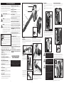
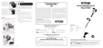
To stop the motor, release the throttle trigger and depress the
stop switch until the motor completely stops.Fig 11
Fig 11
Stop
Switch
MAINTENANCE OF THE DUST BAG
NOTE: The dust bag is a consumable part of this product
and normal wear and tear is not covered by the guarantee. Replacement bags can be purchased from your Ryobi
retailer.
Some helpful hints to prolong the life of the dust bag:
(1) Always ensure that the bag is fitted in accordance with
the instructions in this manual.
(2) When operating, ensure that the bag does not come in
contact with sharp objects.
(3) Do not vacuum damp leaves or garden debris.
(4) After use, ensure that the bag is free of debris and allow
to air for a few hours before storing.
AIR FILTER
It is recommended that the air filter is cleaned on a regular basis.
To clean the filter, remove the 4 air filter cover screws and cover.
Fig 12
Clean filter in warm soapy water and let dry completely before
replacing.
Fig 12
RYOBI TECHNOLOGIES AUSTRALIA PTY. LTD.
GUARANTEE
Subject to the guarantee condition below, this Ryobi tool
(hereinafter called “the product”) is guaranteed by Ryobi
(hereinafter called “the Company”) to be free from
defects in material or workmanship for a period of 12
months from the date of original purchase covering both
parts and labour. Under the terms of this guarantee, the
repair or replacement of any part shall be the opinion of
the Company or its authorised agent. Should service
become necessary during the guarantee period, the
owner should contact the Authorised Ryobi Retailer
from whom the Product was purchased, or the nearest
Company Branch Office. In order to obtain guarantee
service, the owner must present the sales docket and
Guarantee Certificate to confirm date of purchase. This
product is sold by the dealer or agent as principal and
the dealer has no authority from the Company to give
any additional guarantee on the Company’s behalf
except as herein contained or herein referred to.
OWNER’S OPERATING MANUAL
PETROL BLOWER/VAC
MODEL RPBV2500
which it was not-designed or is not suited; and no
repairs, alterations or modifications have been attempted by other than an Authorised Service Agent. This
guarantee will not apply if the tool is damaged by accident or if repairs arise from normal wear and tear.
The Company accepts no additional liability pursuant to
this guarantee for the costs of travelling or transportation of the Product or parts to and from the service dealer or agent - which costs are not included in this guarantee.
Certain legislation, including the Trade Practices Act,
1974 (as amended) and other state and territorial laws
give rights to the buyer and impose liability on the seller in certain circumstances. Nothing herein shall have
the effect of excluding, restricting or modifying any condition, guarantee, right or liability imposed, to the extent
only that such exclusion, restriction or modification
would render any term herein void.
Guarantee Conditions
This guarantee only applies provided that the Product
has been used in accordance with the manufacturer’s
recommendations under normal use and reasonable
care (in the opinion of the Company) and such guarantee
does not cover damage, malfunction or failure resulting
from misuse, neglect, abuse, or used for a purpose for
RYOBI TECHNOLOGIES AUSTRALIA PTY. LTD.
A.C.N. 002 277 509 Incorporated in N.S.W.
SYDNEY: 359-361 Horsley Road, Milperra, N.S.W.
2214, Phone: (02) 9772 2444
email: [email protected]
MELBOURNE: 960 Stud Road, Rowville, Vic, 3178,
Phone: (03) 9764 8655
PERTH:
33-35 Sorbonne Crescent, Canning Vale,
WA, 6155, Phone: (08) 9455 7775
HOBART:
All Enquiries Phone: 1300 361 505
ADELAIDE:
All Enquiries Phone: 1300 361 505
BRISBANE:
All Enquiries Phone: 1300 361 505
TOWNSVILLE: All Enquiries Phone: 1300 361 505
SPECIFICATION
Motor
25cc
Ignition
Electronic
Carburetor
Diaphragm, all position
Air Velocity
240 km/h
Mulching Ratio
12:1
Vacuum Bag Capacity
40 litre
Fuel Mixture
25:1
Weight (Blower only)
4.9 kg
(with bag & vac tubes)
5.75 kg
RYOBI TECHNOLOGIES NEW ZEALAND LIMITED
Auckland: 503 Mt Wellington Highway,
Mt Wellington, NZ, Phone: (09) 573 0230
email: [email protected]
THIS GUARANTEE FORM
SHOULD BE RETAINED BY THE CUSTOMER AT ALL TIMES
For your record and to assist in establishing date of purchase (necessary for in-guarantee service)
please keep your purchase docket and this form completed with the following particulars.
PURCHASED FROM _______________________________________________________
ADDRESS OF DEALER _____________________________________________________
DATE _________________MODEL NO ___________SERIAL NO ___________________
Present This Form With Your Purchase Docket When Guarantee Service Is Required
P5
THANK YOU FOR BUYING A RYOBI BLOWER/VAC.
Your new Blower/Vac has been engineered and manufactured to Ryobi's high standard for dependability, ease of operation, and operator safety. Properly cared for, it will give you years of rugged, trouble free performance.
CAUTION: Carefully read through this entire owner's manual before using your new Blower/Vac.
and
Pay close attention to the Rules for Safe Operation, Warnings and Cautions. If you use your Blower/Vac properly
only for what it is intended, you will enjoy years of safe, reliable service.
Thank You again for buying Ryobi tools.
RULES FOR SAFE OPERATION
The purpose of safety rules is to attract your attention to
possible dangers. The safety symbols and the explanations
with them, require your careful attention and understanding.
The safety warnings do not by themselves eliminate any danger. The instruction or warnings they give are not substitutes
for proper accident prevention measures.
SAFETY ALERT SYMBOL. Indicates caution or
warning. May be used in conjunction with other
symbols or pictures.
WARNING: Failure to obey a safety warning can
result in serious injury to yourself or to others.
Always follow the safety precautions to reduce
the risk of fire, electric shock and personal injury.
WARNING: Do not attempt to operate this tool
until you have read thoroughly and understood
completely, safety rules, etc. contained in this
manual. Failure to comply can result in accidents
involving fire, electric shock or serious personal
injury. Save owners manual and review frequently for continuing safe operation and instructing
others who may use this tool.
The operation of any tool can result in
foreign objects being thrown into your
eyes, which can result in severe eye
damage. Before beginning power tool
operation, always wear safety goggles
or safety glasses with side shields and a
full face shield when needed. We recommend Wide
Vision Safety Mask for use over eyeglasses or standard
safety glasses with side shields.
1. KNOW YOUR POWER TOOL. Read owners manual
carefully. Learn its applications and limitations as well as
the specific potential hazards related to this tool.
2. GUARD AGAINST ELECTRICAL SHOCK BY
PREVENTING BODY CONTACT WITH GROUNDED
SURFACES. For example, pipes, radiators, ranges,
refrigerator enclosures.
3. KEEP WORK AREA CLEAN. Cluttered areas and
benches invite accidents.
4. AVOID DANGEROUS ENVIRONMENT. Don't use
power tools in damp or wet locations or expose to rain.
Keep work area well lit.
5. KEEP CHILDREN AND VISITORS AWAY. Visitors should
wear safety glasses and be kept a safe distance from work
area. Do not let visitors contact tool or extension cord.
6. STORE IDLE TOOLS. When not in use, tools should be
stored in a dry and high or locked-up place, out of reach
of children.
7. DON'T FORCE TOOL. It will do the job better and safer
at the rate at which it was designed.
8. USE RIGHT TOOL. Don't force small tool or attachment
to do the job of a heavy duty tool. Don't use tool for
purpose not intended.
9. DRESS PROPERLY. Do not wear loose clothing or
jewellery. They can be caught in moving parts or sucked
into the machine. Rubber gloves and non-skid footwear
are recommended when working outdoors. Also wear
protective hair covering to contain long hair.
10. ALWAYS WEAR SAFETY GLASSES. Everyday
eyeglasses have only impact resistant lenses, they are
not safety glasses.
11. PROTECT YOUR LUNGS. Wear a dust mask if
operation is dusty.
12. PROTECT YOUR HEARING. Wear hearing protection
during extended periods of operation.
13. DON'T OVERREACH. Keep proper footing and balance
at all times. Do not use tool on a ladder or unstable
support. Secure tools when working at elevated levels.
14. MAINTAIN TOOLS WITH CARE. Keep tools sharp and
clean for better and safer performance. Follow
instructions for lubricating and changing accessories.
15. REMOVE ADJUSTING KEYS AND WRENCHES. Form a
habit of checking to see that keys and adjusting
wrenches are removed from tool before turning it on.
16. NEVER USE IN AN EXPLOSIVE ATMOSPHERE.
Normal sparking of the motor could ignite fumes.
17. KEEP HANDLES DRY, CLEAN AND FREE FROM OIL
AND GREASE. Always use a clean cloth when
cleaning. Never use brake fluids, gasoline, petroleum
based products, or any strong solvents to clean your tool.
18. STAY ALERT AND EXERCISE CONTROL. Watch what
you are doing and use common sense. Do not operate
tool when you are tired. Do not rush.
19. CHECK DAMAGED PARTS. Before further use of the
tool, a guard or any other part that is damaged should
be carefully checked to determine that it will operate
properly and perform its intended function. Check for
alignment of moving parts, binding of moving parts,
breakage of parts, mounting and any other conditions
that may affect its operation. A guard or any other part
that is damaged should be properly repaired or replaced
by an authorised service centre.
20. DO NOT USE TOOL IF SWITCH DOES NOT TURN IT
ON AND OFF. Have defective switches replaced by
authorised service centre.
21. DO NOT OPERATE THIS TOOL WHILE UNDER THE
INFLUENCE OF DRUGS, ALCOHOL OR ANY
MEDICATION.
P2
SAVE THESE INSTRUCTIONS
FOR FUTURE REFERENCE
Due to Ryobi's continued product refinement policy,product features and specifications can and will
change without notice. Check current features and
specifications with your Ryobi retailer.
Throttle Trigger
Handle
Stop
Switch
Vacuum
Inlet Cover
AIR DEFLECTOR Fig 6
Hook tabs 1 & 2, 3, 4, and 5 (in that order) onto blower
housing through slots. Make sure all 5 tabs are secured
onto housing.
Push down and in simultaneously on air deflector to lock
into place.
STARTING & STOPPING INSTRUCTIONS
Place blower on the ground. Fully depress and release the
primer bulb 5 to 7 times. Fuel should be visible in the
bulb. Fig 8
Fuel Tank
Fig 6
Blower
Tube
Primer Bulb
1&2
Nozzle
3
4
Starter
Rope
CHOKE POSITIONS
Full
Partial
Choke
Choke
2
n ASSEMBLY
BLOWER TUBES Turn nozzle clockwise to screw into
blower tube. Turn nozzle and tube clockwise to screw into
blower until tight Fig 1. Your machine is now ready for
blowing applications
Fig 1
1
Choke
Lever
Primer Bulb
OIL & FUEL MIXTURE
Thoroughly mix 200ml of 2 stroke oil to 5 litres of unleaded petrol in a container and fill the trimmer fuel tank. Fig
7. Care should be taken not to overfill the fuel tank which
will result in fuel splashing onto engine parts.
ATTACH VACUUM BAG
Remove nozzle from blower tube. Install vacuum bag over
blower tube, ensuring the end of the bag sleeve is completely covering the rib in the blower tube. Fig 4 & 5
Nozzle
Fig 7
Fig 4
Blower
Tube
Rib
Blower Tube
Partial
Choke
2
Fuel
Tank
CONVERTING BLOWER
TO VACUUM
Using a flat screwdriver,
loosen the locking screw
to open vacuum inlet cover
Fig 2.
WARNING:
Always
stop the
motor and allow
it to cool before re-filling the fuel tank. Failure
to adhere to this warning can result in vapour
explosion causing serious personal injury.
Vacuum Inlet
Cover
Locking
Bosses
Place the choke lever in the “Full Choke” (position 1). Fig
9
Fig 9
Air Deflector
Run
3
Fig 8
5
Locking
Screw
Blower
Tube
Vacuum
Tube
Fig 5
WARNING: Always mix petrol and oil in a separate container. Do not mix directly in the trimmer fuel tank which will cause motor damage
and void the warranty.
Full
Choke
1
Run
3
Squeeze throttle trigger fully and pull the starter rope
briskly until the motor sounds like it wants to start. Fig 10.
Move the choke lever to “Partial Choke” (position 2).
Squeeze throttle trigger fully and pull starter rope until the
Throttle
Trigger
WARNING
Fig 2
Align the 4 locking bosses
in inlet housing with slots
in upper vacuum tube.
Push vacuum tubes into
housing and turn clockwise
to lock in place. Fig 3
Vacuum
Bag
Upper
Vacuum
Tube
Fig 3
Wrap fastening strap tightly around the blower tube and
through the fastening loop. Rotate vacuum bag until
shoulder strap is upright and ensure that the bag is zipped
closed before starting the machine.
P3
If the machine becomes clogged,
under no circumstances should you
attempt to remove blockage from the
impeller with your hands.
To remove blockage, stop the motor
and remove the Dust Bag and Tubes.
Remove any debris from the impeller
with a stick. Failure to adhere to this
warning can and will result in serious
personal injury.
Fig 10
Starter Rope
motor starts.
Run motor approx. 30 seconds at full throttle before moving the choke lever to “Run” (position 3)
P4