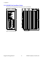
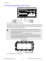
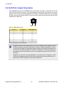
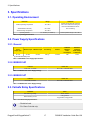
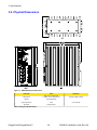
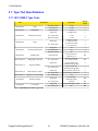
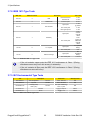
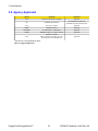
1
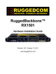
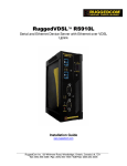
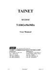
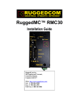
RuggedSwitch™
RS900GP
Hardware Installation Guide
Revision 100 - November 10, 2011
www.RuggedCom.com
RuggedSwitch™ RS900GP
RuggedSwitch™ RS900GP: Hardware Installation Guide
Copyright © 2011 RuggedCom Inc.
All Rights Reserved
Dissemination or reproduction of this document, or evaluation and communication of its contents, is not authorized except where expressly
permitted. Violations are liable for damages. All rights are reserved, particularly for the purposes of patent application or trademark registration.
This document contains proprietary information, which is protected by copyright. All rights are reserved. No part of this document may be
photocopied, reproduced or translated to another language without the prior written consent of RuggedCom Inc.
Disclaimer Of Liability
We have checked the contents of this manual against the hardware and software described. However, deviations from the description cannot
be completely ruled out.
RuggedCom shall not be liable for any errors or omissions contained herein or for consequential damages in connection with the furnishing,
performance, or use of this material.
The information given in this document is reviewed regularly and any necessary corrections will be included in subsequent editions. We appreciate
any suggested improvements. We reserve the right to make technical improvements without notice.
Registered Trademarks
ROX™, RuggedBackbone™, RuggedRated™ and eRSTP™ are trademarks of RuggedCom Inc. ROS®, RuggedRouter® and RuggedSwitch®
are registered trademarks of RuggedCom Inc. Other designations in this manual might be trademarks whose use by third parties for their own
purposes would infringe the rights of the owner.
Linux® is the registered trademark of Linus Torvalds in the U.S. and other countries.
The registered trademark Linux® is used pursuant to a sublicense from LMI, the exclusive licensee of Linus Torvalds, owner of the mark on
a world-wide basis.
Warranty
Five (5) years from date of purchase, return to factory. For warranty details, visit www.RuggedCom.com or contact your customer service
representative.
Contacting RuggedCom
Corporate Headquarters
US Headquarters
Europe Headquarters
RuggedCom Inc.
300 Applewood Crescent,
Concord, Ontario
Canada, L4K 5C7
Tel: +1 905 856 5288
Fax: +1 905 856 1995
Toll-free: 1 888 264 0006
RuggedCom
1930 Harrison Street, Suite 209
Hollywood, Florida
USA, 33020
Tel: +1 954 922 7938 ext.103
Fax: +1 954 922 7984
Toll-free: 1 888 264 0006
RuggedCom
Unit 41, Aztec Centre,
Aztec West, Almondsbury, Bristol
United Kingdom BS32 4TD
Tel: +44 1454 203 404
Fax: +44 1454 203 403
Email: [email protected]
Technical Support
Toll Free (North America): 1 866 922 7975
International: +1 905 856 5288
Email: [email protected]
Web: www.RuggedCom.com
RuggedSwitch™ RS900GP
Table of Contents
FCC Statement And Cautions ................................................................................................... 6
1. Product Overview ................................................................................................................... 7
1.1. RS900GP Front Panel ................................................................................................ 9
2. Installation ............................................................................................................................ 10
2.1. DIN Rail Mounting ..................................................................................................... 10
2.2. Panel Mounting Options ............................................................................................ 11
2.2.1. RS900GP Front Panel Mount Option ............................................................. 11
2.2.2. RS900GP Rear Panel Mount Option ............................................................. 12
2.2.3. RS900GP Side Panel Mount Option .............................................................. 13
2.3. DC Power Supply Wiring and Grounding ................................................................. 14
2.4. Failsafe Output Wiring and Specifications ................................................................ 15
2.5. RS232 Port Wiring .................................................................................................... 15
2.6. RJ45 Ports: Signal Description ................................................................................. 16
3. Specifications ....................................................................................................................... 17
3.1. Operating Environment ............................................................................................. 17
3.2. Power Supply Specifications ..................................................................................... 17
3.2.1. General ........................................................................................................... 17
3.2.2. IEEE802.3AF .................................................................................................. 17
3.2.3. IEEE802.3AT .................................................................................................. 17
3.3. Failsafe Relay Specifications .................................................................................... 17
3.4. Twisted Pair Data Port Specifications ....................................................................... 18
3.5. Fiber Optic Port Specifications .................................................................................. 19
3.6. Physical Dimensions ................................................................................................. 20
3.7. Type Test Specifications ........................................................................................... 21
3.7.1. IEC 61850-3 Type Tests ................................................................................ 21
3.7.2. IEEE 1613 Type Tests ................................................................................... 22
3.7.3. IEC Environmental Type Tests ...................................................................... 22
3.8. Agency Approvals ..................................................................................................... 23
A. Warranty .............................................................................................................................. 24
RuggedCom® RuggedSwitch™
3
RS900GP Installation Guide Rev 100
RuggedSwitch™ RS900GP
List of Figures
1.1.
2.1.
2.2.
2.3.
2.4.
2.5.
2.6.
2.7.
2.8.
2.9.
3.1.
RS900GP Front Panel ........................................................................................................ 9
DIN Rail Mounting ............................................................................................................ 10
Front Panel Mounting ....................................................................................................... 11
Rear Panel Mounting ........................................................................................................ 12
Side Panel Mounting ......................................................................................................... 13
DC Power Supply Wiring and Grounding ......................................................................... 14
RS900GP Chassis Ground Connection ............................................................................ 14
Failsafe Output Relay ....................................................................................................... 15
RS232 Female Connector ................................................................................................ 15
RJ45 Port Connector ........................................................................................................ 16
RS900GP Physical Dimensions ........................................................................................ 20
RuggedCom® RuggedSwitch™
4
RS900GP Installation Guide Rev 100
RuggedSwitch™ RS900GP
List of Tables
1.1. Front Panel LED Definitions ............................................................................................... 9
2.1. RS232 Female DCE Pinout .............................................................................................. 15
2.2. RJ45 Ethernet Pin Assignment ......................................................................................... 16
3.1. Operating Environment ..................................................................................................... 17
3.2. RS900GP Power Supply Specifications ........................................................................... 17
3.3. IEEE802.3AF Power Supply Ratings ................................................................................ 17
3.4. IEEE802.3AT Power Supply Ratings ................................................................................ 17
3.5. Failsafe Relay Specifications ............................................................................................ 17
3.6. Twisted Pair Data Port Specifications ............................................................................... 18
3.7. Fiber Optic Port Specifications ......................................................................................... 19
3.8. Physical Specifications ...................................................................................................... 20
3.9. RS900GP IEC 61850-3 Type Tests ................................................................................. 21
3.10. RS900GP IEEE 1613 Type Tests .................................................................................. 22
3.11. IEC Environmental Type Tests ....................................................................................... 22
3.12. Agency Approvals ........................................................................................................... 23
RuggedCom® RuggedSwitch™
5
RS900GP Installation Guide Rev 100
FCC Statement And Cautions
FCC Statement And Cautions
Federal Communications Commission Radio Frequency Interference
Statement
This equipment has been tested and found to comply with the limits for a Class A digital device
pursuant to Part 15 of the FCC Rules. These limits are designed to provide reasonable protection
against harmful interference when the equipment is operated in a commercial environment. This
equipment generates, uses and can radiate radio frequency energy and, if not installed and used in
accordance with the instruction manual, may cause harmful interference to radio communications.
Operation of this equipment in a residential area is likely to cause harmful interference in which
case the user will be required to correct the interference at his own expense.
Caution: LASER
This product contains a laser system and is classified as a CLASS 1 LASER
PRODUCT. Use of controls or adjustments or performance of procedures other than
those specified herein may result in hazardous radiation exposure.
Caution: Service
This product contains no user-serviceable parts. Attempted service by unauthorized
personnel shall render all warranties null and void.
Changes or modifications not expressly approved by RuggedCom Inc. could invalidate
specifications, test results, and agency approvals, and void the user’s authority to
operate the equipment.
Should this device require service, refer to Appendix A, Warranty in this guide.
Caution: Physical Access
This product should be installed in a restricted access location where access can only
be gained by service personnel or users who have been instructed about the reasons
for the restrictions applied to the location and about any precautions that shall be taken;
and access is through the use of a tool or lock and key, or other means of security,
and is controlled by the authority responsible for the location.
Caution: Hot Surfaces
When in operation, regions of the unit surface may be hot.
Caution: Lithium Battery
This product contains a Lithium battery that is not replaceable by the operator or by
service personnel.
RuggedCom® RuggedSwitch™
6
RS900GP Installation Guide Rev 100
1. Product Overview
1. Product Overview
The RuggedSwitch™ RS900GP is an industrially hardened, fully managed Ethernet switch
providing dual fiber optical Gigabit Ethernet ports and eight Fast Ethernet copper ports - each
capable of supplying high power 802.3at compliant power over Ethernet. Designed to operate
reliably in harsh industrial environments, the RS900GP provides a high level of immunity to
electromagnetic interference and heavy electrical surges typical of environments found in electric
utility substations, factory floors or in curb side traffic control cabinets. An operating temperature
range of -40°C to +85°C coupled with hazardous location certification, a powder coated aluminum
enclosure and optional conformal coating allows the RS900GP to be placed in almost any location.
The embedded Rugged Operating System (ROS™) provides advanced networking features such
as Enhanced Rapid Spanning Tree (eRSTP™), Port Rate Limiting and a full array of intelligent
functionality for high network availability and manageability.
Ethernet Ports
• Up to 2 - Fiber Optic Gigabit-Ethernet Ports(100/1000BaseX)
• 8 - Fast Ethernet Ports (10/100BaseTX) all external 802.3af/802.3at compliant PoE
• Up to 2 - 10/100/1000 BaseTX copper ports
• Full compliance with IEEE: 802.3, 802.3u and 802.3z
• Non-blocking, store and forward switching
• Full duplex operation and flow control (IEEE 802.3x)
• Industry standard fiber optical connectors: LC, SC, SFP
• Bi-Directional simplex fiber support
• Long haul optics allow Gigabit distances up to 70km
Power Over Ethernet (PoE)
• 8-10/100 BaseTx 802.3af/802.3at compliant ports
• Data and power over a single Ethernet cable
• Auto-sensing ports that provide power only to PoE end devices
RuggedRated™ for Reliability in Harsh Environments
• Meets IEEE 1613 (electric utility substations)
• Exceeds IEC 61850-3 (electric utility substations)
• Exceeds IEEE 61800-3 (variable speed drive systems)
• Exceeds IEC 61000-6-2 (generic industrial environment)
• Exceeds NEMA TS-2 (traffic control equipment)
• Hazardous Location Certification: Class 1 Division 2
• -40 to +85°C operating temperature (no fans)
• Conformal coated circuit boards (optional)
• Rugged powder coated aluminum enclosure
RuggedCom® RuggedSwitch™
7
RS900GP Installation Guide Rev 100
1. Product Overview
Power Supply
• 2 (redundant) 54VDC inputs (51-57VDC)
• Supports 8 30W PoE powered devices (minimum 260W total output)
• Supports power supply sharing
• Reverse polarity protection
• CSA/UL 60950 safety approved to +85°C
Simple Plug and Play Operation
• Plug and play operation 802.3af/802.3at
• Automatic learning of up to 8192 MAC addresses
• Auto-negotiation on all 10/100BaseTX ports
• Auto-MDI/MDIX (crossover) on all 10/100BaseTX ports
• LED indicators for Link/Activity and Power
ROS™ Advanced Network Management
• Enhanced Rapid Spanning Tree (eRSTPTM)
• Quality of Service (802.1p) for real-time traffic
• Port rate limiting: 128kbps to 8Mbps
• VLAN (802.1q) with double tagging
• IGMP Snooping for multicast filtering
• Port configuration, status, statistics, mirroring, security
• Loss of link management on fiber ports
• Web-based, Telnet, CLI management interfaces
• SNMP v2 and RMON
• Rich set of diagnostics with logging and alarms
RuggedCom® RuggedSwitch™
8
RS900GP Installation Guide Rev 100
1. Product Overview
1.1. RS900GP Front Panel
Figure 1.1. RS900GP Front Panel
LED Indicator
LED Color and State
Power LED
Green, steady.
Alarm LED
Red, steady.
Description
Power is on.
Alarm condition exists.
Ethernet Port 1-8 Link LED
Green, steady.
Network link.
Ethernet Port 1-8 Link LED
Green, blinking.
Network activity.
Ethernet Port 1-8 PoE LED
Orange, steady.
PoE is enabled and powered on.
Ethernet Port 1-8 PoE LED
Orange, blinking.
PoE is enabled and powered off.
Ethernet Port 1-8 PoE LED
Off.
PoE is disabled.
Table 1.1. Front Panel LED Definitions
RuggedCom® RuggedSwitch™
9
RS900GP Installation Guide Rev 100
2. Installation
2. Installation
2.1. DIN Rail Mounting
An optional DIN rail mounting bracket is available for the RS900GP.
Figure 2.1. DIN Rail Mounting
RuggedCom® RuggedSwitch™
10
RS900GP Installation Guide Rev 100
2. Installation
2.2. Panel Mounting Options
The RS900GP can be equipped with front, rear, or side panel mount brackets.
2.2.1. RS900GP Front Panel Mount Option
The front panel mounting brackets fit flush with the front of the RS900GP.
Figure 2.2. Front Panel Mounting
RuggedCom® RuggedSwitch™
11
RS900GP Installation Guide Rev 100
2. Installation
2.2.2. RS900GP Rear Panel Mount Option
The rear panel mounting brackets fit flush with the rear of the RS900GP.
Figure 2.3. Rear Panel Mounting
RuggedCom® RuggedSwitch™
12
RS900GP Installation Guide Rev 100
2. Installation
2.2.3. RS900GP Side Panel Mount Option
The side panel mounting brackets fit flush with the side of the RS900GP.
Figure 2.4. Side Panel Mounting
RuggedCom® RuggedSwitch™
13
RS900GP Installation Guide Rev 100
2. Installation
2.3. DC Power Supply Wiring and Grounding
Figure 2.5. DC Power Supply Wiring and Grounding
The RS900GP low voltage DC power supply features reverse polarity protection and dual
independent inputs. This feature allows the connection of two DC sources with the same nominal
voltage to provide redundant power supply inputs. The DC source must be connected to the DC
inputs according to the polarity markings on the unit.
1. Equipment must be installed according to the applicable country wiring codes.
2. Surge Ground should be connected to Chassis Ground via a braided cable or
other appropriate ground wire.
3. Chassis Ground must be connected to the protective earth.
4. All line-to-ground transient energy is shunted to the Surge Ground terminal. In
cases where users require the DC inputs to be isolated from ground, remove the
ground braid between Surge and Chassis Ground. Note that all line-to-ground
transient protection circuitry will be disabled.
Figure 2.6. RS900GP Chassis Ground Connection
RuggedCom® RuggedSwitch™
14
RS900GP Installation Guide Rev 100
2. Installation
2.4. Failsafe Output Wiring and Specifications
The “Failsafe” output relay is provided to signal critical error conditions that may occur on the
RS900GP. The contacts are energized upon power up of the unit and remain energized until an
alarm condition or power loss occurs.
Figure 2.7. Failsafe Output Relay
2.5. RS232 Port Wiring
The RS232 port is used for configuring the unit. A straight-through serial cable with a DB-9
connector is required. There is no need to crossover the Transmit and Receive signals from the
PC side since this has been done internally as shown in the figure below.
Figure 2.8. RS232 Female Connector
Pin
Signal
1
No Connection
2
Transmit Data
3
Receive Data
4
No Connection
5
Ground
6
No Connection
7
No Connection
8
No Connection
9
No Connection
Table 2.1. RS232 Female DCE Pinout
This port is not intended to be a permanent connection and the cable shall be less
than 2m (6.5 ft) in length.
RuggedCom® RuggedSwitch™
15
RS900GP Installation Guide Rev 100
2. Installation
2.6. RJ45 Ports: Signal Description
The RS900GP has several 10/100BaseTX ports that allow connection to standard CAT-5 UTP
cable with RJ45 male connectors. The RJ45 receptacles are directly connected to the chassis
ground on the unit and can accept shielded CAT-5 cables. If shielded cables are used, care must
be taken to ensure the shielded cables do not form a ground loop via the shield wire and the RJ45
receptacles at either end.
Figure 2.9. RJ45 Port Connector
RJ45 Pin
10/100Base-Tx
10/100/1000Base-Tx
1
RX+
A+
2
RX-
A-
3
TX+
B+
4
NC
C+
5
NC
C-
6
TX-
B-
7
NC
D+
8
NC
D-
Table 2.2. RJ45 Ethernet Pin Assignment
RuggedCom does not recommend the use of CAT-5 cabling of any length for critical
real-time substation automation applications. However, transient suppression circuitry
is present on all copper ports to protect against damage from electrical transients and
to ensure IEC 61850-3 and IEEE 1613 Class 1 conformance. This means that during
the transient event communications errors or interruptions may occur but recovery is
automatic.
RuggedCom also does not recommended to use these ports to interface to field
devices across distances which could produce high levels of ground potential rise, (i.e.
greater than 2500V) during line to ground fault conditions.
RuggedCom® RuggedSwitch™
16
RS900GP Installation Guide Rev 100
3. Specifications
3. Specifications
3.1. Operating Environment
Parameter
Ambient Operating Temperature
Range
Comments
-40 to 85°C
Ambient Temperature as measured
from a 30cm radius surrounding the
center of the RS900GP enclosure.
Non-condensing
Ambient Relative Humidity
5% to 95%
Ambient Storage Temperature
-40 to 85°C
Operating Altitude
0 to 15240m (0 to 50000 ft)
Over temperature range of -40 to 85°C
Table 3.1. Operating Environment
3.2. Power Supply Specifications
3.2.1. General
a
Power
Supply Type
Minimum Input
Maximum Input
54 VDC
45 VDC
57 VDC
Fuse Rating
6.3A (T)
a
Isolation
RS900GP
Maximum
Power
Consumption
Maximum
Combined
Power Output
at PoE Ports
1.5 kV DC
15W
273W
(T) denotes time-delay fuse
Table 3.2. RS900GP Power Supply Specifications
3.2.2. IEEE802.3AF
Power In
Power Out
45-57 VDC, 3.5 A MAX
44-57 VDC, 15 W/PORT MAX
Table 3.3. IEEE802.3AF Power Supply Ratings
3.2.3. IEEE802.3AT
Power In
Power Out
51-57 VDC, 6 A MAX
50-57 VDC, 30 W/PORT MAX
Table 3.4. IEEE802.3AT Power Supply Ratings
3.3. Failsafe Relay Specifications
Parameter
Value
Max Switching Voltage
30VAC, 80VDC
Rated Switching Current
0.3A @ 30VAC
1A @ 30VDC, 0.3A @ 80VDC
Table 3.5. Failsafe Relay Specifications
• Resistive Load.
• For Class-2 circuits only.
RuggedCom® RuggedSwitch™
17
RS900GP Installation Guide Rev 100
3. Specifications
3.4. Twisted Pair Data Port Specifications
Data Port
Media
Distance
Connector Type
10/100 Mbps
Cat 5 UTP or STP
100m
RJ45
Table 3.6. Twisted Pair Data Port Specifications
RuggedCom® RuggedSwitch™
18
RS900GP Installation Guide Rev 100
3. Specifications
3.5. Fiber Optic Port Specifications
For maximum flexibility, RuggedCom Inc. offers a number of different transceiver choices for
Gigabit fiber optic communications. The following table details fiber optic specifications based on
the order code/transceiver selected at time of ordering.
Mode /
Connector
Tx λ (nm)
Cable
a
Type 1.
2LCMM
MM / LC
850
50µ/125
-9.5 / -4
-20
0
0.5
2LC10
SM / LC
1310
9µ/125
-9.5 / -3
-22
-3
10
2LC25
SM / LC
1310
9µ/125
-5 / 0
-22
-3
25
2SC10
SM / SC
1310
9µ/125
-10 / -3
-22
-3
10
2SC25
SM / SC
1310
9µ/125
-7 / -3
-24
-3
25
SFP
MM / LC
850
50µ/125
-8.5 / -4
-22
-3
0.5
SFP
SM / LC
1310
9µ/125
-9 / -3
-24
0
10
SFP
SM / LC
1310
9µ/125
-7 / -3
-26
-3
25
d
SM / LC
1550
9µ/125
-5 / 0
-26
0
50
d
SM / LC
1550
9µ/125
0/5
-26
0
80
SM / SC
Simplex
1310
9µ/125
-9 / -3
-22
-3
10
SM / SC
Simplex
1490
9µ/125
-9 / -3
-22
-3
10
SFP
SFP
SFP
SFP
d
Tx Pwr (dBm) Rx Sensitivity Rx Saturation
b
b
b
(Min/Max)
(dBm)
(dBm)
Typical
Distance
c
(km)
Order Code
a
All cabling is duplex type unless otherwise specified.
All optical power numbers are listed as dBm averages.
c
Maximum segment length is greatly dependent on factors such as fiber quality, and number of patches and splices.
Please consult RuggedCom sales associates when determining maximum segment distances.
d
These transceivers utilize a distributed feedback (DFB) type laser and are rated for -20#C to +85#C operation only.
b
Table 3.7. Fiber Optic Port Specifications
RuggedCom® RuggedSwitch™
19
RS900GP Installation Guide Rev 100
3. Specifications
3.6. Physical Dimensions
Figure 3.1. RS900GP Physical Dimensions
Parameter
Value
Comments
Dimensions
6.95 × 3.63 × 6.08 inches
( 17.653 × 9.22 × 14.4432 cm)
(Length × Width × Depth
Weight
To be determined
Ingress Protection
IP40
Enclosure
Cast Aluminum
(1mm objects)
Table 3.8. Physical Specifications
RuggedCom® RuggedSwitch™
20
RS900GP Installation Guide Rev 100
3. Specifications
3.7. Type Test Specifications
3.7.1. IEC 61850-3 Type Tests
Test
Test Levels
Severity
Levels
Enclosure Contact
+/- 8kV
4
Description
IEC 61000-4-2
ESD
Enclosure Air
+/- 15kV
4
IEC 61000-4-3
Radiated RFI
Enclosure ports
20 V/m
x
Signal ports
+/- 2kV @ 2.5kHz
x
IEC 61000-4-4
Burst (Fast Transient)
D.C. Power ports
+/- 2kV
4
Earth ground ports
+/- 2kV
4
Signal ports
+/- 2kV line-to-earth,
+/- 1.5kV line-to-line
4
D.C. Power ports
+/- 1.5kV line-to-earth,
+/- 1kV line-to-line
3
Signal ports
10V
3
IEC 61000-4-5
IEC 61000-4-6
Surge
Induced (Conducted) RFI
D.C Power ports
10V
3
Earth ground ports
10V
3
IEC 61000-4-8
Magnetic Field
Enclosure ports
40 A/m continuous,
1000 A/m for 1 s
N/A
IEC 61000-4-29
Voltage Dips & Interrupts
D.C. Power ports
30% for 0.1s, 60% for
0.1s, 100% for 0.05s
N/A
Signal ports
2.5kV common, 1kV
differential mode @ 1MHz
3
D.C. Power ports
2.5kV common, 1kV
differential mode @ 1MHz
3
Signal ports
30V Continuous, 300V for 1s
4
D.C. Power ports
30V Continuous, 300V for 1s
4
D.C. Power ports
10%
3
Signal ports
1.5kV AC (FailSafe Relay output)
N/A
D.C. Power ports
1.5kV DC
N/A
Signal ports
5kV (Fail-Safe Relay output)
N/A
D.C. Power ports
5kV
N/A
IEC 61000-4-12
Damped Oscillatory
IEC 61000-4-16
Mains Frequency Voltage
IEC 61000-4-17
Ripple on D.C. Power Supply
IEC 60255-5
Dielectric Strength
IEC 60255-5
H.V. Impulse
Table 3.9. RS900GP IEC 61850-3 Type Tests
RuggedCom® RuggedSwitch™
21
RS900GP Installation Guide Rev 100
3. Specifications
3.7.2. IEEE 1613 Type Tests
IEEE Test
IEEE 1613 Clause
Description
C37.90.3
9
ESD
C37.90.2
8
Radiated RFI
C37.90.1
7
C37.90.1
Fast Transient
7
C37.90
+/- 8kV
Enclosure Air
+/- 12kV
Enclosure ports
35 V/m
Signal ports
+/- 2kV
@ 2.5kHz
D.C. Power ports
+/- 2kV
Earth ground ports
+/- 2kV
Signal ports
2.2kV
common
mode @
1MHz
D.C. Power ports
2.2kV
common &
differential
mode @
1MHz
Signal ports
5 kV (Failsafe
Relay)
D.C. Power ports
5 kV
Signal ports
2kV
AC(Failsafe
Relay)
D.C. Power ports
1.2kV DC
Oscillatory
6
C37.90
Test Levels
Enclosure Contact
H.V. Impulse
6
Dielectric Strength
Table 3.10. RS900GP IEEE 1613 Type Tests
• If the unit contains copper ports the IEEE 1613 conformance is Class 1 (During
disturbance errors may occur but recovery is automatic).
• If the unit contains all fiber ports the IEEE 1613 conformance is Class 2 (During
disturbance no errors will occur).
3.7.3. IEC Environmental Type Tests
Test
Description
Test Levels
Severity Levels
IEC 60068-2-1
Cold Temperature
Test Ad
-40°C, 16 Hours
N/A
IEC 60068-2-2
Dry Heat
Test Bd
+85°C, 16 Hours
N/A
IEC 60068-2-30
Humidity (Damp
Heat, Cyclic)
Test Db
95% (non-condensing),
55°C, 6 cycles
N/A
IEC 60255-21-1
Vibration
2g @ (10-150) Hz
Class 2
IEC 60255-21-2
Shock
30g @ 11 ms
Class 2
Table 3.11. IEC Environmental Type Tests
RuggedCom® RuggedSwitch™
22
RS900GP Installation Guide Rev 100
3. Specifications
3.8. Agency Approvals
Agency
Standards
Comments
CSA
CSA C22.2 No. 60950, UL 60950
Approved
CE
EN 60950, EN 61000-6-2
CE Compliance is claimed via
Declaration of Self Conformity Route
FCC Part 15, Class A
Approved
EN55022, Class A
Approved
FDA/CDRH
21 CFR Chapter 1, Subchapter J
Approved
IEC/EN
EN60825-1:1994 + A11:1996 + A2:2001
Approved
CSA
Hazardous Locations
Class 1, Division 2, Groups A, B, C,& D.
T6 rating at 40°C, T4A rating at 85°C
Approved
FCC
a
CISPR
a
With the use of shielded Ethernet cables.
Table 3.12. Agency Approvals
RuggedCom® RuggedSwitch™
23
RS900GP Installation Guide Rev 100
Appendix A. Warranty
Appendix A. Warranty
RuggedCom warrants this product for a period of five (5) years from the date of purchase. This
product contains no user-serviceable parts. Attempted service by unauthorized personnel shall
render all warranties null and void. For warranty details, visit www.RuggedCom.com or contact
your customer service representative.
Should this product require service, contact the factory at:
RuggedCom Inc.
300 Applewood Crescent
Concord, Ontario
Canada L4K 5C7
Phone: +1 905 856 5288
Fax: +1 905 856 1995
RuggedCom® RuggedSwitch™
24
RS900GP Installation Guide Rev 100