1
To resize thickness, move all items on the front cover
and center registration marks to left or right
Information
AFRICA
EGYPT
Al Fanny Trading Office
9, EBN Hagar A1 Askalany
Street,
ARD E1 Golf, Heliopolis,
Cairo 11341, EGYPT
TEL: 20-2-417-1828
REUNION
Maison FO - YAM Marcel
25 Rue Jules Hermann,
Chaudron - BP79 97 491
Ste Clotilde Cedex,
REUNION ISLAND
TEL: (0262) 218-429
SOUTH AFRICA
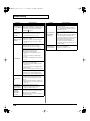
When you need repair service, call your nearest Roland Service Center or authorized Roland
distributor in your country as shown below.
PHILIPPINES
COSTA RICA
TRINIDAD
NORWAY
JORDAN
G.A. Yupangco & Co. Inc.
339 Gil J. Puyat Avenue
Makati, Metro Manila 1200,
PHILIPPINES
TEL: (02) 899 9801
JUAN Bansbach Instrumentos
Musicales
Ave.1. Calle 11, Apartado 10237,
San Jose, COSTA RICA
TEL: 258-0211
AMR Ltd
Ground Floor
Maritime Plaza
Barataria Trinidad W.I.
TEL: (868) 638 6385
MUSIC HOUSE CO. LTD.
FREDDY FOR MUSIC
P. O. Box 922846
Amman 11192 JORDAN
TEL: (06) 5692696
SINGAPORE
CURACAO
URUGUAY
Roland Scandinavia Avd.
Kontor Norge
Lilleakerveien 2 Postboks 95
Lilleaker N-0216 Oslo
NORWAY
TEL: 2273 0074
SWEE LEE MUSIC
COMPANY PTE. LTD.
150 Sims Drive,
SINGAPORE 387381
TEL: 6846-3676
Zeelandia Music Center Inc.
Orionweg 30
Curacao, Netherland Antilles
TEL:(305)5926866
Todo Musica S.A.
Francisco Acuna de Figueroa
1771
C.P.: 11.800
Montevideo, URUGUAY
TEL: (02) 924-2335
POLAND
MX MUSIC SP.Z.O.O.
UL. Gibraltarska 4.
PL-03664 Warszawa POLAND
TEL: (022) 679 44 19
EASA HUSAIN AL-YOUSIFI
& SONS CO.
Abdullah Salem Street,
Safat, KUWAIT
TEL: 243-6399
PORTUGAL
LEBANON
Roland Iberia, S.L.
Portugal Office
Cais das Pedras, 8/9-1 Dto
4050-465, Porto, PORTUGAL
TEL: 22 608 00 60
Chahine S.A.L.
Gerge Zeidan St., Chahine
Bldg., Achrafieh, P.O.Box: 165857
Beirut, LEBANON
TEL: (01) 20-1441
TAIWAN
ROLAND TAIWAN
ENTERPRISE CO., LTD.
Room 5, 9fl. No. 112 Chung
Shan N.Road Sec.2, Taipei,
TAIWAN, R.O.C.
TEL: (02) 2561 3339
That Other Music Shop(PTY)Ltd.
11 Melle St., Braamfontein,
Johannesbourg,
SOUTH AFRICA
TEL: (011) 403 4105
FAX: (011) 403 1234
THAILAND
Paul Bothner(PTY)Ltd.
Royal Cape Park, Unit 24
Londonderry Road, Ottery 7800
Cape Town, SOUTH AFRICA
TEL: (021) 799 4900
VIETNAM
ASIA
CHINA
Roland Shanghai Electronics
Co.,Ltd.
5F. No.1500 Pingliang Road
Shanghai 200090, CHINA
TEL: (021) 5580-0800
Roland Shanghai Electronics
Co.,Ltd.
(BEIJING OFFICE)
10F. No.18 3 Section Anhuaxili
Chaoyang District Beijing
100011 CHINA
TEL: (010) 6426-5050
Roland Shanghai Electronics
Co.,Ltd.
(GUANGZHOU OFFICE)
2/F., No.30 Si You Nan Er Jie
Yi Xiang, Wu Yang Xin Cheng,
Guangzhou 510600, CHINA
TEL: (020) 8736-0428
HONG KONG
Theera Music Co. , Ltd.
330 Soi Verng NakornKasem,
New Road, Sumpantawongse,
Bangkok 10100, THAILAND
TEL: (02) 224-8821
SAIGON MUSIC
DISTRIBUTOR
(TAN DINH MUSIC)
138 Tran Quang Khai Street
Dist. 1, Ho Chi Minh City
VIETNAM
TEL: (08) 848-4068
AUSTRALIA/
NEW ZEALAND
AUSTRALIA/
NEW ZEALAND
Roland Corporation
Australia Pty.,Ltd.
38 Campbell Avenue
Dee Why West. NSW 2099
AUSTRALIA
For Australia
Tel: (02) 9982 8266
For New Zealand
Tel: (09) 3098 715
CENTRAL/LATIN
AMERICA
Tom Lee Music Co., Ltd.
Service Division
22-32 Pun Shan Street, Tsuen
Wan, New Territories,
HONG KONG
TEL: 2415 0911
ARGENTINA
Parsons Music Ltd.
8th Floor, Railway Plaza, 39
Chatham Road South, T.S.T,
Kowloon, HONG KONG
TEL: 2333 1863
BARBADOS
INDIA
Rivera Digitec (India) Pvt. Ltd.
409, Nirman Kendra
Mahalaxmi Flats Compound
Off. Dr. Edwin Moses Road,
Mumbai-400011, INDIA
TEL: (022) 2493 9051
INDONESIA
PT Citra IntiRama
J1. Cideng Timur No. 15J-150
Jakarta Pusat
INDONESIA
TEL: (021) 6324170
KOREA
Cosmos Corporation
1461-9, Seocho-Dong,
Seocho Ku, Seoul, KOREA
TEL: (02) 3486-8855
MALAYSIA
Roland Asia Pacific Sdn. Bhd.
45-1, Block C2, Jalan PJU 1/39,
Dataran Prima, 47301 Petaling
Jaya, Selangor, MALAYSIA
TEL: (03) 7805-3263
Instrumentos Musicales S.A.
Av.Santa Fe 2055
(1123) Buenos Aires
ARGENTINA
TEL: (011) 4508-2700
A&B Music Supplies LTD
12 Webster Industrial Park
Wildey, St.Michael, Barbados
TEL: (246)430-1100
BRAZIL
Roland Brasil Ltda.
Rua San Jose, 780 Sala B
Parque Industrial San Jose
Cotia - Sao Paulo - SP, BRAZIL
TEL: (011) 4615 5666
CHILE
Comercial Fancy II S.A.
Rut.: 96.919.420-1
Nataniel Cox #739, 4th Floor
Santiago - Centro, CHILE
TEL: (02) 688-9540
COLOMBIA
Centro Musical Ltda.
Cra 43 B No 25 A 41 Bododega 9
Medellin, Colombia
TEL: (574)3812529
DOMINICAN REPUBLIC
Instrumentos Fernando Giraldez
Calle Proyecto Central No.3
Ens.La Esperilla
Santo Domingo,
Dominican Republic
TEL:(809) 683 0305
ECUADOR
Mas Musika
Rumichaca 822 y Zaruma
Guayaquil - Ecuador
TEL:(593-4)2302364
VENEZUELA
Instrumentos Musicales
Allegro,C.A.
Av.las industrias edf.Guitar
import
#7 zona Industrial de Turumo
Caracas, Venezuela
TEL: (212) 244-1122
ROMANIA
EL SALVADOR
OMNI MUSIC
75 Avenida Norte y Final
Alameda Juan Pablo II,
Edificio No.4010 San Salvador,
EL SALVADOR
TEL: 262-0788
GUATEMALA
Casa Instrumental
Calzada Roosevelt 34-01,zona 11
Ciudad de Guatemala
Guatemala
TEL:(502) 599-2888
HONDURAS
Almacen Pajaro Azul S.A. de C.V.
BO.Paz Barahona
3 Ave.11 Calle S.O
San Pedro Sula, Honduras
TEL: (504) 553-2029
MARTINIQUE
Musique & Son
Z.I.Les Mangle
97232 Le Lamantin
Martinique F.W.I.
TEL: 596 596 426860
AUSTRIA
Roland Iberia, S.L.
Paseo García Faria, 33-35
08005 Barcelona SPAIN
TEL: 93 493 91 00
BELGIUM/FRANCE/
HOLLAND/
LUXEMBOURG
NICARAGUA
Bansbach Instrumentos
Musicales Nicaragua
Altamira D'Este Calle Principal
de la Farmacia 5ta.Avenida
1 Cuadra al Lago.#503
Managua, Nicaragua
TEL: (505)277-2557
PANAMA
SUPRO MUNDIAL, S.A.
Boulevard Andrews, Albrook,
Panama City, REP. DE
PANAMA
TEL: 315-0101
PARAGUAY
Distribuidora De
Instrumentos Musicales
J.E. Olear y ESQ. Manduvira
Asuncion PARAGUAY
TEL: (595) 21 492147
Roland Scandinavia A/S
SWEDISH SALES OFFICE
Danvik Center 28, 2 tr.
S-131 30 Nacka SWEDEN
TEL: (0)8 702 00 20
CZECH REP.
K-AUDIO
Kardasovska 626.
CZ-198 00 Praha 9,
CZECH REP.
TEL: (2) 666 10529
UKRAINE
U.A.E.
Roland (U.K.) Ltd.
Atlantic Close, Swansea
Enterprise Park, SWANSEA
SA7 9FJ,
UNITED KINGDOM
TEL: (01792) 702701
STOLLAS S.A.
Music Sound Light
155, New National Road
Patras 26442, GREECE
TEL: 2610 435400
CANADA
BAHRAIN
Moon Stores
No.16, Bab Al Bahrain Avenue,
P.O.Box 247, Manama 304,
State of BAHRAIN
TEL: 17 211 005
HUNGARY
Roland East Europe Ltd.
Warehouse Area ‘DEPO’ Pf.83
H-2046 Torokbalint,
HUNGARY
TEL: (23) 511011
CYPRUS
Radex Sound Equipment Ltd.
17, Diagorou Street, Nicosia,
CYPRUS
TEL: (022) 66-9426
IRAN
MOCO INC.
No.41 Nike St., Dr.Shariyati Ave.,
Roberoye Cerahe Mirdamad
Tehran, IRAN
TEL: (021) 285-4169
ITALY
ISRAEL
Roland Italy S. p. A.
Viale delle Industrie 8,
20020 Arese, Milano, ITALY
TEL: (02) 937-78300
Zak Electronics & Musical
Instruments Co. L.L.C.
Zabeel Road, Al Sherooq Bldg.,
No. 14, Grand Floor, Dubai,
U.A.E.
TEL: (04) 3360715
NORTH AMERICA
MIDDLE EAST
GREECE
Roland Ireland
G2 Calmount Park, Calmount
Avenue, Dublin 12
Republic of IRELAND
TEL: (01) 4294444
Audionet
Distribuciones Musicales SAC
Juan Fanning 530
Miraflores
Lima - Peru
TEL: (511) 4461388
ZUHAL DIS TICARET A.S.
Galip Dede Cad. No.37
Beyoglu - Istanbul / TURKEY
TEL: (0212) 249 85 10
UNITED KINGDOM
Roland Elektronische
Musikinstrumente HmbH.
Oststrasse 96, 22844
Norderstedt, GERMANY
TEL: (040) 52 60090
Roland Canada Music Ltd.
(Head Office)
5480 Parkwood Way
Richmond B. C., V6V 2M4
CANADA
TEL: (604) 270 6626
Roland Canada Music Ltd.
(Toronto Office)
170 Admiral Boulevard
Mississauga On L5T 2N6
CANADA
TEL: (905) 362 9707
U. S. A.
Roland Corporation U.S.
5100 S. Eastern Avenue
Los Angeles, CA 90040-2938,
U. S. A.
TEL: (323) 890 3700
Halilit P. Greenspoon & Sons
Ltd.
8 Retzif Ha'aliya Hashnya St.
Tel-Aviv-Yafo ISRAEL
TEL: (03) 6823666
As of December 10, 2005 (ROLAND)
*
0
3
7
8
8
7
1
2
-
0
Before using this unit, carefully read the sections entitled: “IMPORTANT SAFETY
INSTRUCTIONS” (p. 2), “USING THE UNIT SAFELY” (p. 3), and “IMPORTANT NOTES”
(p. 5). These sections provide important information concerning the proper operation of
the unit. Additionally, in order to feel assured that you have gained a good grasp of
every feature provided by your new unit, owner’s manual should be read in its entirety.
The manual should be saved and kept on hand as a convenient reference.
TURKEY
TIC-TAC
Mira Str. 19/108
P.O. Box 180
295400 Munkachevo,
UKRAINE
TEL: (03131) 414-40
GERMANY
P.O.Box 2154, Alkhobar 31952
SAUDI ARABIA
TEL: (03) 898 2081
201b
Technical Light & Sound
Center
Rawda, Abdul Qader Jazairi St.
Bldg. No. 21, P.O.BOX 13520,
Damascus, SYRIA
TEL: (011) 223-5384
Roland (Switzerland) AG
Landstrasse 5, Postfach,
CH-4452 Itingen,
SWITZERLAND
TEL: (061) 927-8383
Roland Scandinavia As, Filial
Finland
Elannontie 5
FIN-01510 Vantaa, FINLAND
TEL: (0)9 68 24 020
aDawliah Universal
Electronics APL
Corniche Road, Aldossary
Bldg., 1st Floor, Alkhobar,
SAUDI ARABIA
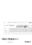
Thank you, and congratulations on your choice of the Roland Digital Piano RD-700SX.
SYRIA
SWITZERLAND
IRELAND
PERU
SAUDI ARABIA
SWEDEN
Roland Central Europe N.V.
Houtstraat 3, B-2260, Oevel
(Westerlo) BELGIUM
TEL: (014) 575811
FINLAND
Casa Veerkamp, s.a. de c.v.
Av. Toluca No. 323, Col. Olivar
de los Padres 01780 Mexico
D.F. MEXICO
TEL: (55) 5668-6699
Al Emadi Co. (Badie Studio &
Stores)
P.O. Box 62, Doha, QATAR
TEL: 4423-554
SPAIN
Roland Scandinavia A/S
Nordhavnsvej 7, Postbox 880,
DK-2100 Copenhagen
DENMARK
TEL: 3916 6200
MEXICO
QATAR
MuTek
Dorozhnaya ul.3,korp.6
117 545 Moscow, RUSSIA
TEL: (095) 981-4967
DENMARK
Gigamusic SARL
10 Rte De La Folie
97200 Fort De France
Martinique F.W.I.
TEL: 596 596 715222
TALENTZ CENTRE L.L.C.
Malatan House No.1
Al Noor Street, Ruwi
SULTANATE OF OMAN
TEL: 2478 3443
RUSSIA
Roland Elektronische
Musikinstrumente HmbH.
Austrian Office
Eduard-Bodem-Gasse 8,
A-6020 Innsbruck, AUSTRIA
TEL: (0512) 26 44 260
Owner’s Manual
OMAN
FBS LINES
Piata Libertatii 1,
535500 Gheorgheni,
ROMANIA
TEL: (266) 364 609
EUROPE
KUWAIT
6
*
03788712
’06-4-6N
202
Copyright © 2004 ROLAND CORPORATION
All rights reserved. No part of this publication may be reproduced in any form without the
written permission of ROLAND CORPORATION.
To resize thickness, move all items on the front cover
and center registration marks to left or right.
WARNING: To reduce the risk of fire or electric shock, do not expose this apparatus to rain or moisture.
CAUTION
RISK OF ELECTRIC SHOCK
DO NOT OPEN
ATTENTION: RISQUE DE CHOC ELECTRIQUE NE PAS OUVRIR
CAUTION: TO REDUCE THE RISK OF ELECTRIC SHOCK,
DO NOT REMOVE COVER (OR BACK).
NO USER-SERVICEABLE PARTS INSIDE.
REFER SERVICING TO QUALIFIED SERVICE PERSONNEL.
The lightning flash with arrowhead symbol, within an
equilateral triangle, is intended to alert the user to the
presence of uninsulated “dangerous voltage” within the
product’s enclosure that may be of sufficient magnitude to
constitute a risk of electric shock to persons.
The exclamation point within an equilateral triangle is
intended to alert the user to the presence of important
operating and maintenance (servicing) instructions in the
literature accompanying the product.
INSTRUCTIONS PERTAINING TO A RISK OF FIRE, ELECTRIC SHOCK, OR INJURY TO PERSONS.
IMPORTANT SAFETY INSTRUCTIONS
SAVE THESE INSTRUCTIONS
WARNING - When using electric products, basic precautions should always be followed, including the following:
1.
2.
3.
4.
5.
6.
7.
8.
9.
Read these instructions.
Keep these instructions.
Heed all warnings.
Follow all instructions.
Do not use this apparatus near water.
Clean only with a dry cloth.
Do not block any of the ventilation openings. Install in
accordance with the manufacturers instructions.
Do not install near any heat sources such as radiators,
heat registers, stoves, or other apparatus (including
amplifiers) that produce heat.
Do not defeat the safety purpose of the polarized or
grounding-type plug. A polarized plug has two blades with
one wider than the other. A grounding type plug has two
blades and a third grounding prong. The wide blade or the
third prong are provided for your safety. If the provided plug
does not fit into your outlet, consult an electrician for
replacement of the obsolete outlet.
10. Protect the power cord from being walked on or pinched
particularly at plugs, convenience receptacles, and the
point where they exit from the apparatus.
11. Only use attachments/accessories specified by the
manufacturer.
12. Use only with the cart, stand, tripod, bracket,
or table specified by the manufacturer, or
sold with the apparatus. When a cart is used,
use caution when moving the cart/apparatus
combination to avoid injury from tip-over.
13. Unplug this apparatus during lightning storms or when
unused for long periods of time.
14. Refer all servicing to qualified service personnel. Servicing
is required when the apparatus has been damaged in any
way, such as power-supply cord or plug is damaged, liquid
has been spilled or objects have fallen into the apparatus,
the apparatus has been exposed to rain or moisture, does
not operate normally, or has been dropped.
For the USA
DECLARATION OF CONFORMITY
Compliance Information Statement
Model Name :
Type of Equipment :
Responsible Party :
Address :
Telephone :
RD-700SX
Digital Piano
Roland Corporation U.S.
5100 S. Eastern Avenue, Los Angeles, CA 90040-2938
(323) 890-3700
For EU Countries
This product complies with the requirements of European Directives EMC 89/336/EEC and LVD 73/23/EEC.
For the USA
FEDERAL COMMUNICATIONS COMMISSION
RADIO FREQUENCY INTERFERENCE STATEMENT
For the U.K.
WARNING:
THIS APPARATUS MUST BE EARTHED
IMPORTANT: THE WIRES IN THIS MAINS LEAD ARE COLOURED IN ACCORDANCE WITH THE FOLLOWING CODE.
GREEN-AND-YELLOW: EARTH, BLUE: NEUTRAL, BROWN: LIVE
As the colours of the wires in the mains lead of this apparatus may not correspond with the coloured markings identifying
the terminals in your plug, proceed as follows:
The wire which is coloured GREEN-AND-YELLOW must be connected to the terminal in the plug which is marked by the
letter E or by the safety earth symbol or coloured GREEN or GREEN-AND-YELLOW.
The wire which is coloured BLUE must be connected to the terminal which is marked with the letter N or coloured BLACK.
The wire which is coloured BROWN must be connected to the terminal which is marked with the letter L or coloured RED.
This equipment has been tested and found to comply with the limits for a Class B digital device, pursuant to Part 15 of the
FCC Rules. These limits are designed to provide reasonable protection against harmful interference in a residential
installation. This equipment generates, uses, and can radiate radio frequency energy and, if not installed and used in
accordance with the instructions, may cause harmful interference to radio communications. However, there is no guarantee
that interference will not occur in a particular installation. If this equipment does cause harmful interference to radio or
television reception, which can be determined by turning the equipment off and on, the user is encouraged to try to correct the
interference by one or more of the following measures:
– Reorient or relocate the receiving antenna.
– Increase the separation between the equipment and receiver.
– Connect the equipment into an outlet on a circuit different from that to which the receiver is connected.
– Consult the dealer or an experienced radio/TV technician for help.
This device complies with Part 15 of the FCC Rules. Operation is subject to the following two conditions:
(1) This device may not cause harmful interference, and
(2) This device must accept any interference received, including interference that may cause undesired operation.
Unauthorized changes or modification to this system can void the users authority to operate this equipment.
This equipment requires shielded interface cables in order to meet FCC class B Limit.
For Canada
NOTICE
This Class B digital apparatus meets all requirements of the Canadian Interference-Causing Equipment Regulations.
AVIS
Cet appareil numérique de la classe B respecte toutes les exigences du Règlement sur le matériel brouilleur du Canada.
2
RD-700SX_e.book 3 ページ 2006年3月23日 木曜日 午後2時52分
USING THE UNIT SAFELY
The
symbol alerts the user to important instructions
or warnings.The specific meaning of the symbol is
determined by the design contained within the
triangle. In the case of the symbol at left, it is used for
general cautions, warnings, or alerts to danger.
Used for instructions intended to alert
the user to the risk of death or severe
injury should the unit be used
improperly.
Used for instructions intended to alert
the user to the risk of injury or material
damage should the unit be used
improperly.
* Material damage refers
other adverse effects
respect to the home
furnishings, as well
animals or pets.
The
symbol alerts the user to items that must never
be carried out (are forbidden). The specific thing that
must not be done is indicated by the design contained
within the circle. In the case of the symbol at left, it
means that the unit must never be disassembled.
to damage or
caused with
and all its
to domestic
The ● symbol alerts the user to things that must be
carried out. The specific thing that must be done is
indicated by the design contained within the circle. In
the case of the symbol at left, it means that the powercord plug must be unplugged from the outlet.
001
006
• Before using this unit, make sure to read the
instructions below, and the Owner’s Manual.
• When using the unit with a rack or stand recommended by Roland, the rack or stand must be
carefully placed so it is level and sure to remain
stable. If not using a rack or stand, you still need
to make sure that any location you choose for
placing the unit provides a level surface that will
properly support the unit, and keep it from
wobbling.
..........................................................................................................
..........................................................................................................
• Connect mains plug of this model to a mains
socket outlet with a protective earthing
connection.
..........................................................................................................
002b
• Do not open or perform any internal modifications on the unit. (The only exception would be
where this manual provides specific instructions
which should be followed in order to put in place
user-installable options; see p. 15 .)
..........................................................................................................
003
• Do not attempt to repair the unit, or replace parts
within it (except when this manual provides
specific instructions directing you to do so). Refer
all servicing to your retailer, the nearest Roland
Service Center, or an authorized Roland
distributor, as listed on the “Information” page.
..........................................................................................................
004
• Never use or store the unit in places that are:
• Subject to temperature extremes (e.g., direct
sunlight in an enclosed vehicle, near a heating
duct, on top of heat-generating equipment); or
are
• Damp (e.g., baths, washrooms, on wet floors);
or are
• Humid; or are
• Exposed to rain; or are
• Dusty; or are
• Subject to high levels of vibration.
..........................................................................................................
005
• This unit should be used only with a rack or stand
that is recommended by Roland.
008a
• The unit should be connected to a power supply
only of the type described in the operating
instructions, or as marked on the rear side of unit.
..........................................................................................................
008e
• Use only the attached power-supply cord. Also,
the supplied power cord must not be used with
any other device.
..........................................................................................................
009
• Do not excessively twist or bend the power cord,
nor place heavy objects on it. Doing so can
damage the cord, producing severed elements
and short circuits. Damaged cords are fire and
shock hazards!
..........................................................................................................
010
• This unit, either alone or in combination with an
amplifier and headphones or speakers, may be
capable of producing sound levels that could
cause permanent hearing loss. Do not operate for
a long period of time at a high volume level, or at
a level that is uncomfortable. If you experience
any hearing loss or ringing in the ears, you should
immediately stop using the unit, and consult an
audiologist.
..........................................................................................................
011
• Do not allow any objects (e.g., flammable
material, coins, pins); or liquids of any kind
(water, soft drinks, etc.) to penetrate the unit.
..........................................................................................................
..........................................................................................................
3
RD-700SX_e.book 4 ページ 2006年3月23日 木曜日 午後2時52分
012a
101a
• Immediately turn the power off, remove the
power cord from the outlet, and request servicing
by your retailer, the nearest Roland Service
Center, or an authorized Roland distributor, as
listed on the “Information” page when:
• The unit should be located so that its location or
position does not interfere with its proper ventilation.
..........................................................................................................
• The power-supply cord, or the plug has been
damaged; or
• If smoke or unusual odor occurs
• Objects have fallen into, or liquid has been
spilled onto the unit; or
• The unit has been exposed to rain (or otherwise
has become wet); or
• The unit does not appear to operate normally
or exhibits a marked change in performance.
..........................................................................................................
013
• In households with small children, an adult
should provide supervision until the child is
capable of following all the rules essential for the
safe operation of the unit.
..........................................................................................................
014
• Protect the unit from strong impact.
(Do not drop it!)
..........................................................................................................
015
• Do not force the unit’s power-supply cord to
share an outlet with an unreasonable number of
other devices. Be especially careful when using
extension cords—the total power used by all
devices you have connected to the extension
cord’s outlet must never exceed the power rating
(watts/amperes) for the extension cord. Excessive
loads can cause the insulation on the cord to heat
up and eventually melt through.
..........................................................................................................
016
• Before using the unit in a foreign country, consult
with your retailer, the nearest Roland Service
Center, or an authorized Roland distributor, as
listed on the “Information” page.
..........................................................................................................
022a
• Always turn the unit off and unplug the power
cord before attempting installation of the circuit
board (SRX Series; p. 15 ).
..........................................................................................................
023
• DO NOT play a CD-ROM disc on a conventional
audio CD player. The resulting sound may be of a
level that could cause permanent hearing loss.
Damage to speakers or other system components
may result.
..........................................................................................................
101c
• This (RD-700SX) for use only with Roland stand
KS-17. Use with other stands (or carts) is capable
of resulting in instability causing possible injury.
..........................................................................................................
102b
• Always grasp only the plug on the power-supply
cord when plugging into, or unplugging from, an
outlet or this unit.
..........................................................................................................
103a
• At regular intervals, you should unplug the
power plug and clean it by using a dry cloth to
wipe all dust and other accumulations away from
its prongs. Also, disconnect the power plug from
the power outlet whenever the unit is to remain
unused for an extended period of time. Any
accumulation of dust between the power plug
and the power outlet can result in poor insulation
and lead to fire.
..........................................................................................................
104
• Try to prevent cords and cables from becoming
entangled. Also, all cords and cables should be
placed so they are out of the reach of children.
..........................................................................................................
106
• Never climb on top of, nor place heavy objects on
the unit.
..........................................................................................................
107b
• Never handle the power cord or its plugs with
wet hands when plugging into, or unplugging
from, an outlet or this unit.
..........................................................................................................
108a
• Before moving the unit, disconnect the power
plug from the outlet, and pull out all cords from
external devices.
..........................................................................................................
109a
• Before cleaning the unit, turn off the power and
unplug the power cord from the outlet (p. 23 ).
..........................................................................................................
110a
• Whenever you suspect the possibility of lightning
in your area, pull the plug on the power cord out
of the outlet.
..........................................................................................................
115a
• Install only the specified circuit board(s) (SRX
Series). Remove only the specified screws (p. 15 ).
026
• Do not put anything that contains water (e.g.,
flower vases) on this unit. Also, avoid the use of
insecticides, perfumes, alcohol, nail polish, spray
cans, etc., near the unit. Swiftly wipe away any
liquid that spills on the unit using a dry, soft
cloth.
..........................................................................................................
4
..........................................................................................................
118a
• Should you remove the screws fastening the
board slot cover, keep them in a safe place out of
children’s reach, so there is no chance of them
being swallowed accidentally.
..........................................................................................................
RD-700SX_e.book 5 ページ 2006年3月23日 木曜日 午後2時52分
IMPORTANT NOTES
291b
In addition to the items listed under “IMPORTANT SAFETY INSTRUCTIONS” and “USING THE UNIT SAFELY” on pages 3
and 4, please read and observe the following:
Power Supply
301
• Do not connect this unit to same electrical outlet that is being
used by an electrical appliance that is controlled by an inverter
(such as a refrigerator, washing machine, microwave oven, or air
conditioner), or that contains a motor. Depending on the way in
which the electrical appliance is used, power supply noise may
cause this unit to malfunction or may produce audible noise. If it
is not practical to use a separate electrical outlet, connect a power
supply noise filter between this unit and the electrical outlet.
307
• Before connecting this unit to other devices, turn off the power to
all units. This will help prevent malfunctions and/or damage to
speakers or other devices.
308
• Although the LCD and LEDs are switched off when the POWER
switch is switched off, this does not mean that the unit has been
completely disconnected from the source of power. If you need
to turn off the power completely, first turn off the POWER
switch, then unplug the power cord from the power outlet. For
this reason, the outlet into which you choose to connect the
power cord’s plug should be one that is within easy reach and
readily accessible.
Placement
351
• Using the unit near power amplifiers (or other equipment
containing large power transformers) may induce hum. To
alleviate the problem, change the orientation of this unit; or
move it farther away from the source of interference.
352a
• This device may interfere with radio and television reception. Do
not use this device in the vicinity of such receivers.
352b
• Noise may be produced if wireless communications devices,
such as cell phones, are operated in the vicinity of this unit. Such
noise could occur when receiving or initiating a call, or while
conversing. Should you experience such problems, you should
relocate such wireless devices so they are at a greater distance
from this unit, or switch them off.
354a
• Do not expose the unit to direct sunlight, place it near devices
that radiate heat, leave it inside an enclosed vehicle, or otherwise
subject it to temperature extremes. Excessive heat can deform or
discolor the unit.
355b
• When moved from one location to another where the temperature and/or humidity is very different, water droplets (condensation) may form inside the unit. Damage or malfunction may
result if you attempt to use the unit in this condition. Therefore,
before using the unit, you must allow it to stand for several
hours, until the condensation has completely evaporated.
358
• Do not allow objects to remain on top of the keyboard. This can
be the cause of malfunction, such as keys ceasing to produce
sound.
402
• Never use benzine, thinners, alcohol or solvents of any kind, to
avoid the possibility of discoloration and/or deformation.
Repairs and Data
452
• Please be aware that all data contained in the unit’s memory may
be lost when the unit is sent for repairs. Important data should
always be backed up in another MIDI device (e.g., a sequencer),
or written down on paper (when possible). During repairs, due
care is taken to avoid the loss of data. However, in certain cases
(such as when circuitry related to memory itself is out of order),
we regret that it may not be possible to restore the data, and
Roland assumes no liability concerning such loss of data.
Additional Precautions
551
• Please be aware that the contents of memory can be irretrievably
lost as a result of a malfunction, or the improper operation of the
unit. To protect yourself against the risk of loosing important
data, we recommend that you periodically save a backup copy of
important data you have stored in the unit’s memory in another
MIDI device (e.g., a sequencer).
552
• Unfortunately, it may be impossible to restore the contents of
data that was stored in another MIDI device (e.g., a sequencer)
once it has been lost. Roland Corporation assumes no liability
concerning such loss of data.
553
• Use a reasonable amount of care when using the unit’s buttons,
sliders, or other controls; and when using its jacks and
connectors. Rough handling can lead to malfunctions.
554
• Never strike or apply strong pressure to the display.
556
• When connecting / disconnecting all cables, grasp the connector
itself—never pull on the cable. This way you will avoid causing
shorts, or damage to the cable’s internal elements.
557
• A small amount of heat will radiate from the unit during normal
operation.
558a
• To avoid disturbing your neighbors, try to keep the unit’s
volume at reasonable levels. You may prefer to use headphones,
so you do not need to be concerned about those around you
(especially when it is late at night).
559a
• When you need to transport the unit, package it in the box
(including padding) that it came in, if possible. Otherwise,
you will need to use equivalent packaging materials.
561
• Use only the specified expression pedal (EV-5/7; sold
separately). By connecting any other expression pedals, you risk
causing malfunction and/or damage to the unit.
Handling CD-ROMs
801
Maintenance
401a
• For everyday cleaning wipe the unit with a soft, dry cloth or one
that has been slightly dampened with water. To remove
stubborn dirt, use a cloth impregnated with a mild, non-abrasive
detergent. Afterwards, be sure to wipe the unit thoroughly with
a soft, dry cloth.
• Avoid touching or scratching the shiny underside (encoded
surface) of the disc. Damaged or dirty CD-ROM discs may not be
read properly. Keep your discs clean using a commercially
available CD cleaner.
5
RD-700SX_e.book 6 ページ 2006年3月23日 木曜日 午後2時52分
Main Features
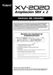
Progressive Hammer Action
Rhythm and Arpeggiator Functions
The RD-700SX incorporates Roland’s “progressive hammer action
keyboard,” which realistically reproduces the comfortable, natural
touch of the grand piano. While offering excellent responsiveness
and quiet action, this keyboard also reproduces the subtle changes in
touch as you move from the lower to the higher registers.
Additionally, the progressive hammer action keyboard features an
environmentally friendly design, with absolutely no lead used in the
hammers.
You can play back Rhythm patterns and perform arpeggios with the
press of a single button.
Enjoy a variety of performance techniques, with backing using
realistic drum sounds for a real session feel, arpeggios and cutting
you get just by playing the chords, and more (p. 46,p. 48).
New Piano Tones
The instrument features newly developed, authentic piano tones
with wide dynamic range and rich expression. Great for any musical
genre or scene, whether it be performing with a band or playing a
solo ballad, the RD-700SX is the perfect stage piano.
Additionally, The instrument features an 88-note multisampled
piano painstakingly recorded by professional engineers. It boasts not
only tonal quality but also a high level of presence, making it closer
than ever to the “real thing.”
It is also furnished with a wealth of electronic piano, organ, string,
synth pad, and other Tones that allow you to use the instrument as a
stage piano. Once you try it onstage, you'll come to fully understand
its capabilities.
Fast MIDI Control
You can also control various functions, such as adjusting volume
levels and selecting Tones, simply and easily from an external MIDI
device. This provides fast and intuitive control when using the
keyboard on stage (p. 60).
Interface for Full Connectivity
The RD-700SX comes equipped with a USB port for connecting to
computers. You can use this to perform with MIDI data received
from the computer and to save the RD-700SX’s setup files.
Additionally, two separate MIDI OUT ports allow you to control two
different MIDI sound modules simultaneously.
On top of all this, the RD-700SX XLR connectors provide balanced
output to connected audio gear, enabling you to supply stable audio
output.
Exclusive Piano Functions
Expandability
The “Piano Edit” function allows you to program subtle changes for
the piano and electric piano tones (p. 73).
You can install up to two Wave Expansion Boards, a favorite for use
with Roland’s SRX Series.
Starting with the “SRX-02 Concert Grand” Tone, you can enjoy
performing with the most up-to-date Tones available as they are
continually released (p. 15).
A Full 128 Voices
The RD-700SX features 128-voice polyphony, with all sounds
available in every performance mode. Enjoy natural performances
even when layering multiple sounds.
Simple Push-Button Operation
You can access Split, Effects and carry out other main operations
simply by pressing a single button (p. 12).
Furthermore, pressing the ONE TOUCH [PIANO] button lets you
immediately switch to the settings most suited for piano
performances, regardless of the mode or settings currently in effect
(p. 32).
High-Quality Effects
In addition to two multi-effects systems, you can also use the reverb
and chorus individually. The instrument also realistically
reproduces the tonal changes of an acoustic grand piano, including
the change in resonance created by pressing the damper pedal (p. 75)
and the degree of openness of the grand piano’s lid (p. 74).
Moreover, the Sound Control function (p. 44) and digital equalizer
(p. 45) enable a wide range of tonal adjustments.
Equipped With Organ Tone Wheel
Sound Generator
For organ Tones, the RD-700SX comes equipped with an organ Tone
wheel sound generator used in the Roland Combo Organ. This
sound generator lets you recreate organ sounds, changing the level
of each footage (p. 54).
6
Sophisticated Design
With its black body, the RD-700SX offers the perfect look and
presence on stage. The panel’s refined design enhances operability,
while rear cable connections are a cinch.
In addition, the cover to the wave expansion board is designed so it
won’t easily fall off even if the screws are removed.
SMF Play Function
The RD-700SX is compatible with both General MIDI and General
MIDI 2 standards. Additionally, you can transmit SMF music files to
the RD-700SX from the USB port and play back the data. This allows
you to perform while playing back SMF music files without the use
of an external sequencer.
Convention Used in This Manual
• Words enclosed in square brackets [ ] indicate panel buttons.
Example: [SPLIT] indicates the SPLIT button.
• (p. **) indicates a reference page
• The explanations in this manual include illustrations that depict
what should typically be shown by the display. Note, however,
that your unit may incorporate a newer, enhanced version of
the system (e.g., includes newer sounds), so what you actually
see in the display may not always match what appears in the
manual.
RD-700SX_e.book 7 ページ 2006年3月23日 木曜日 午後2時52分
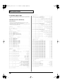
Contents
USING THE UNIT SAFELY............................................................................................................................... 3
IMPORTANT NOTES......................................................................................................................................... 5
Main Features..........................................................................................6
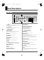
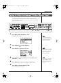
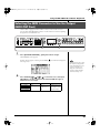
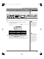
Panel Descriptions................................................................................12
Front Panel ......................................................................................................................................................... 12
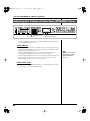
Rear Panel........................................................................................................................................................... 14
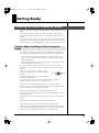
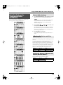
Getting Ready........................................................................................15
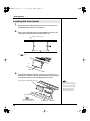
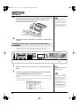
Installing the Wave Expansion Board ............................................................................................................ 15
Cautions When Installing an Wave Expansion Board..................................................................... 15
Installing SRX Series Boards ................................................................................................................ 16
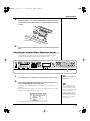
Checking the Installed Wave Expansion Boards .............................................................................. 17
Installation de la carte d’extension Wave(French language for Canadian Safety Standard)................. 18
Precautions lors de l’installation de la carte d’extension Wave ..................................................... 18
Installer les cartes de serie SRX ........................................................................................................... 19
Verification des cartes d’extension audio apres installation........................................................... 20
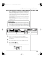
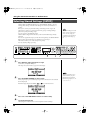
Connecting the RD-700SX to External Equipment ....................................................................................... 21
Connecting Pedals................................................................................................................................. 22
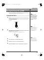
Turning the Power On and Off ....................................................................................................................... 23
Turning On the Power .......................................................................................................................... 23
Turning Off the Power.......................................................................................................................... 24
Adjusting the Volume....................................................................................................................................... 24
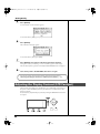
Restoring the Factory Settings (Factory Reset).............................................................................................. 25
Adjusting the Display Contrast (LCD Contrast) .......................................................................................... 26
Tuning to Other Instruments’ Pitches (Master Tune) .................................................................................. 27
Overview of the RD-700SX ...................................................................28
Basic Organization of the RD-700SX .............................................................................................................. 28
Units of Sound ................................................................................................................................................... 28
Basic Operation.................................................................................................................................................. 28
Main Screens .......................................................................................................................................... 28
Special Indications................................................................................................................................. 29
About the Function Buttons................................................................................................................. 29
About the CURSOR Buttons ................................................................................................................ 30
Changing the Settings Values.............................................................................................................. 30
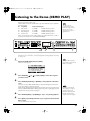
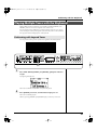
Listening to the Demo (DEMO PLAY) .................................................31
Performing with the Keyboard.............................................................32
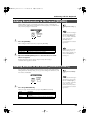
Piano Performances (ONE TOUCH) .............................................................................................................. 32
Performing with a Variety of Tones ............................................................................................................... 33
Specifying the Tone Number to Select a Tone ([NUM LOCK])...................................................... 34
Selecting Wave Expansion Board Tones ............................................................................................ 35
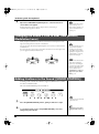
Playing Multiple Tones with the Keyboard .................................................................................................. 37
Performing with Layered Tones ......................................................................................................... 37
Playing Different Tones in Two Different Sections of the Keyboard ([SPLIT]) ........................... 38
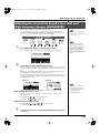
Changing the Tone for a Zone............................................................................................................. 40
Adjust the Volume Level for Individual Zones (ZONE SWITCH/ZONE LEVEL Slider)..................... 41
Transposing the Key of the Keyboard ([TRANSPOSE]).............................................................................. 42
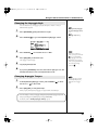
Adding Reverberation to the Sound ([REVERB])......................................................................................... 43
Adding Breadth to the Sound ([CHORUS/DELAY]).................................................................................. 43
Changing the Sound’s Pitch in Real Time (Bender/Modulation Lever)................................................... 44
Adding Liveliness to the Sound ([SOUND CONTROL])............................................................................ 44
Adjusting the Level of the Sound’s Low, Mid, and High-Frequency Ranges ([EQUALIZER])............ 45
7
RD-700SX_e.book 8 ページ 2006年3月23日 木曜日 午後2時52分
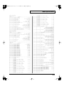
Contents
Using the Convenient Functions in Performances............................46
Playing Arpeggios ([ARPEGGIO]) ................................................................................................................. 46
Changing the Arpeggio Style .............................................................................................................. 47
Changing Arpeggio Tempos................................................................................................................ 47
Playing Rhythm ([RHYTHM/SONG]) .......................................................................................................... 48
Changing the Rhythm Pattern............................................................................................................. 49
Changing Rhythm Tempos.................................................................................................................. 49
Playing the Songs ([RHYTHM/SONG])........................................................................................................ 50
Selecting the Song.................................................................................................................................. 51
Changing Song Tempos ....................................................................................................................... 51
Applying Effects to the Sound (Multi-Effects).............................................................................................. 52
Simulating the Creation of Organ Tones (Tone Wheel Mode) ................................................................... 53
Changing the Undulation of the Organ Tone (Rotary Effect)......................................................... 54
Changing the ZONE LEVEL Slider Feet Assignments (Harmonic Bar) ....................................... 54
Disabling the Button (Panel Lock) .................................................................................................................. 55
Selecting Stored Settings ([SETUP])................................................................................................................ 56
Registering the Setups You Like (Favorite Setups) .......................................................................... 57
Storing Settings to Setups ([WRITE]) ............................................................................................................. 58
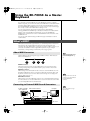
Using the RD-700SX As a Master Keyboard.......................................60
What’s MIDI? ..................................................................................................................................................... 60
About MIDI Connectors ....................................................................................................................... 60
Connecting to External MIDI Sound Generators.............................................................................. 60
Selecting the MIDI Connector to Use for Output (MIDI OUT Port).......................................................... 61
MIDI Send Channel Settings............................................................................................................................ 62
Selecting Sounds on an External MIDI Device.............................................................................................. 63
Adjusting the Volume of Each Zone (EXTERNAL Zone) ........................................................................... 64
Detailed Settings for Transmitted Parts (EXTERNAL) ....................................................................... 65
How to Make Settings .................................................................................................................. 65
Adjusting the Volume and Pan (Volume/Pan) ........................................................................ 65
Setting the Amount of Reverb and Chorus (Reverb/Chorus) ............................................... 65
Playing Sound Monophonically (Mono/Poly)......................................................................... 66
Setting the Transposition for Each Individual Zone (Transpose).......................................... 66
Setting the Key Range (Key Range Lower/Upper) ................................................................. 66
Changing the Range That Plays in Response to the Velocity
(Velocity Range Lower/Upper) .................................................................................................. 66
Changing Tone Elements (ATK/DCY/REL/COF/RES)........................................................ 66
Smoothly Changing the Pitch (Portamento) ............................................................................. 67
Setting the Change in Volume According to the Force Used to Play the Keyboard
(Velocity Sensitivity/Max) .......................................................................................................... 67
Changing the Pitch (Coarse Tune/Fine Tune).......................................................................... 67
Setting the Range for the Change in Pitch with the Bender (Bend Range)........................... 67
Setting the Amount of Modulation Applied (Modulation Depth) ........................................ 67
Turning Each Controller On and Off ......................................................................................... 67
Transmitting the Control Change (USER CC/USER CC Value) ........................................... 67
Making Detailed Settings for Tones ....................................................68
Making Zone Settings (Zone Info) .................................................................................................................. 68
How to Make Settings........................................................................................................................... 68
Selecting the Tone.................................................................................................................................. 68
Setting the Volume and Pan (Volume/Pan)...................................................................................... 68
Setting the Zone to Which Multi-effects Are Applied (MFX1/MFX2 Source)............................. 68
Setting the Transposition for Each Individual Zone (Transpose) .................................................. 69
Setting the Key Range for Each Zone (Key Range) .......................................................................... 69
Setting the Change in Volume According to the Force Used to Play the Keyboard
(Velocity Range/Sens/Max)................................................................................................................ 69
Assigning Internal Parts to INTERNAL Zone (Part Assign) .......................................................... 69
Turning the Controllers in Each Zone On and Off........................................................................... 70
8
RD-700SX_e.book 9 ページ 2006年3月23日 木曜日 午後2時52分
Contents
Making Tone Settings (Tone Info)................................................................................................................... 70
How to Make Settings........................................................................................................................... 70
Selecting the Part and the Tone to Be Set (Part, Tone) ..................................................................... 71
Setting the Reverb/Chorus Depth (Reverb/Chorus Amount) ...................................................... 71
Changing the Effect Applied to the Tone (MFX Type) .................................................................... 71
Playing Sound Monophonically (Mono/Poly) ................................................................................. 71
Changing the Pitch (Coarse Tune/Fine Tune).................................................................................. 71
Creating Smooth Pitch Changes (Portamento Switch/Time)......................................................... 71
Changing Tone Elements (Attack Time/Release Time/Cutoff/Resonance/Decay Time)........ 72
Changing the Bend Range (Bend Range)........................................................................................... 72
Making Detailed Settings for the ONE TOUCH Tones .......................73
Making Detailed Settings for the Piano Tones (Piano Edit)........................................................................ 73
Making the settings ............................................................................................................................... 73
Selecting the Piano Sound .................................................................................................................... 73
Changing the Width of the Sound (Stereo Width) ........................................................................... 73
Changing the Sound’s Nuance (Nuance)........................................................................................... 73
Changing the Sense of Space Surrounding the Sound (Ambience)............................................... 73
Changing the Amount of Reverb Effect (Reverb Level) .................................................................. 73
Opening/Closing the Piano Lid (Lid) ................................................................................................ 74
Changing the Characteristics of the Mic (Mic Type/Distance)...................................................... 74
Adjusting the Resonant Sounds When the Keys are Pressed (String Resonance)....................... 74
Making the Midrange Equalizer Settings (EQ SW/EQ Gain/EQ Frequency/EQ Q)................. 74
Changing the Key Touch (Key Touch)............................................................................................... 74
Making Fine Adjustments to the Keyboard Touch (Key Touch Offset)........................................ 75
Setting a Constant Volume Level in Response to the Playing Force (Velocity)........................... 75
Changing the Timing of Sounds in Response to the Velocity (Velocity Delay Sens).................. 75
Changing the Touch Sensitivity According to the Key Range (Velocity Keyfollow Sens)......... 75
Finely Adjusting the Tuning (Micro Tune)........................................................................................ 75
Adjusting Resonance when the Damper Pedal is Depressed (Sympathetic Resonance)............ 75
Changing Sound Characteristics (Tone Modify) .............................................................................. 76
Restore the settings to initial conditions (Initialize)......................................................................... 76
Making Detailed Settings for the E.Piano Tones (E.Piano Edit)................................................................. 76
Making the settings ............................................................................................................................... 76
Selecting the E.Piano Sound................................................................................................................. 77
Selecting the Amp Type(AMP Type).................................................................................................. 77
Applying Effects to the Sound (Effect Type/Depth/Rate) ............................................................. 77
Making the Midrange Equalizer Settings (EQ-SW/EQ Gain/EQ Frequency/EQ Q) ................ 77
Changing Sound Characteristics (Tone Modify) .............................................................................. 77
Detailed Settings for Each Function ([EDIT]) .....................................78
Parameters That Can Be Set ............................................................................................................................. 78
Setting Parameters................................................................................................................................. 79
Making System Settings (System)................................................................................................................... 79
How to Make Settings........................................................................................................................... 79
Adjusting the Volume (Master Volume)............................................................................................ 80
Preventing Equalizer Settings from Being Switched (EQ Mode)................................................... 80
Preventing Pedal Settings from Being Switched (Pedal Mode)...................................................... 80
Retaining the Current Tone Even When Tones Are Switched (Tone Remain) ............................ 81
Changing the Clock (Timing) Source (Clock Source) ...................................................................... 81
Transmitting Synchronization Messages (Clock Out) ..................................................................... 81
Using Program Change Messages to Switch Setups (SETUP Control Channel) ......................... 81
Setting the Device ID Number (Device ID) ....................................................................................... 81
Switching the Pedal’s Polarity (Pedal/FC1/FC2 Polarity) ............................................................. 81
Selecting the Display Appearance (Display Mode).......................................................................... 82
Selecting the Number of Parts (Part Mode)....................................................................................... 82
Setting the Tuning Method (Temperament/Key) ............................................................................ 82
Precise Modification of Chord Sonorities (Stretch Tune) ................................................................ 82
Switching Between Reception of GM/GM2 System On and GS Reset ......................................... 82
Setting the Keyboard Touch (Key Touch)...................................................................................................... 83
9
RD-700SX_e.book 10 ページ 2006年3月23日 木曜日 午後2時52分
Contents
How to Make Settings........................................................................................................................... 83
Changing the Key Touch (Key Touch)............................................................................................... 83
Making Fine Adjustments to the Keyboard Touch (Key Touch Offset)........................................ 83
Setting a Constant Volume Level in Response to the Playing Force (Velocity)........................... 84
Changing the Timing of Sounds in Response to the Velocity (Velocity Delay Sens).................. 84
Changing the Touch Sensitivity According to the Key Range (Velocity Keyfollow Sens)......... 84
Pedal and MULTI EFFECTS [CONTROL] Knob Settings (Control).......................................................... 84
How to Make Settings........................................................................................................................... 84
Assigning Functions to Pedals (FC1/FC2 Pedal Assign) ................................................................ 85
Changing the MULTI EFFECTS [CONTROL] Knob Settings (Control Knob Assign)................ 85
Changing the Slider Settings (Slider Assign) .................................................................................... 85
Setting the Multi-Effects, Reverb, and Chorus Effects (Effects) ................................................................. 86
How to Make Settings........................................................................................................................... 86
Making Multi-Effects Settings ............................................................................................................. 86
Making Reverb Settings........................................................................................................................ 87
Setting Chorus and Delay .................................................................................................................... 88
Making the Sound Control Settings (Sound Control).................................................................................. 88
How to Make Settings........................................................................................................................... 88
Selecting the Type of Compressor (Sound Control Type)............................................................... 89
Detailed Settings of Compressor......................................................................................................... 89
Managing Setup Files (File Utility/USB)....................................................................................................... 89
Saving Setup Files to the Memory (Save SETUP File) ..................................................................... 89
Calling Up Setup Files from Memory (Load SETUP File)............................................................... 90
Deleting Files from Memory (File Delete) ......................................................................................... 91
Setting MIDI Receive Parts (Part Parameter) ................................................................................................ 91
How to Make Settings........................................................................................................................... 91
Selecting the Part to Be Set (Part/Tone)............................................................................................. 92
Setting the Receive Channel (Receive Channel) ............................................................................... 92
Setting the Volume and Pan (Volume/Pan)...................................................................................... 92
Setting the Required Polyphony (Voice Reserve)............................................................................. 92
Preventing Parts from Being Played (Part Switch)........................................................................... 92
Making the Effect ON/OFF Settings (MFX Switch)......................................................................... 92
Setting Reception and Blocking of MIDI Messages from External MIDI Controllers................. 92
Making the Rhythm and Arpeggio Settings (Rhythm/Arpeggio) ............................................................ 93
How to Make Settings........................................................................................................................... 93
Making the rhythm Settings ................................................................................................................ 93
Making Arpeggio Settings ................................................................................................................... 95
About V-LINK ................................................................................................................................................... 97
Connection Examples ........................................................................................................................... 97
Turning the V-Link ON/OFF .............................................................................................................. 97
V-Link Settings....................................................................................................................................... 97
Detailed Settings of V-Link .................................................................................................................. 98
Other Functions (Utility) .................................................................................................................................. 98
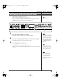
Transferring the RD-700SX’s Settings to an External MIDI Device (Bulk Dump)....................... 98
Restoring the settings to the factory condition (Factory Reset).................................................... 100
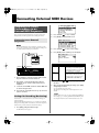
Connecting External MIDI Devices....................................................101
Recording RD-700SX Performances to an External MIDI Sequencer ...................................................... 101
Connecting to an External Sequencer............................................................................................... 101
Settings for Recording (Rec Setting) ................................................................................................. 101
Recording the Performance................................................................................................................ 102
Exiting Rec Mode................................................................................................................................. 102
About the Local Switch....................................................................................................................... 102
Playing the RD-700SX’s Internal Sound Generator from an External MIDI Device ............................. 103
Making Connections ........................................................................................................................... 103
Setting the Channels ........................................................................................................................... 103
Selecting RD-700SX Sounds from an External MIDI Device......................................................... 103
Switching Setups ................................................................................................................................. 103
Switching Tones................................................................................................................................... 103
10
RD-700SX_e.book 11 ページ 2006年3月23日 木曜日 午後2時52分
Contents
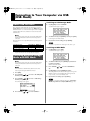
Connecting to Your Computer via USB (USB Mode).......................104
About USB Functions...................................................................................................................................... 104
Switching Between Storage Mode and MIDI Mode................................................................................... 104
Exchanging Files with Computers (Storage Mode).................................................................................... 105
Connections.......................................................................................................................................... 105
Cautions Regarding Folders and Files ............................................................................................. 105
Exchanging Files.................................................................................................................................. 105
Exiting Storage Mode.......................................................................................................................... 105
Exchanging MIDI Messages with Your Computer (MIDI Mode)............................................................ 106
Switching USB Drivers ................................................................................................................................... 106
Appendices..........................................................................................108
Troubleshooting............................................................................................................................................... 108
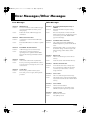
Error Messages/Other Messages .................................................................................................................. 111
Error Messages..................................................................................................................................... 111
Other Messages.................................................................................................................................... 111
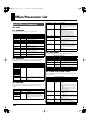
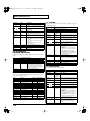
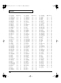
Effect/Parameter List...................................................................................................................................... 112
Multi-Effects Parameter...................................................................................................................... 112
Chorus Parameter................................................................................................................................ 144
Reverb Parameter ................................................................................................................................ 145
Tone List ........................................................................................................................................................... 146
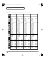
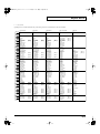
Rhythm Set List................................................................................................................................................ 149
Arpeggio Style List.......................................................................................................................................... 152
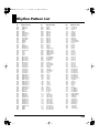
Rhythm Pattern List ........................................................................................................................................ 153
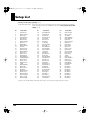
Setup List .......................................................................................................................................................... 154
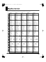
Shortcut List ..................................................................................................................................................... 155
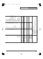
MIDI Implementation..................................................................................................................................... 156
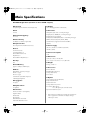
Main Specifications ......................................................................................................................................... 172
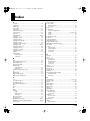
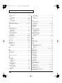
Index.................................................................................................................................................................. 173
Purpose-Oriented Index ................................................................................................................................. 178
Volume Setting..................................................................................................................................... 178
Key Touch and Velocity ..................................................................................................................... 178
Equalizer ............................................................................................................................................... 178
Pitch and Tuning ................................................................................................................................. 178
Effects (Reverb, Chorus, Multi-Effects)............................................................................................ 178
Control .................................................................................................................................................. 178
Key Range............................................................................................................................................. 178
11
RD-700SX_e.book 12 ページ 2006年3月23日 木曜日 午後2時52分
Panel Descriptions
Front Panel
fig.buttons
1
3
2
4
5
1. [V-LINK]
[CHORUS/DELAY]
Switching this on lets you control external V-LINK compatible video
equipment connected to the RD-700SX (p. 97).
Changes the chorus type (p. 43).
MULTI-EFFECTS [CONTROL] knob
2. VOLUME Slider
Adjusts the way that effects are applied (p. 52).
Adjusts the overall volume that is output from the rear panel
OUTPUT jacks and PHONES jack (p. 24).
MULTI-EFFECTS [ON/OFF]
3. EQUALIZER/EFFECTS
[SOUND CONTROL]
Switches the multi-effects on/off (p. 52).
5. ZONE SWITCH/CONTROL
Switching this on reduces inconsistencies in the volume and
produces a more stable, coherent sound (p. 44).
ZONE SWITCH
[LOW] knob
ZONE LEVEL slider
Adjusts the sound’s low-frequency range (p. 45).
Adjusts the volume level for each part (p. 41).
[MID FREQ] knob
When [EXTERNAL/INTERNAL] is on, this controls each part for
the external MIDI sound generator (p. 64).
Adjusts the midrange frequencies (p. 45).
[MID LEVEL] knob
Adjusts the sound’s midrange-frequency range (p. 45).
[HIGH] knob
Adjusts the sound’s high-frequency range (p. 45).
[ON/OFF]
Turns the equalizer on/off (p. 45).
4. REVERB, CHORUS/DELAY, MULTI-EFFECTS
REVERB [DEPTH] knob
Adjusts the amount of reverb (p. 43).
[REVERB]
Changes the reverb type (p. 43).
CHORUS/DELAY [DEPTH] knob
Adjusts the amount of chorus (p. 43).
12
Turns each part’s sound on and off (p. 41).
In addition, when [CONTROL/ZONE LEVEL] is on, the tone is
changed in real time in response to the assigned parameter and
function.
[EXTERNAL/INTERNAL]
Puts the RD-700SX in control of the external MIDI sound generator
(p. 60).
[RHYTHM/SONG]
Switches RHTYHM and SONG on/off (p. 48, p. 50).
[CONTROL/ZONE LEVEL]
This determines the function of the ZONE LEVEL sliders (p. 85).
[ARPEGGIO]
Switches Arpeggiator on/off (p. 46).
[SPLIT]
Puts the keyboard in “Split mode,” wherein you can use more than
one tone by having different tones play in different parts of the
keyboard (p. 38).
RD-700SX_e.book 13 ページ 2006年3月23日 木曜日 午後2時52分
Panel Descriptions
fig.buttons
6
8
7
10
12
11
9
13
14
[TRANSPOSE]
[SETUP]
Sets the range of the keyboard to transposed (p. 42).
Calls up the stored settings (Setup) (p. 56).
6. DISPLAY
11. ZONE SELECT buttons
This shows the Tone names and the values of various settings, etc.
Selects the zone for which the tone is to be selected (p. 40).
[SHIFT/EXIT]
12. EXPANSION [A], [B]
Pressed to return to a previous screen or to cancel a procedure that is
in progress.
This selects a sound from a wave expansion board, sold separately
(p. 35).
Additionally, you can easily call up Edit screens for related
parameters for the following functions by holding down this button
while pressing buttons, turning knobs, or operating other controllers
(p. 155).
13. FUNCTION
[EDIT]
Press this button when you wish to adjust various settings (p. 78).
[F1/TONE INFO]
[WRITE]
This allows you to change the tone settings (p. 70).
Stores the current settings to “Setup” (p. 58).
You can also use this to assign functions in some screens.
[NUM LOCK]
[F2/ZONE INFO]
This allows you to change the zone settings (p. 68).
You can also use this to assign functions in some screens.
[ENTER]
This is used to finalize a value or execute an operation.
7. CONTRAST knob
], [
In addition, you can listen to the demo songs by simultaneously
pressing this button and [EDIT] (DEMO PLAY) (p. 31).
14. TONE SELECT buttons
Pressed to select tones (p. 33).
Adjusts the display’s contrast (p. 26).
8. CURSOR [
You can input numerical values with the TONE SELECT buttons
when this button is lit (p. 34).
], [
], [
]
Press these to switch pages and to move the cursor.
You can also input numerical values with these buttons when the
[NUM LOCK] button is on. [NUM LOCK] turns on automatically in
the Edit and other screens, enabling input of numerical values with
the buttons.
fig.Bender
9. [DEC], [INC]
This is used to modify values.
If you keep on holding down one button while pressing the other,
the value change accelerates.
10. ONE TOUCH
Pitch Bend/Modulation Lever
[PIANO]
This allows you to control pitch bend or apply vibrato (p. 44).
Selects the optimum settings for piano performances (p. 32).
[E.PIANO]
Selects the optimum settings for E.piano performances (p. 32).
13
RD-700SX_e.book 14 ページ 2006年3月23日 木曜日 午後2時52分
Panel Descriptions
Rear Panel
fig.rear
1
3
4
2
1. [POWER ON] Switch
Switch turns the power on/off (p. 23).
2. AC Inlet
Connect the included power cord to this inlet (p. 21).
3. Wave Expansion Board Installation Slot
Remove the cover for installation of optional wave expansion boards
(SRX Series) (p. 15).
4. USB Connector
Connect your computer here to exchange Standard MIDI file and
setup file between the computer and the RD-700SX (p. 104).
5. PEDAL Jacks (DAMPER, FC1, FC2)
Connecting the pedal switch (DP series) provided with the RD700SX to the DAMPER jack allows you to use the switch as a damper
pedal.
With a pedal connected to the FC-1 or FC-2 jack, you can then assign
a variety of functions to the pedal (p. 70, p. 84).
6. MIDI Connectors (IN, OUT1, OUT2, THRU)
Used for connecting external MIDI devices and for transmission of
MIDI messages (p. 60, p. 91, p. 101).
7. OUTPUT L (MONO)/R Jacks
Provide output of the audio signals. These are connected to an amp
or other device. For monaural output use the L/MONO jack (p. 21).
8. BALANCED OUT L/R Jacks
Connectors for balanced output of the audio signals. Connect to
mixers and other such gear (p. 21).
9. PHONES Jack
A set of headphones can be connected to this jack (p. 21).
Even when headphones are connected, sound will still be output
from the OUTPUT jacks.
14
5
6
7
8
9
RD-700SX_e.book 15 ページ 2006年3月23日 木曜日 午後2時52分
Getting Ready
Installing the Wave Expansion Board
Up to two optional Wave Expansion Boards (SRX Series) can be installed in the RD700SX.
Wave Expansion Boards store Wave data, Patches, and Rhythm Sets, and by
equipping the RD-700SX with these boards, you can greatly expand your sound
palette.
For more information about the wave expansion board tones, refer to the patch list
included with the wave expansion board. However, some of the tone names may be
displayed differently on the RD-700SX. Check 36page as you refer to the tone names.
Cautions When Installing an Wave Expansion
Board
901
• To avoid the risk of damage to internal components that can be caused by static
electricity, please carefully observe the following whenever you handle the board.
1
• Before you touch the board, always first grasp a metal object (such as a water
pipe), so you are sure that any static electricity you might have been carrying
has been discharged.
2
• When handling the board, grasp it only by its edges. Avoid touching any of the
electronic components or connectors.
• Use a Philips screwdriver that is suitable for the size of the screw (a number 2
screwdriver). If an unsuitable screwdriver is used, the head of the screw may be
stripped.
• To remove a screw, rotate the screwdriver counterclockwise. To tighten a screw, rotate the screwdriver
clockwise.
loosen
tighten
• Be careful that the screws you remove do not drop into
the interior of the RD-700SX.
• Do not leave the rear panel cover removed. After installation of the Wave
Expansion Boards is complete, be sure to replace the cover.
911
• Do not touch any of the printed circuit pathways or connection terminals.
912
• Never use excessive force when installing a circuit board. If it doesn’t fit properly
on the first attempt, remove the board and try again.
913
• When circuit board installation is complete, double-check your work.
914
• Always turn the unit off and unplug the power cord before attempting installation
of the circuit board.
915
• Install only the specified circuit board(s) (SRX Series). Remove only the specified
screws.
• Be careful not to cut your hand on the edge of the installation bay.
Install the Wave Expansion Boards after removing the rear panel cover.
There are two slots (A and B) into which a board can be installed. Specify which slot’s
board is to be used by pressing EXPANSION [A] or [B] on the front panel when
using waves, tones, or Rhythm Sets from the wave expansion boards.
15
RD-700SX_e.book 16 ページ 2006年3月23日 木曜日 午後2時52分
Getting Ready
Installing SRX Series Boards
1
2
Before installing any Wave Expansion Board, turn off the power on
the RD-700SX and all devices connected to it.
Refer to the following illustration of the RD-700SX’s rear panel, and
remove the screws indicated. Then, remove the cover.
fig.00-02e
Screws to be removed
You can remove the cover easily by pressing on the lower part of the cover (above
the
mark).
fig.00-03e
push
3
Insert the Wave Expansion Board connector into a connector for an
SRX Series slot (SRX A or SRX B), while simultaneously inserting the
board holders into the holes in the Wave Expansion Board.
fig.00-04e
Wave Expansion Board (SRX series)
If the same type of Wave
Expansion Board is installed in
the SRX A slot and the SRX B
slot, it will only be possible to
select data from the Wave
Expansion Board that was
installed in the SRX A slot.
Board holder
Position them as shown
before you install the board.
16
Connector
RD-700SX_e.book 17 ページ 2006年3月23日 木曜日 午後2時52分
Getting Ready
4
Use the Installation Tool supplied with the Wave Expansion Board to
turn the holders in the LOCK direction, so the board will be fastened
in place.
fig.00-05e
LOCK
Installation tool
5
Use the screws that you removed in step 2 to fasten the cover back in
place.
Checking the Installed Wave Expansion Boards
After installation of the Wave Expansion Boards has been completed, check to
confirm that the installed boards are being recognized correctly.
fig.00-06p
2
1
2
Turn on the power, as described in “Turning On the Power” (p. 23).
“Selecting Wave Expansion
Board Tones” (p. 35).
The name of the installed wave expansion board is displayed for as
long as EXPANSION [A] or [B] is held down.
The number of tones and Rhythm Sets contained in the expansion board is
displayed.
The example here depicts what you would see if the SRX-02 “Concert Piano” Wave
Expansion Board were installed in the SRX A slot.
fig.00-07g
If “------” appears next to the
name of the slot in which the
board was installed, it may be
that the wave expansion board
is not being recognized
properly. Use the procedure in
“Turning Off the Power” (p.
24) to turn the power off, then
reinstall the wave expansion
board correctly.
By releasing the button, you go back to the previous screen.
17
RD-700SX_e.book 18 ページ 2006年3月23日 木曜日 午後2時52分
Getting Ready
Installation de la carte d’extension Wave(French
language for Canadian Safety Standard)
Vous pouvez installer jusqu’a 2 cartes d’extension optionnelles dans le RD-700SX.
Ces cartes d’extension memorisant des donnees Wave, des morceaux et des
ensembles rythmiques, elles vous permettront d’augmenter considerablement le
timbre.
Pour de plus amples renseignements sur les tonalités de la carte d'expansion Wave,
se reporter à la liste des timbres incluse avec la carte. Toutefois, certains des noms de
tonalités peuvent s'afficher différemment sur le RD-700SX. Consulter la p. 36 pour
les noms des tonalités.
Precautions lors de l’installation de la carte
d’extension Wave
901(F)
• Veuillez suivre attentivement les instructions suivantes quand vous manipulez la
carte afin d’éviter tout risque d’endommagement des pièces internes par
l’électricité statique.
1
• Toujours toucher un objet métallique relié à la terre (comme un tuyau par
exemple) avant de manipuler la carte pour vous décharger de l’électricité
statique que vous auriez pu accumuler.
2
• Lorsque vous manipulez la carte, la tenir par les côtés. Évitez de toucher aux
composants ou aux connecteurs.
• Utiliser un tournevis cruciforme correspondant a la taille de la vis (un tournevis
numero 2). En cas d’utilisation d’un tournevis inapproprie, la tete de la vis pourrait
etre endommagee.
• Pour enlever les vis, tourner le tournevis dans le sens contraire des aiguilles d’une
montre. Pour resserrer, tourner dans le sens des aiguilles d’une montre.
fig.00-01f
• Veillez a ne pas laisser tomber de vis dans le chassis
du RD-700SX.
desserrer
resserrer
• Ne pas laisser la plaque arriere detachee. Apres
avoir installe la ou les carte(s) d’extension, bien
remettre la plaque en place.
911(F)
• Ne pas toucher aux circuits imprimés ou aux connecteurs.
912(F)
• Ne jamais forcer lors de l’installation de la carte de circuits imprimés. Si la carte
s’ajuste mal au premier essai, enlevez la carte et recommencez l’installation.
913(F)
• Quand l’installation de la carte de circuits imprimés est terminée, reverifiez si tout
est bien installé.
914(F)
• Toujours éteindre et debrancher l’appareil avant de commencer l’installation de la
carte.
915(F)
• N’installez que les cartes de circuits imprimes specifiees (SRX Series). Enlevez
seulement les vis indiquees.
• Installer les cartes d’extension apres avoir enleve la plaque arriere.
• Veillez a ne pas vous couper les doitgs sur le bord de l’ouverture d’installation.
Avant d'installer la carte d'expansion Wave, retirer le panneau arrière.
Il y a deux emplacements (A et B) dans lesquels une carte peut être installée. Spécifier
l'emplacement à utiliser en appuyant sur EXPANSION [A] ou [B] sur le panneau
avant lors de l'utilisation d'ondes, de tons ou de groupes rythmiques à partir des
cartes d'expansion Wave.
18
RD-700SX_e.book 19 ページ 2006年3月23日 木曜日 午後2時52分
Getting Ready
Installer les cartes de serie SRX
1
2
Avant d’installer une carte d’extension Wave, eteindre tous les
appareils relies au RD-700SX.
Detacher la plaque arriere en enlevant les vis indiquees sur le schema
suivant.
fig.00-02f
Vis à enlever
Il est facile d’enlever le couvercle: il suffit d’appuyer sur la partie inférieure du
couvercle (au-dessus du symbole
).
fig.00-03f
push
3
Inserer le connecteur de la carte dans un des creneaux pour la serie
SRX (SRX A, SRX B) tout en enfoncant les supports a carte dans les
trous de celle-ci.
fig.00-04f
Carte d'extension Wave (serie SRX)
Support à carte
Avant l’installation, orienter les supports
à carte tel qu’indiqué sur le schéma.
Connecteur
19
RD-700SX_e.book 20 ページ 2006年3月23日 木曜日 午後2時52分
Getting Ready
4
Pour tourner les supports en position LOCK (verrouille), utilisez l’outil
d’installation de la carte d’extension fournie a cet effet. De cette
facon, la carte sera bien fixee a sa place.
fig.00-05f
LOCK
Si la meme sorte de carte
d’extension Wave est installee
dans les creneaux SRX A et
SRX B, il ne sera possible de
selectionner que les donnees
de la carte d’extension Wave
installee dans le creneau SRX
A.
Outil d'installation
5
Reposez le couvercle en remettant les vis enlevees (comme specifie)
a l’etape 2.
Verification des cartes d’extension audio apres
installation
Lorsque l’installation des cartes d’extension audio est terminee, proceder a une
verification pour s’assurer que l’ordinateur les identifie correctement.
fig.00-06p
2
1
2
Mettre sous tension de la facon decrite sous “Turning On the Power”
(p. 23).
Le nom de la carte d'expansion Wave installée s'affiche tant que la
touche EXPANSION [A] ou [B] est tenue enfoncée.
Le nombre de tonalités et de groupes rythmiques compris sur la carte d'expansion
s'affiche.
L’exemple montre ce qui serait affiche si la carte d’extension audio SRX-02 “Concert
Piano”etait installee dans la fente SRX A.
fig.00-07g
Lorsque vous le relacherez, vous serez ramene a l’ecran precedent.
20
“Selecting Wave Expansion
Board Tones” (p. 35).
Si “----------------” est affiche a
cote du nom de la fente dans
laquelle la carte est installee, il
est possible que la carte
d’extension audio installee ne
soit pas reconnue
correctement. Mettre hors
tension de la facon decrite sous
“Turning Off the Power” (p.
24) et reinstaller correctement
la carte d’extension audio.
RD-700SX_e.book 21 ページ 2006年3月23日 木曜日 午後2時52分
Getting Ready
Connecting the RD-700SX to External Equipment
The RD-700SX is not equipped with an amplifier or speakers. In order to produce
sound, you need to hook up audio equipment such as a monitor speaker or a stereo
set, or use headphones.
* Audio cables, MIDI cables, USB cables, headphones, and expression pedals are not included.
Consult your Roland dealer if you need to purchase accessories such as these.
To prevent malfunction and/
or damage to speakers or other
devices, always turn down the
volume, and turn off the
power on all devices before
making any connections.
921
fig.00-08e
to Power outlet
Computer
Expression pedal (EV-5/7)
or Pedal switch (DP-2/8)
Pedal switch
(DP-2/8)
Stereo
headphones
MIDI IN
MIDI IN
MIDI OUT
Monitor speakers
(powered)
MIDI sound module etc.
V-LINK-compatible
video equipment.
Mixer etc.
MIDI sequencer etc.
Power amp.
21
RD-700SX_e.book 22 ページ 2006年3月23日 木曜日 午後2時52分
Getting Ready
1
Before you begin making connections, confirm the following.
Is the volume level of the RD-700SX or connected amp turned all the way down?
Is the power to the RD-700SX or connected amp turned off?
2
Connect supplied power cord to the RD-700SX, and plug the other end
into an AC power outlet.
Use Stereo headphones.
3
Connect the RD-700SX and the external device.
Use audio cables to connect audio equipment, such as an amp or speakers. Use MIDI
cables to connect MIDI devices. Use USB cables to connect computer.
If you are using headphones, plug them into the PHONES jack.
Connect pedal switches or expression pedals as necessary.
Connecting Pedals
Use only the specified
expression pedal (EV-5/7; sold
separately). By connecting any
other expression pedal, you
risk causing malfunction and/
or damage to the unit.
5
Connect the pedal included with the RD-700SX to one of the PEDAL jacks.
When connected to the DAMPER jack, the pedal can be used as a damper pedal.
Connecting the pedal to the FC-1 or FC-2 jack allows you to assign a variety of
functions to the pedal (p. 70, p. 85).
About the Output Jacks
922
This instrument is equipped with balanced (XLR) type jacks. Wiring diagrams for
these jacks are shown below. Make connections after first checking the wiring
diagrams of other equipment you intend to connect.
fig.XLRJack
22
Set the switch on the included
pedal to “Continuous” when
the pedal is connected.
RD-700SX_e.book 23 ページ 2006年3月23日 木曜日 午後2時52分
Getting Ready
Turning the Power On and Off
941
Once the connections have been completed, turn on power to your various devices
in the order specified. By turning on devices in the wrong order, you risk causing
malfunction and/or damage to speakers and other devices.
Turning On the Power
1
Before you switch on the power, move the volume down all the way by
moving the VOLUME Slider.
Also completely turn down the volume of any connected audio device and other
equipment.
In the unlikely event the
power is turned off or cut off
while Factory Reset (p. 22) is
in progress, the data may
become corrupted, and it
may require additional time
for the unit to start up the
next time.
fig.00-09
2
Press the upper portion of the [POWER ON] switch on the back of the
RD-700SX to turn on the power.
To prevent incorrect
functioning of the Pitch Bend/
Modulation Lever (p. 44),
refrain from touching the lever
while the power to the RD700SX is turned on.
The unit is powered up, and the display’s backlighting comes on.
fig.00-10
3
4
5
Turn on the power to connected external devices.
Adjust the volume of the connected external device.
This unit is equipped with a
protection circuit. A brief
interval (a few seconds) after
power up is required before
the unit will operate normally.
942
Adjust the RD-700SX’s volume to obtain the proper volume level.
23
RD-700SX_e.book 24 ページ 2006年3月23日 木曜日 午後2時52分
Getting Ready
Turning Off the Power
1
Before you switch on the power, move the volume down all the way by
moving the VOLUME Slider.
Also completely turn down the volume of any connected audio device and other
equipment.
2
3
Turn off the power to connected external devices.
Press the lower portion of the [POWER ON] switch on the back of the
RD-700SX.
The power is switched off.
Adjusting the Volume
fig.00-11
1
Adjust the volume using the VOLUME slider.
Move the slider up to increase the volume, or down to lower it.
Also adjust the volume of the connected device to an appropriate level.
24
If you need to turn off the
power completely, first turn
off the POWER switch, then
unplug the power cord from
the power outlet.
Refer to “Power Supply” (p.
5).
RD-700SX_e.book 25 ページ 2006年3月23日 木曜日 午後2時52分
Getting Ready
Restoring the Factory Settings (Factory Reset)
When using the RD-700SX for the first time, start by returning the settings to their
factory defaults so that the RD-700SX operates as described in the procedures in the
owner’s manual.
Notes
Never turn off the power during Factory Reset (while “Now, Executing”
appears in the display).
Turning off the power while Factory Reset is in progress may result in
corrupted internal data and may prevent the power from being turned on again. If
you have confirmed that the internal data has been lost, or if a similar problem exists,
consult the retailer from whom you purchased the instrument, or the nearest Roland
Service Center. Note, however, that Roland assumes no liability, including
compensation, for consequences arising from any loss of data.
Executing this operation
deletes the Setup settings (p.
56). If you want to keep any
internally stored content, use
the “Bulk Dump (Bulk Dump
SETUP)” procedure to save the
data to an external sequencer
(p. 99).
When making USB
connections, be absolutely
sure to disconnect the USB
cable before starting.
fig.00-12p
3,5,6,7
1
2,4
1
Press [EDIT], getting the indicator to light.
The Edit Menu screen appears.
fig.00-13g
Instead of selecting with the
CURSOR, you can press TONE
SELECT [9] to display the
Utility Edit screen directly.
2
3
Press CURSOR [
] to select “9.Utility.”
Press [ENTER] to display the Utility screen.
fig.00-14g
4
Press CURSOR [
] to select “Factory Reset All.”
25
RD-700SX_e.book 26 ページ 2006年3月23日 木曜日 午後2時52分
Getting Ready
5
Press [ENTER].
A screen like the one shown below appears.
fig.00-15g
To cancel the Factory Reset, press [EXIT].
6
Press [ENTER].
The confirmation message appears.
fig.00-16g
To cancel the Factory Reset, press [EXIT].
7
Press [ENTER] once again to start the Factory Reset operation.
During the execution, “Executing... Don’t Power OFF” appears in the display.
After the Factory Reset operation is finished, the ONE TOUCH screen will appear.
8
Turn off the power to the RD-700SX, then turn it on again.
You can also restore only part of the setting to their factory status. Refer to
“Restoring the settings to the factory condition (Factory Reset)” (p. 100).
Adjusting the Display Contrast (LCD Contrast)
The characters in the display may be difficult to view immediately after turning on
the power or after extended use; this may also be because of where and how the
display is situated.
In such instances, adjust the display contrast by turning the CONTRAST knob on the
front panel.
fig.00-17p
26
RD-700SX_e.book 27 ページ 2006年3月23日 木曜日 午後2時52分
Getting Ready
Tuning to Other Instruments’ Pitches (Master Tune)
For a cleaner ensemble sound while performing with one or more other instruments,
ensure that each instrument’s basic pitch is in tune with that of the other
instruments. In general, the tuning of an instrument is indicated by the pitch in Hertz
(Hz) of the middle “A” note.
This matching of other instruments’ basic reference pitches is called “tuning.”
fig.00-18ps
3
1
5
2,4
1,6
Press [EDIT], getting the indicator to light.
The Edit Menu screen appears.
fig.00-19g
2
3
Press CURSOR [
You can directly display the
System Edit screen by pressing
TONE SELECT [0] instead of
selecting with CURSOR.
] to select “0.System.”
Press [ENTER] to display the Edit screen.
fig.00-20g
4
5
6
Press CURSOR [
parameter.
] to move the cursor to the “Master Tune”
Press [INC]/[DEC] to select the value (415.3–440.0–466.2).
For faster value increases, keep
[INC] pressed down and press
[DEC]. For decreasing value
faster, keep [DEC] pressed
down and press [INC].
If you want to save this setting,
press [F1(WRITE)]. Settings
saved in the RD-700SX are not
deleted even when the power
is turned off.
Press [EDIT] to make the indicator go dark.
You are returned to the Tone screen.
27
RD-700SX_e.book 28 ページ 2006年3月23日 木曜日 午後2時52分
Overview of the RD-700SX
Basic Organization of the
RD-700SX
The RD-700SX can be divided into two sections: a keyboard
controller section and a sound generator section. The two
sections are connected internally by means of MIDI.
fig.00-G01e
Sound
Generator
Section
Play
Keyboard Controller Section
(controllers such as keyboard, pitch bend lever, etc.)
Keyboard Controller Section
This section includes the keyboard, the Pitch Bend/Modulation
Lever, the panel knobs, the sliders, and any pedal connected to
the rear panel. Actions such as pressing and releasing of keys on
the keyboard, depressing a pedal, and so forth, are converted to
MIDI messages and sent to the sound generator section, or to an
external MIDI device.
Sound Generator Section
The sound generator section produces the sound. Here, MIDI
messages received from the keyboard controller section or
external MIDI device are converted to musical signals, which are
then output as analog signals from the OUTPUT and PHONES
jacks.
Units of Sound
When using the RD-700SX, you will notice that a variety of
different categories come into play when working with sounds.
What follows is a simple explanation of each sound category.
Tone
The individual sounds used when playing the RD-700SX are
referred to as “Tones.” The RD-700SX provides 488 types of
Tones. Tones are assigned to each part.
The Tones also include various groups of percussion instrument
assembled into “Rhythm Sets.” Each key (note number) of a
Rhythm Set will produce a different percussion instrument.
28
Part
A sound generator of this type which can control multiple
sounds using one device is referred to as a multitimbral sound
generator. The RD-700SX contains a multitimbral sound
generator capable of playing sixteen Tones simultaneously.
“Parts” are where Tones that are created when the RD-700SX is
used as a sound generator are assigned. Since different Tones
can be assigned to each of the Parts and controlled individually,
you can have multiple Tones play simultaneously, divide the
keyboard into separate ranges and have different Tones sound
in the different parts (Split), and enjoy playing ensemble
performances.
The sixteen Parts played by the RD-700SX’s internal sound
generator are referred to as “Internal Parts.”
Zone
The RD-700SX features four Parts (UPPER1, UPPER2, LOWER1,
and LOWER2) that you can use for freely controlling the Internal
Parts with the RD-700SX’s buttons and keyboard. These four
Parts that are used for controlling the Internal Parts are
collectively known as the “INTERNAL Zone.” Four of the
sixteen Internal Parts are assigned to the INTERNAL Zone for
control (the RHYTHM Part is fixed at Part 10).
Furthermore, you can freely control external MIDI sound
generators with the RD-700SX in the same manner as with the
INTERNAL Zone. You can likewise control the external MIDI
sound generator with the four Parts (UPPER1, UPPER2,
LOWER1, and LOWER2), with this group of four Parts being
referred to as the “EXTERNAL Zone.” The external MIDI sound
generator is assigned to these three Parts for control (the
RHYTHM Part can also be partially set).
Basic Operation
Main Screens
ONE TOUCH Screen
When ONE TOUCH [PIANO] or [E.PIANO] is pressed, setting
the RD-700SX to the optimal status for piano performances, this
screen is displayed.
fig.00-G03g
RD-700SX_e.book 29 ページ 2006年3月23日 木曜日 午後2時52分
Overview of the RD-700SX
The Tone Screen (Basic Screen)
fig.00-G06g
The names of the Tones currently selected for the INTERNAL
Zone are displayed. This is the screen that is ordinarily
displayed.
You can change the INTERNAL Zone (UPPER1, UPPER2,
LOWER1, and LOWER2) Tones and tempo.
fig.00-G02g
The Tone Wheel Screen
In the Tone screen, when any ORGAN Tone “Tone Wheel 1-10”
is selected for any of the INTERNAL Zone, this screen is
displayed when CURSOR [
] is pressed. The mode when this
screen is displayed is called “Tone Wheel mode,” and while in
this mode you can simulate the creation of sounds using an
organ’s harmonic bars (p. 53).
EXTERNAL Screen
When [EXTERNAL/INTERNAL] is pressed, the button’s
indicator lights up, and the RD-700SX switches to the mode
enabling it to control an external MIDI sound generator. The
status of this button determines whether the RD-700SX’s buttons
are used to control the INTERNAL Zone ([EXTERNAL/
INTERNAL] unlit), or to control the EXTERNAL Zone
([EXTERNAL/INTERNAL] lit).
In addition, you can make detailed settings for the MIDI
messages to be transmitted to the external sound generator (p.
61).
fig.00-G06g
Pressing CURSOR [
] when this screen is displayed returns
you to the Tone screen.
fig.00-G04g
Special Indications
fig.mark-tempoM
A mark is displayed to the right of the tone name when
you select an 88-key multisampled piano tone in the
Tone screen.
The Setup Screen
fig.mark-tempoM
A mark is displayed to the left of the tone name when
you select “TW-Organ 1–10” in the Tone screen.
The currently selected Setup is displayed (p. 56).
Pressing CURSOR [
] when the Tone screen or Tone Wheel
Screen is displayed switches the RD-700SX to this screen. You
can also have this screen displayed by pressing [SETUP]. You
can change the Setups (p. 46, p. 48, p. 50).
Pressing CURSOR [
] while this mark is displayed
brings up the Tone Wheel screen (p. 53).
fig.mark-tempoM
Pressing CURSOR [
] when this screen is displayed returns
you to the Tone screen or Tone Wheel Screen.
With Clock Source (p. 81) set to MIDI, the tempo
indication changes to “M:” for each screen.
The tempo can be changed with the external MIDI
devices when this mark is indicated.
fig.00-G05g
fig.mark-EQ
With EQ Mode (p. 80) set to SYSTEM, this mark
appears upper right on the screen.
Equalizer settings do not change when Setups are
switched while this mark is indicated.
fig.mark-PD
With Pedal Mode (p. 80) set to “SYSTEM,” this mark
appears on the upper right of the screen.
Pedal settings do not change when Setups are switched
while this mark is indicated.
The Rhythm/Song/Arpeggio Screen
Pressing CURSOR [
] when the Tone screen is displayed
switches the RD-700SX to this screen.
You can change Song, Rhythm patterns, Arpeggio patterns, and
the tempo.
About the Function Buttons
fig.00-G07p
Pressing CURSOR [
] when this screen is displayed returns
you to the Tone screen.
29
RD-700SX_e.book 30 ページ 2006年3月23日 木曜日 午後2時52分
Overview of the RD-700SX
[EDIT]
By pressing [EDIT] to make the indicator light, you can enter
“Edit mode.” In Edit mode you can make detailed settings for
various functions.
You can exit Edit mode by pressing [EDIT], extinguishing its
indicator.
Additionally, when multiple parameters are presented
horizontally in a row, as shown in the EXTERNAL screen, you
can get the cursor to move more rapidly by holding down the
CURSOR button that points in the direction you want the cursor
to move while you also press the CURSOR button that points in
the opposite direction.
fig.00-G11pj
[WRITE]
Stores the current settings to “Setup” (p. 58).
[NUM LOCK]
When [NUM LOCK] is pressed, the button’s indicator lights up,
enabling input of numerical values using the TONE SELECT
buttons. The button indicators automatically light according to
the values set.
Changing the Settings Values
About the CURSOR Buttons
fig.00-G12p
fig.00-G08p
The CURSOR buttons are used for switching screens, and for
moving to an item whose setting you want to change (by
moving the cursor).
Moving Between Display Pages
When arrow symbols (“ ” and “ ”) appear at the upper right of
the display screen, it indicates that there are additional pages in
the directions shown by the arrows.
You can switch screens with CURSOR [
] and [
].
fig.00-G09g
When changing settings values, you can use [DEC] and [INC], or
the TONE SELECT buttons (numeric keys).
[DEC], [INC]
Pressing [INC] increases the value, and [DEC] decreases it. Keep
the button pressed for continuous adjustment. For faster value
increases, keep [INC] pressed down and press [DEC]. For
decreasing value faster, keep [DEC] pressed down and press
[INC].
Simultaneously pressing [DEC] and [INC] sets that parameter to
the standard default value or switches it off.
TONE SELECT Buttons
(Numeric Keys)
Navigating Among Items To Be Set
(CURSOR)
When more than one parameter is present in a screen, the name
and value of the parameter to be changed is shown with a box
around it. This box is referred to as the “cursor.” The cursor is
moved with the CURSOR buttons.
fig.00-G10g
Cursor
30
When [NUM LOCK] is on (lit), numerical values can be input
directly using the TONE SELECT buttons, which then serve as
[0]–[9] numeric keys. When you enter the number, the value will
blink. This indicates that the value has not yet been finalized. To
finalize the value press [ENTER].
With some parameters, [NUM LOCK] may come on
automatically, allowing you to input numerical values directly
with the TONE SELECT buttons.
Only numerical values can be entered using the numeric keys.
To switch the positive (+) or negative (-) signs for numerical
values and make continuous changes in the numerical values,
press [INC] or [DEC].
RD-700SX_e.book 31 ページ 2006年3月23日 木曜日 午後2時52分
Listening to the Demo (DEMO PLAY)
Here’s how to listen to these songs.
The RD-700SX features the internal demo songs that exhibit the special capabilities
of the instrument.
No. Song Name
Composer/Copyright
01.
Take a Break
Scott Tibbs
© 2004 Roland Corporation
02.
Superior Grand
Scott Tibbs
© 2004 Roland Corporation
03.
Everything Cool
Scott Tibbs
© 2004 Roland Corporation
04.
Tone Preview
Scott Tibbs
© 2004 Roland Corporation
All rights reserved.
Unauthorized use of this
material for purposes other
than private, personal
enjoyment is a violation of
applicable laws.
981a
Demo song 04 “Tone Preview” makes effective use of the internal tones. A total of
ten pieces are offered, one for each TONE CATEGORY.
fig.Q1-01p
4,5
3
2
1
* When demo songs are playing back, all settings are switched to their status at the time the
RD-700SX’s power was turned on. Store any arrangements of settings that you want to keep
in Setup (p. 58).
1
Hold down [NUM LOCK] and press [EDIT].
The Demo screen appears.
fig.Q1-02g
No data for the music that is
played will be output from the
MIDI OUT connector.
982
2
3
Press CURSOR [
you wish to hear.
]/[
] or [INC] / [DEC] to select the song that
Press CURSOR [F2(PLAY)] or [ENTER] to start playback of the demo
song.
Press any one of the TONE SELECT buttons, and playback begins from the demo
song corresponding to the button pressed.
When all songs have been played, playback will return to the first song and resume.
Pressing a TONE SELECT button during playback stops the song being played, and
playback of the newly selected song begins.
4
5
Press CURSOR [EXIT] or [F1(MENU)] to stop a song during playback.
Regardless of whether the
song is playing or stopped,
pressing ONE TOUCH
[PIANO] or [E.PIANO] ends
the demo and returns the
original screen to the display.
Press [EXIT] or [F1(EXIT)] while the song is stopped to finish with the
Demo screen.
You are returned to the Tone screen.
31
RD-700SX_e.book 32 ページ 2006年3月23日 木曜日 午後2時52分
Performing with the Keyboard
Piano Performances (ONE TOUCH)
Now, try performing with the piano.
With the RD-700SX, you can call up the optimal settings for piano performances with
the press of a single button.
You can also select your preferred tones and settings and store them to the
instrument’s buttons.
fig.Q1-03p
2
1
1
Press ONE TOUCH [PIANO] or [E.PIANO].
fig.Q1-04g
Pressing ONE TOUCH [PIANO] sets the entire keyboard to play with the piano
tone.
Pressing ONE TOUCH [E.PIANO] sets the entire keyboard to play with the electric
piano tone.
2
Pressing ONE TOUCH
[PIANO] or [E.PIANO]
restores all of the settings
except for the Piano Edit(p. 73)
or Electric Piano Edit(p. 76)
settings to their status at the
time the power was turned on.
If you want to preserve these
settings, record them to a
setup(p. 56).
You can now press [F1] to switch the type.
Pressing [F1] toggles you between Types A and B.
fig.Q1-05g
You can use CURSOR [
]/
[
] in the ONE TOUCH
(PIANO) screen to adjust the
amount the grand piano lid is
opened.
With the RD-700SX, you can also make more detailed settings to make the sound
even better match your favorite piano performances. You can store a total of four
settings configurations, two each to [PIANO] and [E.PIANO].
Please refer to each as needed.
• Fine Adjustment of Piano Tones (Piano Edit) →p. 73
• Fine Adjustment of E.Piano Tones (E.Piano Edit) →p. 76
• Fine Adjustment of the Piano Touch Sense →p. 74
32
RD-700SX_e.book 33 ページ 2006年3月23日 木曜日 午後2時52分
Performing with the Keyboard
Performing with a Variety of Tones
The RD-700SX provides 488 types of Tones.
Each one of these individual sounds is called a “tone.”
Tones are assigned to the TONE SELECT buttons according to the tone category
selected.
“Tone List” (p. 146)
Try selecting and performing with a number of different tones.
fig.Q1-06p
1
1
3
Press ONE TOUCH [PIANO] or [E.PIANO].
This selects a single tone to be played over the entire keyboard.
2
Press any of the TONE SELECT buttons to select the tone category.
The TONE SELECT button for the selected category lights.
3
2
If multiple tones are playing,
do not press the ONE TOUCH
[PIANO] button, but instead
select the zone containing the
tone to be changed using the
ZONE SELECT buttons. Refer
to “Changing the Tone for a
Zone” (p. 40).
Press [INC]/[DEC] to select the tone.
Play the keyboard, and you will hear the selected tone.
The next time you choose this TONE SELECT button, the tone you’re selected here
is played.
If [NUM LOCK] is turned on,
the Tone Category cannot be
selected with TONE SELECT
button. For details, refer to p.
34.
Tones selected with [RHY/
GM2] are registered in the
following order: “Rhythm
Sets,” “GM2 Rhythm Sets,”
and “GM2 Tones.” Refer to the
“Tone List” (p. 146).
33
RD-700SX_e.book 34 ページ 2006年3月23日 木曜日 午後2時52分
Performing with the Keyboard
Specifying the Tone Number to Select a Tone
([NUM LOCK])
Each individual tone has a different tone number.
You can select tones with the TONE SELECT buttons by inputting numerals with
these buttons to specify tone numbers.
“Tone List” (p. 146)
Turn [NUM LOCK] on when inputting numerals with the TONE SELECT buttons.
fig.Q1-07p
4 1
1
Press [NUM LOCK] to make the indicator light.
This enables input of numerals with the TONE SELECT buttons.
The numerical value that can be entered with each button is indicated beneath the
buttons.
3
4
2
Press ONE TOUCH [PIANO] or [E.PIANO].
This selects a single tone to be played over the entire keyboard.
2
3
If multiple tones are playing,
do not press the ONE TOUCH
[PIANO] button, but instead
select the zone containing the
tone to be changed using the
ZONE SELECT buttons. Refer
to “Changing the Tone for a
Zone” (p. 40).
Enter the tone number with the TONE SELECT buttons.
Press [ENTER].
The tone is set.
Play the keyboard, and you will hear the selected tone.
The TONE SELECT buttons included in the selected Tone numbers lit.
Playing a Rhythm Set
Among the tones that can be selected with the TONE SELECT buttons are Rhythm
Sets, which are collections of a variety of percussion instrument sounds and special
sound effects. Here’s how to select a Rhythm Set and play percussion sounds.
1. Press ONE TOUCH [PIANO] or [E.PIANO].
2. Press TONE SELECT [RHY/GM2].
If [NUM LOCK] is turned on at this time, the Rhythm Set Category cannot be
selected. Turn [NUM LOCK] off.
3. Press different keys to play different percussion instruments.
4. To select a different Rhythm Set, press [INC]/[DEC].
The combination of sounds assigned to the keyboard varies according to the
Rhythm set. Refer to “Rhythm Set List” (p. 149).
34
Tones selected with [RHY/
GM2] are registered in the
following order: “Rhythm
Sets,” “GM2 Rhythm Sets,”
and “GM2 Tones.” Refer to the
“Rhythm Set List” (p. 149).
RD-700SX_e.book 35 ページ 2006年3月23日 木曜日 午後2時52分
Performing with the Keyboard
Selecting Wave Expansion Board Tones
Up to two optional wave expansion boards (SRX series) can be installed into the RD700SX.
Use the following procedure when selecting tones stored on an wave expansion
board.
fig.Q1-08p
1 4
1
Press ONE TOUCH [PIANO] or [E.PIANO].
This selects a single tone to be played over the entire keyboard.
2
2
3
For instructions on installing
the Expansion Board, refer to
“Installing the Wave
Expansion Board” (p. 15).
Press EXPANSION [A] or [B] to make its indicator light.
fig.Q1-09g
If you hold down EXPANSION [A] or [B] for several seconds, the name of the
installed wave expansion board appears in the display (p. 17).
3
4
Press [NUM LOCK] to turn on the button indicator.
Press [INC]/[DEC], or press the TONE SELECT buttons to select the
Tone.
When using the TONE SELECT buttons to input Tone numbers, press [ENTER]
afterwards to set the number.
5
For more on the wave
expansion board tone lists,
refer to “Patch List” (for RD700) and “Rhythm Set List”
(for RD-700) in the SRX Series
Owner's Manuals. However,
some of the tone names may be
displayed differently on the
RD-700SX. Refer to “Wave
Expansion Board Tone
Name Correspondence
Table” (p. 36).
Play the keyboard, and you will hear the selected tone.
35
RD-700SX_e.book 36 ページ 2006年3月23日 木曜日 午後2時52分
Performing with the Keyboard
Selecting Tones Without Pressing [NUM LOCK]
You can select tones stored on expansion boards with [NUM LOCK] off.
1. Press EXPANSION [A] or [B] to make its indicator light.
2. Use the TONE SELECT buttons and [DEC]/[INC] to select the tone.
Wave expansion board tones are assigned to the TONE SELECT buttons as
shown below.
fig.Q1-10e
Tone
Number
001 011 021 031 041 051 061 071 081 Rhythm
Set
:
:
:
:
:
:
:
:
:
010 020 030 040 050 060 070 080 090
091
:
100
101
:
3. Play the keyboard, and you will hear the selected tone.
Wave Expansion Board Rhythm Set Tone Numbers
When selecting a Wave Expansion Board Rhythm Set with the RD-700SX, the Wave
Expansion Board Rhythm Sets are placed after Patches (called Tones on the RD700SX).
Thus, when you want to specify a Wave Expansion Board Rhythm Set in terms of a
Tone number, the Tone number can be arrived at by adding the desired Rhythm Set
number in the Rhythm Set List to the last Patch number in the Patch List.
Wave Expansion Board Tone Name Correspondence Table
The RD-700SX displays certain SRX Series tone names as shown below. There may
be displayed differently from Owner’s Manuals of SRX series.
SRX-03
(STUDIO SRX)
No.
Tone Name
005
Taxi EP
021
US EP
022
Studio EP
023
All EP
024
Sens. EP
36
SRX-05
(Supreme Dance)
No.
Tone Name
236
Tri EP
239
EP Chd Menu
240
EP Maj 9th
241
EP Maj 11th
242
EP Min 11th
SRX-07
(Ultimate Keys)
No.
Tone Name
011
TouchEP SRX
013
Stage EP 2
015
80’s EP
017
Padded EP
019
Sine EP
022
ClaviQ EP
024
70’EP Bs
033
The 70’EP
SRX-08
(Platinum Trax)
No.
Tone Name
378
Echo EP SRX
RD-700SX_e.book 37 ページ 2006年3月23日 木曜日 午後2時52分
Performing with the Keyboard
Playing Multiple Tones with the Keyboard
The RD-700SX features four Internal zones (UPPER 1, UPPER 2, LOWER 1, and
LOWER 2), and one tone can be assigned to each of these zones.
You can perform using combinations of tones by turning each zone on or off. You
can have multiple tones layered together at the same time, and even have different
tones played in the left and right parts of the keyboard.
Performing with Layered Tones
You can perform with up to four layered tones applied to the entire keyboard.
fig.Q1-11layer
UPPER1
UPPER2
LOWER1
LOWER2
fig.Q1-12p
1,2
1
Press PART SWITCH [UPPER1] and [UPPER2], getting the indicators
to light.
Try fingering the keyboard.
fig.Q1-13g
The Tones for UPPER1 and UPPER2 are layered and played.
2
Press [UPPER2] once more, and the indicator light goes out.
The Tones for UPPER1 played.
Likewise, pressing [LOWER 1] and [LOWER 2] lets you then layer four tones.
37
RD-700SX_e.book 38 ページ 2006年3月23日 木曜日 午後2時52分
Performing with the Keyboard
Pressing Two TONE SELECT buttons Simultaneously
* Keep [NUM LOCK] off when carrying out this operation.
Even without pressing the ZONE SWITCH buttons, you can layer two tones by
pressing two TONE SELECT buttons simultaneously.
For example, if you want to layer a piano sound with strings, together press both
[PIANO] and [STRINGS].
The [UPPER1] and [UPPER2] indicator automatically light up, and when you begin
playing the keyboard, the piano and strings sounds are layered together.
When this is done, the tone for the button that is pressed down first is assigned to
UPPER1, and the other tone is assigned to UPPER2. The UP1 and UP2 Part names
are both highlighted in the screen, with both Parts being selected.
Once you have selected two TONE SELECT buttons, pressing either TONE SELECT
button then selects that tone as the [UPPER 1] tone. The [UPPER 2] indicator goes
out, and that tone stops playing.
* The above procedure is enabled only when the [UPPER 1] or [UPPER 2] ZONE SELECT
button is selected.
Playing Different Tones in Two Different Sections of
the Keyboard ([SPLIT])
Such a division of the keyboard into right- and left-hand sections is called a “Split,”
and the key where the division takes place is called the “Split Point.” While in Split
Play, a sound played in the right side is called an “Upper Tone,” and the sound
played in the left side is called a “Lower Tone.” The split-point key is included in the
LOWER section.
The Split Point has been set at the factory to “B3.”
fig.Q1-14sp
You can change the split point.
Please refer to “Changing the
Keyboard’s Split Point” (p.
39).
Split Mode
Split Point
LOWER
UPPER
fig.Q1-15p
1,2
38
RD-700SX_e.book 39 ページ 2006年3月23日 木曜日 午後2時52分
Performing with the Keyboard
1
Press [SPLIT], getting the indicator to light.
ZONE SWITCH [LOWER 1] lights.
Try fingering the keyboard.
fig.Q1-16g
The UPPER tone plays in the right-hand section of the keyboard, and the LOWER
tone plays in the left-hand section.
fig.Q1-17sp
Split Point (B3)
LOWER
2
UPPER
To exit Split mode, press [SPLIT] once more, and the indicator light
goes out.
Changing the Keyboard’s Split Point
You can change the point at which the keyboard is divided (the Split Point) in Split
mode.
1
Hold down [SPLIT] for several seconds.
A screen such as the following appears, and the current value of the setting is
displayed.
You can change the split point,
adjusting it in semitone
increments, by holding down
[SPLIT] and pressing [INC] of
[DEC].
When the split point is
changed, the Key Range (p. 69)
value also changes.
fig.Q1-18g
2
You can freely set whatever
key ranges (registers) you like
to each zone.
Hold down [SPLIT] and press a key.
When you release [SPLIT], the previous display will reappear.
The split-point key is included in the LOWER section.
When the split point is set, the Key Range (p. 69) in each zone is divided into left and
right ranges with the split point as the boundary, and the following values are set.
• UPPER 1, UPPER 2: Split Point+1–C8
• LOWER 1, LOWER 2: A0–Split Point
UPPER1
UPPER2
LOWER1
LOWER2
For details, refer to “Setting
the Key Range for Each
Zone (Key Range)” (p. 69).
39
RD-700SX_e.book 40 ページ 2006年3月23日 木曜日 午後2時52分
Performing with the Keyboard
Changing the Tone for a Zone
When changing the tone assigned to a zone, use the ZONE SELECT button to specify
the zone with the tone you want to change.
fig.Q1-20p
1 2
1
Press the ZONE SELECT button for the part whose tone you want to
change, causing the zone’s indicator to light up.
The indicator for the currently selected TONE SELECT button lights up in the same
color as the indicator for the selected zone.
2
Select the tone category with a TONE SELECT button, then press
[INC]/[DEC] to select the tone.
When [NUM LOCK] is on, you can specify tone numbers with the TONE SELECT
buttons (p. 34).
40
When you press the ZONE
SELECT button corresponding
to a zone for which the ZONE
SWITCH is OFF (unlit), the
three buttons for that zone,
ZONE SWITCH, ZONE
SELECT, and ENTER, start
flashing. Pressing any of these
flashing buttons then sets that
zone’s ZONE SWITCH to ON
(lit).
RD-700SX_e.book 41 ページ 2006年3月23日 木曜日 午後2時52分
Performing with the Keyboard
Adjust the Volume Level for Individual Zones
(ZONE SWITCH/ZONE LEVEL Slider)
fig.Q1-21pe
ZONE LEVEL Slider
ZONE SWITCH
With the RD-700SX, each of the parts that is performed using the internal sound
generator is referred to as an INTERNAL Zone.
You can use the ZONE SWITCH buttons and ZONE LEVEL sliders (UPPER 1,
UPPER 2, LOWER 1, LOWER 2) to turn sounds on and off and set their volume level.
ZONE SWITCH
This determines whether or not the sounds in the particular zone are played.
When a zone’s ZONE SWITCH indicator is lit (on), the zone sounds when the
keyboard is played. The screen Zone names are indicated in uppercase letters.
When a zone’s ZONE SWITCH indicator is not lighted (off), the zone does not sound
even when the keyboard is played. The screen Zone names are not indicated (Only
UPPER1 appears in lowercase.).
ZONE SWITCH will turn on or off each time you press it.
ZONE LEVEL Slider
Adjusts the volume of an individual zone.
When a zone’s ZONE SWITCH indicator is not lighted, no sound is produced for the
zone even when the slider is moved.
Zones to which tones from external sound modules are assigned are called
EXTERNAL Zones. With the RD-700SX, you can control both the External and
INTERNAL Zones in the same manner. For more on the control of EXTERNAL
Zone, refer to “Adjusting the Volume of Each Zone (EXTERNAL Zone)” (p. 64).
Use the VOLUME slider when
adjusting the overall volume
level (p. 24).
You cannot adjust the volume
level with the ZONE LEVEL
sliders when [CONTROL/
ZONE LEVEL] is lit.
41
RD-700SX_e.book 42 ページ 2006年3月23日 木曜日 午後2時52分
Performing with the Keyboard
Transposing the Key of the Keyboard ([TRANSPOSE])
You can transpose performances without changing the keys you are playing, as well
as change the pitch by an octave. This feature is called “Transpose.”
This is a convenient feature to use when you want to match the pitch of the keyboard
performance to a vocalist’s pitch, or perform using the printed music for trumpets or
other transposed instruments.
The reference Transpose setting is C4, and the setting can be adjusted in semitone
units in a range of -48–0–+48.
Note messages from MIDI IN
connector will not be
transposed.
fig.Q1-22p
1,2,3
1
Hold down [TRANSPOSE] for several seconds.
A screen such as the following appears, and the current value of the setting is
displayed.
fig.Q1-23g
2
Hold down [TRANSPOSE] and press a key.
For example, to have “E” sound when you play “C” on the keyboard, hold down
[TRANSPOSE] and press the E4 key. The degree of transposition then becomes “+4.”
When you release [TRANSPOSE], the previous display will reappear.
You can also transpose by
holding down the
[TRANSPOSE] and pressing
the [INC] or [DEC].
When the amount of transposition is set, the Transpose function switches on, and
[TRANSPOSE] lights up
When the transpose value is set to “0,” the button’s indicator will remain dark even
if you press the [TRANSPOSE].
3
To turn off Transpose, press [TRANSPOSE] so that its indicator goes
off.
The next time [TRANSPOSE] is pressed, the sound is transposed by an amount
corresponding to the value set here.
42
Even when the Transpose
function is turned on, the Split
Point remains unchanged
(p. 39).
You can set the degree of
transposition for each of the
Zone individually. For details,
refer to “Setting the
Transposition for Each
Individual Zone (Transpose)”
(p. 69).
RD-700SX_e.book 43 ページ 2006年3月23日 木曜日 午後2時52分
Performing with the Keyboard
Adding Reverberation to the Sound ([REVERB])
The RD-700SX can apply a reverb effect to the notes you play on the keyboard.
Applying reverb adds pleasing reverberation to what you play, so it sounds almost
as if you were playing in a concert hall.
fig.Q1-24rev
1
Press the [REVERB].
“Making Reverb Settings” (p.
87).
You can select the reverb types
other than those shown at the
left with ““Reverb Type” (p.
87)” in “3. Effects” in the Edit
screen. In this case, the
[REVERB] indicator
corresponding to the selected
type flashes.
The reverb type switches each time you press the [REVERB].
TYPE
OFF (unlit)
ROOM
HALL
CATHEDRAL
2
explanation
No reverb is used.
Simulates the reverberation of a room.
Simulates the reverb of a large concert hall.
Simulates the reverberation of a cathedral.
Adjust the REVERB [DEPTH] knob to select the amount of reverb
effect to be applied.
When the Tone Info’s Reverb
Amount setting is set to “0,”
then no effect is applied, even
when the REVERB knob is
turned (p. 71).
Rotating the knob clockwise applies a deeper reverb, and rotating it
counterclockwise applies less reverb.
Adding Breadth to the Sound ([CHORUS/DELAY])
You can apply a chorus and delay effect to the notes you play on the keyboard. By
adding the chorus and delay effect, you can give the sound greater dimension, with
more fatness and breadth.
fig.Q1-25cho
1
Press the [CHORUS/DELAY].
“Setting Chorus and Delay”
(p. 88).
You can select the chorus types
other than those shown at the
left with ““Chorus Type” (p.
88)” in “3. Effects” in the Edit
screen. In this case, the
[CHORUS/DELAY] indicator
corresponding to the selected
type flashes.
The chorus type switches each time you press the [CHORUS/DELAY].
TYPE
OFF (unlit)
CHORUS
DELAY
explanation
Chorus and Delay is not used.
You can give the sound greater dimension, with more fatness
and breath.
This effect delays the sound to produce an echo-like effect.
43
RD-700SX_e.book 44 ページ 2006年3月23日 木曜日 午後2時52分
Performing with the Keyboard
2
Adjust the CHORUS/DELAY [DEPTH] knob to select the amount of
chorus effect to be applied.
Rotating the knob clockwise applies a deeper chorus, and rotating it
counterclockwise applies less chorus.
When the Tone Info’s Chorus
Amount setting is set to “0,”
then no effect is applied, even
when the CHORUS knob is
turned (p. 71).
Changing the Sound’s Pitch in Real Time (Bender/
Modulation Lever)
While playing the keyboard, move the lever to the left to lower the pitch, or to the
right to raise the pitch. This is known as Pitch Bend.
You can also apply vibrato by manipulating the lever away from you. This is known
as Modulation.
If you move the lever away from you and at the same time move it to the right or left,
you can apply both effects simultaneously.
fig.Q1-26bend
Pitch Bend
Modulation
The effect obtained when you
move the lever may differ
according to the tone being
used. Additionally, the effect
applied by moving the lever is
predetermined for each tone,
and cannot be changed.
When the Tone Wheel screen is
displayed, the Pitch Bend
Lever is set so that tilting the
lever from left to right switches
the Rotary effect from fast to
slow. For details, refer to
“Simulating the Creation of
Organ Tones (Tone Wheel
Mode)” (p. 53).
Adding Liveliness to the Sound ([SOUND CONTROL])
Switching on the Sound Control function suppresses differences in volume
for a more consistent sound.
This is set to OFF when the power is turned on.
fig.Q1-27sctrl
1
2
44
Sounds may become distorted
with certain tones.
Press the [SOUND CONTROL] button, getting its indicator to light.
To cancel this function, press the [SOUND CONTROL] once more,
extinguishing the indicator.
“Making the Sound Control
Settings (Sound Control)” (p.
88)
RD-700SX_e.book 45 ページ 2006年3月23日 木曜日 午後2時52分
Performing with the Keyboard
Adjusting the Level of the Sound’s Low, Mid, and
High-Frequency Ranges ([EQUALIZER])
The RD-700SX is equipped with a three-band equalizer.
You can adjust the levels of the low-frequency, midrange, and high-frequency
ranges using the EQUALIZER [LOW], [MID], and [HIGH] knobs, respectively.
You can also adjust the midrange frequency with [MID FREQ].
fig.Q1-28eq
1
Press EQUALIZER [ON/OFF] to make its indicator light.
A screen like the one shown below appears, and the equalizer is turned on.
fig.Q1-29g
2
Equalization is applied to the
overall sound output from the
OUTPUT jacks.
You can set the RD-700SX so
that the equalizer settings are
not changed when you change
setups. Refer to “Preventing
Equalizer Settings from
Being Switched (EQ Mode)”
(p. 80).
Turn the knobs to adjust the levels in each range.
Rotating a knob ([LOW], [MID LEVEL], [HIGH]) in the negative direction cuts the
level of that frequency range; rotate it in the positive direction boost the level of that
range.
In addition, rotating [MID FREQ] in the negative direction lowers the frequency,
while rotating it in the positive direction raises the frequency.
You can press [F2] to get a numerical reading for the value of the setting. Pressing
[F2] toggles you between “NUMERIC” and “GRAPHIC” as the format for what you
see indicated in the screen.
fig.Q1-30g
GRAPHIC
NUMERIC
The way settings are made differs depending on the format used, as follows:
When the Graphic format is used
• Slightly adjust the knob for the range in which you want to change the value to
move the cursor.
• Press CURSOR [
• Press CURSOR [
]/[
]/[
Sounds may be distorted with
certain knob settings. If this
occurs, adjust the Input Gain
on the upper of the
“NUMERIC‘ screen.
] to adjust the frequency.
] to adjust the Q.
When the Numeric format is used
• Press CURSOR [
]/[
]/[
]/[
] to move the cursor.
• Press [INC]/[DEC] to change the value.
3
To turn the equalizer off, press EQUALIZER [ON/OFF], extinguishing
its indicator.
45
RD-700SX_e.book 46 ページ 2006年3月23日 木曜日 午後2時52分
Using the Convenient Functions in
Performances
Playing Arpeggios ([ARPEGGIO])
The RD-700SX’s Arpeggio function lets you produce arpeggios automatically;
simply hold down some keys, and a corresponding arpeggio will be played
automatically.
fig.Q2-01p
1,3
1
2
Press [ARPEGGIO], getting the indicator to light.
Press a key below Middle C (C4).
The arpeggio starts, with the notes being played in the sequence the keys were
pressed.
At the factory settings,
arpeggios continue playing
even after the keys are released,
but you can also have arpeggios
stop playing when you release
the keys (p. 96).
fig.Q2-02arp
C4
Key ranges in which arpeggios can be played
3
If you press [ARPEGGIO] once more, the indicator light goes out, and
the keyboard returns to the normal performance mode.
When the Arpeggio’s Arpeggio
Hold is set to ON in Edit mode
(p. 96), the [ARPEGGIO]
indicator flashes.
For more detailed information,
including applicable key ranges
and instructions for playing
arpeggios, refer to “Making
Arpeggio Settings” (p. 95).
When you are performing
arpeggios while a rhythm is
playing, the arpeggio stops
playing at the same time the
rhythm stops.
46
RD-700SX_e.book 47 ページ 2006年3月23日 木曜日 午後2時52分
Using the Convenient Functions in Performances
Changing the Arpeggio Style
You can select the way an arpeggio is played (the style) to match a variety of
different musical genres.
1
2
Press [ARPEGGIO], getting the indicator to light.
“Setting the Way Arpeggios
are Played (Arpeggio Style)”
(p. 95)
Press CURSOR [
“Arpeggio Style List” (p.
152).
] to go to the Rhythm/Song/Arpeggio screen.
fig.Q2-03g
3
4
5
6
Press CURSOR [
] to move the cursor to “ARP.”
When you’re at the Tone
screen, you can press CURSOR
The arpeggio’s style changes.
[
] to go to the Rhythm/
Song/Arpeggio screen. From
the Rhythm/Song/Arpeggio
screen, you can get back to the
Tone screen by pressing
Try playing the keyboard.
CURSOR [
Press [INC]/[DEC] to select the style.
].
If you press [ARPEGGIO] once more, the indicator light goes out, and
the keyboard returns to the normal performance mode.
Changing Arpeggio Tempos
1
2
In the Rhythm/Song/Arpeggio screen, press CURSOR [
the cursor to “ ” in the screen.
] to move
The way arpeggio is played
and the tempo display may
differ with some arpeggio
Styles.
Press [INC]/[DEC] to change the tempo.
When you play the keyboard, arpeggios are played at the selected tempo.
You can change a variety of arpeggio settings beyond just the arpeggio style and
tempo by holding down [SHIFT] and pressing [ARPEGGIO].
For details, refer to “Making Arpeggio Settings” (p. 95).
47
RD-700SX_e.book 48 ページ 2006年3月23日 木曜日 午後2時52分
Using the Convenient Functions in Performances
Playing Rhythm ([RHYTHM/SONG])
The RD-700SX features internal drum patterns complementing Jazz, Rock, and other
various musical genres. These drum patterns are referred to as “Rhythms.”
You can perform using Rhythms combined with various functions, for example
performing arpeggios while a Rhythm is playing.
When “SONG/ARP” screen is selected for the Rhythm/Song/Arpeggio screen,
pressing [RHYTHM/SONG] then starts playback of the song.
Before playing the rhythm, first check the screen using the following procedure.
1. Press CURSOR [
Arpeggio screen.
] in the Tone screen to select the Rhythm/Song/
fig.Q2-04g
Rhythm/Song/Arpeggio screen
“Song/Arpeggio” screen
(playback songs)
“Rhythm/Arpeggio” screen
(playback rhythms)
2. If you’re at the “SONG/ARP” screen, press [F1] to access the “RHY/ARP”
screen.
You’ll then be able to play back rhythms.
fig.02-05p
1,2
1
Press [RHYTHM/SONG] to make the button indicator light.
The Rhythm begins playing.
2
Press [RHYTHM/SONG] once more; the indicator goes out, and the
Rhythm stops playing.
You can also start and stop playback of the rhythm by pressing [F2].
48
When the Arpeggio’s
Arpeggio Hold is set to ON in
Edit mode (p. 96), if an
arpeggio is played while a
rhythm plays, the arpeggio
will stop at the moment that
the rhythm stops.
RD-700SX_e.book 49 ページ 2006年3月23日 木曜日 午後2時52分
Using the Convenient Functions in Performances
Changing the Rhythm Pattern
You can select the way a Rhythm is played (the pattern) to match a variety of
different musical genres.
1
Press CURSOR [
] to go to the Rhythm/Song/Arpeggio screen.
fig.02-06g
If you’re in the “SONG/ARP” screen, press [F1] to access the “RHY/ARP” screen.
2
Press [RHYTHM/SONG] to make the button indicator light.
4
Press CURSOR [
]/[
When the Tone screen is
displayed, the Rhythm/Song/
Arpeggio screen appears when
CURSOR [
The Rhythm begins playing.
3
For more information about
the kind of Rhythm Patterns,
please refer to “Rhythm
Pattern List” (p. 153).
] is pressed.
Pressing CURSOR [
] when
the Rhythm/Song/Arpeggio
screen is showing then
displays the Tone screen.
] to move the cursor to “RHY.”
Press [INC]/[DEC] to select the pattern.
The Rhythm’s pattern changes.
5
If you press [RHYTHM/SONG] once more, the indicator light goes out,
and the Rhythm stops playing.
Changing Rhythm Tempos
1
2
In the Rhythm/Song/Arpeggio screen, press CURSOR [
the cursor to “ ” in the screen.
] to move
The way Rhythm is played and
the tempo display may differ
with some Rhythm Patterns.
Press [INC]/[DEC] to change the tempo.
The Rhythm are played at the selected tempo.
You can change a variety of arpeggio settings beyond just the arpeggio style and
tempo by holding down [SHIFT] and pressing [RHYTHM/SONG].
For details, refer to “Making the Rhythm and Arpeggio Settings (Rhythm/
Arpeggio)” (p. 93).
49
RD-700SX_e.book 50 ページ 2006年3月23日 木曜日 午後2時52分
Using the Convenient Functions in Performances
Playing the Songs ([RHYTHM/SONG])
The RD-700SX can play back SMF music files.
When “RHY/ARP” screen is selected for the Rhythm/Song/Arpeggio screen,
pressing [RHYTHM/SONG] then starts playback of the rhythm.
Before playing the rhythm, first check the screen using the following procedure.
1. Press CURSOR [
Arpeggio screen.
] in the Tone screen to select the Rhythm/Song/
fig.Q2-07g
Rhythm/Song/Arpeggio screen
“Song/Arpeggio” screen
(playback songs)
“Rhythm/Arpeggio” screen
(playback rhythms)
2. If you’re at the “RHY/ARP” screen, press [F1] to access the “SONG/ARP”
screen.
You’ll then be able to play back songs.
fig.02-08p
1,2
1
Press [RHYTHM/SONG] to make the button indicator light.
The song data begins playing.
2
Press [RHYTHM/SONG] once more; the indicator goes out, and the
song stops playing.
You can also start and stop playback of the song by pressing [F2].
50
You can use the USB connector
to exchange song data between
the RD-700SX and your
computer. Refer to
“Exchanging Files with
Computers (Storage Mode)”
(p. 105)
RD-700SX_e.book 51 ページ 2006年3月23日 木曜日 午後2時52分
Using the Convenient Functions in Performances
Selecting the Song
1
Press CURSOR [
] to go to the Rhythm/Song/Arpeggio screen.
fig.02-09g
When the Tone screen is
displayed, the Rhythm/Song/
Arpeggio screen appears when
CURSOR [
If you’re in the “RHY/ARP” screen, press [F1] to access the “SONG/ARP” screen.
2
3
4
Press CURSOR [
]/[
] to move the cursor to “SONG.”
] is pressed.
Pressing CURSOR [
] when
the Rhythm/Song/Arpeggio
screen is showing then
displays the Tone screen.
Press [INC]/[DEC] to select the song.
You can change the Output
jack of the song data when
setting the MIDI OUT Port (p.
61).
Press [RHYTHM/SONG] to make the button indicator light.
The selected song begins playing.
Song number “000” is programmed with a Preset song.
Enjoy performing on the keyboard along with this song as it is played back.
No. Song Name
Composer/Copyright
000. Enjoy Yourself
Scott Tibbs
©2004 Roland Corporation
Changing Song Tempos
1
2
In the Rhythm/Song/Arpeggio screen, press CURSOR [
the cursor to “ ” in the screen.
] to move
Press [INC]/[DEC] to change the tempo.
The song are played at the selected tempo.
51
RD-700SX_e.book 52 ページ 2006年3月23日 木曜日 午後2時52分
Using the Convenient Functions in Performances
Applying Effects to the Sound (Multi-Effects)
In addition to chorus (p. 43) and reverb (p. 43), the RD-700SX also allows you to
apply “multi-effects” to sounds. Multi-effects provides a collection of 125 different
effects, such as distortion and rotary, from which you can choose.
You can use two multi-effects simultaneously; these are referred to as MFX1 and
MFX2.
“Effect/Parameter List”
(p. 112).
The factory settings have a suitable effect assigned to each of the tones.
fig.Q2-10p
1,2,3
1
2
3
Press MULTI-EFFECTS [ON/OFF], getting its indicator to light.
Adjust the amount of multi-effect applied with the MULTI-EFFECTS
[CONTROL] knob.
To cancel the multi-effect, press MULTI-EFFECTS [ON/OFF], the
indicator light goes out.
Specifying the Zone on Which to Use the Multi-effects
With the RD-700SX, you can use two different multi-effects simultaneously. Thus,
the RD-700SX features settings parameters called “MFX Source” for selecting the
multi-effects settings to be used and “MFX Dest” for selecting the zone to which the
multi-effects are applied. Therefore, when multiple zones are being played, please
note that according to the MFX Source and MFX Dest settings, there may be certain
zones to which no multi-effects are applied.
For more detailed information, refer to MFX Source (p. 86), and MFX Dest (p. 87).
You can change a variety of Multi-effects settings beyond just the Multi-effects type
by holding down [SHIFT] and pressing MULTI-EFFECTS [ON/OFF]. For details,
refer to “Making Multi-Effects Settings” (p. 86).
52
The allowable values adjusted
with the MULTI-EFFECTS
[CONTROL] knob vary with
the selected effect. For details,
refer to “MFX Control” (p. 87).
Effects are not applied to
Tones for which the Tone Info
MFX settings are set to
“00 THRU” (p. 71).
RD-700SX_e.book 53 ページ 2006年3月23日 木曜日 午後2時52分
Using the Convenient Functions in Performances
Simulating the Creation of Organ Tones (Tone Wheel Mode)
When any of the “TW-Organ 1–10” Tones is selected for any of the INTERNAL Zone
(UPPER1, UPPER2, LOWER1, LOWER2), you can perform in “Tone Wheel mode,”
in which the creation of organ sounds is simulated.
An organ features nine “harmonic bars” that can be drawn in and out, and by using
the bars in different combinations of positions, a variety of different tones can be
created. Different “Feet” are assigned to each bar, with the pitches of the sounds
being determined by these “Feet.”
You can simulate the creation of tones using the harmonic bars by assigning Feet to
the ZONE LEVEL sliders.
While there are only four ZONE LEVEL sliders, you can switch the Feet setting by
turning the ZONE SWITCH buttons on and off, thus allowing you to assign eight
Feet settings to the sliders.
What Are “Feet?”
Feet basically refers to the lengths of pipe used in pipe organs. The length of pipe
used to produce the reference pitch (the fundamental) for the keyboard is eight feet.
Reducing the pipe to half its length produces a pitch one octave higher; conversely,
doubling the pipe length creates a pitch one octave lower. Therefore, a pipe
producing a pitch one octave below that of the reference of 8’ (eight feet) would be
16’; for one octave above the reference, the pipe would be 4’, and to take the pitch up
yet another octave it would be shortened to 2’.
fig.Q2-11p
4
1
3 2,5 5
1
Bring up the Tone screen (p. 29), then press the [ORGAN].
If the Tone screen is not currently displayed, press ONE TOUCH [PIANO], then
press the [ORGAN].
2
3
Press the [INC] / [DEC] to select one of the “TW-Organ 1–10” Tone.
Press the CURSOR [
] button.
The following Tone Wheel screen appears.
This Tone Wheel screen appears only when a Tone Wheel Tone is selected for one of
the Zone in the Tone screen.
fig.Q2-12g
53
RD-700SX_e.book 54 ページ 2006年3月23日 木曜日 午後2時52分
Using the Convenient Functions in Performances
4
When the ZONE LEVEL sliders are moved, the harmonic bars move in
the display, and the tone changes.
By pressing the ZONE SWITCH buttons on and off, you can adjust the sounds for
other Feet.
If the cursor is moved to the value at the bottom of the screen, you can adjust the
sounds for Feet with [DEC] and [INC].
5
Press CURSOR [
]/[
] to move the cursor to <Perc> and press
[DEC]/[INC] to change the value.
Perc (Percussion) adds an attack-type sound to the beginning of the note to give the
sound more crispness. The attack sound changes according to the value.
Settings
OFF
2nd
3rd
Slow
Fast
Description
No percussion is added.
Percussion sounds at a pitch one octave above that of the key
pressed.
Percussion sounds at a pitch an octave and a fifth above that
of the key pressed.
The percussion’s attenuation time is lengthened. This softens
the sense of attack.
The percussive sound will decay more quickly. This gives
more of a sense of attack for a sharp sound.
The Percussion is applied only
to the UPPER Tone.
When percussion is on, the 1’
pitch will not be produced
(p. 53).
The settings changed here are
stored to each Tone. Even
when you exit from Tone
Wheel mode, you can press
[ORGAN] to select the Tone
with the changed settings.
Changing the Undulation of the Organ Tone
(Rotary Effect)
While the Tone Wheel screen is displayed, you can change the undulation rate of the
Rotary effect with the Pitch Bend lever.
The Rotary effect is an effect that recreates the sound of the rotating speakers used
to augment the sound of an organ.
The Rotary effect is set to alternately rotate more rapidly or slowly when the Pitch
Bend lever is moved to the left and right; the direction is not fixed.
Changing the ZONE LEVEL Slider Feet Assignments
(Harmonic Bar)
You can change the Feet assigned to each of the ZONE LEVEL sliders used in Tone
Wheel mode.
1
Press [EDIT], getting the indicator to light.
The Edit Menu screen appears.
fig.Q2-13g
2
3
54
Press CURSOR [
]/[
] to select “2.Control.”
Press [ENTER] to display the Edit screen.
This Pitch Bend Lever setting
is effective only in the Tone
Wheel screen.
RD-700SX_e.book 55 ページ 2006年3月23日 木曜日 午後2時52分
Using the Convenient Functions in Performances
4
Press CURSOR [
]/ [
] to select “Harmonic Bar.”
fig.Q2-14HBar
Feet Assignments in the Tone Wheel Screen
16' 5 1/3' 8'
4'
2 2/3'
2' 1 3/5' 1 1/3'
1'
fig.Q2-15g
5
Press CURSOR [
]/[
]/[ ]/[
parameter for changing the Feet.
] to move the cursor to the
“LED ON” and “LED OFF” in the screen indicate whether ZONE SWITCH is
switched on or off.
Parameter
UP1
UP2
LW1
LW2
6
7
Value
16’, 5-1/3’, 8’, 4’, 2-2/3, 2’, 1-3/5’, 1-1/3’, 1’
Press [INC]/[DEC] to select the Feet.
When you have finished making the settings, press [EDIT],
extinguishing its indicator.
You are returned to the Tone screen.
Disabling the Button (Panel Lock)
Once Panel Lock is engaged, all buttons (except for the VOLUME slider,
CONTRAST knob, Pitch Bend/Modulation lever, Pedal, ONE TOUCH [PIANO],
ONE TOUCH [E.PIANO], and [EXIT]) will not function. This prevents settings from
being changed inadvertently on stage or in other such situations.
1
While holding down [EDIT], press [ENTER].
Following display will appear.
2
Press ONE TOUCH [PIANO] or [EXIT] to cancel Panel Lock.
55
RD-700SX_e.book 56 ページ 2006年3月23日 木曜日 午後2時52分
Using the Convenient Functions in Performances
Selecting Stored Settings ([SETUP])
The RD-700SX’s INTERNAL ZONE (p. 28) and EXTERNAL ZONE (p. 28) tone
settings, effect settings, and other such settings are collectively referred to as a
“Setup.”
Once you’ve stored your preferred settings, and settings for the songs to be
performed as a Setup, you can then switch whole groups of settings during a
performance just by switching Setups.
You can store up to 100 different Setups.
The RD-700SX is shipped from the factory with recommended Setups already
prepared.
You can also register the Setups you like and use frequently to the TONE SELECT
buttons. These registered Setups are called the “Favorite Setups.”
This function allows you to select Setups more quickly.
The current settings are erased
when a Setup is called up. Be
sure to save any Setup you
would like to keep first before
calling up another Setup (p.
58).
Now try actually calling up a Setup.
fig.Q2-16p
2
1
3
1
Press [SETUP], getting the indicator to light.
At this time, turn [NUM LOCK] off.
The Setup screen, shown below, appears in the display.
fig.Q2-17g
2
Press [F2 (BANK CHANGE)] to select a bank.
When you press [F1], a list of the Setups registered to the buttons for the selected
bank is displayed.
Hold down [F1] and press CURSOR [
]/[
] to switch the screens.
fig.Q2-17g
3
4
Press one of the TONE SELECT buttons to select a Setup.
Try playing the keyboard.
The settings are switched to those of the Setup that has been called up.
56
There are four banks, A, B, C,
and D. Each time you press
[F2], the bank is switched in
the following sequence: A → B
→ C → D → A →...
RD-700SX_e.book 57 ページ 2006年3月23日 木曜日 午後2時52分
Using the Convenient Functions in Performances
When the Tone screen is displayed, the [SETUP] indicator lights and the Setup
screen appears when CURSOR [
] is pressed.
From the Setup screen, you can get back to the Tone screen by pressing CURSOR
[
Setups indicated by a “RHY:”
before the name let you enjoy
performing with a session-like
feel while playing a Rhythm.
Be sure to check it out.
].
However, the Tone Wheel screen is displayed if “TW-Organ 1–10” is selected for any
Part in the Tone screen.
Refer to “Simulating the Creation of Organ Tones (Tone Wheel Mode)” (p. 53).
Selecting Setups Other Than the Favorite Setups
1. Press [SETUP], getting the indicator to light.
2. Press [INC]/[DEC] or TONE SELECT buttons to select the Setup to be
called up.
After [INC]/[DEC] is pressed, the following screen appears; the Setup screen
then reappears after a few moments.
The screen does not change when the TONE SELECT buttons are used to input
Setup numbers. Press [ENTER] afterwards to set the number.
fig.Q2-18g
Registering the Setups You Like (Favorite Setups)
You can also register the Setups you like and use frequently to the TONE SELECT
buttons. This function allows you to select Setups more quickly.
You can register a total of 40 setups, ten tones in each of the four banks, to the
Favorite Setups.
1
Press [SETUP] to call up the Setup you want to register.
Settings registered in the RD700SX are not deleted even
when the power is turned off.
Make sure [NUM LOCK] is off at this time.
2
3
Press [F2] to select the bank to which you want to register the Setup.
Hold down [F1] and press the TONE SELECT button for the
registration destination.
The Setup is registered to the button that is pressed.
57
RD-700SX_e.book 58 ページ 2006年3月23日 木曜日 午後2時52分
Using the Convenient Functions in Performances
Storing Settings to Setups ([WRITE])
If you want to use the changed content as a new Setup, use the following procedure
to save the settings to a Setup.
You can also change the name of a Setup.
You can store 100 Setups on the RD-700SX.
fig.Q2-19p
8,9
1
2 6 4,7 3
4,7
1
Press [WRITE], getting the indicator to light.
The Setup screen appears.
fig.Q2-20ge
New Setup Name
Destination
2
3
Press CURSOR [ ]/[ ] to move the cursor to the positions where
the characters are to be input.
Press [INC]/[DEC] to enter the characters.
The following characters are available.
space, ! " # $ % & ' ( ) * + , - . / 0–9, : ; < = > ? @ A–Z, [ \ ] ^ _ ` a–z, { | } ~
When [F2] is pressed, a single-character blank space is inserted; pressing [F1] deletes
one character.
4
5
6
Repeat steps 2–3 to input the name.
Press CURSOR [
name.
When using the TONE SELECT buttons to input Setup numbers, press [ENTER]
afterwards to set the number.
58
The file that the file name
starts from “. (dot)” cannot be
written.
] to move the cursor to the destination Setup
Select the save-destination Setup, either by pressing [INC]/[DEC].
fig.Q2-22g
You can use the TONE
SELECT buttons to directly
specify and enter characters.
Pressing CURSOR [
],
even while inputting the name,
moves the cursor to the savedestination Setup number.
RD-700SX_e.book 59 ページ 2006年3月23日 木曜日 午後2時52分
Using the Convenient Functions in Performances
7
When you have finished determining the save destination and the
name for the new Setup, press [ENTER] or [F1].
The [ENTER] indicator is flashing, and the confirmation message appears.
fig.Q2-23g
If you do not want to save the Setup, press [EXIT] or [WRITE].
The operation is cancelled, and you are returned to the Tone screen.
8
When [ENTER] is pressed, saving of the Setup begins.
When you have finished saving the Setup, the [WRITE] indicator goes out and
Never switch off the power
while “Writing...” appears in
the display. Doing so may
damage the internal
memory, making it
impossible to use this
instrument.
you are returned to the Tone screen.
Settings Not Saved in a Setup
The following settings cannot be saved to a Setup.
• Song Number
• ONE TOUCH [PIANO] and [E.PIANO] Settings (p. 73)
• System Settings (p. 79)
• Sound Control Settings (p. 88)
• V-Link Settings (p. 97)
• Rec Setting (p. 101)
Pressing [F1 (WRITE)] in the Edit screen saves the System, Sound Control, and VLink settings.
Setup <000> (PIANO SETUP)
When you press the ONE TOUCH [PIANO] or [E.PIANO], and then press CURSOR
[
] to bring up the Setup screen, SETUP<000> is displayed.
fig.Q2-24g
This SETUP<000> is the Setup containing the stored settings for ONE TOUCH
[PIANO] or [E.PIANO]; the contents cannot be overwritten by pressing the [WRITE]
as with other Setups.
When saving content changed from the ONE TOUCH [PIANO] or [E.PIANO]
settings, write the settings to SETUP<001> or later.
59
RD-700SX_e.book 60 ページ 2006年3月23日 木曜日 午後2時52分
Using the RD-700SX As a Master
Keyboard
By connecting an external MIDI device to the MIDI OUT connector on the RD700SX’s rear panel, you can then control the external MIDI device with the RD-700SX.
Normally, the RD-700SX transmits Note messages from the MIDI OUT connector,
but when [EXTERNAL/INTERNAL] is on, you can control not only Note messages,
but a variety of other external MIDI device settings as well.
You can control internal and external sound generators independently.
Pressing [EXTERNAL/INTERNAL] so the button’s indicator is lit enables the RD700SX to control external MIDI sound modules. You use the [EXTERNAL/
INTERNAL] to switch between control of the INTERNAL zone and control of the
EXTERNAL zone.
You can also make detailed settings for MIDI messages transmitted to external
sound modules.
What’s MIDI?
MIDI (Musical Instrument Digital Interface) is a standard specification that allows
musical data to be exchanged between electronic musical instruments and
computers. By using a MIDI cable to connect devices that have MIDI connectors, you
can create an ensemble in which a single MIDI keyboard can play multiple
instruments, or change settings automatically as the song progresses.
About MIDI Connectors
The RD-700SX has the following three types of MIDI connector. Their functions
differ as described below.
fig.Q3-01
“Connecting the RD-700SX
to External Equipment” (p.
21)
MIDI IN Connector
Performance messages from an external MIDI device are received here. These
incoming messages may instruct the RD-700SX to play sounds or switch tones.
MIDI OUT Connector
MIDI messages are transmitted from this connector to external MIDI devices. The
RD-700SX’s MIDI OUT connector is used for sending the performance data of the
keyboard controller section as well as data used for saving various settings and
patterns (Bulk Dump→p. 99).
MIDI THRU Connector
MIDI messages received at MIDI IN connectors are re-transmitted without change
from this connector to an external MIDI device. Use this in situations such as when
you use multiple MIDI devices simultaneously.
Messages received via the USB
connector are not transmitted
from the MIDI THRU
connector.
Connecting to External MIDI Sound Generators
fig.Q3-02
V-LINK-compatible
video equipment.
MIDI sound module etc.
MIDI IN
MIDI OUT
Computer
USB IN
USB OUT
RD-700SX
60
Use a USB Cable no longer
than 3 meters.
RD-700SX_e.book 61 ページ 2006年3月23日 木曜日 午後2時52分
Using the RD-700SX As a Master Keyboard
Selecting the MIDI Connector to Use for Output
(MIDI OUT Port)
The RD-700SX is equipped with two MIDI connectors and one USB connector.
You can select which MIDI OUT connector or USB connector is used for outputting
the signals for each individual zone.
fig.Q3-04p
1
1
2
Press [EXTERNAL/INTERNAL], getting the indicator to light.
The EXTERNAL screen appears.
If “OUT” doesn’t appear on screen, press CURSOR [
] several times to display the
following screen.
When Rec Mode is set to ON in
the Utility Rec Setting in Edit
mode, the EXTERNAL screen
as shown to the left is not
displayed. Set Rec Mode to
OFF when setting the MIDI
Transmit channel (p. 101).
fig.Q3-05g
2
Press CURSOR [ ]/[
]/[ ]/[
] to move the cursor, then press
[INC]/[DEC] to set the connector from which the MIDI messages of
each zone are to be output.
Part
UP1 (UPPER1)
UP2 (UPPER2)
LW1 (LOWER1)
LW1 (LOWER2)
Parameter
OUT
(MIDI OUT Port)
Settings
ALL,
1 (MIDI OUT 1),
2 (MIDI OUT 2),
USB
Description
The RD-700SX’s performance data is
transmitted from the
selected connector.
61
RD-700SX_e.book 62 ページ 2006年3月23日 木曜日 午後2時52分
Using the RD-700SX As a Master Keyboard
MIDI Send Channel Settings
When you have finished connecting the external MIDI device, match the keyboard’s
Transmit channel and the Receive channel for each of the external MIDI sound
generator’s Parts. Sounds is produced when the MIDI channels for the sending
device (the RD-700SX) and the receiving device (the external MIDI sound generator)
are set to the same MIDI channel.
fig.Q3-03p
1
1
2
Press [EXTERNAL/INTERNAL], getting the indicator to light.
The EXTERNAL screen appears.
If “Ch” doesn’t appear on screen, press CURSOR [
following screen.
] several times to display the
For instructions on setting each
of the external MIDI sound
generator’s Part’s Receive
channel, refer to the owner’s
manual for each device.
fig.Q3-03g
2
When Rec Mode is set to ON in
the Utility Rec Setting in Edit
mode, the EXTERNAL screen
as shown to the left is not
displayed. Set Rec Mode to
OFF when setting the MIDI
Transmit channel (p. 101).
Press CURSOR [ ]/[
]/[ ]/[
] to move the cursor, then press
[INC]/[DEC] to set the Transmit channel (Ch) for each part.
Part
UP1 (UPPER1)
UP2 (UPPER2)
LW1 (LOWER1)
LW1 (LOWER2)
Parameter
Ch
(MIDI OUT
Channel)
Settings
1–16
Description
RD-700SX performance data is sent
over a selected channel.
Part names for Parts in which
ZONE SWITCH is set to OFF
appear in the display in
lowercase letters, such as
“up1,” “up2,” “lw1,” and
“rw2.” MIDI messages for
Parts with the ZONE
SWITCH set to OFF are not
transmitted.
62
RD-700SX_e.book 63 ページ 2006年3月23日 木曜日 午後2時52分
Using the RD-700SX As a Master Keyboard
Selecting Sounds on an External MIDI Device
To switch the tones of an external MIDI device, the program number and the MSB/
LSB of the Bank Select message are entered as numerical values on the RD-700SX.
fig.Q3-06p
1
1
2
Press [EXTERNAL/INTERNAL], getting the indicator to light.
The EXTERNAL screen appears.
If “MSB” doesn’t appear on screen, press CURSOR [
] several times to display the
following screen.
fig.Q3-07g
Parameter
OUT (MIDI OUT Port)
Ch (MIDI Channel)
MSB (Bank Select MSB)
LSB (Bank Select LSB)
PC (Program Change)
2
Tx
----CC 00
CC 32
Program Change
Settings
ALL, 1, 2, USB
1–16
0–127, --- (OFF)
0–127, --- (OFF)
0–127, --- (OFF)
Press CURSOR [ ]/[
]/[ ]/[
] to move the cursor, then press
[INC]/[DEC] to set the MSB, LSB, and PC for each part.
Pressing [INC] and [DEC] simultaneously switches the settings value to “--- (OFF).”
When this setting is “--- (OFF),” bank select messages will not be transmitted.
When Rec Mode is set to ON in
the Utility Rec Setting in Edit
mode, the EXTERNAL screen
as shown to the left is not
displayed. Set Rec Mode to
OFF when setting the MIDI
Transmit channel (p. 101).
If the external MIDI sound
generator transmits a Program
number or a Bank number for
which no Tone has been
assigned, an alternate Tone
may be selected, or in some
cases, there may be no sound
played. If you do not want to
transmit the Program number
or Bank Select, use the
procedure described left to set
the PC/MSB/LSB to “--(OFF).”
63
RD-700SX_e.book 64 ページ 2006年3月23日 木曜日 午後2時52分
Using the RD-700SX As a Master Keyboard
.
Adjusting the Volume of Each Zone (EXTERNAL Zone)
fig.Q3-08pe
ZONE LEVEL Slider
[EXTERNAL/INTERNAL] ON (lit)
ZONE SWITCH
When the [EXTERNAL/INTERNAL] indicator is on, you can use the ZONE
SWITCH and ZONE LEVEL sliders to control the EXTERNAL Zone in the same way
as with the INTERNAL Zone (p. 28).
ZONE SWITCH
This setting determines whether or not MIDI messages, including the information
for Note On in the EXTERNAL zone, are to be transmitted from MIDI OUT when the
[EXTERNAL/INTERNAL] indicator is lit.
When the ZONE SWITCH indicator for a part is lit (on), MIDI messages are
transmitted from MIDI OUT when the keys for that part are played.
When the ZONE SWITCH indicator for a part is not lighted (off), MIDI messages are
not transmitted from MIDI OUT even when the keys for that part are played.
ZONE SWITCH will turn on or off each time you press it.
ZONE LEVEL Slider
When the [EXTERNAL/INTERNAL] indicator is on, ZONE LEVEL sliders adjust
the volume level of each of the EXTERNAL Zone.
64
“Adjust the Volume Level for
Individual Zones (ZONE
SWITCH/ZONE LEVEL
Slider)” (p. 41)
RD-700SX_e.book 65 ページ 2006年3月23日 木曜日 午後2時52分
Using the RD-700SX As a Master Keyboard
Detailed Settings for
Transmitted Parts
(EXTERNAL)
How to Make Settings
1.
After pressing [EXTERNAL/INTERNAL], you can then set the
following parameters affecting EXTERNAL Zone.
Press [EXTERNAL/INTERNAL], getting the indicator to light.
The RD-700SX is set to control the external MIDI devices.
When Rec Mode is set to ON in the Utility Rec Setting in Edit
mode, the EXTERNAL screen as shown to the left is not
displayed. Set Rec Mode to OFF when setting the MIDI
Transmit channel (p. 101).
fig.Q3-09g
2.
Press CURSOR [
]/[
]/[
]/[
] to move the cursor
to the parameter to be set.
You can get the cursor to move more rapidly by holding down
the CURSOR button that points in the direction you want the
cursor to move while you also press the CURSOR button that
points in the opposite direction.
3.
Press [INC]/[DEC] to set the value.
Pressing [INC] and [DEC] simultaneously sets the value to “--(OFF).”
Adjusting the Volume and Pan
(Volume/Pan)
Sets the volume and the panning (localizes sound image) for each of
the Tones.
The Volume setting is mainly used when multiple tones are playing
to obtain the desired balance in volume between each part.
The Pan setting positions the sound image of each part when the
output is in stereo. With an increase in the value for L, more of the
sound will be heard as coming from the left side. Similarly, more of
the sound will originate at the right if the value of R is increased.
When set to 0, the sound is heard as coming from the center.
Parameter
VOL (Volume)
PAN (Pan)
TX CC#
CC07
CC10
Value
--- (OFF), 0–127
L64–0–63R, --- (OFF)
Setting the Amount of Reverb and
Chorus (Reverb/Chorus)
This sets the depth of the reverb and chorus effects.
Parameter
REV (Reverb)
CHO (Chorus)
TX CC#
CC91
CC93
Value
--- (OFF), 0-127
65
RD-700SX_e.book 66 ページ 2006年3月23日 木曜日 午後2時52分
Using the RD-700SX As a Master Keyboard
Playing Sound Monophonically
(Mono/Poly)
Specifies whether the tone will play polyphonically (POLY) or
monophonically (MONO).
The MONO setting is effective when playing a solo instrument tone
such as sax or flute.
Parameter
M/P (Mono/Poly)
Value
--- (OFF), M (MONO, CC126),
P (POLY, CC127)
Setting the Transposition for Each
Individual Zone (Transpose)
You can perform with each zone transposed to a different pitch.
When multiple zones are set to on, you can create a richer sound
by setting the two Tones to different octaves. Also, if the Keyboard
Mode is set to Split and you are playing a bass Tone in the lower
Part, you can use the Transpose function to play the bass at a lower
pitch.
Parameter
TRA (Transpose)
Value
-48 – 0 –+48
Changing the Range That Plays in
Response to the Velocity
(Velocity Range Lower/Upper)
This specifies the lower limit (LWR) and upper limit (UPR) of the
range in which the tone is played according to how strongly the keys
are played (velocity). Make this setting when you want the tone to
change depending on the key velocity.
Parameter
VRL (Velocity Range Lower)
VRU (Velocity Range Upper)
Value
1–127
If you set the minimum velocity to a value above the upper
limit, or set the maximum velocity to a value that is below the
lower limit, the setting for the other limit is changed to the same
value.
Changing Tone Elements
(ATK/DCY/REL/COF/RES)
You can make changes in tones by adjusting the settings of the
following four elements.
ATK (Attack Time Offset):
Setting the Key Range (Key Range
Lower/Upper)
The time it takes after the key is pressed for a sound to reach full
volume.
DCY (Decay Time Offset):
The time it is to take following the attack for the volume to decrease.
Set the keyboard range in which each Zone will sound.
REL (Release Time Offset):
This can be used to make notes in different areas of the keyboard
play different Tones.
The time it takes after the key is released for a sound to become
inaudible.
Specify the lower limit (LWR) and upper limit (UPR) of the key
range being set.
COF (Cutoff Offset):
You can also set this by pressing a specific key and then pressing
[ENTER].
RES (Resonance Offset):
Parameter
LWR (Key Range Lower)
UPR (Key Range Upper)
Value
A0–C8
This boosts the portions in the region around the cutoff frequency,
lending a particular quality to the sound. Excessively high settings
can produce oscillation, causing the sound to distort.
Parameter
ATK
TX CC#
CC73
This is effective only when [SPLIT] is on (p. 38) in the key range
settings.
DCY
CC75
“FUL” is displayed when [SPLIT] is set to OFF. In this case,
[SPLIT] is automatically switched on when the value is changed
to something other than “FUL” with [INC]/[DEC].
REL
CC73
COF
CC74
RES
CC71
You cannot set the key range’s lower limit higher than the
upper limit, nor can you set the upper limit below the lower
limit.
You can use ZONE SWITCH for each individual zone to select
whether or not MIDI Note messages for that zone are to be
transmitted (p. 64).
66
Adjusts how much the filter is opened.
Value
--- (OFF),
-64–+63
Description
Higher values produce a
milder attack; lower values
produce a sharper attack.
The time it takes for the volume to fall increases as the
value is raised; lowering the
value decreases the decay
time.
Higher values produce
longer decay; set lower values for a clear-cut sound.
Higher values brighten the
sound; lower values make
the sound seem darker.
Higher value makes the
special quality of the sound
stronger; lower value reduce these characteristics.
RD-700SX_e.book 67 ページ 2006年3月23日 木曜日 午後2時52分
Using the RD-700SX As a Master Keyboard
Smoothly Changing the Pitch
(Portamento)
Portamento is a function that causes the pitch to change smoothly
from one note to the next note played.
The Portamento Time setting determines the time for the change in
pitch when the portamento effect is applied to the sound. Higher
settings will cause the pitch change to the next note to take more
time.
Parameter
POR (Portamento Switch)
P.T (Portamento Time)
TX CC#
CC65
CC5
Value
---, OFF, ON
---, 0–127
Setting the Change in Volume
According to the Force Used to
Play the Keyboard
(Velocity Sensitivity/Max)
Set the change in volume that occurs in response to the force used to
play the keyboard (velocity) and the maximum value of the change.
Parameter
SNS
(Velocity
Sensitivity)
MAX
(Velocity Max)
Value
-63–+63
1–127
Description
This setting determines how the volume changes in response to the velocity.
The volume is increased as the keyboard is played with greater force
when a positive Value is used; when
a negative value is selected, the volume decreases as the keys are
played with greater force. If this is
set to “0,” the volume will not be affected by the strength of your playing on the keyboard.
Maximum velocity value for the
corresponding key.
Lowering this value will produce
softer notes even if you play the keyboard strongly.
This makes settings related to the pitch of each Part.
RPN
00H/
02H
F.T
(Fine Tune)
00H/
02H
Description
Sets the sound’s
pitch in semitone
units.
Sets the sound’s
pitch in units of
one cent.
This sets the amount of pitch change that will occur when you move
the Pitch Bend lever (4 octaves).
Parameter
B.R (Bend Range)
RPN
00H/00H
Value
--- (OFF), 0–48
(semitone)
Setting the Amount of Modulation
Applied (Modulation Depth)
This sets the depth of the effect when the Modulation lever is tilted.
Parameter
M.D (Modulation Depth)
RPN
00H/05H
Value
--- (OFF), 0–127st
Turning Each Controller On and
Off
These settings determine whether the external MIDI device is
controlled (ON), or not (OFF) by the pedals connected to each
PEDAL jack, the slider, the Modulation lever, and the Bender.
Parameter
Dp
F1
F2
PB
Md
UP1
UP2
LW1
LW2
Description
Damper pedal
Pedal connected to the FC1 jack
Pedal connected to the FC2 jack
Pitch Bender
Modulation Lever
Control Slider (UP1)
Control Slider (UP2)
Control Slider (LW1)
Control Slider (LW2)
Value
ON, OFF
Transmitting the Control Change
(USER CC/USER CC Value)
Changing the Pitch
(Coarse Tune/Fine Tune)
Parameter
C.T
(Coarse Tune)
Setting the Range for the Change
in Pitch with the Bender
(Bend Range)
Value
--- (OFF),
-48– +48
(+/- 4 octaves)
--- (OFF),
-50– +50
(+/- 50 cents),
You can make two types of settings here, the Control Change
message to be transmitted and the value for the Control Change.
Parameter
CC1 (User CC1)
Value (User CC1 Value)
CC2 (User CC2)
Value (User CC2 Value)
Value
OFF, 0–127
1 cent = 1/100 semitone
67
RD-700SX_e.book 68 ページ 2006年3月23日 木曜日 午後2時52分
Making Detailed Settings for Tones
Making Zone Settings
(Zone Info)
The sixteen Parts played by the RD-700SX’s internal sound generator
are referred to as “Internal Parts.”
Of the sixteen Internal Parts, you can select four of them to function
as the four Parts (UPPER1, UPPER2, LOWER1, and LOWER2) which
can be freely controlled with the RD-700SX’s buttons and keyboard.
These four Parts are collectively known as the “Zone.”
You can perform operations like Split with the INTERNAL Zone
very simply using the RD-700SX’s keyboard, and you can make
more detailed settings for the Zone as well.
Depending on the tone selected, there may be parameters that
cannot be altered.
How to Make Settings
1. In the Tone screen, press [F2 (Zone Info)].
The [F2] is lit, and the Zone Info screen appears.
fig.04-01g
Selecting the Tone
When the zone to be set is selected, the name of the assigned tone
appears.
You can select tone using the TONE SELECT buttons.
Parameter
Tone
Setting the Volume and Pan
(Volume/Pan)
Sets the volume and the panning (localizes sound image) for each of
the Zones.
The Volume setting is mainly used when multiple tones are playing
to obtain the desired balance in volume between each zone.
The Pan setting localizes the sound image of each zone when the
output is in stereo. With an increase in the value for L, more of the
sound will be heard as coming from the left side. Similarly, more of
the sound will originate at the right if the value of R is increased.
When set to 0, the sound is heard as coming from the center.
Parameter
VOL (Volume)
PAN
The names of zones that have Zone SW set to OFF are shown in
lowercase letters.
Value
Refer to “Tone List” (p. 146)
Value
0–127
L64–0–R63
Setting the Zone to Which Multieffects Are Applied
(MFX1/MFX2 Source)
This setting determines the zone to which multi-effects are applied.
2. Press CURSOR [
]/[
] to switch screens.
3. Press CURSOR [
]/[
]/[
]/[
cursor to the parameter to be set.
] to move the
Parameter
FX1 (MFX1 Source)
FX2 (MFX2 Source)
Value
ON, OFF
fig.04-02g
Multi-effects can be applied to only one zone. Once one zone
has been switched on, the same multi-effect is switched off in
the other zones.
4. Press [INC]/[DEC] to set the value.
Pressing [INC] and [DEC] simultaneously sets that parameter
to the standard default value.
5. When you finish making settings, press [F2],
extinguishing its indicator.
You are returned to the Tone screen.
68
You can apply either MFX1 or MFX2 (not both) to a zone. If
both MFX1 and MFX2 are switched on for the same zone, MFX2
alone will be the one that is actually applied.
RD-700SX_e.book 69 ページ 2006年3月23日 木曜日 午後2時52分
Making Detailed Settings for Tones
Setting the Transposition for Each
Individual Zone (Transpose)
You can perform with each Zone transposed to a different pitch.
When multiple tones are playing, you can create a richer sound by
setting the two Tones to different octaves. Also, if the Keyboard
Mode is set to Split and you are playing a bass Tone in the lower
Zone, you can use the Transpose function to play the bass at a lower
pitch.
Parameter
TRA (Transpose)
Value
-48–0–+48
You can also set the same degree of transposition for all parts
with [TRANSPOSE]. For details, refer to “Transposing the Key
of the Keyboard ([TRANSPOSE])” (p. 42).
Setting the Key Range for Each
Zone (Key Range)
When [SPLIT] is pressed in normal performance conditions, the key
range is divided at the Split Point, and you can play with two
different tones on one keyboard.
Setting the Change in Volume
According to the Force Used to
Play the Keyboard
(Velocity Range/Sens/Max)
This setting determines how the volume changes in response to the
force used to play the keyboard (velocity) and the maximum value of
the change.
This setting is disregarded with certain tones.
Parameter
VRL (Velocity
Range Lower)
VRU (Velocity
Range Upper)
Value
1–127
Sns
(Velocity
Sensitivity)
-63–+63
Max
(Velocity Max)
1–127
1–127
Using Key Range allows you to make even more detailed key range
settings.
This sets the lower and upper limit of the key range in each part.
After moving the cursor to the parameter to be set, you can make the
setting by pressing the designated key and [ENTER].
Parameter
LWR (Key Range Lower)
UPR (Key Range Upper)
Value
A0–C8
This is effective only when [SPLIT] is on (p. 38) in the key range
settings.
“FUL” is displayed when [SPLIT] is set to OFF. In this case,
[SPLIT] is automatically switched on when the value is changed
to something other than “FUL” with [INC]/[DEC].
You cannot set the key range’s lower limit higher than the
upper limit, nor can you set the upper limit below the lower
limit.
Description
This specifies the lower limit
(VLW) and upper limit (VUP) of
the range in which the tone is
played according to the velocity.
Make this setting when you want
the tone to change depending on
the key velocity.
This setting determines how the
volume changes in response to the
velocity.
The volume is increased as the
keyboard is played with greater
force when a positive Value is
used; when a negative value is
selected, the volume decreases as
the keys are played with greater
force. If this is set to “0,” the
volume will not be affected by the
strength of your playing on the
keyboard.
Maximum velocity value for the
corresponding key.
Lowering this value will produce
softer notes even if you play the
keyboard strongly.
Assigning Internal Parts to
INTERNAL Zone (Part Assign)
This determines which internal Parts are assigned to the INTERNAL
Zone.
Parameter
P.A (Part Assign)
Value
1–16
When the split point (p. 39) is changed, the Key Range value
also changes.
69
RD-700SX_e.book 70 ページ 2006年3月23日 木曜日 午後2時52分
Making Detailed Settings for Tones
Turning the Controllers in Each
Zone On and Off
These settings determine whether the pedals connected to each
PEDAL jack (DaMPER, FC1, FC2), the Modulation lever, the Bender,
and the Slides are used to control the Parts (ON), or not (OFF).
Parameter
Dp
F1
F2
PB
Md
UP1
UP2
LW1
LW2
Description
Damper pedal
Pedal connected to the FC1 jack
Pedal connected to the FC2 jack
Pitch Bender
Modulation Lever
Control Slider (UP1)
Control Slider (UP2)
Control Slider (LW1)
Control Slider (LW2)
Value
ON, OFF
Making Tone Settings
(Tone Info)
You can make more detailed settings to the tones assigned to each of
the Internal parts.
In certain selected Tones, there may be parameters that cannot
be changed.
How to Make Settings
1. In the Tone screen, press [F1(Tone Info)].
The [F1] is lit, and the Tone Info screen appears.
fig.04-03g
2. Press CURSOR [
]/[
] to switch screens, and
press CURSOR [
]/[
] to move the cursor to
the parameter to be set.
fig.04-04g
3. Press [INC]/[DEC] to set the value.
4. When you finish making settings, press [F1],
extinguishing its indicator.
You are returned to the Tone screen.
The following parameters cannot be changed when the selected
tone is used as the Virtual Tonewheel tone.
• Mono/Poly
• Coarse Tune
• Fine Tune
• Portamento Switch
• Portamento Time
• Attack Time
• Release Time
• Cutoff
• Resonance
• Decay Time
70
RD-700SX_e.book 71 ページ 2006年3月23日 木曜日 午後2時52分
Making Detailed Settings for Tones
Selecting the Part and the Tone to
Be Set (Part, Tone)
Choose the Part and the Tone for which you want to make settings.
Parameter
<Part>
Tone
Value
1–16
Parts assigned to the INTERNAL Zone are
indicated by a marker (UPPER1) appearing after
the part name.
When the part to be set is selected, the name of the
assigned tone appears.
You can select tone using the TONE SELECT
buttons.
Setting the Reverb/Chorus Depth
(Reverb/Chorus Amount)
Playing Sound Monophonically
(Mono/Poly)
Specifies whether the tone will play polyphonically (POLY) or
monophonically (MONO).
The MONO setting is effective when playing a solo instrument tone
such as sax or flute.
Additionally, when this is set to “MONO LEGATO,” you can have
monophonic performances played legato. Legato is a playing style in
which the spaces between notes are smoothed, creating a flowing
feel with no borders between the notes. This creates a smooth
transition between notes, which is effective when you wish to
simulate the hammering-on and pulling-off techniques used by a
guitarist.
Parameter
Mono/Poly
Value
MONO
POLY
This sets the depth of the reverb and chorus effects.
MONO LEGATO
When this value is set to “0,” no reverb or chorus effect is
applied when the REVERB [DEPTH] or CHORUS [DEPTH]
knob is turned.
Parameter
Reverb Amount
Chorus Amount
Value
0–127
Description
Only the last-played note
will sound.
Two or more notes can be
played simultaneously.
Legato is applied to
monophonic
performances.
Changing the Pitch
(Coarse Tune/Fine Tune)
This sets the pitch of the tone.
The manner in which the effect is applied will differ depending
on the settings for MFX Source (p. 86) and MFX1 Dest (p. 87).
• When MFX1 Dest is set to ALL PART
The Reverb/Chorus Amount setting for the part selected for
MFX Source applies to all parts. However, when the MFX
Source is set to FIXED, the Reverb/Chorus Amount setting for
UPPER 1 applies to all parts.
Parameter
Coarse Tune
Fine Tune
Value
-48–+48
(+/- 4 octaves)
-50–+50
(+/- 50 cents)
Description
Sets the sound’s pitch in
semitone units.
Sets the sound’s pitch in
units of one cent.
1 cent = 1/100 semitone
• When MFX1 Dest is set to SAME MFX
The Reverb/Chorus Amount setting for the part selected for
MFX Source applies to parts assigned the same MFX Type as
the part selected for MFX Source.
Changing the Effect Applied to the
Tone (MFX Type)
This sets the multi-effect applied to the tone.
The MFX selected here may not be applied with certain MFX
Source and MFX Dest settings. For details, refer to “MFX
Source” (p. 86), “MFX Dest” (p. 87).
Parameter
MFX TYPE
Value
Refer to “Effect/Parameter List” (p. 112).
With some Tones, there may be ranges in which the pitch does
not change as intended.
Creating Smooth Pitch Changes
(Portamento Switch/Time)
Portamento is a function that causes the pitch to change smoothly
from one note to the next note played.
With the Mono/Poly parameter set to MONO, portamento is
especially effective when simulating playing techniques such as a
violin glissandos.
The Portamento Time setting determines the time for the change in
pitch when the portamento effect is applied to the sound. Higher
settings will cause the pitch change to the next note to take more
time.
Parameter
Portamento Sw
Portamento Time
Value
ON, OFF
0–127
71
RD-700SX_e.book 72 ページ 2006年3月23日 木曜日 午後2時52分
Making Detailed Settings for Tones
Changing Tone Elements
(Attack Time/Release Time/Cutoff/
Resonance/Decay Time)
You can make changes in tones by adjusting the settings of the
following four elements.
Attack Time Offset:
The time it takes after the key is pressed for a sound to reach full
volume.
Release Time Offset:
The time it takes after the key is released for a sound to become
inaudible.
Cutoff Offset:
Adjusts how much the filter is opened.
Resonance Offset:
Emphasizes the overtones in the region of the cutoff frequency,
adding character to the sound. Excessively high settings can produce
oscillation, causing the sound to distort.
Decay Time Offset:
The time it is to take following the attack for the volume to decrease.
Making abrupt changes in the settings values may cause the
sound to become distorted or overly loud. Carefully monitor
volume levels while making the settings.
Parameter
Attack Time
(Offset)
Release Time
(Offset)
Cutoff
(Offset)
Resonance
(Offset)
Decay Time
(Offset)
Value
-64–+63
Description
Higher values produce a milder
attack; lower values produce a
sharper attack.
Higher values produce longer
decay; set lower values for a clearcut sound
Higher values brighten the sound;
lower values make the sound
seem darker.
Higher value makes the special
quality of the sound stronger;
lower value reduce these
characteristics.
The time it takes for the volume to
fall increases as the value is raised;
lowering the value decreases the
decay time.
With some Tones, the effect does not work as intended.
Changing the Bend Range
(Bend Range)
This sets the amount of pitch change that will occur when you move
the Pitch Bend lever (2 octaves).
Parameter
Bend Range
72
Value
0–24 (semitone)
RD-700SX_e.book 73 ページ 2006年3月23日 木曜日 午後2時52分
Making Detailed Settings for the ONE
TOUCH Tones
Making Detailed Settings
for the Piano Tones
(Piano Edit)
You can make more detailed settings to fashion just the Tones you
want using the piano Tone selected by pressing ONE TOUCH
[PIANO] (p. 32).
Depending on the piano Tone selected, this setting may not be
available.
Selecting the Piano Sound
This chooses the piano Tone to be selected when ONE TOUCH
[PIANO] is pressed.
There are 20 Tones to choose from.
This function is called “Piano Edit.”
Furthermore, you can save up to two of the changed settings.
The Piano Edit settings and ONE TOUCH [PIANO] Type A or B is
stored in memory.
Changing the Width of the Sound
(Stereo Width)
Adjusts the spaciousness of the sound.
When ONE TOUCH [PIANO] is pressed, all settings other than
the Piano Edit settings are switched to their status at the time
the RD-700SX’s power was turned on. Store any arrangements
of settings that you want to keep in Setup (p. 58).
Making the settings
1. Press [F1] in the ONE TOUCH [PIANO] screen to
select the type you want to set.
Pressing [F1] toggles you between Types A and B.
2. Press [F2 (EDIT)].
A Piano Edit screen will appear.
Parameter
Stereo Width
Value
CENTER,
L01-01R–
L63-63R
Description
The higher the value set, the wider
the sound is spread out.
Changing the Sound’s Nuance
(Nuance)
This changes the Tone’s subtle nuances by altering the phase of the
left and right sounds.
Value
TYPE1, 2, 3
Parameter
Nuance
fig.04-05-1g
This effect is difficult to hear when headphones are used.
fig.04-05-2g
3. Press CURSOR [
]/[
] to switch screens, and
press CURSOR [
]/[
] to move the cursor to
the parameter to be set.
Move the cursor to one of the following menus and press
[ENTER], then select the parameter you want to set in the
screen that follows.
1. Key Touch Edit
2. Micro Tune Edit
3. Sym. Resonance
4. Tone Modify
5. Initialize
4. Press [INC]/[DEC] to set the value.
5. If you want to save the setting, press [F1 (WRITE)].
The confirmation message appears. Press [F1 (WRITE)] to save
the settings. If you want to cancel, press [EXIT].
Changing the Sense of Space
Surrounding the Sound (Ambience)
Changing the sound’s ambience allows you give your performances
a sound resembling that obtained in a wide open space.
Parameter
Ambience
Value
OFF, 1–5
Description
The effect becomes deeper as the
value is increased.
Changing the Amount of Reverb
Effect (Reverb Level)
Adjusts the depth of the Reverb effect. This functions the same way
as the REVERB knob, but the setting made here can be called up
simply by pressing ONE TOUCH [PIANO].
Parameter
Reverb Level
Value
0–127
Description
The reverb effect becomes
stronger as the value is increased.
6. When you finish making settings, press [EXIT].
You are returned to the ONE TOUCH [PIANO] screen.
73
RD-700SX_e.book 74 ページ 2006年3月23日 木曜日 午後2時52分
Making Detailed Settings for the ONE TOUCH Tones
Opening/Closing the Piano Lid
(Lid)
Reproduces the way the brightness of a grand piano’s sound is
affected by how much the piano’s lid is opened.
Parameter
Lid
Value
1–6
Description
The lid is opened more as the
value is increased, creating a
brighter sound.
Changing the Characteristics of the
Mic (Mic Type/Distance)
This changes the sound of the instrument in a manner similar to that
accomplished in recordings of miked acoustic instruments like
pianos, where the sound is changed by using mics with different
characteristics and changing the mic placement. This function is a
virtual reproduction of these phenomena.
Parameter
Mic Type
Value
OFF
CONDENSER
DYNAMIC
Distance
0–10
Description
No microphone is used.
This is a simulation of a small
condenser mic used for musical
instruments. The mic features a
very bright high end.
This simulates the type of
dynamic mic used widely for
vocals and instruments.
The distance to the microphone
decreases as the value is raised,
and the distance increases as the
value is lowered.
Parameter
EQ Gain
Value
-12.0–+12.0 dB
EQ
Frequency
100, 125, 160,
200, 250, 315,
400, 500, 630,
800, 1000, 1250,
1600, 2000,
2500, 3150,
4000Hz
0.5, 1.0, 2.0, 4.0,
8.0
EQ Q
Parameter
String Resonance
Value
OFF, 1–5
Description
Increasing the value will
increase the amount of effect.
Making the Midrange Equalizer
Settings (EQ SW/EQ Gain/EQ
Frequency/EQ Q)
This sets the midrange equalization.
Parameter
EQ SW
74
Value
ON, OFF
Description
This determines whether the
following EQ Gain, EQ Frequency,
and EQ Q settings are enabled
(ON), or not (OFF).
Adjusts the “Q” (bandwidth) of
equalization. The higher the value,
the narrower the range of
frequencies that are affected.
Changing the Key Touch
(Key Touch)
You can make advanced settings for the touch used for the keys.
Parameter
Key Touch
Value
SUPER
LIGHT
LIGHT
MEDIUM
HEAVY
Adjusting the Resonant Sounds
When the Keys are Pressed
(String Resonance)
When the keys are pressed on an acoustic piano, the strings for keys
that are already pressed also vibrate sympathetically. The function
used to reproduce is called “String Resonance.”
Description
Change the amount of
equalization (gain).
Set Frequency Point. Changes the
level of the selected frequency
range, with frequency selected
here at the center.
SUPER
HEAVY
Description
An even lighter setting than
LIGHT.
This sets the keyboard to a light
touch. You can achieve fortissimo
(ff) play with a less forceful touch
than usual, so the keyboard feels
lighter. This setting makes it easy
to play, even for children.
This sets the keyboard to the
standard touch. You can play with
the most natural touch. This is the
closest to the touch of an acoustic
piano.
This sets the keyboard to a heavy
touch. You have to finger the
keyboard more forcefully than
usual in order to play fortissimo
(ff), so the keyboard touch feels
heavier. Dynamic fingering adds
even more feeling to what you
play.
An even heavier setting than
HEAVY.
This setting is switched automatically according to the value of
Key Touch Offset, which follows.
Changing this setting also changes the Key Touch setting in Edit
Mode (p. 83).
RD-700SX_e.book 75 ページ 2006年3月23日 木曜日 午後2時52分
Making Detailed Settings for the ONE TOUCH Tones
Making Fine Adjustments to the
Keyboard Touch
(Key Touch Offset)
This setting provides even more precise adjustment of the key touch
than available with the Key Touch setting alone.
This allows you to adjust between Key Touch settings values.
Parameter
Key Touch
Offset
Value
-10–+9
Description
The touch sensitivity becomes
heavier as the value increases.
When this settings value continues into the positive or negative
direction, the Key Touch’s five-step value is switched
automatically in accordance with that value.
Parameter
Velo Keyfolw Sens
Value
-63–+63
Finely Adjusting the Tuning
(Micro Tune)
This procedure allows micro-tuning of each individual key.
Parameter
Type
Value
PRST (PRESET), USER, 1–14
1. Select “2. Micro Tune Edit” in Step 3 of the piano edit
settings procedure (p. 73), then press [ENTER].
The Micro Tune Edit screen appears.
fig.04-06g
Setting a Constant Volume Level in
Response to the Playing Force
(Velocity)
This sets the sound to play at a fixed volume, regardless of the
strength used to play the keyboard (the velocity).
Parameter
Velocity
Value
REAL
Description
Volume levels and the way sounds
are played change in response to
the velocity.
Values for the volume and the way
sounds are played remain
constant.
1–127
Changing the Timing of Sounds in
Response to the Velocity
(Velocity Delay Sens)
This sets the interval from the time the key is played to when the
sound is produced.
As the value is decreased, the timing of the sound is delayed more
when more force is used to play the keys.
As the value is increased, the timing of the sound is delayed more
when less force is used to play the keys.
Parameter
Velo Delay Sens
Value
-63–+63
Changing the Touch Sensitivity
According to the Key Range
(Velocity Keyfollow Sens)
This setting changes the touch sensitivity according to the key range
being used.
Pressing [EXIT] returns you to the immediately preceding
screen.
2. Press CURSOR [
“TYPE.”
] to move the cursor to the
3. Press [INC]/[DEC] to select the type.
4. Press CURSOR [
] to move the cursor to the
numerical value (Offset).
5. Press the key to specify it as the one you want to
tune.
6. Press [INC]/[DEC] to adjust the value.
7. If you want to save the setting, press [F1 (WRITE)].
The setting is saved to “USER.”
Adjusting Resonance when the
Damper Pedal is Depressed
(Sympathetic Resonance)
You can adjust this resonance when the damper pedal is depressed.
On an acoustic piano, holding down the damper pedal will allow the
remaining strings to resonate in sympathy with the sounds that you
played from the keyboard, adding a rich resonance. This feature
reproduces that resonance sound.
Parameter
Resonance
Depth
Resonance
Pitch
As the value is increased, the touch becomes heavier in the upper
registers, and lighter in the lower keys.
Resonance
Level
Value
0–10
Description
The volume of the resonance
increases as the value is raised.
Adjusts the amount of the
wavering effect. The wavering
effect increases as the value is
raised.
The volume of the wavering effect
increases as the value is raised.
75
RD-700SX_e.book 76 ページ 2006年3月23日 木曜日 午後2時52分
Making Detailed Settings for the ONE TOUCH Tones
Changing Sound Characteristics
(Tone Modify)
You can make changes in tones by adjusting the settings of the
elements.
Decay Time Offset:
The time it is to take following the attack for the volume to decrease.
Cutoff Offset:
Adjusts how much the filter is opened.
Release Time Offset:
The time it takes after the key is released for a sound to become
inaudible.
Parameter
Decay Time
(Offset)
Value
-64–+63
Cutoff
(Offset)
Release
Time
(Offset)
Description
The time it takes for the volume to
fall increases as the value is raised;
lowering the value decreases the
decay.
Higher values brighten the sound;
lower values make the sound seem
darker.
Higher values produce longer decay;
set lower values for a clear-cut
sound.
Making Detailed Settings
for the E.Piano Tones
(E.Piano Edit)
You can make more detailed settings to fashion just the Tones you
want using the E.piano Tone selected by pressing ONE TOUCH
[E.PIANO] (p. 32).
This function is called “E.Piano Edit.”
The settings made in E.Piano Edit are stored to ONE TOUCH
[E.PIANO].
When ONE TOUCH [E.PIANO] is pressed, all settings other
than the E.Piano Edit settings are switched to their status at the
time the RD-700SX’s power was turned on. Store any
arrangements of settings that you want to keep in Setup (p. 58).
Making the settings
1. Press [F1] in the ONE TOUCH [E.PIANO] screen to
select the type you want to set.
2. Press [F2].
fig.04-g07-1
With certain tones, the effect may be difficult to distinguish.
Restore the settings to initial
conditions (Initialize)
This restores the One Touch E. Piano settings to their initial
conditions.
1. In Step 3 of the Piano Edit settings instructions
(p. 73), select “5. Initialize” and press [ENTER].
To cancel the Initialize, press [EXIT].
2. Press [ENTER].
The confirmation message appears.
3. Press [ENTER] once again.
The ONE TOUCH [PIANO] tones are initialized.
3. Press CURSOR [
]/[
] to switch screens, and
press CURSOR [
]/[
] to move the cursor to
the parameter to be set.
4. Press [INC]/[DEC] to set the value.
5. If you want to save the setting, press [F1 (WRITE)].
The confirmation message appears. Press [F1 (WRITE)] to save
the settings. If you want to cancel, press [EXIT].
6. When you finish making settings, press [EXIT].
You are returned to the ONE TOUCH [E.PIANO] screen.
76
RD-700SX_e.book 77 ページ 2006年3月23日 木曜日 午後2時52分
Making Detailed Settings for the ONE TOUCH Tones
Selecting the E.Piano Sound
Parameter
EQ Q
Value
0.5, 1.0, 2.0, 4.0, 8.0
This chooses the piano Tone to be selected when ONE TOUCH
[E.PIANO] is pressed.
There are 21 Tones to choose from.
Selecting the Amp Type(AMP Type)
In the past, the sounds of electric pianos and similar instruments
were always played through some kind of instrument amp.
The function simulates the sonic characteristics of these instrument
amps.
Parameter
AMP Type
Value
OFF
EP-AMP
GTR-AMP
Description
No amp is used.
This simulates the amp section of a
vintage electric piano featuring a
built-in amp.
This simulates a multipurpose guitar
amp.
Applying Effects to the Sound
(Effect Type/Depth/Rate)
You can use effects that are often used with electric pianos.
Parameter
Effect Type
Effect Depth
Effect Rate
Value
OFF, CHORUS,
TRERMOLO,
AUTO-WAH,
PHASER
0–127
1–200
Description
Adjusts the “Q” (bandwidth)
of equalization. The higher
the value, the narrower the
range of frequencies that are
affected.
Depending on the piano Tone selected, this setting may not be
available.
Changing Sound Characteristics
(Tone Modify)
You can make changes in tones by adjusting the settings of the
elements.
Decay Time Offset:
The time it is to take following the attack for the volume to decrease.
Cutoff Offset:
Adjusts how much the filter is opened.
Resonance Offset:
Emphasizes the overtones in the region of the cutoff frequency,
adding character to the sound. Excessively high settings can produce
oscillation, causing the sound to distort
Release Time Offset:
The time it takes after the key is released for a sound to become
inaudible.
Description
Selecting the type of effects.
This sets the amount of effect
applied to the sound.
Increasing the value deepens
the effect, while the effect gets
weaker at lower values.
This sets the rate of the effect's
cycling. Increasing the value
deepens the effect, while the
effect gets weaker at lower
values.
Making the Midrange Equalizer
Settings (EQ-SW/EQ Gain/
EQ Frequency/EQ Q)
Making abrupt changes in the settings values may cause the
sound to become distorted or overly loud. Carefully monitor
volume levels while making the settings.
Parameter
Decay Time
(Offset)
Value
-64–+63
Cutoff
(Offset)
-64–+63
Resonance
(Offset)
-64–+63
Release Time
(Offset)
-64–+63
Description
The time it takes for the volume to fall
increases as the value is raised;
lowering the value decreases the
decay time.
Higher values brighten the sound;
lower values make the sound seem
darker.
Higher value makes the special quality
of the sound stronger; lower value
reduce these characteristics.
Higher values produce longer decay;
set lower values for a clear-cut sound
This sets the midrange equalization.
Parameter
EQ SW
Value
ON, OFF
EQ Gain
-12.0–+12.0 dB
EQ
Frequency
100, 125, 160, 200,
250, 315, 400, 500,
630, 800, 1000,
1250, 1600, 2000,
2500, 3150, 4000Hz
Description
This determines whether the
following EQ-Freq, EQ Gain,
and EQ Q settings are
enabled (ON), or not (OFF).
Change the amount of
equalization (gain).
Set Frequency Point. Changes
the level of the selected
frequency range, with
frequency selected here at the
center.
77
RD-700SX_e.book 78 ページ 2006年3月23日 木曜日 午後2時52分
Detailed Settings for Each Function ([EDIT])
The process of changing tone parameters to create the tones you like,
and changing the settings for various functions is known as
“editing.”
4. Sound Control
When [EDIT] is pressed and the indicator is lit, the RD-700SX
switches to “Edit mode.”
You can save edited settings to Setups.
Edited settings are discarded when the RD-700SX’s power is turned
off, so be sure that any settings you want to keep are saved to a
Setup. For details, refer to “Storing Settings to Setups ([WRITE])”
(p. 58).
System function (0. System) settings are saved the instant a change is
made in any of the parameter values. Therefore, no changes to the
settings are lost, even when the power is turned off.
5. File Utility/
USB
6. Part
Parameter
Parameters That Can Be Set
You can set the following parameters in Edit mode.
0.System
1. Key Touch
2. Control
3. Effects
78
Master Tune
Master Volume
EQ Mode
Pedal Mode
Tone Remain
Clock Source
Clock Out
SETUP Control Channel
Device ID
USB Driver
Damper Polarity
FC1 Polarity
FC2 Polarity
Display Mode
Part Mode
Temperament
Temperament Key
Stretch Tune
Rx GM/GM2 System ON
Rx GS Reset
Key Touch
Key Touch Offset
Velocity
Velocity Delay Sensitivity
Velocity Keyfollow Sensitivity
FC1 Pedal Assign
FC2 Pedal Assign
Control Knob Assign
Slider Assign
Harmonic Bar
MFX Structure
MFX1 Source
MFX2 Source
MFX1 Destination
Type
MFX Control
MFX Parameters
Reverb Type
Reverb Parameters
Chorus Type
Output Select
Chorus Parameters
p. 27
p. 80
p. 80
p. 80
p. 81
p. 81
p. 81
p. 81
p. 81
p. 106
p. 81
p. 81
p. 81
p. 82
p. 82
p. 82
p. 82
p. 82
p. 82
p. 82
p. 83
p. 83
p. 84
p. 84
p. 84
p. 85
p. 85
p. 85
p. 85
p. 54
p. 86
p. 86
p. 86
p. 87
p. 87
p. 87
p. 87
p. 87
p. 87
p. 88
p. 88
p. 88
7. Rhythm/
Arpeggio
8. V-Link
9. Utility
Type
Split Frequency L
Split Frequency H
Level
Attack Time
Release Time
Threshold
Ratio
Save SETUP File
Load SETUP File
File Delete
USB Setting
USB Storage
Part
Tone
Receive Channel
Volume
Pan
Voice Reserve
Part Switch
MFX Switch
Rx Bank Select
Rx Program Change
Rx Modulation
Rx Pitch Bend
Rx Volume
Rx Hold -1
Rx Pan
Rx Expression
Rhythm
Rhythm Tempo
Rhythm Volume
Rhythm Pattern
Rhythm Set
Rhythm Set Change
Rhythm Accent
Rhythm/Arpeggio Grid
Rhythm/Arpeggio Duration
MIDI Out Port
MIDI Out Channel
Arpeggio
Arpeggio Tempo
Arpeggio Style
Arpeggio Motif
Arpeggio Zone
Arpeggio Key Range
Arpeggio Velocity
Rhythm/Arpeggio Grid
Rhythm/Arpeggio Duration
Arpeggio Accent
Arpeggio Octave Range
Arpeggio Hold
V-Link Mode
V-Link Tx Channel
V-Link Out Port
Key Range
Lowest No.
Local ON/OFF
Rec Setting
Bulk Dump Temporary
Bulk Dump SETUP
Factory Reset Current
Factory Reset All
p. 89
p. 89
p. 89
p. 89
p. 89
p. 89
p. 89
p. 89
p. 89
p. 90
p. 91
p. 104
p. 105
p. 92
p. 92
p. 92
p. 92
p. 92
p. 92
p. 92
p. 92
p. 92
p. 92
p. 92
p. 92
p. 92
p. 92
p. 92
p. 92
p. 93
p. 93
p. 93
p. 94
p. 94
p. 94
p. 94
p. 94
p. 94
p. 94
p. 95
p. 95
p. 95
p. 96
p. 96
p. 96
p. 94
p. 94
p. 96
p. 96
p. 96
p. 98
p. 98
p. 98
p. 98
p. 98
p. 98
p. 101
p. 99
p. 99
p. 100
p. 100
RD-700SX_e.book 79 ページ 2006年3月23日 木曜日 午後2時52分
Detailed Settings for Each Function ([EDIT])
Making System Settings
(System)
Setting Parameters
fig.05-01e
Getting [EDIT]
indicator light
Functions that affect the RD-700SX’s overall operating environment
are called “System functions.”
Enter the Edit Mode
How to Make Settings
Edit Menu Screen
1. Press [EDIT], getting the indicator to light.
The Edit Menu screen appears.
fig.05-02g
Select a menu
2. Press CURSOR [
] to select “0.System.”
3. Press [ENTER] to display the Edit screen.
fig.05-03-1g
Edit Screen
Switch screens
fig.05-03-2g
Select an item
Change the value
:
(The number of Edit screen
pages may vary according
to the menu selected.)
You can input the value using
the TONE SELECT buttons, and
press [ENTER] to set the value.
fig.05-03-3g
Exit the Edit Mode
Extinguishing
[EDIT] indicator
4. Press CURSOR [
]/[
] to switch screens, and
press CURSOR [
]/[
] to move the cursor to
the parameter to be set.
5. Press [INC]/[DEC] to set the value.
You can press [F1(WRITE)] to save following settings as
common settings to RD-700SX.
6. When you have finished making the settings, press
[EDIT], extinguishing its indicator.
• 0. System
• 4. Sound Control
However, following settings are not saved.
If you want to save this settings, press [F1(WRITE)]. Settings
saved in the RD-700SX are not deleted even when the power is
turned off. However, following settings are not memorized.
• V-Link On or Off
Device ID→p. 81
• 8. V-Link
• Sound Control On or Off
79
RD-700SX_e.book 80 ページ 2006年3月23日 木曜日 午後2時52分
Detailed Settings for Each Function ([EDIT])
For more on the following system function parameters, refer to
the corresponding pages.
Master Tune →p. 27
USB Driver →p. 106
Adjusting the Volume
(Master Volume)
Adjusts the volume of the entire RD-700SX.
Parameter
Master Volume
Value
0-127
Preventing Equalizer Settings from
Being Switched (EQ Mode)
You can store different equalizer settings (p. 45) for each individual
Setup (p. 56).
This setting determines whether or not the Setup equalizer settings
values are to be changed when Setups are switched.
Parameter
EQ Mode
Value
SETUP
SYSTEM
Description
Equalizer settings change when
Setups are switched.
Equalizer settings do not change
when Setups are switched.
When this is set to SYSTEM, a “
right of each screen.
” is displayed in the upper
Preventing Pedal Settings from
Being Switched (Pedal Mode)
You can store separate pedal settings (p. 85) for each Setup (p. 56).
This setting determines whether or not the pedal settings are
switched to the values stored in the setup you are switching to.
Parameter
Pedal Mode
Value
SETUP
SYSTEM
Description
Pedal settings change when Setups
are switched.
Pedal settings do not change when
Setups are switched.
When this is set to SYSTEM, a “
right of each screen.
80
” is displayed in the upper
Assigning the Pedal Function When
Pedal Mode is Set to “SYSTEM”
When this is set to SYSTEM, “Pedal Setting” appears in the lower
right of the screen. Pressing [F2] at this point calls up the screen for
the function assigned to the pedal.
Parameter
Value
FC1
FC2
OFF
CC01–CC31,
CC33–CC95
96:
BEND-UP
97:
BEND-DOWN
98:
AFTER TOUCH
99:
OCTAVE UP
100:
OCTAVE DWN
101:
START/STOP
102:
TAP TEMPO
103:
RHY PLY/STP
104:
ARPEGGIO SW
105:
MFX ON/OFF
106:
MFX CONTROL
107:
SNG PLY/STP
108:
SETUP-UP
109:
SETUP-DOWN
Function/Parameter Setting
Changed
No control
Controller Numbers 1–31,
33–95
Raises the pitch (up to a
maximum of four octaves).
Lowers the pitch (up to a
maximum of four octaves).
After Touch
Each pedal press raises the key
range in octave steps (up to 4
octaves higher).
Each pedal press lowers the
key range in octave steps (up to
4 octaves lower).
Starts/Stops the external
sequencer.
The tempo will be modified to
the interval at which you press
the pedal.
Starts and stops Rhythms (p.
48).
Performs the same function as
[ARPEGGIO]. Switches the
Arpeggio (p. 46) on and off.
Performs the same function as
MULTI EFFECTS [ON/OFF].
Switches the multi-effects (p.
52) on and off.
Adjusting the amount of the
multi-effects (p. 52).
Starts and stops the song (p.
50).
Switches the Setups in
ascending order.
Switches the Setups in
descending order.
RD-700SX_e.book 81 ページ 2006年3月23日 木曜日 午後2時52分
Detailed Settings for Each Function ([EDIT])
Retaining the Current Tone Even
When Tones Are Switched
(Tone Remain)
This setting specifies whether the currently heard sound will
continue (ON) or not (OFF) when another tone is selected.
Parameter
Tone Remain
Value
OFF, ON
Effects settings change as soon as you switch to a new Tone,
without being influenced by the Tone Remain setting. Because
of this, certain effects settings can cause notes that were until
then sounding to no longer be heard, even though Tone Remain
has been set to ON.
Even if Tone Remain is set to ON, the sound of the current tone
is not carried over when changing from a Virtual Tonewheel
tone to a non-Virtual Tonewheel tone.
Changing the Clock (Timing)
Source (Clock Source)
You can control the tempo from an external MIDI device. Set this to
MIDI when synchronizing to the clock (tempo) of an external MIDI
device.
Parameter
Clock Source
Value
INT
MIDI
Description
Synchronized to the internal clock
Synchronized to the external MIDI
device’s clock.
The tempo indication “
” changes
to “
” for each screen.
Internal tempo settings are made in the Tone screen (p. 29), the
Rhythm Edit screen (p. 93), the Arpeggio Edit Screen (p. 93),
Song/Rhythm/Arpeggio screen (p. 29), and Virtual Tonewheel
Screen (p. 29).
The tempo cannot be set if Clock Source is set to MIDI without
there being any external MIDI device connected. This can result
in Arpeggios (p. 46) and Rhythms (p. 48) not sounding, and
may change the manner in which certain effects are applied.
Transmitting Synchronization
Messages (Clock Out)
Using Program Change Messages
to Switch Setups
(SETUP Control Channel)
You can switch the RD-700SX’s Setups with MIDI messages from an
external MIDI device.
Set the MIDI Receive channel for receiving the MIDI messages
(Program Changes) from the external MIDI device to be used for
switching Setups.
When not switching Setups from an external MIDI device, set this to
OFF.
Parameter
Control Channel
Value
1–16, OFF
When the Control Channel settings are transmitted along with
the part’s MIDI receive channel (p. 92), switching of Setups
takes priority over the switching of tones.
For more information about Switching Setups, refer to
“Switching Setups” (p. 103).
Setting the Device ID Number
(Device ID)
The Device ID number is an identification number used when
transmitting and receiving MIDI Exclusive messages. When
transmitting Exclusive messages, the device ID numbers of the
corresponding devices must be matched.
Parameter
Device ID
Value
17–32
Switching the Pedal’s Polarity
(Pedal/FC1/FC2 Polarity)
Switch the polarity of pedals connected to the RD-700SX.
This can be set individually for each of the Pedal jacks on the rear
panel (FC1, FC2, DAMPER).
On some pedals, the electrical signal output by the pedal when it is
pressed or released is the opposite of other pedals. If your pedal has
an effect opposite of what you expect, set this parameter to Reverse.
If you are using a Roland pedal (that has no polarity switch), set this
parameter to STANDARD.
Parameter
Damper
FC1
FC2
Value
STND (STANDARD),
REV (REVERSE)
This setting determines whether or not the MIDI messages necessary
to synchronize the RD-700SX with external devices are to be
transmitted from the MIDI OUT connector.
Parameter
Clock Out
Value
ON, OFF
81
RD-700SX_e.book 82 ページ 2006年3月23日 木曜日 午後2時52分
Detailed Settings for Each Function ([EDIT])
Selecting the Display Appearance
(Display Mode)
Parameter
Temperament
This switches the appearance of the display. When “INVERT” is
selected, the blue and white portions of the display are the reverse of
what they are when “NORMAL” is selected.
Parameter
Display Mode
Value
JUST MIN
PYTHAGOR
EAN
Value
NORMAL, INVERT
Selecting the Number of Parts
(Part Mode)
KIRNBERGE
R
This selects the number of parts for the RD-700SX.
When set to “16PART+PERF,” the performance on the keyboard is
not affected by MIDI messages from the MIDI IN connector or song
data played by the RD-700SX. This is useful when you want to
perform on the keyboard while playing song data with the RD700SX.
Parameter
Part Mode
MEAN
TONE
WERCKMEI
STER
Value
16PART,
16PART+PERF (Performance)
Setting the Tuning Method
(Temperament/Key)
ARABIC
Temperament
Key
This sets the tuning and keynote (tonic).
Most modern songs are composed and played with the assumption
that equal temperament will be used, but when classical music was
composed, there were a wide variety of other tuning systems in
existence. Playing a composition with its original tuning lets you
enjoy the sonorities of the chords that the composer originally
intended.
When playing with tuning other than equal temperament, you need
to specify the keynote for tuning the song to be performed (that is,
the note that corresponds to C for a major key or to A for a minor
key).
Precise Modification of Chord
Sonorities (Stretch Tune)
Changes the pitch using the “stretch tuning” method typically used
on acoustic pianos. This makes high-range sounds slightly higher in
pitch, and low-range sounds slightly lower in pitch.
Parameter
Stretch Tune
If you choose an equal temperament, there’s no need to select a
keynote.
Parameter
Temperament
Value
EQUAL
JUST MAJ
82
Description
Equal Temperament. This
tuning divides an octave into 12
equal parts. Every interval
produces about the same
amount of slight dissonance.
Just (Major). This scale
eliminates dissonance in fifths
and thirds. It is unsuited to
playing melodies and cannot be
transposed, but is capable of
beautiful sonorities.
C, C#, D, Eb,
E, F, F#, G,
G#, A, Bb, B
Description
Just (Minor). The scales of the
major and minor just
intonations are different. You
can get the same effect with the
minor scale as with the major
scale.
This scale devised by the
philosopher Pythagoras
eliminates dissonance in fourths
and fifths. Dissonance is
produced by third-interval
chords, but melodies are
euphonious.
This scale is a modification of
the meantone and just
intonations that permits greater
freedom in transposition to
other keys. Performances are
possible in all keys (III).
This scale makes some
compromises in just intonation,
enabling transposition to other
keys.
This is a combination of the
mean tone and Pythagorean
scales. Performances are
possible in all keys (first
technique, III).
Arabic Scale. This scale is
suitable for Arabic music.
Sets the keynote.
Value
OFF
DEFAULT
Description
No stretch tune.
This is the standard tuning curve.
Switching Between Reception of
GM/GM2 System On and GS Reset
Specifies whether General MIDI System On, General MIDI 2 System
On, or GS Reset messages from external MIDI devices will be
received (ON) or not (OFF).
Parameter
Rx. GM/GM2
System ON
Rx. GS Reset
Value
ON, OFF
RD-700SX_e.book 83 ページ 2006年3月23日 木曜日 午後2時52分
Detailed Settings for Each Function ([EDIT])
Setting the Keyboard Touch
(Key Touch)
You can make advanced settings for the touch used for the keys.
How to Make Settings
1. Press [EDIT], getting the indicator to light.
The Edit Menu screen appears.
Changing the Key Touch
(Key Touch)
The setting below allows you to adjust the response you get from the
keyboard when you finger the keys.
Parameter
Key Touch
Value
SUPER
LIGHT
LIGHT
fig.05-04g
MEDIUM
2. Press CURSOR [
]/[
] to select “1.Key Touch.”
3. Press [ENTER] to display the Edit screen.
HEAVY
fig.05-05g
4. Press CURSOR [
]/[
the parameter to be set.
SUPER
HEAVY
Description
An even lighter setting than
LIGHT.
This sets the keyboard to a light
touch. You can achieve fortissimo
(ff) play with a less forceful touch
than usual, so the keyboard feels
lighter. This setting makes it easy to
play, even for children.
This sets the keyboard to the
standard touch. You can play with
the most natural touch. This is the
closest to the touch of an acoustic
piano.
This sets the keyboard to a heavy
touch. You have to finger the
keyboard more forcefully than
usual in order to play fortissimo
(ff), so the keyboard touch feels
heavier. Dynamic fingering adds
even more feeling to what you
play.
An even heavier setting than
HEAVY.
] to move the cursor to
5. Press [INC]/[DEC] to set the value.
6. When you have finished making the settings, press
[EDIT], extinguishing its indicator.
You are returned to the Tone screen.
Making Fine Adjustments to the
Keyboard Touch
(Key Touch Offset)
This setting provides even more precise adjustment of the key touch
than available with the Key Touch setting alone.
This allows you to adjust between Key Touch settings values.
Parameter
Key Touch Offset
Value
-10– +9
Description
The touch sensitivity becomes
heavier as the value increases.
When this settings value continues into the positive or negative
direction, the Key Touch’s five-step value is switched
automatically in accordance with that value.
83
RD-700SX_e.book 84 ページ 2006年3月23日 木曜日 午後2時52分
Detailed Settings for Each Function ([EDIT])
Setting a Constant Volume Level in
Response to the Playing Force
(Velocity)
This sets the sound to play at a fixed volume, regardless of the
strength used to play the keyboard (the velocity).
Parameter
Velocity
Value
REAL
1–127
Description
Volume levels and the way sounds
are played change in response to the
velocity.
Values for the volume and the way
sounds are played remain constant.
Pedal and MULTI EFFECTS
[CONTROL] Knob Settings
(Control)
You can change the functions assigned to the pedals, sliders, and
MULTI EFFECTS [CONTROL] knob settings.
How to Make Settings
1. Press [EDIT], getting the indicator to light.
The Edit Menu screen appears.
fig.05-06g
Changing the Timing of Sounds in
Response to the Velocity
(Velocity Delay Sens)
This sets the interval from the time the key is played to when the
sound is produced.
As the value is decreased, the timing of the sound is delayed more
when more force is used to play the keys.
As the value is increased, the timing of the sound is delayed more
when less force is used to play the keys.
Parameter
Velo Delay Sens
2. Press CURSOR [
EQ.”
]/[
] to select “2.Control/
3. Press [ENTER] to display the Edit screen.
fig.05-07-1g
Value
-63–+63
Changing the Touch Sensitivity
According to the Key Range
(Velocity Keyfollow Sens)
fig.05-07-2g
This setting changes the touch sensitivity according to the key range
being used.
As the value is increased, the touch becomes heavier in the upper
registers, and lighter in the lower keys.
Parameter
Velo Keyfolw Sens
fig.05-07-3g
Value
-63–+63
4. Press CURSOR [
]/[
] to switch screens, and
press CURSOR [
]/[
] to move the cursor to
the parameter to be set.
5. Press [INC]/[DEC] to set the value.
6. When you have finished making the settings, press
[EDIT], extinguishing its indicator.
You are returned to the Tone screen.
For more on the following parameters, refer to the
corresponding pages.
Harmonic Bar →p. 54
84
RD-700SX_e.book 85 ページ 2006年3月23日 木曜日 午後2時52分
Detailed Settings for Each Function ([EDIT])
Assigning Functions to Pedals
(FC1/FC2 Pedal Assign)
This setting determines the function of the pedal switches or
expression pedals (such as the optional EV series) that are connected
to the FC1 and FC2 jacks on the rear panel.
Parameter
Value
FC1/FC2
(Pedal
Assign)
OFF
CC01–CC31,
CC33–CC95
96:
BEND-UP
97:
BEND-DWN
98:
AFTER TOUCH
99:
OCT-UP
100:
OCT-DOWN
101:
START/STOP
102:
TAP-TEMPO
103:
RHY PLY/STP
104:
ARPEGGIO SW
105:
MFX ON/OFF
106:
MFX CONTROL
107:
SNG PLY/STP
Function/Parameter Setting
Changed
No control
Controller Numbers 1–31,
33–95
Raises the pitch (up to a
maximum of four octaves).
Lowers the pitch (up to a
maximum of four octaves).
After Touch
Each pedal press raises the key
range in octave steps (up to 4
octaves higher).
Each pedal press lowers the
key range in octave steps (up to
4 octaves lower).
Starts/Stops the external
sequencer.
The tempo will be modified to
the interval at which you press
the pedal.
Starts and stops Rhythms (p.
48).
Performs the same function as
[ARPEGGIO]. Switches the
Arpeggio (p. 46) on and off.
Performs the same function as
MULTI EFFECTS [ON/OFF].
Switches the multi-effects (p.
52) on and off.
Adjusts the amount of multieffects (p. 52).
Starts/Stops the song (p. 50).
Changing the MULTI EFFECTS
[CONTROL] Knob Settings
(Control Knob Assign)
Normally, MULTI EFECTS [CONTROL] knob is used for making
settings that adjust the multi-effects (MFX1 Control), but they can
also be used for settings that change the way tones are played or the
tempo.
Parameter
Ctrl Knob
(Control
Knob
Assign)
Value
OFF
MFX1
CTRL
MFX2
CTRL
MFX1
&2 CTRL
TEMPO
Description
No control
MULTI EFECTS [CONTROL] knob
adjusts the MFX Control of MFX1
applied.
MULTI EFECTS [CONTROL] knob
adjusts the MFX Control of MFX2
applied.
MULTI EFECTS [CONTROL] knob
adjusts the MFX Control of MFX1 and
MFX2 applied.
MULTI EFECTS [CONTROL] knob
changes the tempo.
Changing the Slider Settings
(Slider Assign)
This sets the function of the slider when [CONTROL/ZONE LEVEL]
is set to “CONTROL” (lit).
Parameter
Slider Assign
(UP1/UP2/
LW1/LW2)
Value
OFF
CC01–CC31,
CC33–CC95
96:
BEND-UP
97:
BEND-DOWN
98:
AFTER TOUCH
Description
No control
Controller Numbers 1-31, 3395
Raises the pitch in semitone
units (up to a maximum of
four octaves).
Lowers the pitch in semitone
units (up to a maximum of
four octaves).
After Touch
85
RD-700SX_e.book 86 ページ 2006年3月23日 木曜日 午後2時52分
Detailed Settings for Each Function ([EDIT])
Setting the Multi-Effects,
Reverb, and Chorus Effects
(Effects)
The RD-700SX contains four effects processors: two multi-effects,
chorus, and reverb. Settings can be made separately for each effects
processor.
Making abrupt changes in the settings values may cause the
sound to become distorted or overly loud. Carefully monitor
volume levels while making the settings.
How to Make Settings
1. Press [EDIT], getting the indicator to light.
The Edit Menu screen appears.
fig.05-08g
4. Press CURSOR [
]/[
] to switch screens, and
press CURSOR [
]/[
] to move the cursor to
the parameter to be set.
5. Press [INC]/[DEC] to set the value.
6. When you have finished making the settings, press
[EDIT], extinguishing its indicator.
You are returned to the Tone screen.
Making Multi-Effects Settings
The Multi-effects are multi-purpose effects that completely change
the sound type by changing the sound itself. Contained are 125
different effects types; select and use the type that suits your aims. In
addition to effects types composed of simple effects such as
Distortion, Flanger, and other such effects, you can also set up a
wide variety of other effects, even connecting effects in series or in
parallel. Additionally, while some multi-effects types feature chorus
and reverb, the reverb (p. 43) and chorus (p. 43) effects discussed
later in this volume are handled separately.
MFX Structure
This setting determines how MFX1 and MFX2 are connected.
2. Press CURSOR [
]/[
] to select “3.Effects.”
3. Press [ENTER] to display the Edit screen.
Press [F2] to switch between MFX1 and MFX2.
fig.05-09-1g
Parameter
MFX
Structure
Value
PARALEL
SERIAL
Description
The effects are connected in parallel.
The effects are connected serially.
MFX Source
On the RD-700SX, the MFX Type can be stored along with the tones
assigned to each part.
This settings determine which multi-effects are used.
fig.05-09-2g
“REVERB” Settings Screen
Parameter
MFX1/2
Source
Value
FIXED
(“OFF” at
MFX2
Source)
UPPER1,
UPPER2,
LOWER,
RHYTHM
Description
The multi-effect doesn’t change even
when you switch to a different tone.
This setting is convenient when you
want to use the same multi-effect,
even when changing tones.
The MFX Type of the Tone assigned
to the selected part is applied.
fig.05-09-4g
When MFX Source is set to FIXED, the MFX Dest setting is fixed
at ALL PART, and the multi-effects are applied to all parts.
“CHORUS” Settings Screen
fig.05-09-3g
86
RD-700SX_e.book 87 ページ 2006年3月23日 木曜日 午後2時52分
Detailed Settings for Each Function ([EDIT])
MFX Dest
This settings determine the part to which the MFX1 are applied.
Parameter
MFX Dest
(Destination)
Value
SOURCE
PART
SAME
MFX
ALL PART
Description
The multi-effect is applied only to
the part selected in MFX1 Source.
The multi-effect is applied to parts
assigned the same multi-effect as the
part selected in MFX1 Source.
The multi-effects are applied to all
parts.
Reverb adds the reverberation characteristics of halls or
auditoriums. Six different types are offered, so you can select and
use the type that suits your purpose.
You can set the amount of reverb applied separately for each
individual tone (p. 71).
Reverb Type
Type
Select the Multi-Effects Type.
There are 125 different multi-effects available. Refer to the Effect/
Parameter List (p. 112).
Parameter
Type
Making Reverb Settings
Value
Refer to “Effect/Parameter List” (p. 112).
Select the reverb type.
When you change the Reverb Type, the Reverb parameters will be
automatically adjusted to the optimal values. Rather than setting the
reverb parameters one by one, you can make the settings more easily
by first setting the Reverb Type and then changing only the
necessary parameters.
The way the [REVERB] indicators light changes with the selected
type.
When MFX Source is set to UPPER1, UPPER2, LOWER1, or
LOWER2, the Tone Info MFX Type settings (p. 71) also change.
MFX Control
Parameter
Reverb Type
Value
OFF
REVERB
You can make changes to the multi-effect parameters in real time
with the MULTI EFFECTS [CONTROL] knob. Here, select the
parameter to be changed.
ROOM
The parameters that can be changed vary with the different multieffects selected in Type.
The available choices depend on the Type setting.
HALL
Parameter
C1/2 (MFX Control)
Value
Refer to “Effect/Parameter List” (p. 112).
Other Multi-effects Settings
You can make even more detailed settings to the multi-effects. When
you select the multi-effects Type, a number of parameters particular
to that type are displayed. Refer to the “Effect/Parameter List” (p.
112) for the values that can be set.
Multi-effects are not applied to parts in which the Part
Parameter MFX Switch is set to “OFF.”
With some types of multi-effects, lowering the volume of the
Part to which the multi-effects are added may end up changing
the amount of the effect applied. In such cases, adjust the Level
in MFX parameters.
PLATE
GM2 REVERB
CATHEDRAL
Description
No reverb is used.
The indicator does not light.
Normal Reverb.
The “HALL” indicator flashes.
Simulates the reverberation of
room interiors. It produces a
well-defined and spacious
reverberation.
The “ROOM” indicator remains
lit.
Simulates the reverberation
exhibited by hall. It provides a
deeper reverberation than the
Room reverbs.
The “HALL” indicator remains
lit.
Simulates a plate reverb unit (a
type of artificial reverb that
utilized a metal plate). The
“ROOM” indicator flashes.
This is a GM2 reverb.
The “CATHEDRAL” indicator
flashes.
This reproduces the reverb
found in a church cathedral.
The “CATHEDRAL” indicator
remains lit.
Other Reverb Settings
You can make even more detailed reverb settings.
When you select a Reverb Type, a number of parameters unique to
that type are displayed. Refer to p. 145 for the values that can be set.
Use caution before setting the Feedback parameter to its
maximum or minimum values, since such settings may cause
the sound to play continuously.
87
RD-700SX_e.book 88 ページ 2006年3月23日 木曜日 午後2時52分
Detailed Settings for Each Function ([EDIT])
Setting Chorus and Delay
Chorus adds depth and spaciousness to the sound. You can select
whether to use this as a chorus effect or a delay effect.
You can set the amount of Chorus applied separately for each
individual tone (p. 71).
Chorus Type
You can select the chorus type.
When you change the Chorus Type, the Chorus parameters will be
automatically adjusted to the optimal values. Rather than setting the
chorus parameters one by one, you can make the settings more easily
by first setting the Chorus Type and then changing only the
necessary parameters.
Making the Sound Control
Settings (Sound Control)
This is a stereo compressor (limiter) that is applied to the final
output.
With separate settings for the high-frequency range, midrange, and
low-frequency range, this reduces inconsistencies in volume levels
by compressing the sound when the volume exceeds a preset
volume level.
How to Make Settings
1. Press [EDIT], getting the indicator to light.
The Edit Menu screen appears.
fig.05-10g
The way the [CHORUS/DELAY] indicators light changes with the
selected type.
Parameter
Chorus Type
Value
OFF
CHORUS
DELAY
GM2 CHORUS
Description
Chorus or Delay is not used.
The indicator does not light.
Normal Chorus.
The “CHORUS” indicator
remains lit.
Normal Delay.
The “DELAY” indicator
remains lit.
This is a GM2 reverb.
The “CHORUS” indicator
flashes.
2. Press CURSOR [
Control.”
]/[
] to select “4.Sound
3. Press [ENTER] to display the Edit screen.
fig.05-11g
Selecting the Output Destination
(OUT PUT SELECT)
This selects the output mode for the chorus sound.
Parameter
Output
SELECT
Value
MAIN
REVERB
MAIN+
REVERB
Description
The chorus sound is output
without being passed through the
reverb.
The chorus sound without the
reverb applied to it is mixed with
the reverb sound.
The chorus sound is output with
reverb applied to it.
The chorus sound without the
reverb applied to it is mixed with
the chorus sound to which reverb
has been applied.
Other Chorus Settings
You can make even more detailed chorus/delay settings.
When you select a Chorus Type, a number of parameters unique to
that type are displayed. Refer to p. 144 for the values that can be set.
4. Press CURSOR [
] to select “Type.”
5. Press [INC]/[DEC] to set the type of compressor.
6. Press CURSOR [
]/[
] to switch screens, and
press CURSOR [
]/[
] to move the cursor to
the parameter to be set.
With certain parameters, pressing [F2 (L-M-H)] selects the lowfrequency range, midrange, or high-frequency range.
7. Press [INC]/[DEC] to set the value.
8. If you want to save this settings, press [F1(WRITE)].
The settings are written to Sound Control Type “USER.”
9. When you have finished making the settings, press
[EDIT], extinguishing its indicator.
You are returned to the Tone screen.
88
RD-700SX_e.book 89 ページ 2006年3月23日 木曜日 午後2時52分
Detailed Settings for Each Function ([EDIT])
Settings saved in the RD-700SX are not deleted even when the
power is turned off.
Selecting the Type of Compressor
(Sound Control Type)
When you change the this parameter, the Sound Control parameters
will be automatically adjusted to the optimal values. You can make
the settings easily by first setting the Sound Control Type and then
changing only the necessary parameters.
Parameter
Type
(Sound
Control Type)
Value
HARD COMP
SOFT COMP
LOW BOOST
MID BOOST
HI BOOST
USER
Description
Applies strong compression.
Applies mild compression.
Boosts the low end.
Boosts the midrange.
Boosts the high end.
The saved settings are written.
Managing Setup Files
(File Utility/USB)
The RD-700SX features a memory in which you can save the RD700SX's Setup settings. You can also connect a computer using a USB
cable to save files to the computer and to load files from the
computer to the RD-700SX.
For more on using USB in managing setup files, refer to
“Connecting to Your Computer via USB (USB Mode)” (p.
104).
Saving Setup Files to the Memory
(Save SETUP File)
A single, individual file containing a collection of 100 setups
registered to the RD-700SX is called a “setup file.” You can save
these setup files to the RD-700SX’s memory.
Detailed Settings of Compressor
Parameter
Split Freq L
Value
200, 250, 315, 400,
500, 630, 800 [Hz]
Split Freq H
2000, 2500, 3150,
4000, 5000, 6300,
8000 [Hz]
Level
0–24dB
(1dB/1Step)
0–100ms
Attack Time
Release
Time
50–5000ms
Threshold
-36dB–0dB (1dB/
1step)
1:1.0, 1:1.1, 1:1.2.
1:1.4, 1:1.6, 1:1.8,
1:2.0, 1:2.5, 1:3.2,
1:4.0, 1:5.6, 1:8.0,
1:16, 1:INF
Ratio
Description
This sets the frequency
separating the low-frequency
range (Lo) and midrange
(MID).
This sets the frequency
separating the high-frequency
range (HI) and midrange
(MID).
Output Level
The Setup files you’ve saved in memory can be transferred to a
computer that’s been connected using a USB cable and stored
there (p. 105).
If you want to save the changed settings of a system parameter,
memorize settings by pressing [F1 (WRITE)], then save an setup
file.
1. Press [EDIT], getting the indicator to light.
The Edit Menu screen appears.
This sets the time it takes until
the level is compressed after
the input exceeds the
THRESHOLD.
This sets the time it takes for
the compression to be released
after the input falls below the
THRESHOLD.
This sets the level at which
compression begins.
Compression Ratio
fig.05-12g
2. Press CURSOR [
]/[
] to select “5.File Utility/
USB,” then press [ENTER].
The Edit screen appears.
fig.05-13g
3. Press CURSOR [
]/[
] to select “0. SAVE
SETUP File,” then press [ENTER].
The following screen appears.
89
RD-700SX_e.book 90 ページ 2006年3月23日 木曜日 午後2時52分
Detailed Settings for Each Function ([EDIT])
fig.05-14g
4. Press CURSOR [
]/[
] to move the cursor to the
positions where the characters are to be input.
5. Press [INC]/[DEC] to enter the characters.
fig.05-16g
3. Press CURSOR [
]/[
] to select “1. Load
SETUP File,” then press [ENTER].
The following screen appears.
fig.05-16-2g
Names can consist of up to 16 characters.
The following characters are available.
space ! # $ % & ' ( ) + , - . 0–9 ; = @ A–Z [ ] ^ _ ` a–z { } ~
When [F2] is pressed, a single-character blank space is inserted;
pressing [F1] deletes one character.
6. Repeat steps 4–5 to input the name.
7. When you have finished determining the name for
the new Setup file, press [ENTER].
The setup files are saved in memory.
4. When loading System parameter settings, press [F2
(System)] to check in the check box.
System Parameter is following settings.
• System settings (p. 79)
• Sound Control Settings (p. 88)
“Saving...” appears in the display while the save is in progress.
Be sure never to turn off the power.
• V-Link Settings (p. 97)
• Favorite Setup Settings (p. 57)
• ONE TOUCH [PIANO] and [E.PIANO] Settings (p. 73)
If a file with the same name has already been saved, the
confirmation message “Overwrite OK?” appears. To overwrite
the file, press [ENTER]; to save the file under a different name,
press [EXIT].
8. Press [EDIT], extinguishing its indicator.
You are returned to the Tone screen.
Calling Up Setup Files from
Memory (Load SETUP File)
The system parameter is memorized by only the setup file
saved after pressing [F1 (WRITE)] to memorize a setup to RD700SX.
5. Use CURSOR [
]/[
] to select the file you want
to call up, then press [ENTER].
The confirmation message appears.
fig.05-16-3g
Use this procedure to call up setup files that have been saved in
memory.
The current settings are erased when a setup file is called
up. Be sure to save you would like to keep first before
calling up.
If you do not want to load the Setup file, press [EXIT].
6. Press [ENTER] once again to load the setup file.
The file is loaded into the RD-700SX.
1. Press [EDIT], getting the indicator to light.
The Edit Menu screen appears.
fig.05-15g
Be sure never to turn off the power while the load is in
progress.
If you load a file with a name that contains characters that
cannot be displayed by the RD-700SX, the file name is displayed
as “?.”
2. Press CURSOR [
]/[
] to select “5.File Utility/
USB,” then press [ENTER].
The Edit screen appears.
90
7. Press [EDIT], extinguishing its indicator.
You are returned to the Tone screen.
RD-700SX_e.book 91 ページ 2006年3月23日 木曜日 午後2時52分
Detailed Settings for Each Function ([EDIT])
Deleting Files from Memory
(File Delete)
This procedure deletes Setup files and song data loaded from
computers that have been saved in memory.
1. Press [EDIT], getting the indicator to light.
The Edit Menu screen appears.
fig.05-17g
Setting MIDI Receive Parts
(Part Parameter)
The sixteen Parts played by the RD-700SX’s internal sound generator
are referred to as “Internal Parts.”
When connecting an external MIDI device to a sequencer or other
device, by assigning the Receive channel to an Internal Part you can
receive MIDI messages from the external MIDI device and control
the Internal Parts.
These parameters determine how each Part will receive MIDI
messages.
How to Make Settings
2. Press CURSOR [
]/[
] to select “5.File Utility/
USB,” then press [ENTER].
The Edit screen appears.
1. Press [EDIT], getting the indicator to light.
The Edit Menu screen appears.
fig.05-21g
fig.05-18g
3. Press CURSOR [
]/[
then press [ENTER].
] to select “2. File Delete,”
The following screen appears.
2. Press CURSOR [
Parameter.”
]/[
] to select “6. Part
3. Press [ENTER] to display the Edit screen.
fig.05-19g
fig.05-22-1g
4. Press [F2] to select the type of file to be deleted.
fig.05-22-2g
The file type switches each time [F2] is pressed.
Parameter
File Type
Value
ALL FILES
SETUP
SMF
5. Use CURSOR [
to delete.
]/[
] to select the file you want
6. Press [F1 (DELETE)].
The confirmation message appears.
fig.05-20g
4. Press CURSOR [
]/[
the parameter to be set.
] to move the cursor to
5. Press [INC]/[DEC] to set the value.
6. When you have finished making the settings, press
[EDIT], extinguishing its indicator.
You are returned to the Tone screen.
If you do not want to delete the file, press [EXIT].
7. Press [ENTER] to delete the file.
8. Press [EDIT], extinguishing its indicator.
You are returned to the Tone screen.
91
RD-700SX_e.book 92 ページ 2006年3月23日 木曜日 午後2時52分
Detailed Settings for Each Function ([EDIT])
Selecting the Part to Be Set
(Part/Tone)
Parameter
Voice
Reserve
Choose the Part for which you want to make settings.
Parameter
Part
Tone
Value
1-16
Parts assigned to the INTERNAL Zone are
indicated by a marker (UPPER1) appearing after
the part name.
When the Part to be set is selected, the name of the
assigned tone appears.
You can select tone using the TONE SELECT
buttons.
For more on the Tone, refer to “Tone List” (p. 146)
Setting the Receive Channel
(Receive Channel)
When using MIDI messages from an external MIDI device to play
the RD-700SX, set the Receive channels for each of the RD-700SX’s
parts so they’re matched up with the channels that’ll be used for
transmission by the external MIDI device.
Parameter
Receive Channel
Value
1–16
Setting the Volume and Pan
(Volume/Pan)
Sets the volume and the panning (localizes sound image) for each of
the Tones.
The Volume setting is mainly used when multiple tones are playing
to obtain the desired balance in volume between each part.
The Pan setting localizes the sound image of each part when the
output is in stereo. With an increase in the value for L, more of the
sound will be heard as coming from the left side. Similarly, more of
the sound will originate at the right if the value of R is increased.
When set to 0, the sound is heard as coming from the center.
Parameter
Volume
Pan
Value
0–127
L64–0–63R
Setting the Required Polyphony
(Voice Reserve)
The RD-700SX has a maximum polyphony (the number of sounds, or
“voices” that can be produced simultaneously by the sound
generator) of 128 voices.
This setting specifies the number of voices that will be reserved for
each Part when more than 128 voices are played simultaneously. For
example if Voice Reserve is set to 6 for Part 1, Part 1 will always have
6 notes of sound-producing capacity available to it even if a total of
more than 128 notes (total for all Parts) are being requested.
You can make separate Voice Reserve settings for each individual
Part.
92
Value
0–64
* The figure in parentheses before the settings
value shows the remaining number of voices that
can be set. It is not possible for the settings of all
Parts to total an amount greater than 64.
Preventing Parts from Being
Played (Part Switch)
Sets the part on or off.
Parameter
Part Switch
Value
ON, OFF
Making the Effect ON/OFF Settings
(MFX Switch)
This setting determines whether the multi-effects are applied (ON),
or not (OFF).
For example, with the MFX Dest setting (p. 87) set to “ALL” (multieffects are applied to all parts), multi-effects are not applied to the
parts for which this is set to “OFF.”
Parameter
MFX Switch
Value
OFF, ON
Setting Reception and Blocking of
MIDI Messages from External MIDI
Controllers
You can change the RD-700SX’s tones by reception of MIDI
messages generated through the actions of modulation levers,
pedals, knobs, and other such external MIDI devices controls.
You can set whether to have the following MIDI messages received
(ON), or not (OFF) individually in each part.
Parameter
BS
PC
Md
PB
Vl
H1
Pn
Ex
Description
Rx.Bank Select
Rx.Program Change
Rx.Modulation
Rx.Pitch Bend
Rx.Volume
Rx.Hold-1
Rx.Pan
Rx.Expression
Value
ON, OFF
RD-700SX_e.book 93 ページ 2006年3月23日 木曜日 午後2時52分
Detailed Settings for Each Function ([EDIT])
Making the Rhythm and
Arpeggio Settings
(Rhythm/Arpeggio)
How to Make Settings
1. Press [EDIT], getting the indicator to light.
The Edit Menu screen appears.
Making the rhythm Settings
The RD-700SX features internal drum patterns complementing Jazz,
Rock, and other various musical genres. This kind of drum pattern is
called a “Rhythm.”
For more about switching Rhythms on and off, refer to
“Playing Rhythm ([RHYTHM/SONG])” (p. 48).
Adjusting the Tempo (Tempo)
fig.05-23g
Specify the tempo of the Rhythm.
The RD-700SX has only one tempo setting. Once you change the
setting, the tempo indicated in the Tone screen and the tempo
setting for the arpeggiator (p. 47) both change.
2. Press CURSOR [
Arpeggio.”
]/[
] to select “7.Rhythm/
Parameter
Tempo
Value
10–250
3. Press [ENTER] to display the Edit screen.
fig.05-24g
The way Rhythm is played and the tempo display may differ
with some Rhythm Patterns.
4. Press CURSOR [
]/[
5. Press CURSOR [
]/[
the parameter to be set.
] to switch screens.
] to move the cursor to
6. Press [INC]/[DEC] to set the value.
7. When you have finished making the settings, press
[EDIT], extinguishing its indicator.
With Clock Source (p. 81) set to MIDI, “M:” appears in the
display, and the RD-700SX is synchronized to the tempo of the
external MIDI device. The tempo cannot be changed with the
RD-700SX when “M:” is indicated.
Adjusting the Volume
(Rhythm Volume)
Adjusts the volume of the rhythm.
Parameter
Volume
Value
0–127
You are returned to the Tone screen.
Changing Patterns (Rhythm Pattern)
This selects the rhythm pattern. Select from 185 options.
Parameter
Patrn
Value
Refer to “Rhythm Pattern List” (p. 153).
You can also change a rhythm’s pattern in the “Song/Rhythm/
Arpeggio screen” (p. 49).
93
RD-700SX_e.book 94 ページ 2006年3月23日 木曜日 午後2時52分
Detailed Settings for Each Function ([EDIT])
Changing the Drum Set (Rhythm Set)
You can change a rhythm’s drum set (set of drum and percussion
tones).
Parameter
Rhy Set
Parameter
Rhy/Arp
Grid
Value
1/8H:
1/12:
Value
Refer to “Rhythm Set List” (p.
149).
1/16:
1/16L:
You can select Tones other than Rhythm Sets.
1/16H:
When this setting is changed, the Part 10 Tone also changes.
In addition, Rhythm Set Change is set to OFF.
Depending on the Rhythm Set that is selected, the Rhythm Set
may not play back properly.
Changing the Pattern Without Changing
the Drum Set (Rhythm Set Change)
Each Rhythm in a rhythm pattern has the most suitable drum set
assigned to it. When rhythm patterns are changed, the drum sets
also switch, so the tone is changed, but here the drum set stays
constant and does not change.
Parameter
Rhy Set Change
Value
ON
OFF
Description
When the Rhythm is changed, the
drum set also changes.
When the Rhythm is changed, the
drum set does not change.
1/24:
Making the Sound More Staccato or
Legato (Rhythm/Arpeggio Duration)
This sets the duration of the sound. You can make it more staccato
(short and clipped), or legato, so notes are played longer.
This setting is shared by the Arpeggiator settings.
Parameter
Rhy/Arp
Duration
Value
30, 40, 50, 60,
70, 80, 90,
100, 120 (%)
Full
Changing the Accent Strength
(Rhythm Accent)
Modifies the strength of accents and the length of the notes to adjust
the “groove” feel of the arpeggio. A setting of 100% will produce the
most pronounced groove feel.
Parameter
Rhy Accent
Value
0–100%
Changing the Beat Syncopation
(Rhythm/Arpeggio Grid)
This sets the minimum value of the notes comprising rhythms and
arpeggios and adjusts the amount of swing (None/Weak/Strong).
Value
1/4:
1/8:
1/8L:
94
Description
Quarter note
(one grid section = one beat)
Eighth note
(two grid sections = one beat)
Eighth note shuffle Light
(two grid sections = one beat, with a
light shuffle)
Description
For example, when set to “30,” the
length of the note in a grid (or
when a series of grids is connected
with ties, the final grid) is 30% of
the full length of the note set in the
grid type.
Even if the linked grid is not
connected with a tie, the same note
continues to sound until the point
at which the next new sound is
specified.
Selecting the MIDI Output Connector
(Rhythm MIDI Out Port)
This sets the MIDI connector (port) from which the rhythm part is to
be output.
Changing this setting also changes the song’s MIDI output
settings.
Parameter
MIDI Out Port
This setting is shared by the Arpeggiator settings.
Parameter
Rhy/Arp
Grid
Description
Eighth note shuffle Heavy
(two grid sections = one beat, with a
heavy shuffle)
Eighth note triplet
(three grid sections = one beat)
Sixteenth note
(four grid sections = one beat)
Sixteenth note shuffle Light
(four grid sections = one beat, with a
light shuffle)
Sixteenth note shuffle Heavy
(four grid sections = one beat, with a
heavy shuffle)
Sixteenth note triplet
(six grid sections = one beat)
Value
ALL, INT (INTERNAL),
1 (MIDI OUT 1),
2 (MIDI OUT 2), USB
Selecting the MIDI Output Channel
(Rhythm MIDI Out Channel)
This sets the channel used for outputting rhythm parts as MIDI
output.
Parameter
MIDI Out Channel
Value
OFF, 1–16
RD-700SX_e.book 95 ページ 2006年3月23日 木曜日 午後2時52分
Detailed Settings for Each Function ([EDIT])
Making Arpeggio Settings
Param
Motif
Value
UP (L)
The function that allows you to perform arpeggios (chords whose
notes are played sequentially rather than together) from a chord’s
constituent notes, just by playing the chord, is called “Arpeggiator.”
You can make more detailed arpeggio settings, including tempo and
range.
UP (L&H)
fig.05-24g
UP (_)
DOWN (L)
For more on switching the Arpeggiator on and off, refer to
“Playing Arpeggios ([ARPEGGIO])” (p. 46).
Adjusting the Tempo
(Arpeggio Tempo)
DOWN
(L&H)
This sets the speed of the arpeggio.
The RD-700SX has one tempo setting. You can change this
setting in the tempo display in the Tone screen; or alternatively,
you can change the rhythm’s tempo setting (p. 49).
Parameter
Tempo
Value
10–250
The way Arpeggio is played and the tempo display may differ
with some Arpeggio Styles.
With Clock Source (p. 81) set to MIDI, “M:” appears in the
display, and the RD-700SX is synchronized to the tempo of the
external MIDI device. The tempo cannot be changed with the
RD-700SX when “M:” is indicated.
Setting the Way Arpeggios are Played
(Arpeggio Style)
This sets the style of the arpeggio.
Parameter
Style
Value
“Arpeggio Style List” (p. 152)
Changing the Order in Which Notes
Are Played (Arpeggio Motif)
Set the order to play the notes for the keys pressed from the
following.
DOWN (_)
UP&DOWN
(L)
UP&DOWN
(L&H)
UP&DOWN
(_)
RANDOM
(L)
RANDOM
(_)
PHRASE
Description
The notes are played one by one in
sequence from the lowest of the
pressed keys.
The note for the lowest pressed key is
sounded each time.
The notes are played one by one in
sequence from the lowest of the
pressed keys.
The notes for both the lowest and
highest pressed keys are sounded each
time.
The notes are played one by one in
sequence from the lowest of the
pressed keys. No one note is played
every time.
The notes are played one by one in
sequence from the highest of the
pressed keys.
The note for the lowest pressed key is
sounded each time.
The notes are played one by one in
sequence from the highest of the
pressed keys.
The notes for both the lowest and
highest pressed keys are sounded each
time.
The notes are played one by one in
sequence from the highest of the
pressed keys. No one note is played
every time.
The notes are played one by one in
sequence from the lowest of the
pressed keys to the highest, and then
back again in the reverse order.
The note for the lowest pressed key is
sounded each time.
The notes are played one by one in
sequence from the lowest of the
pressed keys to the highest, and then
back again in the reverse order.
The notes for the lowest and highest
pressed keys are sounded each time.
The notes are played one by one in
sequence from the lowest of the
pressed keys to the highest, and then
back again in the reverse order.
No one note is played every time.
The notes are played one by one in
random order.
The note for the lowest pressed key is
sounded each time.
The notes are played one by one in
random order.
No one note is played every time.
A phrase based on the pitch of the
lowest pressed key is played. If more
than one key is pressed, the pitch of
the key that is pressed last is used.
Depending on the Arpeggio Style selected, it is not so effective
as it expected.
95
RD-700SX_e.book 96 ページ 2006年3月23日 木曜日 午後2時52分
Detailed Settings for Each Function ([EDIT])
Selecting the Zone for the Arpeggio
Performance (Arpeggio Zone)
This sets the zone to be used for the arpeggio performance when
multiple tones are used (p. 37).
Parameter
Arp Zone
Value
UPPER, UPPER2, LOWER1, LOWER2.
ALL
Setting the Key Range for the
Arpeggio Performances
(Arpeggio Key Range)
You cannot perform in the normal manner in the range set for
arpeggio performances, but you can specify the range used for the
arpeggios, which even allows you, for example, to split the keyboard
and play arpeggios as accompaniment in the left side, and the
melody in the right.
Specify the leftmost and rightmost keys in the range to be used for
arpeggios.
Parameter
Key Range
Sets the key range in octaves over which arpeggio will take place.
If you want the arpeggio to sound using only the notes that you
actually play, set this parameter to 0.
To have the arpeggio sound using the notes you play and notes 1
octave higher, set this parameter to +1. A setting of -1 will make the
arpeggio sound using the notes you play and notes 1 octave lower.
Parameter
Arp Octave Range
This sets how strongly sounds are played when you press the keys.
Value
REAL
1–127
Description
Reproduces the actual strength of the
keyboard touch.
Sets the velocity at a fixed valued,
regardless of the keyboard touch.
When the hold setting is switched on, you can have arpeggios
continue to play even after you release the keys.
Parameter
Arp Hold
Rhythm/Arpeggio Grid
Refer to p. 94.
Rhythm/Arpeggio Duration
Refer to p. 94.
Changing the Accent Strength
(Arpeggio Accent)
Modifies the strength of accents and the length of the notes to adjust
the “groove” feel of the arpeggio. A setting of 100% will produce the
most pronounced groove feel.
Parameter
Arp Accent
96
Value
0–100%
Value
ON
OFF
Description
Arpeggios continue to play even
after the keys are released.
Arpeggios stop playing when the
keys are released.
The [ARPEGGIO] indicator flashes when the Arpeggio Hold is
set to ON.
Switching Hold On and Off with the Buttons
Even when not in the Edit screen, you can use the buttons to
turn the Hold function on and off.
•
Even if Arpeggio Velocity is set to a value other than “REAL,”
the sound’s velocity changes in accordance with the Arpeggio
Style and Arpeggio Accent values.
Value
-3–+3
Continuing Arpeggios Even After the
Keys Are Released (Arpeggio Hold)
Value
A0–C8
Keeping the Force of the Notes
Constant (Arpeggio Velocity)
Parameter
Arp Velocity
Changing the Octave Range in
Arpeggio Style
(Arpeggio Octave Range)
Hold down [ARPEGGIO] and press [CONTROL/
ZONE LEVEL].
Hold is turned on or off each time the button is pressed.
RD-700SX_e.book 97 ページ 2006年3月23日 木曜日 午後2時52分
Detailed Settings for Each Function ([EDIT])
About V-LINK
Turning the V-Link ON/OFF
V-LINK (
) is a function that provides for the play of
music and visual material. By using V-LINK-compatible video
equipment, visual effects can be easily linked to, and made part of
the expressive elements of a performance.
[V-LINK] will light, and the V-Link setting will be on.
In this state, you can operate the keyboard to manipulate
images in sync with the playback of the RD-700SX.
2. Press [V-LINK] again.
(Examples)
By using the RD-700SX and Edirol DV-7PR together, you can:
• Make Edirol DV-7PR playback settings remotely from the RD700SX.
• Use the RD-700SX’s keyboard to switch the Edirol DV-7PR’s
images (clips/palettes).
*
1. Press [V-LINK] so the indicator is lighted.
In order to use V-LINK with the RD-700SX and Edirol DV-7PR, you
will need to make connections using an USB-MIDI Interface (sold
separately).
[V-LINK] will go out, and the V-Link setting will be off.
V-Link Settings
1. Press [EDIT], getting the indicator to light.
The Edit Menu screen appears.
fig.05-26g
Connection Examples
Use a USB MIDI Interface cable to connect the RD-700SX’s MIDI
OUT connector to the DV-7PR’s remote jack.
Before connecting this unit to other devices, turn off the power
to all units. This will help prevent malfunctions and/or damage
to speakers or other devices.
2. Press CURSOR [
]/[
] to select “8.V-Link.”
3. Press [ENTER] to display the Edit screen.
fig.05-27-1g
fig.05-25vlink
RD-700SX
4. Press CURSOR [
]/[
the parameter to be set.
] to move the cursor to
MIDI OUT
5. Press [INC]/[DEC] to set the value.
6. When you have finished making the settings, press
[EXIT].
USB MIDI interface cable
REMOTE
Edirol DV-7PR
Projector
You are returned to the previous screen.
If you want to save this settings, press [F1(WRITE)]. Settings
saved in the RD-700SX are not deleted even when the power is
turned off.
The RD-700SX does not support the Edirol DV-7PR’s Dual
Stream mode.
Display
97
RD-700SX_e.book 98 ページ 2006年3月23日 木曜日 午後2時52分
Detailed Settings for Each Function ([EDIT])
Detailed Settings of V-Link
V-Link Mode
This selects the type of MIDI message output.
Parameter
V-Link
Mode
Value
BANK/PC
NOTE
Description
PC (Clip) output with the white keys,
Bank Select (Pallet) output with the
black keys
Note output
V-Link Tx Channel
This selects the MIDI channel used in outputting messages.
Parameter
V-Link Tx Channel
Value
1–16
V-Link OUT Port
This selects the port used for outputting messages.
Parameter
V-Link OUT Port
Value
ALL, OUT1, OUT2, USB
Key Range
Selecting the Range of Keys to Use as the V-Link Controller.
Parameter
Key Range
Value
A0–C8
Other Functions (Utility)
Utility includes functions for sending data to external MIDI
sequencers and other devices and for restoring the settings to their
original factory state.
For more on “Rec Setting” in Utility menu, refer to “Settings
for Recording (Rec Setting)” (p. 101).
Transferring the RD-700SX’s
Settings to an External MIDI Device
(Bulk Dump)
You can transfer the contents of Setups and the RD-700SX’s system
settings to an external MIDI device. This operation is called “bulk
dump.”
Use this procedure to save the data to an external MIDI device in
situations such as when you want to perform by connecting another
RD-700SX with the same settings, or to prevent your Setups and
system settings from corruption.
1. Use a MIDI cable (optional) to connect the RD700SX’s MIDI OUT connector to the MIDI IN
connector on an external sequencer.
2. Press [EDIT], getting its indicator to light.
The Edit Menu screen appears.
fig.05-28g
Lowest No
This sets the number that is output when the lowest key in the range
set with Key Range is pressed.
Parameter
Lowest No
Value
1–128
0–127
Description
When V-Link Mode is set to BANK/PC
When V-Link Mode is set to NOTE
3. Press CURSOR [
] to select “9.Utility.”
4. Press [ENTER] to display the Edit screen.
fig.05-29g
Local ON/OFF
This setting determines whether or not the RD-700SX’s sounds are
played when a key within the range set with Key Range is pressed.
1. The function is alternately turned on or off each time
press [F2] in the EDIT V-Link screen.
Parameter
Local ON/
OFF
Value
LOCAL
OFF
LOCAL
ON
98
Description
No sounds are played, even when keys
in the range set in Key Range are
pressed.
Sounds are played when keys in the
range set in Key Range are pressed.
5. Press CURSOR [
]/[
] to select “1. Bulk Dump
Temporary” or “2. Bulk Dump SETUP.”
Parameter
Bulk Dump Temporary
Bulk Dump SETUP
Value
The contents of the currently
selected Setup are transmitted.
The contents of Setups in the
specified range are transmitted.
RD-700SX_e.book 99 ページ 2006年3月23日 木曜日 午後2時52分
Detailed Settings for Each Function ([EDIT])
Bulk Dump Temporary
6. Press CURSOR [
10. After the transmitting is finished, the display will
indicate “COMPLETE!.”
You are returned to the Edit screen.
].
A screen like the one shown below appears.
fig.05-30g
11. Stop the external sequencer.
Restoring saved settings to the RD700SX
When returning settings saved to an external sequencer back to the
RD-700SX, an Exclusive message is transmitted from the external
sequencer, then the data is received by the RD-700SX.
7. Put the external sequencer in record mode.
8. Press [ENTER] to transmit the settings.
To cancel the Bulk Dump, press [DEC].
The message “Now, Executing...” appears in the display during
transmission of the data.
9. After the transmitting is finished, the display will
indicate “COMPLETE!.”
You are returned to the Edit screen.
Be aware that when you restore Setups data to the RD-700SX,
the data in the RD-700SX will be overwritten and lost.
1. Use a MIDI cable to connect the MIDI OUT connector
of the external sequencer to the MIDI IN connector of
the RD-700SX.
2. Set the device ID number to the same setting as
when you performed the bulk dump.
10. Stop the external sequencer.
Setting the Device ID Number `“Setting the Device ID
Number (Device ID)” (p. 81).
Bulk Dump SETUP
6. Press CURSOR [
].
3. Make sure that [EDIT] indicator is extinguished.
A screen like the one shown below appears.
fig.05-31g
If the [EDIT] indicator is lit, press [EDIT] to turn the indicator
light off and put the RD-700SX in normal performance mode.
4. Transmit (play back) the data from the external
sequencer.
Parameter
From
To
Send System
Value
Setup number for the first Setup to be
transmitted.
Setup number for the last Setup to be
transmitted.
Determines whether the system settings
are to be transmitted (YES), or not (NO).
7. Press CURSOR [
]/[
the transmitted Setups.
After playback of the Bulk Dump SETUP data, the RD700SX writes the data to the internal memory. Be sure
never to turn off the power while this data is being written
(while “Now, writing Bulk Dump Data. Keep on POWER!” is
showing).
For details on transmitting exclusive data, refer to the owner’s
manual for your sequencer.
] and [INC]/[DEC] to set
8. Put the external sequencer in record mode.
9. Press [ENTER] to transmit the settings.
Play back the external sequencer at the same tempo you used
when performing the bulk dump. If you use a faster tempo, the
data may not be restored correctly.
To cancel the Bulk Dump, press [DEC].
A screen like the one shown below appears.
fig.05-33g
Data cannot be received if the Device ID of the receiving device
differs from the Device ID used when Bulk Dump was carried
out.
99
RD-700SX_e.book 100 ページ 2006年3月23日 木曜日 午後2時52分
Detailed Settings for Each Function ([EDIT])
Restoring the settings to the
factory condition (Factory Reset)
The settings stored in the RD-700SX can be returned to their factory
settings.
Factory Reset Current
5. Press [ENTER].
A screen like the one shown below appears.
fig.05-36g
Executing “Factory Reset All” results in deletion of the Setups
(p. 56). If you want to keep the recorded content, save the Setup
file to your computer (p. 105) or use “Bulk Dump (Bulk Dump
SETUP)” to save it to an external sequencer (p. 99).
When making USB connections, be absolutely sure to
disconnect the USB cable before starting.
1. Press [EDIT], getting the indicator to light.
The Edit Menu screen appears.
fig.05-34g
Selecting “000” as the Setup initializes the ONETOUCH
[PIANO] and [E. PIANO] settings.
6. Press [ENTER].
The confirmation message appears.
To cancel the Factory Reset, press [EXIT].
7. Press [ENTER] once again to start the Factory Reset
operation.
Never turn off the power during Factory Reset (while
“Executing... Don’t Power Off” appears in the display).
2. Press CURSOR [
] to select “9.Utility.”
3. Press [ENTER] to display the Edit screen.
fig.05-35g
8. After the Factory Reset operation is finished, the
Utility screen returns to the display.
Factory Reset All
5. Press [ENTER].
A screen like the one shown below appears.
fig.05-38g
4. Press CURSOR [
]/[
] to select “3. Factory
Reset Curnt” or “4. Factory Reset All.”
Parameter
Factory Reset Curnt
Factory Reset All
Value
The currently selected Setup returned to
their factory settings.
The settings stored in the RD-700SX can
be returned to their factory settings.
While the Factory Reset is in progress, no sounds are produced
even when the keys are pressed. In addition, Rhythms and
arpeggios being played are also stopped.
6. Press [ENTER].
The confirmation message appears.
To cancel the Factory Reset, press [EXIT].
7. Press [ENTER] once again to start the Factory Reset
operation.
Never turn off the power during Factory Reset (while
“Executing... Don’t Power Off” appears in the display).
8. After the Factory Reset operation is finished, The
Utility screen returns to the display.
100
RD-700SX_e.book 101 ページ 2006年3月23日 木曜日 午後2時52分
Connecting External MIDI Devices
fig.06-02g
Recording RD-700SX
Performances to an
External MIDI Sequencer
Now, try using an external sequencer to record your music onto
multiple tracks, and then play back the recorded performance.
Connecting to an External
Sequencer
2.
Press CURSOR [
3.
Press [ENTER] to display the Edit screen.
] to select “9.Utility.”
fig.06-03g
921
To prevent malfunction and/or damage to speakers or other
devices, always turn down the volume, and turn off the power
on all devices before making any connections.
4.
Press CURSOR [
5.
Press [ENTER], and the following screen will appear:
] to select “0. Rec Setting.”
fig.06-01e
fig.06-04g
MIDI IN
MIDI OUT
MIDI Sequencer
MIDI IN
MIDI OUT
Parameter
Rec Mode
Value
ON, OFF
Local
Switch
RD-700SX
1.
Before starting the connection procedure, make sure that
the power to all devices has been turned off.
2.
After reading “Connecting the RD-700SX to External
Equipment” (p. 21), connect an audio device/system or
headphones.
3.
Connect the external MIDI sound device with the MIDI cable
as shown in the figure above.
4.
As described in “Turning On the Power” (p. 23), turn on the
power of each device.
Settings for Recording (Rec Setting)
“Rec Mode” is a convenient feature to use when recording to an
external sequencer.
Description
Ordinarily this will be set to OFF. When
this is set to ON, settings appropriate
for recording are used with respect to
the output from MIDI OUT, regardless
of the INTERNAL zone settings.
This switches the Local Switch on and
off. Although normally set to ON, it
should be set to OFF when recording.
For details, refer to the following section “About the Local Switch” (p.
102).
6.
Press CURSOR [
the values.
7.
When you have finished making the settings, press [EDIT],
extinguishing its indicator.
You are returned to the Tone screen.
]/[
] and press [INC]/[DEC] to set
The settings for recording to the external sequencer are now
selected.
With Rec Mode set to ON, you cannot change the EXTERNAL
Zone settings (p. 61). Pressing [EXTERNAL/INTERNAL] does
not call up the External screen when Rec Mode is set to ON.
When using the REC Mode function, you can get the most suitable
settings for recording the RD-700SX’s data to an external sequencer,
without having to make all the Part and channel settings.
1.
Press [EDIT], getting the indicator to light.
The Edit Menu screen appears.
101
RD-700SX_e.book 102 ページ 2006年3月23日 木曜日 午後2時52分
Connecting External MIDI Devices
Recording the Performance
Use the following procedure when recording to an external
sequencer.
1.
Turn on the external sequencer’s Thru function.
For details, refer to the following section “About Local Switch.”
Refer to your sequencer owner’s manual for instructions on
how to carry out this procedure.
2.
Select the Setup for the performance to be recorded.
For instructions on selecting the Setup, refer to p. 56.
3.
Set the Rec Setting.
Use the procedure described in the previous section “Settings
for Recording” to make the following settings.
Rec Mode: ON
About the Local Switch
The switch that connects and disconnects the MIDI connection
between the keyboard controller section and the sound generator
section (p. 28) is called the Local switch. Since essential information
describing what is being played on the keyboard won’t reach the
sound generator if the Local switch is set to OFF, the Local switch
should normally be left ON.
However, if while performing you want to send that performance
data to an external sequencer as MIDI messages to be recorded, you
then perform with the externally connected MIDI sequencer set to
MIDI Thru (whereby data received from MIDI IN is then output
from the MIDI OUT with no changes made to the data).
fig.06-05e
Recording
Local Switch: OFF
4.
Begin recording with the external sequencer.
5.
Bulk Dump the Setup.
Using the Utility Bulk Dump Temporary in Edit mode, transmit
the contents of the selected Setup to the external sequencer.
For instructions on carrying out this operation, refer to
“Transferring the RD-700SX’s Settings to an External MIDI
Device (Bulk Dump)” (p. 98).
6.
Perform on the RD-700SX.
7.
When the performance is finished, stop recording with the
external sequencer.
Recording is now complete.
You can then listen to the recorded performance by playing it
back on the external sequencer.
Exiting Rec Mode
When Rec Mode is set to ON, you cannot change the EXTERNAL
settings. When you have finished recording the performance, use the
procedure described in the previous section “Settings for Recording”
to set Rec Mode to OFF.
The settings made in Rec Setting cannot be saved. Rec Setting
automatically switch to “Rec Mode: OFF, Local Switch: ON”
when the power is turned on.
102
Sequencer
MIDI Thru: On
MIDI IN
MIDI OUT
MIDI OUT
MIDI IN
Local Switch: Off
Sound
Generator
Section
Keyboard Controller
Section
RD-700SX
In this case, the data sent over two paths, i.e., the data sent directly
from the keyboard controller section and the data sent from the
keyboard controller section via the external sequencer, ends up
being sent to the sound generator section simultaneously. Thus, for
example, even when you play a “C” key only once, the note “C”
cannot be sounded correctly, as the sound is played by the sound
generator section twice.
RD-700SX_e.book 103 ページ 2006年3月23日 木曜日 午後2時52分
Connecting External MIDI Devices
Playing the RD-700SX’s
Internal Sound Generator
from an External MIDI
Device
Selecting RD-700SX Sounds from
an External MIDI Device
Transmitting Bank Select (Controller Number 0, 32) and Program
Change messages from the external MIDI device to the RD-700SX
allows you to switch Setups and Tones.
Try Playing the RD-700SX from an external MIDI Device.
Switching Setups
Making Connections
921
To prevent malfunction and/or damage to speakers or other
devices, always turn down the volume, and turn off the power
on all devices before making any connections.
fig.06-06e
The MIDI messages transmitted by the external MIDI device will be
received by the RD-700SX to select Setups as shown in the following
table.
Number
1–100
MIDI OUT
MIDI Sequencer
Bank Select
MSB
LSB
085
0
Program Change
Number
1–100
When switching setups, you must match the MIDI channel of the
transmitting device with the RD-700SX’s Control channel (p. 81).
When switching the tones in each part, match the MIDI channel of
the transmitting device with the RD-700SX’s Receive channel.
However, when the Control channel and the Receive channel are
both set to the same channel, the Control channel takes priority, and
Setups are switched.
MIDI IN
Switching Tones
The MIDI messages transmitted by the external MIDI device will be
received by the RD-700SX to select Tones as shown in the following
table.
RD-700SX
1.
Before starting the connection procedure, make sure that
the power to all devices has been turned off.
2.
After reading “Connecting the RD-700SX to External
Equipment” (p. 21), connect an audio device/system or
headphones.
3.
Connect the external MIDI device with the MIDI cable as
shown in the figure above.
4.
As described in “Turning On the Power” (p. 23), turn on the
power of each device.
Setting the Channels
Set the RD-700SX’s receive channel to match the external MIDI
device’s transmit channel.
For instructions on setting the RD-700SX’s Receive channel, refer to
“Setting the Receive Channel (Receive Channel)” (p. 92).
When both channels are matched, playing the external MIDI device
produces sounds from the RD-700SX’s sound generator.
Group
Number
Bank Select
MSB
LSB
PIANO
E.PIANO
CLAV/
MALLET
ORGAN
001–020
021–041
042–062
087
087
087
064
065
066
Program
Change
Number
001–020
001–021
001 - 021
063–072
073–092
093–114
115–134
135–172
173–196
112
087
087
087
087
087
0
067
068
069
070
071
001–010
001–020
001–022
001–020
001–038
001–024
197–218
087
072
001–022
219–223
086
064
001–005
STRINGS
PAD
GTR/BASS
BRASS/
WINDS
VOICE/
SYNTH
Rhythm Set
For details on the SRX Series Tones, refer to the owner’s manual
for the SRX Series Wave Expansion Board and p. 36.
For instructions on how to set the transmit channel of the
external MIDI device, refer to the owner’s manual for your
external MIDI device.
103
RD-700SX_e.book 104 ページ 2006年3月23日 木曜日 午後2時52分
Connecting to Your Computer via USB
(USB Mode)
Switching to USB Storage Mode
About USB Functions
5.
The USB function used with the RD-700SX features two modes, a
Storage mode used for transferring files, and a MIDI mode used for
MIDI transmissions. Use of these modes requires that the settings be
switched with the RD-700SX, and the two modes cannot be used
simultaneously.
Any switching of the USB mode (Storage mode/MIDI mode)
must be performed before the RD-700SX and computer are
connected.
The following shows the compatibility between operating systems
and modes.
Operating System
Windows XP/2000/Me or later
Windows 98/98SE
Mac OS 9 (9.04 or later)
Mac OS X
*
Storage Mode
o
x
o
o
MIDI Mode
o
o
o
o
The functions may not work correctly with some computers.
Use [INC]/[DEC] to select “STORAGE.”
A confirmation dialog box appears.
fig.06-07g
6.
To switch the mode, press [ENTER]; to cancel, press [EXIT].
USB Storage mode will be selected.
7.
If you want to save the setting, press [F1 (WRITE)].
For details on operations in USB Storage mode, refer to p. 89.
Switching to MIDI Mode
5.
Use [INC]/[DEC] to select “MIDI.”
A confirmation dialog box appears.
fig.06-08g
Switching Between Storage
Mode and MIDI Mode
Any switching of the USB mode (Storage mode/MIDI mode)
must be performed before the RD-700SX and computer are
connected.
When switched to USB MIDI mode, the RD-700SX cannot
receive signals through the MIDI IN connector.
1.
Press [EDIT].
2.
Press CURSOR [
]/[
and then press [ENTER].
3.
Press CURSOR [
]/[
] to select “3. USB Setting,”
and then press [ENTER].
The USB Setting screen appears.
Press CURSOR [
104
]/[
To switch the USB mode, press [ENTER]. If you decide not
to switch, press [EXIT].
MIDI mode will be selected.
7.
Press CURSOR [
Sw.”
8.
Use [INC]/[DEC] to select USB-MIDI Thru switch.
This setting determines whether the MIDI signals arriving at the
MIDI IN connector are transmitted without change from the
USB port (ON), or are not transmitted (OFF).
9.
If you want to save settings, press [F1 (Write)].
] to select “5. File Utility/USB,”
fig.06-07g
4.
6.
] to select “USB Mode.”
]/[
] to select “USB-MIDI Thru
For details on operations in MIDI mode, refer to “Exchanging
MIDI Messages with Your Computer (MIDI Mode)” (p. 106).
RD-700SX_e.book 105 ページ 2006年3月23日 木曜日 午後2時52分
Connecting to Your Computer via USB (USB Mode)
8.
Exchanging Files with
Computers (Storage Mode)
Press [F2 (CONNECT)].
“Connecting...” appears in the display, and the process of
connecting begins.
fig.06-07g
You can connect the RD-700SX to your computer with a USB cable
and save (back up) the files contained in the RD-700SX’s User
memory to the computer’s hard disk or other media.
You can also use SMF data created on computers with the RD-700SX.
In this manner, you can use USB Storage mode to transfer Setups,
SMF data, and other files back and forth between the RD-700SX and
the computer.
When the connection is acknowledged, “Connected!” appears,
permitting confirmation of the files on the computer.
Connect and disconnect the USB cable only while the RD-700SX
is turned off. Also be absolutely sure never to disconnect the
USB cable or turn off the power to the equipment while the RD700SX is in USB mode or when data is being transferred.
Some time may be required after the message “Connected!” is
displayed before files can be recognized with the computer.
Use a USB Cable no longer than 3 meters.
A USB storage screen appears.
Cautions Regarding Folders and
Files
Please observe the following points when you have the RD-700SX
connected to a computer via USB.
Connections
1.
Turn off the power to the RD-700SX.
2.
Start up the computer.
3.
Connect the RD-700SX and the computer with the USB
cable.
4.
Turn on the power to the RD-700SX.
5.
Press [EDIT].
6.
Press CURSOR [
]/[
then press [ENTER].
] to select “5.File Utility/USB,”
7.
Press CURSOR [
]/[
press [ENTER].
A following screen appears.
] to select “USB Storage,” then
• Do not use the computer to create RD-700SX folders.
• Do not use the computer for operations on the RD-700SX,
including formatting the RD-700SX’s User memory, optimizing,
scanning the disk, etc.
• The RD-700SX can only handle file names that consist of singlebyte alphanumeric characters.
• Only the following types of files can be exchanged between the
RD-700SX and computers.
Standard MIDI Files (“MID” is used as the extension)
SETUP Files (“RDS” is used as the extension)
Exchanging Files
Windows Me/2000/XP Users
1.
In My Computer, double-click the “removable hard disk”
icon.
The files saved in the RD-700SX’s memory are displayed.
Macintosh Users
1.
When Storage mode is not selected in the USB settings, the
warning “USB is in MIDI Mode!!” is displayed when [ENTER]
is pressed in Step 7.
fig.06-07g
Double-click the RD-700SX drive icon.
The files saved in the RD-700SX's memory are displayed.
Exiting Storage Mode
Windows Me/2000/XP Users
1. In My Computer, right-click the “removable hard
disk” icon and execute “Remove.”
Macintosh Users
If you want to switch to USB Storage mode, press [F2 (Set to
Storage)] (the instrument switches to USB mode, and the USB
Storage screen opens).
To cancel the procedure, press [F1 (EXIT)].
1. Drag the RD-700SX drive icon into the trash.
105
RD-700SX_e.book 106 ページ 2006年3月23日 木曜日 午後2時52分
Connecting to Your Computer via USB (USB Mode)
Canceling USB Communication
What is the USB MIDI Driver?
If you want to power off the RD-700SX when it is connected to
your computer in Storage mode, you must first cancel USB
communication on your computer as described here.
The USB MIDI Driver is a software which passes data between
the RD-700SX and the application (sequencer software, etc.) that
is running on the USB-connected computer.
Windows Me/2000/XP Users
The USB MIDI Driver sends data from the application to the
RD-700SX, and passes data from the RD-700SX to the
application.
1. Use the device eject button shown in the taskbar at
the lower right of your computer screen to cancel the
connection with the RD-700SX.
fig.23-001_50
Macintosh Users
Application
1. Make sure that the RD-700SX drive icon is not on
your desktop.
USB connector
USB
Driver
Exchanging MIDI Messages
with Your Computer
(MIDI Mode)
USB cable
Computer
Driver Installation and Settings
USB connector
In order to use the RD-700SX as a USB MIDI device from your
computer, you must first install the USB MIDI driver. The USB MIDI
driver is on the included “RD-700SX Driver CD-ROM.”
In order to use USB in MIDI mode, you must install the driver from
the included CD-ROM into your computer.
The correct driver and the installation procedure will depend on
your system and on the other programs you are using. Be sure to
read the Readme file on the CD-ROM before installation.
RD-700SX
Windows XP/2000
→ \W2kXP\Readme_E.htm
Windows Me/98/98SE
→ \W98Me\Readme_E.htm
Mac OS 9 (9.04 or later)
→ \Driver E (Mac OS 9)\Readme_e.htm
Mac OS X
→ \Driver (Mac OS X)\Readme_e.htm
When you install the USB MIDI Driver, set the RD-700SX to
“MIDI Mode”(p. 104).
Switching USB Drivers
The USB driver to be used when a computer is connected to the USB
connector is determined as follows:
1.
Press [EDIT].
2.
Press CURSOR [
]/[
then press [ENTER].
3.
Press CURSOR [
CURSOR [
Use a USB Cable no longer than 3 meters.
Caution when disconnecting the
USB cable
You must shut down your computer before disconnecting the
USB cable. Disconnecting the cable while your computer’s
power is on may destabilize its operation.
]/[
] to switch screens, and press
] to move the cursor to “USB Driver.”
4.
Press [INC]/[DEC] to set the value.
5.
After making the setting, turn off the power to the RD700SX, then turn it on again.
Parameter
USB Driver
Value
Original
Generic
106
]/[
] to select “1. SYSTEM,” and
Description
Select this when using the supplied driver with a USB connection.
Select this when using a generic
USB driver included with the OS
with a USB connection.
RD-700SX_e.book 107 ページ 2006年3月23日 木曜日 午後2時52分
MEMO
107
RD-700SX_e.book 108 ページ 2006年3月23日 木曜日 午後2時52分
Appendices
Troubleshooting
If the RD-700SX does not function in the way you expect, first check
the following points. If this does not resolve the problem, consult your
dealer or a nearby Roland Service Station.
*
Problem
If certain messages appear in the display during operation, please refer
to Error Messages/Other Messages (p. 111).
Problem
Power Not
Coming On
Check/Solution
Is the RD-700SX’s power cord properly
plugged into a power source as well as
connected to the RD-700SX?
No Sound for
Specific Part
Is the power for connected amps and
speakers turned on? Is the volume turned
all the way down?
Is the VOLUME slider turned all the way
down?
Are all connections properly made?
• When using the RD-700SX as a standalone instrument, be sure to connect
with audio cables or use headphones
(p. 21).
No Sound From
the Connected
MIDI Device
Are sounds audible with headphones
connected?
• If sounds are audible through
headphones, it may indicate that there
is a short in an audio cable or some sort
of amp or mixer problem. Check the
cables and equipment once again.
No Sound
If the sound for a pressed key does is not
being played, is the Local Switch set to
OFF?
• In the Utility Rec Setting in Edit mode,
set the Local Switch to ON (p. 101).
No Sound in a
Specific Range
Has the volume been lowered by pedal
operations or by MIDI messages (volume
messages or expression messages)
received from an external MIDI device?
108
Are the Part’s MIDI Receive channel and
the MIDI Transmit channel for the
connected MIDI device matched?
Check the MIDI Receive channel settings
with Part Parameter Receive Channel in
Edit mode (p. 92).
Is the device enabled to transmit MIDI
messages?
• Set [EXTERNAL/INTERNAL] and
ZONE SWITCH to ON (p. 64). MIDI
messages cannot be transmitted if
ZONE SWITCH is set to OFF.
Is the RD-700SX’s keyboard controller
section MIDI Transmit channel matched
to the connected MIDI device’s MIDI
Receive channel?
• Make the Ch(MIDI Transmit Channel)
settings in the External screen (p. 62).
With certain Tones, for example Rhythm
Sets, bass Tones, Timpani, and other
Tones will not sound if a portion of the
Tone falls outside the recommended
range.
Is V-Link switched on (p. 97)?
• Set the Local ON/OFF to ON in the VLink Setting in Edit mode.
Sounds are played with keyboard even
when V-Link is switched on.
Are the effect settings correct?
Check following settings.
• ON/OFF settings for MULTI EFFECTS
[ON/OFF] (p. 52)
• Other Multi-Effect settings in Edit
mode (p. 87, p. 112)
Are the Wave Expansion Boards correctly
installed?
• When selecting settings while using the
EXPANSION [A] or [B] Tones or
Rhythm Sets, confirm that the specified
Wave Expansion Boards are properly
installed in the specified slots (p. 15).
Is the Part’s volume level turned down?
Check following settings.
• ZONE LEVEL sliders (p. 41, p. 64)
• Part Parameter Volume settings in Edit
mode (p. 92)
Has the range in which sounds are to be
played (the key range) been set?
Check following settings.
• Settings for the LWR and UPR Parts in
the External screen (p. 66)
• Key Range settings in Zone Info (p. 69)
Is ZONE SWITCH set to OFF?
(p. 41, p. 64)
Is a Part’s volume turned off with the
ZONE LEVEL slider? (p. 41, p. 64)
Check/Solution
Did you call up a Setup?
• When a Setup is called up, the current
Tone, effect, and other settings are
disabled, and the selected Setup goes
into effect (p. 56). Resave required
settings to a Setup (p. 58).
Tones Are
Altered
Did you press ONE TOUCH [PIANO] or
[E.PIANO]?
• When ONE TOUCH [PIANO] or
[E.PIANO] is pressed, the current Tone,
effect, and other settings are disabled,
and settings for use in piano
performances go into effect (p. 32).
Resave required settings to a Setup (p.
58).
RD-700SX_e.book 109 ページ 2006年3月23日 木曜日 午後2時52分
Troubleshooting
Problem
Check/Solution
Problem
Is the Tone Control function assigned to
the MULTI EFFECTS [CONTROL] knob?
• Check the Control Knob Assign settings
in Edit mode (p. 85).
Tones Are
Altered
When UPPER
Tone is
Selected,
LOWER
Changes to
Same Tone
Tone Doesn’t
Change/
Keyboard Not
Switching to
Split
Has the System Clock Source setting in
Edit mode been set to MIDI (p. 81)? Do
you have an external MIDI device
connected?
• You cannot set the tempo with the RD700SX when Clock Source is set to
MIDI. Accordingly, if no external MIDI
device is connected, then no tempo
setting is made for the Rhythm, and so
the Rhythm does not sound.
Is “SONG/ARP” screen selected for the
Rhythm/Song/Arpeggio screen?
Pressing [RHYTHM/SONG] to switch
“RHYTHM/ARP” screen (p. 48).
Check the MFX Source and MFX Dest
settings (p. 86).
• With certain settings, the Lower Part’s
MFX settings are disregarded.
Is MULTI EFFECTS [ON/OFF] set to OFF
(p. 52)?
Is the MULTI EFFECTS [CONTROL]
knob set to TEMPO?
• In Edit mode, set the Control Knob
Assign setting in Effects as a value
other than TEMPO (p. 85).
Even when MFX Dest (p. 87) is set to
“ALL,” no effects are applied to parts in
which the Edit mode Part Parameter MFX
Switch (p. 92) is set to OFF.
In some cases where the delay timing
selected in the DELAY settings in Effects
is set to a note value, the delay sound may
not be heard. Either adjust the tempo or
change the numerical value of the delay
timing (p. 122, p. 144).
Is the ZONE SELECT button for the Zone
containing the Tone you want to change
set to ON (p. 41)?
Set the Part 10 Receive Channel setting in
Part Parameter in Edit mode to 10 (p. 92).
Multi-effects are
not applied to
the Lower part
Effects Not
Applied/Effects
Sound Wrong
Is [EXTERNAL/INTERNAL] set to ON?
• When [EXTERNAL/INTERNAL] is set
to ON, the external sound generator is
controlled. To change the RD-700SX’s
Tones and make settings in Keyboard
mode, set [EXTERNAL/INTERNAL]
to OFF (p. 64).
Is [NUM LOCK] set to on?
• Tone categories cannot be selected with
the TONE SELECT buttons when
[NUM LOCK] is set to on.
Rhythm Not
Sounding
Is a TW-Organ 1–10 Tone selected?
Effects are applied differently to the Tone
Wheel than they are with other effects.
• Effects set in Effects MFX Source (p. 86)
are applied regardless of each Part
MFX Switch ON/OFF setting in the
Part Parameter settings (p. 92), or the
MFX setting for each Tone in the Tone
Info (p. 68).
• When Tone Wheel is selected for
multiple Parts, it is applied to all the
Parts, regardless of whether the Rx.
Pitch Bend and Rx. Hold-1 in the Part
Parameter settings are ON or OFF (p.
92).
When a mono connection is used, the
tone quality can vary depending on the
tone selected and the register in which it
is used.
• For optimal listening quality,
connecting in stereo is recommended.
• “019 SuperiorMono” or “020 GrandRD
Mono” is recommended when
performing with piano tones using a
mono connection.
Are the UPPER Part and the LOWER Part
set to the same value in the Part Assign
settings in Zone Info (p. 69)?
Check/Solution
No Pitch Bend
When Pitch
Bend Lever is
Moved
Sounds Come
From Left or
Right Each
Time Key is
Pressed
(Panned)
Sound is
Distorted
Is the Tone Wheel screen appearing in the
display?
• The pitch bend effect cannot be applied
with the pitch bend lever while the
Tone Wheel screen is in the display. In
this case, the pitch bend lever functions
as a slow/fast switch for the Rotary
effect (p. 53).
In some Tones, the settings are such that
sounds randomly play from the left or
right side (are panned) each time the keys
are pressed. These settings cannot be
changed.
Sounds can be distorted due to equalizer,
multi-effect, and Part volume settings.
Adjust the following settings.
• ZONE LEVEL sliders (p. 41)
• System Master Volume settings (p. 80)
• Equalizer Input Gain settings (p. 45)
Is a distortion-type effect being applied to
the sound (p. 71, p. 87)?
109
RD-700SX_e.book 110 ページ 2006年3月23日 木曜日 午後2時52分
Troubleshooting
Problem
Check/Solution
Cannot Select
the Tone Wheel
Screen
The screen is displayed by selecting a
Organ Tone (TW-Organ 1–10) for any of
the UPPER1, UPPER2, or LOWER Parts
in the Tone screen, and then pressing
Problem
Is the Receive GM/GM2 System On
Switch set to ON?
• Set the System Rx GM System On or
System Rx GM2 System On to ON in
Edit mode (p. 82).
CURSOR [ ] (p. 53).
Key Range
Settings Not
Effective
Is [SPLIT] set to OFF?
• Key Range goes into effect when
[SPLIT] set to ON (p. 66, p. 69).
Tempo Doesn’t
Change
Is the System Clock Source setting in Edit
mode set to “MIDI”?
• When you want to perform using the
RD-700SX’s tempo, set this to “INT”
(p. 81).
Depending on the Tone selected, pitches
played in certain registers will be
changed and played at other pitches.
Pitch is Odd
Is Coarse Tune, Fine Tune, or Stretch
Tune set for any specific Part?
Check the following settings.
• Tone Info Course Tune, Fine Tune
(p. 71)
• Stretch Tune settings in Edit mode
(p. 82)
• C.T and F.T setting in External screen
(p. 67)
Has the RD-700SX gone out of tune?
Check the following settings.
• System Master Tune settings in Edit
mode (p. 27).
• System Temperament settingsin Edit
mode (p. 82)
• Micro Tune settings in Piano Edit (p. 75)
Has the pitch been changed by pedal
operations or by Pitch Bend messages
received from an external MIDI device?
Sound is Cut
Off
When you try playing more than the
maximum 128 voices simultaneously,
sounds currently being played may be
cut out.
• Increase the Voice Reserve settings for
the Parts you do not want to have cut
off (p. 92).
Sound Keeps
Playing When
Key is Pressed
Is the pedal polarity reversed?
• Check the System Pedal Polarity
settings in Edit mode (p. 81).
Exclusive
Messages
Cannot Be
Received
Is the Device ID number of the
transmitting device matched to the RD700SX’s Device ID number?
• Check the System Device ID settings in
Edit mode (p. 81).
110
Check/Solution
Song Data Not
Played Back
Correctly
Pedal function
is not affected
Are you playing back GS Format song
data?
• Once the RD-700SX receives a GS Reset
message, it then is enabled for GS
Format. This permits playback of music
files bearing the GS logo (GS music
files). However, data created
exclusively for the Sound Canvas
Series may not play back properly on
the RD-700SX.
Is the System Pedal Mode setting in Edit
mode set to “SYSTEM”?
• Set this to “SETUP” (p. 80).
RD-700SX_e.book 111 ページ 2006年3月23日 木曜日 午後2時52分
Error Messages/Other Messages
Error Messages
Other Messages
Indication:
MIDI Buffer Full
Indication:
Situation:
Due to an inordinate volume of MIDI messages
received, the RD-700SX has failed to process
them properly.
Now, writing Bulk Dump Data. Keep on
POWER!!
Situation:
Indicated when Bulk Dump data is being
received.
Action:
Once received, the data is written to the RD700SX’s internal memory; be absolutely sure not
to turn off the power until “COMPLETED”
appears in the display.
Indication:
Unavailable while in Rec Mode
Action:
Reduce the amount of MIDI messages to be
transmitted.
Indication:
MIDI Communication Error
Situation:
A problem has occurred with the MIDI cable
connections.
Action:
Check that MIDI cables are not broken or pulled
out.
Situation:
This is displayed when the [EXTERNAL/
INTERNAL] button is pressed with Rec Mode
“ON.”
Indication:
BULK DUMP: Receive Data Error
Action:
When Rec Mode is “ON,” you cannot change
the External settings. To make changes to the
External settings, set Rec Mode to “OFF”
(p. 101).
Indication:
Memory Full!
Situation:
There is not sufficient space left on the user
memory.
Action:
Delete files stored on the RD-700SX memory.
used as the extension) and Setup Files (“RDS“ is used
Indication:
File Exists. Overwrite OK?
as the extension).
Situation:
A file with the same name is already exists.
Action:
If you execute the procedure, the file will be
overwrite. If you don’t want to overwrite,
change a filename.
Indication:
Can not Save
Situation:
A MIDI message was received incorrectly.
Action:
If the same error message is displayed
repeatedly, there is a problem with the MIDI
messages that are being transmitted to the RD700SX.
Indication:
File Error
Situation:
A file can’t be read. Or a file may be broken.
Action:
Be sure you’re using Standard MIDI Files (“MID” is
Indication:
System Error
Situation:
There may be a problem with the system.
Action:
Turn on the power once again, then repeat the
procedure.
Situation:
The save could not be performed correctly.
Action:
The internal memory capacity of the RD-700SX
may be full. Delete files stored on the RD-700SX
memory.
Indication:
Can not Delete
Situation:
The data cannot be deleted.
Action:
Select the File Type to “ALL FILES” in the
DELETE screen, then repeat the procedure.
Indication:
Panel is Locked
Situation:
Buttons will not function.
Action:
Press [EXIT] to cancel.
111
RD-700SX_e.book 112 ページ 2006年3月23日 木曜日 午後2時52分
Effect/Parameter List
Multi-Effects Parameter
Parameter
APhase Low
Sw
Value
OFF, ON
APhase Low
Lev
0–127
00: THRU
01: EQUALIZER
This is a four-band stereo equalizer (low, mid x 2, high).
MFX Control
Assignable Parameters
Low Gain, High Gain, Level
Parameter
Low Freq
Low Gain
Mid1 Freq
Mid1 Gain
Mid1 Q
Value
200, 400 Hz
-15– +15 dB
200–8000 Hz
-15– +15 dB
0.5, 1.0, 2.0,
4.0, 8.0
Mid2 Freq
Mid2 Gain
Mid2 Q
200–8000 Hz
-15– +15 dB
0.5, 1.0, 2.0,
4.0, 8.0
High Freq
2000, 4000,
8000 Hz
-15– +15 dB
0–127
High Gain
Level
Description
Frequency of the low range
Gain of the low range
Frequency of the middle range 1
Gain of the middle range 1
Width of the middle range 1
Set a higher value for Q to narrow the
range to be affected.
Frequency of the middle range 2
Gain of the middle range 2
Width of the middle range 2
Set a higher value for Q to narrow the
range to be affected.
Frequency of the high range
Gain of the high range
Output Level
02: SPECTRUM
This is a stereo spectrum. Spectrum is a type of filter which modifies
the timbre by boosting or cutting the level at specific frequencies.
MFX Control
Assignable Parameters
Level
Parameter
Value
Band1 (250Hz) -15– +15 dB
Band2 (500Hz)
Band3 (1000Hz)
Band4 (1250Hz)
Band5 (2000Hz)
Band6 (3150Hz)
Band7 (4000Hz)
Band8 (8000Hz)
Q
0.5, 1.0, 2.0,
4.0, 8.0
Level
0–127
Description
Gain of each frequency band
APhase Mid Sw OFF, ON
APhase Mid
0–127
Lev
Low Boost Sw
OFF, ON
Low Boost
Level
0–127
Level
0–127
04: LOW BOOST
Boosts the volume of the lower range, creating powerful lows.
MFX Control
Assignable Parameters
Boost Gain, Boost Freq
Parameter
Boost Freq
Value
50–125 Hz
Boost Gain
0– +12 dB
Boost Width
WIDE, MID,
NARROW
-15– +15 dB
-15– +15 dB
0–127
Low Gain
High Gain
Level
This is a filter with an extremely sharp slope. The cutoff frequency can
be varied cyclically.
Simultaneously adjusts the width of the
adjusted ranges for all the frequency
bands.
Output Level
MFX Control
Assignable Parameters
Filter Cutoff, Filter Resonance, Rate, Depth
Parameter
Filter Type
Value
LPF, BPF,
HPF,
NOTCH
Filter Slope
-12, -24, -36
dB
Filter Cutoff
0–127
Filter
Resonance
0–127
Filter Gain
0– +12 dB
This is an equalizer which cuts the volume greatly, allowing you to
add a special effect to the sound by cutting the volume in varying
ranges.
Assignable Parameters
Boost/Cut Low, Boost/Cut Mid, Boost/Cut High
Parameter
Value
Boost/Cut Low -60– +4 dB
Boost/Cut Mid
Boost/Cut
High
112
Description
Center frequency at which the lower
range will be boosted
Amount by which the lower range will
be boosted
Width of the lower range that will be
boosted
Gain of the low frequency range
Gain of the high frequency range
Output level
05: SUPER FILTR (SUPER FILTER)
03: ISOLATOR
MFX Control
Description
Turns the Anti-Phase function on and
off for the Low frequency ranges.
When turned on, the counter-channel of
stereo sound is inverted and added to
the signal.
Adjusts the level settings for the Low
frequency ranges.
Adjusting this level for certain
frequencies allows you to lend
emphasis to specific parts. (This is
effective only for stereo source.)
Settings of the Anti-Phase function for
the Middle frequency ranges
The parameters are the same as for the
Low frequency ranges.
Turns Low Booster on/off.
This emphasizes the bottom to create a
heavy bass sound.
Increasing this value gives you a heavier
low end.
Depending on the Isolator and filter
settings this effect may be hard to
distinguish.
Output Level
Description
These boost and cut each of the High,
Middle, and Low frequency ranges.
At -60 dB, the sound becomes inaudible.
0 dB is equivalent to the input level of
the sound.
Description
Filter type
Frequency range that will pass through
each filter
LPF: Frequencies below the cutoff
BPF: Frequencies in the region of the
cutoff
HPF: Frequencies above the cutoff
NOTCH: Frequencies other than the
region of the cutoff
Amount of attenuation per octave
-36 dB: Extremely steep
-24 dB: Steep
-12 dB: Gentle
Cutoff frequency of the filter
Increasing this value will raise the cutoff
frequency.
Filter resonance level
Increasing this value will emphasize the
region near the cutoff frequency.
Amount of boost for the filter output
RD-700SX_e.book 113 ページ 2006年3月23日 木曜日 午後2時52分
Effect/Parameter List
Parameter
Modulation Sw
Modulation
Wave
Value
OFF, ON
TRI, SQR,
SIN, SAW1,
SAW2
SAW1
Rate Mode
Hz, note
Rate (Hz)
0.05–10.00
Hz
note (*1)
Rate (
Depth
Attack
)
Description
On/off switch for cyclic change
How the cutoff frequency will be
modulated
TRI: Triangle wave
SQR: Square wave
SIN: Sine wave
SAW1: Sawtooth wave (upward)
SAW2: Sawtooth wave (downward)
SAW2
When this is set to “note,” the effect is
synchronized with the tempo.
Rate of modulation (Hz)
07: ENHANCER
Controls the overtone structure of the high frequencies, adding
sparkle and tightness to the sound.
MFX Control
Assignable Parameters
Sens, Mix
Parameter
Sens
Mix
Value
0–127
0–127
Low Gain
High Gain
Level
-15– +15 dB
-15– +15 dB
0–127
Description
Sensitivity of the enhancer
Level of the overtones generated by the
enhancer
Gain of the low range
Gain of the high range
Output Level
08: AUTO WAH
Cyclically controls a filter to create cyclic change in timbre.
Rate of modulation (note)
MFX Control
Assignable Parameters
Manual, Sens, Rate, Depth, Phase
Parameter
Filter Type
Value
LPF, BPF
06: STEP FILTER
Manual
0–127
This is a filter whose cutoff frequency can be modulated in steps. You
can specify the pattern by which the cutoff frequency will change.
Peak
0–127
Sens
0–127
Polarity
UP, DOWN
Rate Mode
Hz, note
Rate (Hz)
0.05–10.00
Hz
note (*1)
0–127
0–127
Level
0–127
Depth of modulation
Speed at which the cutoff frequency will
change
This is effective if Modulation Wave is
SQR, SAW1, or SAW2.
Output level
MFX Control
Assignable Parameters
Rate, Filter Resonance, Filter Type
Parameter
Step 01–16
Rate Mode
Value
0–127
Hz, note
Rate (Hz)
0.05–10.00
Hz
note (*1)
Rate (
Attack
)
Filter Type
0–127
LPF, BPF,
HPF,
NOTCH
Filter Slope
-12, -24, -36
dB
Filter
Resonance
0–127
Filter Gain
Level
0– +12 dB
0–127
Description
Cutoff frequency at each step
When this is set to “note,” the effect is
synchronized with the tempo.
Rate of modulation (Hz)
Rate of modulation (note)
Speed at which the cutoff frequency
changes between steps
Filter type
Frequency range that will pass through
each filter
LPF: Frequencies below the cutoff
BPF: Frequencies in the region of the
cutoff
HPF: Frequencies above the cutoff
NOTCH: Frequencies other than the
region of the cutoff
Amount of attenuation per octave
-12 dB: Gentle
-24 dB: Steep
-36 dB: Extremely steep
Filter resonance level
Increasing this value will emphasize the
region near the cutoff frequency.
Amount of boost for the filter output
Output level
Rate (
Depth
Phase
)
Low Gain
High Gain
Level
0–127
0–180 deg
-15– +15 dB
-15– +15 dB
0–127
Description
Type of filter
LPF: The wah effect will be applied
over a wide frequency range.
BPF: The wah effect will be applied
over a narrow frequency range.
Adjusts the center frequency at which
the effect is applied.
Adjusts the amount of the wah effect
that will occur in the range of the center
frequency.
Set a higher value for Q to narrow the
range to be affected.
Adjusts the sensitivity with which the
filter is controlled.
Sets the direction in which the
frequency will change when the autowah filter is modulated.
UP: The filter will change toward a
higher frequency.
DOWN: The filter will change toward
a lower frequency.
When this is set to “note,” the effect is
synchronized with the tempo.
Frequency of modulation (Hz)
Frequency of modulation (note)
Depth of modulation
Adjusts the degree of phase shift of the
left and right sounds when the wah
effect is applied.
Gain of the low range
Gain of the high range
Output Level
09: HUMANIZER
Adds a vowel character to the sound, making it similar to a human
voice.
MFX Control
Assignable Parameters
Rate, Drive, Depth, Vowel1, Vowel2, Manual
Parameter
Drive Sw
Drive
Value
OFF, ON
0–127
Vowel1
Vowel2
a, e, i, o, u
a, e, i, o, u
Description
Turns Drive on/off.
Degree of distortion
Also changes the volume.
Selects the vowel.
113
RD-700SX_e.book 114 ページ 2006年3月23日 木曜日 午後2時52分
Effect/Parameter List
Parameter
Rate Mode
Value
Hz, note
Rate (Hz)
0.05–10.00
Hz
note (*1)
Rate (
)
Depth
Input Sync Sw
0–127
OFF, ON
Input Sync
Thres
Manual
0–127
Low Gain
High Gain
Pan
Level
0–100
-15– +15 dB
-15– +15 dB
L64–63R
0–127
Description
When this is set to “note,” the effect is
synchronized with the tempo.
Frequency at which the two vowels
switch (Hz)
Frequency at which the two vowels
switch (note)
Effect depth
Determines whether the LFO for
switching the vowels is reset by the
input signal (ON) or not (OFF).
Volume level at which reset is applied
Point at which Vowel 1/2 switch
49 or less: Vowel 1 will have a longer
duration.
50: Vowel 1 and 2 will be of equal
duration.
51 or more: Vowel 2 will have a
longer duration.
Gain of the low frequency range
Gain of the high frequency range
Stereo location of the output
Output level
11: PHASER
This is a stereo phaser. A phase-shifted sound is added to the original
sound and modulated.
MFX Control
Parameter
Mode
Assignable Parameters
Rate, Resonance, Manual, Mix
Manual
Value
4-STAGE,
8-STAGE,
12-STAGE
0–127
Rate Mode
Hz, note
Rate (Hz)
0.05–10.00
Hz
note (*1)
Rate (
Depth
Polarity
)
0–127
INVERSE,
SYNCHRO
10: SP.SIMULATR
(SPEAKER SIMULATOR)
Simulates the speaker type and mic settings used to record the speaker
sound.
MFX Control
Assignable Parameters
Direct Level, Mic Level, Speaker
Parameter
Speaker
Mic Setting
Value
(See the table.)
1, 2, 3
Mic Level
Direct Level
Level
0–127
0–127
0–127
Description
Type of speaker
Adjusts the location of the mic that is
recording the sound of the speaker.
This can be adjusted in three steps,
with the mic becoming more distant in
the order of 1, 2, and 3.
Volume of the microphone
Volume of the direct sound
Output Level
Specifications of each Speaker Type
The speaker column indicates the diameter of each speaker unit (in
inches) and the number of units.
Type
SMALL 1
SMALL 2
MIDDLE
JC-120
BUILT-IN 1
BUILT-IN 2
BUILT-IN 3
BUILT-IN 4
BUILT-IN 5
BG STACK 1
BG STACK 2
MS STACK 1
MS STACK 2
METAL
STACK
2-STACK
3-STACK
114
Cabinet
small open-back enclosure
small open-back enclosure
open back enclosure
open back enclosure
open back enclosure
open back enclosure
open back enclosure
open back enclosure
open back enclosure
sealed enclosure
large sealed enclosure
large sealed enclosure
large sealed enclosure
large double stack
Speaker
10
10
12 x 1
12 x 2
12 x 2
12 x 2
12 x 2
12 x 2
12 x 2
12 x 2
12 x 2
12 x 4
12 x 4
12 x 4
Microphone
dynamic
dynamic
dynamic
dynamic
dynamic
condenser
condenser
condenser
condenser
condenser
condenser
condenser
condenser
condenser
large double stack
large triple stack
12 x 4
12 x 4
condenser
condenser
Resonance
Cross Feedback
0–127
-98– +98 %
Mix
Low Gain
High Gain
Level
0–127
-15– +15 dB
-15– +15 dB
0–127
Description
Number of stages in the phaser
Adjusts the basic frequency from which
the sound will be modulated.
When this is set to “note,” the effect is
synchronized with the tempo.
Frequency of modulation (Hz)
Frequency of modulation (note)
Depth of modulation
Selects whether the left and right phase
of the modulation will be the same or
the opposite.
INVERSE: The left and right phase
will be opposite. When using a mono
source, this spreads the sound.
SYNCHRO: The left and right phase
will be the same. Select this when
inputting a stereo source.
Amount of feedback
Adjusts the proportion of the phaser
sound that is fed back into the effect.
Negative (-) settings will invert the
phase.
Level of the phase-shifted sound
Gain of the low range
Gain of the high range
Output Level
12: STEP PHASER
The phaser effect will be varied gradually.
MFX Control
Parameter
Mode
Assignable Parameters
StepRate, Depth, Resonance, Manual, Mix
Manual
Value
4-STAGE,
8-STAGE,
12-STAGE
0–127
Rate Mode
Hz, note
Rate (Hz)
0.05–10.00
Hz
note (*1)
Rate (
Depth
Polarity
)
Resonance
Cross Feedback
0–127
INVERSE,
SYNCHRO
0–127
-98– +98 %
Description
Number of stages in the phaser
Adjusts the basic frequency from which
the sound will be modulated.
When this is set to “note,” the effect is
synchronized with the tempo.
Frequency of modulation (Hz)
Frequency of modulation (note)
Depth of modulation
Selects whether the left and right phase
of the modulation will be the same or
the opposite.
INVERSE: The left and right phase
will be opposite. When using a mono
source, this spreads the sound.
SYNCHRO: The left and right phase
will be the same. Select this when
inputting a stereo source.
Amount of feedback
Adjusts the proportion of the phaser
sound that is fed back into the effect.
Negative (-) settings will invert the
phase.
RD-700SX_e.book 115 ページ 2006年3月23日 木曜日 午後2時52分
Effect/Parameter List
Parameter
Value
Step Rate Mode Hz, note
StepRate(Hz)
Step Rate
0.10–20.00
Hz
note (*1)
(
)
Mix
Low Gain
High Gain
Level
0–127
-15– +15 dB
-15– +15 dB
0–127
Description
When this is set to “note,” the effect is
synchronized with the tempo.
Rate of the step-wise change in the
phaser effect (Hz)
Rate of the step-wise change in the
phaser effect (note)
Level of the phase-shifted sound
Gain of the low range
Gain of the high range
Output Level
13: MULT PHASER
(MULTI STAGE PHASER)
15: RING MODLTR (RING MODULATOR)
This is an effect that applies amplitude modulation (AM) to the input
signal, producing bell-like sounds. You can also change the
modulation frequency in response to changes in the volume of the
sound sent into the effect.
MFX Control
Assignable Parameters
Frequency, Sens, Balance
Parameter
Frequency
Value
0–127
Sens
0–127
Polarity
UP, DOWN
Low Gain
High Gain
Balance
-15– +15 dB
-15– +15 dB
D100:0W–
D0:100W
0–127
Extremely high settings of the phase difference produce a deep phaser
effect.
MFX Control
Parameter
Mode
Assignable Parameters
Rate, Depth, Resonance, Manual, Mix
Manual
Value
4-STAGE,
8-STAGE,
12-STAGE,
16-STAGE,
20-STAGE,
24-STAGE
0–127
Rate Mode
Hz, note
Rate (Hz)
Rate (
)
Depth
Resonance
Mix
Pan
Low Gain
High Gain
Level
0.05–10.00
Hz
note (*1)
0–127
0–127
0–127
L64–63R
-15– +15 dB
-15– +15 dB
0–127
Description
Number of phaser stages
Level
16: STEP R.MOD (STEP RING
MODULATOR)
Adjusts the basic frequency from which
the sound will be modulated.
When this is set to “note,” the effect is
synchronized with the tempo.
Frequency of modulation (Hz)
Frequency of modulation (note)
Depth of modulation
Amount of feedback
Level of the phase-shifted sound
Stereo location of the output sound
Gain of the low range
Gain of the high range
Output Level
This is a ring modulator that uses a 16-step sequence to vary the
frequency at which modulation is applied.
MFX Control
Assignable Parameters
Rate, Attack, Balance
Parameter
Step 01–16
Value
0–127
Rate Mode
Hz, note
Rate (Hz)
0.05–10.00
Hz
note (*1)
Rate (
)
Attack
0–127
14: INF PHASER (INFINITE PHASER)
Low Gain
-15– +15 dB
A phaser that continues raising/lowering the frequency at which the
sound is modulated.
High Gain
-15– +15 dB
Balance
D100:0W–
D0:100W
0–127
MFX Control
Assignable Parameters
Speed, Resonance, Mix, Pan
Parameter
Mode
Value
1, 2, 3, 4
Speed
-100– +100
Resonance
Mix
Pan
Low Gain
0–127
0–127
L64–63R
-15– +15 dB
High Gain
-15– +15 dB
Level
0–127
Description
Adjusts the frequency at which
modulation is applied.
Adjusts the amount of frequency
modulation applied.
Determines whether the frequency
modulation moves towards higher
frequencies (UP) or lower frequencies
(DOWN).
Gain of the low frequency range
Gain of the high frequency range
Volume balance between the direct
sound (D) and the effect sound (W)
Output level
Description
Higher values will produce a deeper
phaser effect.
Speed at which to raise or lower the
frequency at which the sound is
modulated
(+: upward / -: downward)
Amount of feedback
Volume of the phase-shifted sound
Panning of the output sound
Amount of boost/cut for the lowfrequency range
Amount of boost/cut for the highfrequency range
Output volume
Level
Description
Frequency of ring modulation at each
step
When this is set to “note,” the effect is
synchronized with the tempo.
Rate at which the 16-step sequence will
cycle (Hz)
Rate at which the 16-step sequence will
cycle (note)
Speed at which the modulation
frequency changes between steps
Amount of boost/cut for the lowfrequency range
Amount of boost/cut for the highfrequency range
Volume balance of the original sound
(D) and effect sound (W)
Output volume
17: TREMOLO
Cyclically modulates the volume to add tremolo effect to the sound.
MFX Control
Parameter
Mod Wave
Assignable Parameters
Rate, Depth, Mod Wave
Value
TRI, SQR,
SIN, SAW1,
SAW2
SAW1
Description
Modulation Wave
TRI: Triangle wave
SQR: Square wave
SIN: Sine wave
SAW1/2: Sawtooth wave
SAW2
115
RD-700SX_e.book 116 ページ 2006年3月23日 木曜日 午後2時52分
Effect/Parameter List
Parameter
Rate Mode
Value
Hz, note
Rate (Hz)
0.05–10.00
Hz
note (*1)
Rate (
)
Depth
Low Gain
High Gain
Level
0–127
-15– +15 dB
-15– +15 dB
0–127
Description
When this is set to “note,” the effect is
synchronized with the tempo.
Frequency of the change (Hz)
Frequency of the change (note)
Depth to which the effect is applied
Gain of the low range
Gain of the high range
Output Level
18: AUTO PAN
Cyclically modulates the stereo location of the sound.
MFX Control
Parameter
Mod Wave
Assignable Parameters
Rate, Depth, Mod Wave
Value
TRI, SQR,
SIN, SAW1,
SAW2
SAW2
R
L
Rate Mode
Hz, note
Rate (Hz)
0.05–10.00
Hz
note (*1)
Rate (
)
Depth
Low Gain
High Gain
Level
0–127
-15– +15 dB
-15– +15 dB
0–127
By applying successive cuts to the sound, this effect turns a
conventional sound into a sound that appears to be played as a
backing phrase. This is especially effective when applied to sustaintype sounds.
MFX Control
Assignable Parameters
Rate, Attack, Shuffle
Parameter
Step 01–16
Rate Mode
Value
0–127
Hz, note
Rate (Hz)
0.05–10.00
Hz
note (*1)
Rate (
Description
Modulation Wave
TRI: triangle wave
SQR: square wave
SIN: sine wave
SAW1/2: sawtooth wave
SAW1
R
20: SLICER
)
Attack
0–127
Input Sync Sw
OFF, ON
Input Sync
Thres
Mode
0–127
Shuffle
0–127
Level
0–127
LEGATO,
SLASH
L
When this is set to “note,” the effect is
synchronized with the tempo.
Frequency of the change (Hz)
Frequency of the change (note)
Depth to which the effect is applied
Gain of the low range
Gain of the high range
Output Level
19: STEP PAN
This uses a 16-step sequence to vary the panning of the sound.
MFX Control
Assignable Parameters
Rate, Attack
Parameter
Step 01–16
Rate Mode
Value
L64–63R
Hz, note
Rate (Hz)
0.05–10.00
Hz
note (*1)
Rate (
)
Attack
0–127
Input Sync Sw
OFF, ON
Input Sync
Thres
Level
0–127
0–127
Description
Pan at each step
When this is set to “note,” the effect is
synchronized with the tempo.
Rate at which the 16-step sequence will
cycle (Hz)
Rate at which the 16-step sequence will
cycle (note)
Speed at which the pan changes
between steps
Specifies whether an input note will
cause the sequence to resume from the
first step of the sequence (ON) or not
(OFF)
Volume at which an input note will be
detected
Output volume
21: ROTARY
The Rotary effect simulates the sound of the rotary speakers often
used with the electric organs of the past. Since the movement of the
high range and low range rotors can be set independently, the unique
type of modulation characteristic of these speakers can be simulated
quite closely. This effect is most suitable for electric organ Patches.
MFX Control
Parameter
Speed
Wf Slow Rate
Wf Fast Rate
116
Description
Level at each step
When this is set to “note,” the effect is
synchronized with the tempo.
Rate at which the 16-step sequence will
cycle (Hz)
Rate at which the 16-step sequence will
cycle (note)
Speed at which the level changes
between steps
Specifies whether an input note will
cause the sequence to resume from the
first step of the sequence (ON) or not
(OFF)
Volume at which an input note will be
detected
Sets the manner in which the volume
changes as one step progresses to the
next.
LEGATO: The change in volume
from one step’s level to the next
remains unaltered. If the level of a
following step is the same as the one
preceding it, there is no change in
volume.
SLASH: The level is momentarily set
to 0 before progressing to the level of
the next step. This change in volume
occurs even if the level of the
following step is the same as the
preceding step.
Timing of volume changes in levels for
even-numbered steps (step 2, step 4,
step 6...).
The higher the value, the later the beat
progresses.
Output level
Assignable Parameters
Speed, Tw Fast Rate, Wf Fast Rate, Separation
Value
Description
SLOW, FAST Simultaneously switch the rotational
speed of the low frequency rotor and
high frequency rotor.
SLOW: Slows down the rotation to
the Slow Rate.
FAST: Speeds up the rotation to the
Fast Rate.
0.05–10.00
Slow speed (SLOW) of the low
Hz
frequency rotor
0.05–10.00
Fast speed (FAST) of the low frequency
Hz
rotor
RD-700SX_e.book 117 ページ 2006年3月23日 木曜日 午後2時52分
Effect/Parameter List
Parameter
Woofer Accel
Wf Level
Tw Slow Rate
Tw Fast Rate
Tweeter Accel
Tweeter Level
Separation
Level
Value
0–15
0–127
0.05–10.00
Hz
0.05–10.00
Hz
0–15
0–127
0–127
0–127
Description
Adjusts the time it takes the low
frequency rotor to reach the newly
selected speed when switching from
fast to slow (or slow to fast) speed.
Lower values will require longer times.
Volume of the low frequency rotor
Settings of the high frequency rotor
The parameters are the same as for the
low frequency rotor
Spatial dispersion of the sound
Output Level
22: VK ROTARY
This type provides modified response for the rotary speaker, with the
low end boosted further.
This effect is a descendant of the Roland VK Series’ built-in rotary
speaker.
MFX Control
Parameter
Speed
Brake
Assignable Parameters
Speed, Brake, Tw Fast Rate, Wf Fast Rate
Value
Description
SLOW, FAST Rotational speed of the rotating speaker
OFF, ON
Switches the rotation of the rotary
speaker.
When this is turned on, the rotation will
gradually stop. When it is turned off, the
rotation will gradually resume.
Wf Slow Rate
0.05–10.00
Low-speed rotation speed of the woofer
Hz
Wf Fast Rate
0.05–10.00
High-speed rotation speed of the
Hz
woofer
Wf Trans Up
0–127
Adjusts the rate at which the woofer
rotation speeds up when the rotation is
switched from Slow to Fast.
Wf Trans Down 0–127
Adjusts the rate at which the woofer
rotation speeds up when the rotation is
switched from Fast to Slow.
Wf Level
0–127
Volume of the woofer
Tw Slow Rate
0.05–10.00
Settings of the tweeter
Hz
The parameters are the same as for the
woofer.
Tw Fast Rate
0.05–10.00
Hz
Tw Trans Up
0–127
Tw Trans
0–127
Down
Tweeter Level
0–127
Spread
0–10
Sets the rotary speaker stereo image.
The higher the value set, the wider the
sound is spread out.
Low Gain
-15– +15 dB
Gain of the low range
High Gain
-15– +15 dB
Gain of the high range
Level
0–127
Output Level
23: CHORUS
This is a stereo chorus. A filter is provided so that you can adjust the
timbre of the chorus sound.
MFX Control
Assignable Parameters
Depth, Rate, Balance
Parameter
Filter Type
Value
OFF, LPF,
HPF
Cutoff Freq
Pre Delay
200–8000 Hz
0.0–100.0 ms
Rate Mode
Hz, note
Rate (Hz)
0.05–10.00
Hz
note (*1)
Rate (
)
Depth
Phase
Low Gain
High Gain
Balance
Level
0–127
0–180 deg
-15– +15 dB
-15– +15 dB
D100:0W–
D0:100W
0–127
Description
Type of filter
OFF: No filter is used
LPF: Cuts the frequency range above
the Cutoff Freq
HPF: Cuts the frequency range below
the Cutoff Freq
Basic frequency of the filter
Adjusts the delay time from the direct
sound until the chorus sound is heard.
When this is set to “note,” the effect is
synchronized with the tempo.
Frequency of modulation (Hz)
Frequency of modulation (note)
Depth of modulation
Spatial spread of the sound
Gain of the low range
Gain of the high range
Volume balance between the direct
sound (D) and the chorus sound (W)
Output Level
24: FLANGER
This is a stereo flanger. (The LFO has the same phase for left and
right.) It produces a metallic resonance that rises and falls like a jet
airplane taking off or landing. A filter is provided so that you can
adjust the timbre of the flanged sound.
MFX Control
Assignable Parameters
Depth, Rate, Feedback, Balance
Parameter
Filter Type
Value
OFF,
LPF,
HPF
Cutoff Freq
Pre Delay
200–8000 Hz
0.0–100.0 ms
Rate Mode
Hz, note
Rate (Hz)
0.05–10.00
Hz
note (*1)
Rate (
)
Depth
Phase
Feedback
Low Gain
High Gain
Balance
Level
0–127
0–180 deg
-98– +98 %
-15– +15 dB
-15– +15 dB
D100:0W–
D0:100W
0–127
Description
Type of filter
OFF: No filter is used
LPF: Cuts the frequency range above
the Cutoff Freq
HPF: Cuts the frequency range below
the Cutoff Freq
Basic frequency of the filter
Adjusts the delay time from when the
direct sound begins until the flanger
sound is heard.
When this is set to “note,” the effect is
synchronized with the tempo.
Frequency of modulation (Hz)
Frequency of modulation (note)
Depth of modulation
Spatial spread of the sound
Adjusts the proportion of the flanger
sound that is fed back into the effect.
Negative (-) settings will invert the
phase.
Gain of the low range
Gain of the high range
Volume balance between the direct
sound (D) and the flanger sound (W)
Output Level
117
RD-700SX_e.book 118 ページ 2006年3月23日 木曜日 午後2時52分
Effect/Parameter List
25: STEP FLANGR (STEP FLANGER)
This is a flanger in which the flanger pitch changes in steps. The speed
at which the pitch changes can also be specified in terms of a notevalue of a specified tempo.
MFX Control
Parameter
Filter Type
Cutoff Freq
Pre Delay
Value
OFF,
LPF,
HPF
200–8000 Hz
0.0–100.0 ms
Hz, note
Rate (Hz)
0.05–10.00
Hz
note (*1)
0–127
0–180 deg
-98– +98 %
Step Rate Mode Hz, note
StepRate(Hz)
Step Rate
(
)
Low Gain
High Gain
Balance
Level
Value
0–20
Balance
D100:0W–
D0:100W
0–127
Assignable Parameters
StepRate, Depth, Feedback, Balance
Rate Mode
Rate (
)
Depth
Phase
Feedback
Parameter
Pan Deviation
0.10–20.00
Hz
note (*1)
-15– +15 dB
-15– +15 dB
D100:0W–
D0:100W
0–127
Description
Type of filter
OFF: No filter is used
LPF: Cuts the frequency range above
the Cutoff Freq
HPF: Cuts the frequency range below
the Cutoff Freq
Basic frequency of the filter
Adjusts the delay time from when the
direct sound begins until the flanger
sound is heard.
When this is set to “note,” the effect is
synchronized with the tempo.
Frequency of modulation (Hz)
Frequency of modulation (note)
Depth of modulation
Spatial spread of the sound
Adjusts the proportion of the flanger
sound that is fed back into the effect.
Negative (-) settings will invert the
phase.
When this is set to “note,” the effect is
synchronized with the tempo.
Rate (period) of pitch change (Hz)
Rate (period) of pitch change (note)
Gain of the low range
Gain of the high range
Volume balance between the direct
sound (D) and the flanger sound (W)
Output Level
Level
27: TREMOLO CHO (TREMOLO CHORUS)
This is a chorus effect with added Tremolo (cyclic modulation of
volume).
MFX Control
Assignable Parameters
Chorus Depth, Cho Rate, Trm Rate, Balance
Parameter
Pre Delay
Value
0.0–100.0 ms
Rate Mode
Hz, note
Cho Rate(Hz)
0.05–10.00
Hz
note (*1)
Cho Rate
(
)
Chorus Depth
Treml Rate
Mode
Trm Rate(Hz)
Treml Rate
(
)
Treml
Separation
Treml Phase
Balance
Level
26: HEXA-CHORUS
Uses a six-phase chorus (six layers of chorused sound) to give richness
and spatial spread to the sound.
MFX Control
Assignable Parameters
Depth, Rate, Balance
Parameter
Pre Delay
Value
0.0–100.0 ms
Rate Mode
Hz, note
Rate (Hz)
0.05–10.00
Hz
note (*1)
Rate (
)
Depth
Pre Delay
Deviat
Depth
Deviation
0–127
0–20
-20– +20
Description
Adjusts the delay time from the direct
sound until the chorus sound is heard.
When this is set to “note,” the effect is
synchronized with the tempo.
Frequency of modulation (Hz)
Frequency of modulation (note)
Depth of modulation
Adjusts the differences in Pre Delay
between each chorus sound.
Adjusts the difference in modulation
depth between each chorus sound.
0–127
Hz, note
0.05–10.00
Hz
note (*1)
Description
Adjusts the delay time from the direct
sound until the chorus sound is heard.
When this is set to “note,” the effect is
synchronized with the tempo.
Modulation frequency of the chorus
effect (Hz)
Modulation frequency of the chorus
effect (note)
Modulation depth of the chorus effect
When this is set to “note,” the effect is
synchronized with the tempo.
Modulation frequency of the tremolo
effect (Hz)
Modulation frequency of the tremolo
effect (note)
0–127
Spread of the tremolo effect
0–180 deg
D100:0W–
D0:100W
Spread of the tremolo effect
Volume balance between the direct
sound (D) and the tremolo chorus
sound (W)
Output Level
0–127
28: SPACE-D
This is a multiple chorus that applies two-phase modulation in stereo.
It gives no impression of modulation, but produces a transparent
chorus effect.
MFX Control
Assignable Parameters
Depth, Rate, Balance
Parameter
Pre Delay
Value
0.0–100.0 ms
Rate Mode
Hz, note
Rate (Hz)
0.05–10.00
Hz
note (*1)
Rate (
)
Depth
Phase
Low Gain
High Gain
Balance
Level
118
Description
Adjusts the difference in stereo location
between each chorus sound.
0: All chorus sounds will be in the
center.
20: Each chorus sound will be spaced
at 60 degree intervals relative to the
center.
Volume balance between the direct
sound (D) and the chorus sound (W)
Output Level
0–127
0–180 deg
-15– +15 dB
-15– +15 dB
D100:0W–
D0:100W
0–127
Description
Adjusts the delay time from the direct
sound until the chorus sound is heard.
When this is set to “note,” the effect is
synchronized with the tempo.
Frequency of modulation (Hz)
Frequency of modulation (note)
Depth of modulation
Spatial spread of the sound
Gain of the low range
Gain of the high range
Volume balance between the direct
sound (D) and the chorus sound (W)
Output Level
RD-700SX_e.book 119 ページ 2006年3月23日 木曜日 午後2時52分
Effect/Parameter List
29: 3D CHORUS
This applies a 3D effect to the chorus sound. The chorus sound will be
positioned 90 degrees left and 90 degrees right.
MFX Control
Parameter
Filter Type
Value
OFF,
LPF,
HPF
200–8000 Hz
0.0–100.0 ms
Rate Mode
Hz, note
Rate (Hz)
0.05–10.00
Hz
note (*1)
Low Gain
High Gain
Balance
Level
0–127
0–180 deg
SPEAKER,
PHONES
-15– +15 dB
-15– +15 dB
D100:0W–
D0:100W
0–127
Description
Type of filter
OFF: No filter is used
LPF: Cuts the frequency range above
the Cutoff Freq
HPF: Cuts the frequency range below
the Cutoff Freq
Basic frequency of the filter
Adjusts the delay time from the direct
sound until the chorus sound is heard.
When this is set to “note,” the effect is
synchronized with the tempo.
Frequency of modulation (Hz)
Frequency of modulation (note)
Modulation depth of the chorus effect
Spatial spread of the sound
Adjusts the method that will be used to
hear the sound that is output to the
OUTPUT jacks. The optimal 3D effect
will be achieved if you select SPEAKER
when using speakers, or PHONES when
using headphones.
Gain of the low range
Gain of the high range
Volume balance between the direct
sound (D) and the chorus sound (W)
Output Level
30: 3D FLANGER
This applies a 3D effect to the flanger sound. The flanger sound will be
positioned 90 degrees left and 90 degrees right.
MFX Control
Parameter
Filter Type
Assignable Parameters
Depth, Rate, Feedback, Balance
Value
OFF,
LPF,
HPF
Cutoff Freq
Pre Delay
200–8000 Hz
0.0–100.0 ms
Rate Mode
Hz, note
Rate (Hz)
0.05–10.00
Hz
note (*1)
Rate (
)
Depth
Phase
Feedback
Value
SPEAKER,
PHONES
Low Gain
High Gain
Balance
-15– +15 dB
-15– +15 dB
D100:0W–
D0:100W
0–127
Assignable Parameters
Depth, Rate, Balance
Cutoff Freq
Pre Delay
Rate (
)
Depth
Phase
Output Mode
Parameter
Output Mode
0–127
0–180 deg
-98– +98 %
Description
Type of filter
OFF: no filter is used
LPF: cuts the frequency range above
the Cutoff Freq
HPF: cuts the frequency range below
the Cutoff Freq
Basic frequency of the filter
Adjusts the delay time from when the
direct sound begins until the flanger
sound is heard.
When this is set to “note,” the effect is
synchronized with the tempo.
Frequency of modulation (Hz)
Frequency of modulation (note)
Level
Description
Adjusts the method that will be used to
hear the sound that is output to the
OUTPUT jacks. The optimal 3D effect
will be achieved if you select SPEAKER
when using speakers, or PHONES when
using headphones.
Gain of the low range
Gain of the high range
Volume balance between the direct
sound (D) and the flanger sound (W)
Output Level
31: 3D S.FLANGR (3D STEP FLANGER)
This applies a 3D effect to the step flanger sound. The flanger sound
will be positioned 90 degrees left and 90 degrees right.
MFX Control
Assignable Parameters
StepRate, Depth, Feedback, Balance
Parameter
Filter Type
Value
OFF,
LPF,
HPF
Cutoff Freq
Pre Delay
200–8000 Hz
0.0–100.0 ms
Rate Mode
Hz, note
Rate (Hz)
0.05–10.00
Hz
note (*1)
Rate (
)
Depth
Phase
Feedback
0–127
0–180 deg
-98– +98 %
Step Rate Mode Hz, note
StepRate(Hz)
Step Rate
(
)
Output Mode
Low Gain
High Gain
Balance
Level
0.10–20.00
Hz
note (*1)
SPEAKER,
PHONES
-15– +15 dB
-15– +15 dB
D100:0W–
D0:100W
0–127
Description
Type of filter
OFF: No filter is used
LPF: Cuts the frequency range above
the Cutoff Freq
HPF: Cuts the frequency range below
the Cutoff Freq
Basic frequency of the filter
Adjusts the delay time from when the
direct sound begins until the flanger
sound is heard.
When this is set to “note,” the effect is
synchronized with the tempo.
Frequency of modulation (Hz)
Frequency of modulation (note)
Depth of modulation
Spatial spread of the sound
Adjusts the proportion of the flanger
sound that is fed back into the effect.
Negative (-) settings will invert the
phase.
When this is set to “note,” the effect is
synchronized with the tempo.
Rate (period) of pitch change (Hz)
Rate (period) of pitch change (note)
Adjusts the method that will be used to
hear the sound that is output to the
OUTPUT jacks. The optimal 3D effect
will be achieved if you select SPEAKER
when using speakers, or PHONES when
using headphones.
Gain of the low range
Gain of the high range
Volume balance between the direct
sound (D) and the flanger sound (W)
Output Level
Depth of modulation
Spatial spread of the sound
Adjusts the proportion of the flanger
sound that is fed back into the effect.
Negative (-) settings will invert the
phase.
119
RD-700SX_e.book 120 ページ 2006年3月23日 木曜日 午後2時52分
Effect/Parameter List
32: 2BND CHORUS (2BAND CHORUS)
A chorus effect that lets you apply an effect independently to the lowfrequency and high-frequency ranges.
MFX Control
Assignable Parameters
Low Depth, High Depth, Low Rate, HighRate, Balance
Parameter
Split Freq
Value
200–8000 Hz
Low Pre Delay
0.0–100.0 ms
Low Rate Mode Hz, note
Low Rate(Hz)
Low Rate
0.05–10.00
Hz
note (*1)
(
)
Low Depth
0–127
Low Phase
0–180 deg
High Pre Delay
0.0–100.0 ms
High Rate
Mode
HighRate(Hz)
High Rate
Hz, note
0.05–10.00
Hz
note (*1)
(
)
High Depth
0–127
High Phase
0–180 deg
Balance
D100:0W–
D0:100W
0–127
Level
Description
Frequency at which the low and high
ranges will be divided
Delay time from when the original
sound is heard to when the low-range
chorus sound is heard
When this is set to “note,” the effect is
synchronized with the tempo.
Rate at which the low-range chorus
sound is modulated (Hz)
Rate at which the low-range chorus
sound is modulated (note)
Modulation depth for the low-range
chorus sound
Spaciousness of the low-range chorus
sound
Delay time from when the original
sound is heard to when the high-range
chorus sound is heard
When this is set to “note,” the effect is
synchronized with the tempo.
Rate at which the low-range chorus
sound is modulated (Hz)
Rate at which the low-range chorus
sound is modulated (note)
Modulation depth for the high-range
chorus sound
Spaciousness of the high-range chorus
sound
Volume balance of the original sound
(D) and chorus sound (W)
Output volume
Parameter
High Pre Delay
Value
0.0–100.0 ms
High Rate
Mode
HighRate(Hz)
Hz, note
High Rate
0.05–10.00
Hz
note (*1)
(
)
High Depth
0–127
High Phase
0–180 deg
High Feedback
-98– +98%
Balance
D100:0W–
D0:100W
0–127
Level
A step flanger that lets you apply an effect independently to the lowfrequency and high-frequency ranges.
MFX Control
Assignable Parameters
LoStp Rt, HiStp Rt, Low Feedback, Hi Feedback,
Balance
Parameter
Split Freq
Value
200–8000 Hz
Low Pre Delay
0.0–100.0 ms
Low Rate Mode Hz, note
33: 2BND FLANGR (2BAND FLANGER)
Low Rate
A flanger that lets you apply an effect independently to the lowfrequency and high-frequency ranges.
(
)
Low Depth
0–127
Low Phase
0–180 deg
Low Feedback
-98– +98%
LoStp Mode
Hz, note
LoStp Rt(Hz)
0.10–20.00
Hz
note (*1)
Assignable Parameters
Balance, Low Rate, HighRate, Low Feedback,
High Feedback
Parameter
Split Freq
Value
200–8000 Hz
Low Pre Delay
0.0–100.0 ms
Low Rate Mode Hz, note
Low Rate(Hz)
Low Rate
0.05–10.00
Hz
note (*1)
(
)
Low Depth
0–127
Low Phase
0–180 deg
Low Feedback
120
-98– +98%
Description
Frequency at which the low and high
ranges will be divided
Delay time from when the original
sound is heard to when the low-range
flanger sound is heard
When this is set to “note,” the effect is
synchronized with the tempo.
Rate at which the low-range flanger
sound is modulated (Hz)
Rate at which the low-range flanger
sound is modulated (note)
Modulation depth for the low-range
flanger sound
Spaciousness of the low-range flanger
sound
Proportion of the low-range flanger
sound that is to be returned to the input
(negative values invert the phase)
Modulation depth for the high-range
flanger sound
Spaciousness of the high-range flanger
sound
Proportion of the high-range flanger
sound that is to be returned to the input
(negative values invert the phase)
Volume balance of the original sound
(D) and flanger sound (W)
Output volume
34: 2BND S.FLN (2BAND STEP
FLANGER)
0.05–10.00
Hz
note (*1)
MFX Control
Description
Delay time from when the original
sound is heard to when the high-range
flanger sound is heard
When this is set to “note,” the effect is
synchronized with the tempo.
Rate at which the high-range flanger
sound is modulated (Hz)
Rate at which the high-range flanger
sound is modulated (note)
Low Rate(Hz)
LoStp Rt(
)
Hi Pre Delay
0.0–100.0 ms
Hi Rate Mode
Hz, note
Hi Rate (Hz)
0.05–10.00
Hz
note (*1)
Hi Rate (
)
Hi Depth
0–127
Hi Phase
0–180 deg
Description
Frequency at which the low and high
ranges will be divided
Delay time from when the original
sound is heard to when the low-range
flanger sound is heard
When this is set to “note,” the effect is
synchronized with the tempo.
Rate at which the low-range flanger
sound is modulated (Hz)
Rate at which the low-range flanger
sound is modulated (note)
Modulation depth for the low-range
flanger sound
Spaciousness of the low-range flanger
sound
Proportion of the low-range flanger
sound that is to be returned to the input
(negative values invert the phase)
When this is set to “note,” the effect is
synchronized with the tempo.
Rate at which the steps will cycle for the
low-range flanger sound (Hz)
Rate at which the steps will cycle for the
low-range flanger sound (note)
Delay time from when the original
sound is heard to when the high-range
flanger sound is heard
When this is set to “note,” the effect is
synchronized with the tempo.
Rate at which the high-range flanger
sound is modulated (Hz)
Rate at which the high-range flanger
sound is modulated (note)
Modulation depth for the high-range
flanger sound
Spaciousness of the high-range flanger
sound
RD-700SX_e.book 121 ページ 2006年3月23日 木曜日 午後2時52分
Effect/Parameter List
Parameter
Hi Feedback
Value
-98– +98%
HiStp Mode
Hz, note
HiStp Rt(Hz)
0.10–20.00
Hz
note (*1)
HiStp Rt(
Balance
Level
)
D100:0W–
D0:100W
0–127
Description
Proportion of the high-range flanger
sound that is to be returned to the input
(negative values invert the phase)
When this is set to “note,” the effect is
synchronized with the tempo.
Rate at which the steps will cycle for the
high-range flanger sound (Hz)
Rate at which the steps will cycle for the
high-range flanger sound (note)
Volume balance of the original sound
(D) and flanger sound (W)
Output volume
39: GTR AMP SIM (GUITAR AMP
SIMULATOR)
This is an effect that simulates the sound of a guitar amplifier.
MFX Control
Parameter
Pre Amp Sw
Pre Amp
35: OVERDRIVE
Creates a soft distortion similar to that produced by vacuum tube
amplifiers.
MFX Control
Assignable Parameters
Level, Amp Type, Drive, Pan
Parameter
Drive
Value
0–127
Amp Type
SMALL,
BUILT-IN,
2-STACK,
3-STACK
Low Gain
High Gain
Pan
Level
-15– +15 dB
-15– +15 dB
L64–63R
0–127
Description
Degree of distortion
Also changes the volume.
Type of guitar amp
SMALL: small amp
BUILT-IN: single-unit type amp
2-STACK: large double stack amp
3-STACK: large triple stack amp
Gain of the low range
Gain of the high range
Stereo location of the output sound
Output Level
36: DISTORTION
Produces a more intense distortion than Overdrive. The parameters
are the same as for “35: OVERDRIVE.”
37: VS OVRDRIVE (VS OVERDRIVE)
This is an overdrive that provides heavy distortion.
MFX Control
Assignable Parameters
Level, Tone, Amp Type, Drive, Pan
Parameter
Drive
Value
0–127
Tone
Amp Sw
Amp Type
0–127
OFF, ON
SMALL,
BUILT-IN,
2-STACK,
3-STACK
Low Gain
High Gain
Pan
Level
-15– +15 dB
-15– +15 dB
L64–63R
0–127
Description
Degree of distortion
Also changes the volume.
Sound quality of the Overdrive effect
Turns the Amp Simulator on/off.
Type of guitar amp
SMALL: small amp
BUILT-IN: single-unit type amp
2-STACK: large double stack amp
3-STACK: large triple stack amp
Gain of the low range
Gain of the high range
Stereo location of the output sound
Output Level
38: VS DIST(VS DISTORTION)
This is a distortion effect that provides heavy distortion. The
parameters are the same as for “37: VS OVERDRIVE.”
Pre Amp
Volume
Pre Amp
Master
Pre Amp Gain
Pre Amp Bass
Pre Amp
Middle
Pre Amp Treble
Assignable Parameters
Pre Amp Master, Pre Amp Volume, Pre Amp, Speaker
Value
OFF, ON
JC-120,
CLEAN
TWIN,
MATCH
DRIVE,
BG LEAD,
MS1959I,
MS1959II,
MS1959I+II,
SLDN LEAD,
METAL5150,
METAL
LEAD,
OD-1,
OD-2 TURBO,
DISTORTION,
FUZZ
0–127
0–127
LOW,
MIDDLE,
HIGH
0–127
Pre Amp
Presence
0–127
(MATCH
DRIVE:
-127 – 0)
Pre Amp Bright OFF, ON
Speaker Sw
OFF, ON
Speaker
Mic Setting
(See the table
below.)
1, 2, 3
Mic Level
Direct Level
Pan
Level
0–127
0–127
L64–63R
0–127
Description
Turns the amp switch on/off.
Type of guitar amp
Volume and amount of distortion of
the amp
Volume of the entire pre-amp
Amount of pre-amp distortion
Tone of the bass/mid/treble
frequency range
* Middle cannot be set if “Match Drive”
is selected as the Pre Amp Type.
Tone for the ultra-high frequency
range
Turning this “On” produces a sharper
and brighter sound.
* This parameter applies to the “JC120,” “Clean Twin,” and “BG Lead”
Pre Amp Types.
Determines whether the signal passes
through the speaker (ON), or not
(OFF).
Type of speaker
Adjusts the location of the mic that’s
capturing the sound of the speaker.
This can be adjusted in three steps,
from 1 to 3, with the mic becoming
more distant as the value increases.
Volume of the microphone
Volume of the direct sound
Stereo location of the output
Output level
Specifications of each Speaker Type
The speaker column indicates the diameter of each speaker unit (in
inches) and the number of units.
Type
SMALL 1
SMALL 2
MIDDLE
JC-120
Cabinet
small open-back enclosure
small open-back enclosure
open back enclosure
open back enclosure
Speaker
10
10
12 x 1
12 x 2
Microphone
dynamic
dynamic
dynamic
dynamic
121
RD-700SX_e.book 122 ページ 2006年3月23日 木曜日 午後2時52分
Effect/Parameter List
Type
BUILT-IN 1
BUILT-IN 2
BUILT-IN 3
BUILT-IN 4
BUILT-IN 5
BG STACK 1
BG STACK 2
MS STACK 1
MS STACK 2
METAL
STACK
2-STACK
3-STACK
Cabinet
open back enclosure
open back enclosure
open back enclosure
open back enclosure
open back enclosure
sealed enclosure
large sealed enclosure
large sealed enclosure
large sealed enclosure
large double stack
Speaker
12 x 2
12 x 2
12 x 2
12 x 2
12 x 2
12 x 2
12 x 2
12 x 4
12 x 4
12 x 4
Microphone
dynamic
condenser
condenser
condenser
condenser
condenser
condenser
condenser
condenser
condenser
Parameter
Mode
Value
GATE,
DUCK
Attack
0–127
Hold
0–127
large double stack
large triple stack
12 x 4
12 x 4
condenser
condenser
Release
0–127
40: COMPRESSOR
Balance
Flattens out high levels and boosts low levels, smoothing out
fluctuations in volume.
Level
D100:0W–
D0:100W
0–127
MFX Control
Assignable Parameters
Threshold, Attack, Level
Parameter
Attack
Value
0–127
Threshold
0–127
Post Gain
Low Gain
High Gain
Level
0– +18 dB
-15– +15 dB
-15– +15 dB
0–127
Description
Sets the speed at which compression
starts
Adjusts the volume at which
compression begins
Adjusts the output gain.
Gain of the low frequency range
Gain of the high frequency range
Output level
43: DELAY
This is a stereo delay.
MFX Control
Assignable Parameters
Balance, Delay L, Delay R
Parameter
Delay L Mode
Value
ms, note
Delay L (ms)
1–1300 ms
Delay L (
)
note (*1)
41: LIMITER
Delay R Mode
ms, note
Compresses signals that exceed a specified volume level, preventing
distortion from occurring.
Delay R (ms)
1–1300 ms
MFX Control
Assignable Parameters
Threshold, Release, Level
Parameter
Release
Value
0–127
Threshold
0–127
Ratio
1.5:1, 2:1, 4:1,
100:1
0– +18 dB
-15– +15 dB
-15– +15 dB
0–127
Post Gain
Low Gain
High Gain
Level
Description
Adjusts the time after the signal volume
falls below the Threshold Level until
compression is no longer applied.
Adjusts the volume at which
compression begins
Compression ratio
Adjusts the output gain.
Gain of the low frequency range
Gain of the high frequency range
Output level
42: GATE
Cuts the reverb’s delay according to the volume of the sound sent into
the effect. Use this when you want to create an artificial-sounding
decrease in the reverb’s decay.
MFX Control
Assignable Parameters
Threshold, Hold, Release, Attack, Balance
Parameter
Threshold
Value
0–127
122
Description
Volume level at which the gate begins to
close
Description
Type of gate
GATE: The gate will close when the
volume of the original sound
decreases, cutting the original sound.
DUCK (Ducking): The gate will close
when the volume of the original
sound increases, cutting the original
sound.
Adjusts the time it takes for the gate to
fully open after being triggered.
Adjusts the time it takes for the gate to
start closing after the source sound falls
beneath the Threshold.
Adjusts the time it takes the gate to fully
close after the hold time.
Volume balance between the direct
sound (D) and the effect sound (W)
Output level
Delay R (
)
note (*1)
Phase Left
NORMAL,
INVERSE
Phase Right
Feedback Mode NORMAL,
CROSS
Feedback
-98– +98 %
HF Damp
200–8000 Hz,
BYPASS
Low Gain
High Gain
Balance
-15– +15 dB
-15– +15 dB
D100:0W–
D0:100W
0–127
Level
Description
When this is set to “note,” the effect is
synchronized with the tempo.
Adjusts the time until the delay sound is
heard. (Hz)
Adjusts the time until the delay sound is
heard. (note)
When this is set to “note,” the effect is
synchronized with the tempo.
Adjusts the time until the delay sound is
heard. (Hz)
Adjusts the time until the delay sound is
heard. (note)
Phase of the delay sound
Selects the way in which delay sound is
fed back into the effect. (See the figures
above.)
Adjusts the amount of the delay sound
that’s fed back into the effect. Negative
(-) settings invert the phase.
Adjusts the frequency above which
sound fed back to the effect is filtered
out. If you don’t want to filter out any
high frequencies, set this parameter to
BYPASS.
Gain of the low frequency range
Gain of the high frequency range
Volume balance between the direct
sound (D) and the delay sound (W)
Output level
44: LONG DELAY
A delay that provides a long delay time.
MFX Control
Assignable Parameters
Balance, Delay, Pan
Parameter
Delay Mode
Value
ms, note
Delay (ms)
1–2600 ms
Description
When this is set to “note,” the effect is
synchronized with the tempo.
Delay time from when the original
sound is heard to when the delay sound
is heard (Hz)
RD-700SX_e.book 123 ページ 2006年3月23日 木曜日 午後2時52分
Effect/Parameter List
Parameter
Delay (
Value
note (*1)
)
Phase
NORMAL,
INVERSE
-98– +98%
Feedback
HF Damp
200–8000 Hz,
BYPASS
Pan
Low Gain
L64–63R
-15– +15 dB
High Gain
-15– +15 dB
Balance
D100:0W–
D0:100W
0–127
Level
Description
Delay time from when the original
sound is heard to when the delay sound
is heard (note)
Phase of the delay (NORMAL: noninverted, INVERT: inverted)
Proportion of the delay sound that is to
be returned to the input (negative
values invert the phase)
Frequency at which the high-frequency
content of the delayed sound will be cut
(BYPASS: no cut)
Panning of the delay sound
Amount of boost/cut for the highfrequency range
Amount of boost/cut for the highfrequency range
Volume balance of the original sound
(D) and delay sound (W)
Output volume
45: SERIAL DLY (SERIAL DELAY)
This delay connects two delay units in series. Feedback can be applied
independently to each delay unit, allowing you to produce complex
delay sounds.
MFX Control
Assignable Parameters
Balance, Delay1, Delay2, Pan
Parameter
Delay1 Mode
Value
ms, note
Delay1 (ms)
1–1300 ms
Delay1 (
)
note (*1)
Delay1
Feedback
-98– +98%
Dly1 HF Damp
200–8000 Hz,
BYPASS
Delay2 Mode
ms, note
Delay2 (ms)
Delay2 (
1–1300 ms
)
note (*1)
Delay2
Feedback
-98– +98%
Dly2 HF Damp
200–8000 Hz,
BYPASS
Pan
Low Gain
L64–63R
-15– +15 dB
High Gain
-15– +15 dB
Balance
D100:0W–
D0:100W
0–127
Level
Description
When this is set to “note,” the effect is
synchronized with the tempo.
Delay time from when sound is input to
delay 1 until the delay sound is heard
(Hz)
Delay time from when sound is input to
delay 1 until the delay sound is heard
(note)
Proportion of the delay sound that is to
be returned to the input of delay 1
(negative values invert the phase)
Frequency at which the high-frequency
content of the delayed sound of delay 1
will be cut (BYPASS: no cut)
When this is set to “note,” the effect is
synchronized with the tempo.
Delay time from when sound is input to
delay 2 until the delay sound is heard
(Hz)
Delay time from when sound is input to
delay 2 until the delay sound is heard
(note)
Proportion of the delay sound that is to
be returned to the input of delay 2
(negative values invert the phase)
Frequency at which the high-frequency
content of the delayed sound of delay 2
will be cut (BYPASS: no cut)
Panning of the delay sound
Amount of boost/cut for the lowfrequency range
Amount of boost/cut for the highfrequency range
Volume balance of the original sound
(D) and delay sound (W)
Output volume
46: MOD DELAY (MODULATION DELAY)
Adds modulation to the delayed sound.
MFX Control
Assignable Parameters
Balance, Depth, Delay L, Delay R
Parameter
Delay L Mode
Value
ms, note
Delay L (ms)
1–1300 ms
Delay L (
)
Delay R Mode
Delay R (ms)
note (*1)
ms, note
1–1300 ms
note (*1)
Delay R (
)
Feedback Mode NORMAL,
CROSS
Feedback
-98– +98 %
HF Damp
200–8000 Hz,
BYPASS
Rate Mode
Hz, note
Rate (Hz)
0.05–10.00
Hz
note (*1)
Rate (
)
Depth
Phase
Low Gain
High Gain
Balance
0–127
0–180 deg
-15– +15 dB
-15– +15 dB
D100:0W–
D0:100W
0–127
Level
Description
When this is set to “note,” the effect is
synchronized with the tempo.
Adjusts the time until the delay sound is
heard. (Hz)
Adjusts the time until the delay sound is
heard. (note)
Settings of the Delay R
The parameters are the same as for the
Delay L.
Selects the way in which delay sound is
fed back into the effect (See the figures
above.)
Adjusts the amount of the delay sound
that’s fed back into the effect. Negative
(-) settings invert the phase.
Adjusts the frequency above which
sound fed back to the effect is filtered
out. If you don’t want to filter out any
high frequencies, set this parameter to
BYPASS.
When this is set to “note,” the effect is
synchronized with the tempo.
Frequency of modulation (Hz)
Frequency of modulation (note)
Depth of modulation
Spatial spread of the sound
Gain of the low frequency range
Gain of the high frequency range
Volume balance between the direct
sound (D) and the delay sound (W)
Output level
47: 3TP PAN DLY (3TAP PAN DELAY)
Produces three delay sounds; center, left and right.
MFX Control
Assignable Parameters
Balance, Delay C, Delay L, Delay R
Parameter
Delay L Mode
Value
ms, note
Delay L (ms)
1–2600 ms
Delay L (
)
Delay R Mode
Delay R (ms)
Delay R (
)
Delay C Mode
Delay C (ms)
Delay C (
Center
Feedback
)
ms, note
1–2600 ms
note (*1)
Description
When this is set to “note,” the effect is
synchronized with the tempo.
Adjusts the time until the delay sound is
heard. (Hz)
Adjusts the time until the delay sound is
heard. (note)
Settings of the Delay R
The parameters are the same as for the
Delay L.
ms, note
1–2600 ms
note
Settings of the Delay C
The parameters are the same as for the
Delay L.
-98– +98 %
Adjusts the amount of the delay sound
that’s fed back into the effect. Negative
(-) settings invert the phase.
Adjusts the frequency above which
sound fed back to the effect is filtered
out. If you do not want to filter out any
high frequencies, set this parameter to
BYPASS.
Volume of each delay
note (*1)
HF Damp
200–8000 Hz,
BYPASS
Left Level
0–127
123
RD-700SX_e.book 124 ページ 2006年3月23日 木曜日 午後2時52分
Effect/Parameter List
Parameter
Right Level
Center Level
Low Gain
High Gain
Balance
Value
0–127
0–127
-15– +15 dB
-15– +15 dB
D100:0W–
D0:100W
0–127
Level
Description
Volume of each delay
Volume of each delay
Gain of the low frequency range
Gain of the high frequency range
Volume balance between the direct
sound (D) and the delay sound (W)
Output level
48: 4TP PAN DLY (4TAP PAN DELAY)
This effect has four delays.
Stereo location of each delay
49: MULTTAP DLY (MULTI TAP DELAY)
This effect provides four delays. Each of the Delay Time parameters
can be set to a note length based on the selected tempo. You can also
set the panning and level of each delay sound.
MFX Control
Assignable Parameters
Balance, Delay1, Delay2, Delay3, Delay4
Parameter
Delay1 Mode
Value
ms, note
Delay1 (ms)
1–2600 ms
Delay1 (
2
1
L
3
4
R
MFX Control
Assignable Parameters
Balance, Delay1, Delay2, Delay3, Delay4
Parameter
Delay1 Mode
Value
ms, note
Delay1 (ms)
1–2600 ms
Delay1 (
)
Delay2 Mode
Delay2 (ms)
Delay2 (
)
Delay3 Mode
Delay3 (ms)
Delay3 (
)
Delay4 Mode
Delay4 (ms)
Delay4 (
Delay1
Feedback
HF Damp
Delay1 Level
Delay2 Level
Delay3 Level
Delay4 Level
Low Gain
High Gain
Balance
Level
)
ms, note
1–2600 ms
note (*1)
Description
When this is set to “note,” the effect is
synchronized with the tempo.
Adjusts the time until the delay sound is
heard. (Hz)
Adjusts the time until the delay sound is
heard. (note)
Settings of the Delay 2
The parameters are the same as for the
Delay 1.
ms, note
1–2600 ms
note (*1)
Settings of the Delay 3
The parameters are the same as for the
Delay 1.
ms, note
1–2600 ms
note (*1)
Settings of the Delay 4
The parameters are the same as for the
Delay 1.
-98– +98 %
Adjusts the amount of the delay sound
that’s fed back into the effect. Negative
(-) settings invert the phase.
Adjusts the frequency above which
sound fed back to the effect is filtered
out. If you do not want to filter out any
high frequencies, set this parameter to
BYPASS.
Volume of each delay
note (*1)
200–8000 Hz,
BYPASS
0–127
-15– +15 dB
-15– +15 dB
D100:0W–
D0:100W
0–127
Gain of the low frequency range
Gain of the high frequency range
Volume balance between the direct
sound (D) and the delay sound (W)
Output level
Delay2 (
)
Delay3 Mode
Delay3 (ms)
Delay3 (
)
Delay4 Mode
Delay4 (ms)
Settings of the Delay 3
The parameters are the same as for the
Delay 1.
ms, note
1–2600 ms
note (*1)
Settings of the Delay 4
The parameters are the same as for the
Delay 1.
)
-98– +98 %
Adjusts the amount of the delay sound
that’s fed back into the effect. Negative
(-) settings invert the phase.
Adjusts the frequency above which
sound fed back to the effect is filtered
out. If you don’t want to filter out any
the high frequencies, set this parameter
to BYPASS.
Stereo location
HF Damp
200–8000 Hz,
BYPASS
Delay1 Pan
Delay2 Pan
Delay3 Pan
Delay4 Pan
Delay1 Level
Delay2 Level
Delay3 Level
Delay4 Level
Low Gain
High Gain
Balance
L64–63R
L64–63R
L64–63R
L64–63R
0–127
0–127
0–127
0–127
-15– +15 dB
-15– +15 dB
D100:0W–
D0:100W
0–127
Level
Output level of Delays 1
Output level of Delays 2
Output level of Delays 3
Output level of Delays 4
Gain of the low frequency range
Gain of the high frequency range
Volume balance between the direct
sound (D) and the effect sound (W)
Output level
50: REVERSE DLY (REVERSE DELAY)
This is a reverse delay that adds a reversed and delayed sound to the
input sound. A tap delay is connected immediately after the reverse
delay.
MFX Control
Assignable Parameters
Balance, Rev Dly, Rev Dly Pan
Parameter
Threshold
Value
0–127
Rev Dly Mode
ms, note
Rev Dly (ms)
1–1300 ms
Rev Dly (
Rev Dly Fbk
124
ms, note
1–2600 ms
note (*1)
note (*1)
)
Delay2 Mode
Delay2 (ms)
Delay4 (
Delay1
Feedback
ms, note
1–2600 ms
note (*1)
Description
When this is set to “note,” the effect is
synchronized with the tempo.
Adjusts the time until the delay sound is
heard. (Hz)
Adjusts the time until the delay sound is
heard. (note)
Settings of the Delay 2
The parameters are the same as for the
Delay 1.
)
note (*1)
-98– +98%
Description
Volume at which the reverse delay will
begin to be applied
When this is set to “note,” the effect is
synchronized with the tempo.
Delay time from when sound is input
into the reverse delay until the delay
sound is heard (Hz)
Delay time from when sound is input
into the reverse delay until the delay
sound is heard (note)
Proportion of the delay sound that is to
be returned to the input of the reverse
delay (negative values invert the phase)
RD-700SX_e.book 125 ページ 2006年3月23日 木曜日 午後2時52分
Effect/Parameter List
Parameter
Rev Dly
HFDmp
Value
200–8000 Hz,
BYPASS
Rev Dly Pan
Rev Dly Level
Delay1 Mode
L64–63R
0–127
ms, note
Delay1 (ms)
1–1300 ms
Delay1 (
)
Delay2 Mode
Delay2 (ms)
Delay2 (
)
Delay3 Mode
Delay3 (ms)
Delay3 (
Delay3
Feedback
)
note (*1)
ms, note
1–1300 ms
note (*1)
Description
Frequency at which the high-frequency
content of the reverse-delayed sound
will be cut (BYPASS: no cut)
Panning of the reverse delay sound
Volume of the reverse delay sound
When this is set to “note,” the effect is
synchronized with the tempo.
Delay time from when sound is input
into the tap delay until the delay sound
is heard (Hz)
Delay time from when sound is input
into the tap delay until the delay sound
is heard (note)
Settings of the Delay 2
The parameters are the same as for the
Delay 1.
ms, note
1–1300 ms
note (*1)
Settings of the Delay 3
The parameters are the same as for the
Delay 1.
-98– +98%
Delay HF
Damp
200–8000 Hz,
BYPASS
Delay1 Pan
Delay2 Pan
Delay1 Level
Delay2 Level
Low Gain
L64–63R
Proportion of the delay sound that is to
be returned to the input of the tap delay
(negative values invert the phase)
Frequency at which the low-frequency
content of the tap delay sound will be
cut (BYPASS: no cut)
Panning of the tap delay sounds
0–127
Volume of the tap delay sounds
-15– +15 dB
High Gain
-15– +15 dB
Balance
D100:0W–
D0:100W
0–127
Amount of boost/cut for the lowfrequency range
Amount of boost/cut for the highfrequency range
Volume balance of the original sound
(D) and delay sound (W)
Output volume
Level
51: SHUFFLE DLY (SHUFFLE DELAY)
Parameter
Pan A
Pan B
Level A
Level B
Low Gain
High Gain
Balance
Level
Value
L64–63R
Description
Stereo location of Delay A/B
0–127
Volume of delay A/B
-15– +15 dB
-15– +15 dB
D100:0W–
D0:100W
0–127
Gain of the low frequency range
Gain of the high frequency range
Volume balance between the direct
sound (D) and the effect sound (W)
Output level
52: 3D DELAY
This applies a 3D effect to the delay sound. The delay sound will be
positioned 90 degrees left and 90 degrees right.
MFX Control
Assignable Parameters
Balance, Delay C, Delay L, Delay R
Parameter
Delay L Mode
Value
ms, note
Delay L (ms)
1–2600 ms
Delay L (
)
Delay R Mode
Delay R (ms)
Delay R (
)
Delay C Mode
Delay C (ms)
Delay C (
Center
Feedback
)
ms, note
1–2600 ms
note (*1)
Description
When this is set to “note,” the effect is
synchronized with the tempo.
Adjusts the delay time from the direct
sound until the delay sound is heard.
(Hz)
Adjusts the delay time from the direct
sound until the delay sound is heard.
(note)
Settings of the Delay R
The parameters are the same as for the
Delay 1.
ms, note
1–2600 ms
note (*1)
Settings of the Delay C
The parameters are the same as for the
Delay 1.
-98– +98 %
Adjusts the proportion of the delay
sound that is fed back into the effect.
Negative (-) settings will invert the
phase.
Adjusts the frequency above which
sound fed back to the effect will be cut.
If you do not want to cut the high
frequencies, set this parameter to
BYPASS.
Output level of the delay sound
note (*1)
HF Damp
200–8000 Hz,
BYPASS
Left Level
Right Level
Center Level
Output Mode
0–127
Low Gain
High Gain
Balance
-15– +15 dB
-15– +15 dB
D100:0W–
D0:100W
0–127
Adds a shuffle to the delay sound, giving the sound a bouncy delay
effect with a swing feel.
MFX Control
Assignable Parameters
Balance, Delay, Shuffle Rate
Parameter
Delay Mode
Value
ms, note
Delay (ms)
1–2600 ms
Delay (
)
Shuffle Rate
note (*1)
0–100 %
Acceleration
0–15
Feedback
-98– +98 %
HF Damp
200–8000 Hz,
BYPASS
Description
When this is set to “note,” the effect is
synchronized with the tempo.
Adjusts the time until the delay sound is
heard. (Hz)
Adjusts the time until the delay sound is
heard. (note)
Adjusts the ratio (as a percentage) of the
time that elapses before Delay B sounds
relative to the time that elapses before
the Delay A sounds.
When set to 100%, the delay times are
the same.
Adjusts the time over which the Delay
Time changes from the current setting to
its specified new setting.
Adjusts the amount of the delay that’s
fed back into the effect. Negative (-)
settings invert the phase.
Adjusts the frequency above which
sound fed back to the effect is filtered
out. If you don’t want to filter out any
high frequencies, set this parameter to
BYPASS.
Level
SPEAKER,
PHONES
Adjusts the method that will be used to
hear the sound that is output to the
OUTPUT jacks. The optimal 3D effect
will be achieved if you select SPEAKER
when using speakers, or PHONES when
using headphones.
Gain of the low range
Gain of the high range
Volume balance between the direct
sound (D) and the effect sound (W)
Output Level
125
RD-700SX_e.book 126 ページ 2006年3月23日 木曜日 午後2時52分
Effect/Parameter List
53: T-CTRL DLY(TIME CTRL DELAY)
55: TAPE ECHO
A stereo delay in which the delay time can be varied smoothly.
A virtual tape echo that produces a realistic tape delay sound. This
simulates the tape echo section of a Roland RE-201 Space Echo.
MFX Control
Assignable Parameters
Balance, Delay
Parameter
Delay Mode
Value
ms, note
Delay (ms)
1–1300 ms
Delay (
)
Acceleration
note (*1)
0–15
Feedback
-98– +98 %
HF Damp
200–8000 Hz,
BYPASS
Low Gain
High Gain
Balance
-15– +15 dB
-15– +15 dB
D100:0W–
D0:100W
0–127
Level
Description
When this is set to “note,” the effect is
synchronized with the tempo.
Adjusts the time until the delay is heard.
(Hz)
Adjusts the time until the delay is heard.
(note)
Adjusts the time over which the Delay
Time changes from the current setting to
a specified new setting.
The rate of change for the Delay Time
directly affects the rate of pitch change.
Adjusts the amount of the delay that’s
fed back into the effect. Negative (-)
settings invert the phase.
Adjusts the frequency above which
sound fed back to the effect is filtered
out. If you do not want to filter out any
high frequencies, set this parameter to
BYPASS.
Gain of the low frequency range
Gain of the high frequency range
Volume balance between the direct
sound (D) and the delay sound (W)
Output level
54: LONG TC DLY
(LONG TIME CTRL DELAY)
A delay in which the delay time can be varied smoothly, and allowing
an extended delay to be produced.
MFX Control
Assignable Parameters
Balance, Delay
Parameter
Delay Mode
Value
ms, note
Delay (ms)
1–2600 ms
Delay (
)
Acceleration
note (*1)
0–15
Feedback
-98– +98 %
HF Damp
200–8000 Hz,
BYPASS
Pan
Low Gain
High Gain
Balance
Level
126
L64–63R
-15– +15 dB
-15– +15 dB
D100:0W–
D0:100W
0–127
Description
When this is set to “note,” the effect is
synchronized with the tempo.
Adjusts the time until the delay is heard.
(Hz)
Adjusts the time until the delay is heard.
(note)
Adjusts the time over which the Delay
Time changes from the current setting to
a specified new setting.
The rate of change for the Delay Time
directly affects the rate of pitch change.
Adjusts the amount of the delay that’s
fed back into the effect. Negative (-)
settings invert the phase.
Adjusts the frequency above which
sound fed back to the effect is filtered
out. If you do not want to filter out any
high frequencies, set this parameter to
BYPASS.
Stereo location of the delay
Gain of the low frequency range
Gain of the high frequency range
Volume balance between the direct
sound (D) and the delay sound (W)
Output level
MFX Control
Assignable Parameters
Echo Level, Repeat Rate, Mode
Parameter
Mode
Value
S, M, L, S+M,
S+L, M+L,
S+M+L
Repeat Rate
0–127
Intensity
Bass
0–127
-15– +15 dB
Treble
-15– +15 dB
Head S Pan
L64–63R
Head M Pan
Head L Pan
Tape Distortion 0–5
W/F Rate
0–127
W/F Depth
Echo Level
Direct Level
Level
0–127
0–127
0–127
0–127
Description
Combination of playback heads to use
Select from three different heads with
different delay times.
S: short M: middle L: long
Tape speed
Increasing this value will shorten the
spacing of the delayed sounds.
Amount of delay repeats
Boost/cut for the lower range of the
echo sound
Boost/cut for the upper range of the
echo sound
Independent panning for the short,
middle, and long playback heads
Amount of tape-dependent distortion to
be added
This simulates the slight tonal changes
that can be detected by signal-analysis
equipment. Increasing this value will
increase the distortion.
Speed of wow/flutter (complex
variation in pitch caused by tape wear
and rotational irregularity)
Depth of wow/flutter
Volume of the echo sound
Volume of the original sound
Output level
56: LOFI NOISE
In addition to a lo-fi effect, this adds various types of noise such as
white noise and disc noise.
MFX Control
Assignable Parameters
Balance, Hum Noise Level, Disc Noise Level, Noise
Level, LoFi Type
Parameter
LoFi Type
Value
1–9
Post Fltr Type
OFF, LPF,
HPF
Post F-Cutoff
Noise Type
200–8000 Hz
WHITE,
PINK
200–8000 Hz,
BYPASS
Noise LPF
Noise Level
Disc Noise
Type
0–127
LP, EP, SP,
RND
DiscNoise LPF
200–8000 Hz,
BYPASS
Description
Degrades the sound quality. The sound
quality grows poorer as this value is
increased.
Type of filter
OFF: no filter is used
LPF: cuts the frequency range above
the Cutoff
HPF: cuts the frequency range below
the Cutoff
Center frequency of the filter
Switch between white noise and pink
noise.
Center frequency of the low pass filter
applied to the white/pink noise
(BYPASS: no cut)
Volume of the white/pink noise
Type of record noise
The frequency at which the noise is
heard depends on the selected type.
Adjusts the cutoff frequency of the low
pass filter applied to the record noise. If
you don’t want to filter out any high
frequencies, set this parameter to
BYPASS.
RD-700SX_e.book 127 ページ 2006年3月23日 木曜日 午後2時52分
Effect/Parameter List
Parameter
Disc Noise
Level
Hum Noise
Type
Hum Noise
LPF
Value
0–127
Description
Volume of the record noise
50 Hz, 60 Hz
Frequency of the hum noise
200–8000 Hz,
BYPASS
Hum Noise
Level
Low Gain
High Gain
Balance
0–127
Center frequency of the low pass filter
applied to the hum noise (BYPASS: no
cut)
Volume of the hum noise
-15– +15 dB
-15– +15 dB
D100:0W–
D0:100W
0–127
Gain of the low range
Gain of the high range
Volume balance between the direct
sound (D) and the effect sound (W)
Output level
Level
57: LOFI COMPRS (LOFI COMPRESS)
59: TELEPHONE
MFX Control
Parameter
Voice Quality
Treble
Balance
Level
Parameter
Pre Filter Type
Value
1–6
LoFi Type
1–9
Post Fltr Type
Post F-Cutoff
Low Gain
High Gain
Balance
OFF,
LPF,
HPF
200–8000 Hz
-15– +15 dB
-15– +15 dB
D100:0W–
D0:100W
0–127
Description
Selects the type of filter applied to the
sound before it passes through the Lo-Fi
effect.
Degrades the sound quality. The sound
quality grows poorer as this value is
increased.
Type of filter
OFF: no filter is used
LPF: cuts the frequency range above
the Cutoff
HPF: cuts the frequency range below
the Cutoff
Basic frequency of the Post Filter
Gain of the low range
Gain of the high range
Volume balance between the direct
sound (D) and the effect sound (W)
Output level
Assignable Parameters
Total Noise Lev, Total W/F, Frequency Range, Balance
Parameter
Signal Dist
Frequency
Range
Value
0–127
0–127
Disc Type
LP, EP, SP
ScratchNoise
Lev
Dust Noise Lev
0–127
0–127
Hiss Noise Lev 0–127
Total Noise Lev 0–127
Wow
0–127
Flutter
0–127
Random
0–127
58: LOFI RADIO
Total W/F
0–127
In addition to a Lo-Fi effect, this effect also generates radio noise.
Balance
D100:0W–
D0:100W
0–127
Level
MFX Control
Assignable Parameters
Balance, Radio Detune, Radio Noise Lev, LoFi Type
Parameter
LoFi Type
Value
1–9
Post Fltr Type
OFF,
LPF,
HPF
Post F-Cutoff
Radio Detune
200–8000 Hz
0–127
Radio Noise
Lev
Low Gain
High Gain
Balance
0–127
Description
Degrades the sound quality. The sound
quality grows poorer as this value is
increased.
Type of filter
OFF: no filter is used
LPF: cuts the frequency range above
the Cutoff
HPF: cuts the frequency range below
the Cutoff
Basic frequency of the Post Filter
Simulates the tuning noise of a radio. As
this value is raised, the tuning drifts
further.
Volume of the radio noise
-15– +15 dB
-15– +15 dB
D100:0W–
D0:100W
0–127
Gain of the low range
Gain of the high range
Volume balance between the direct
sound (D) and the effect sound (W)
Output level
Level
Description
Audio quality of the telephone voice
Bandwidth of the telephone voice
Volume balance between the direct
sound (D) and the effect sound (W)
Output level
Simulates a sound recorded on an analog record and played back on a
record player. This effect also simulates the various types of noise that
are typical of a record, and even the rotational irregularities of an old
turntable.
MFX Control
Assignable Parameters
Balance, LoFi Type
Value
0–15
-15– +15 dB
D100:0–
D0:100W
0–127
60: PHONOGRAPH
This is an effect that intentionally degrades the sound quality for
creative purposes.
MFX Control
Assignable Parameters
Balance, Voice Quality
Level
Description
Depth of distortion
Frequency response of the playback
system
Decreasing this value will produce the
impression of an old system with a
poor frequency response.
Rotational speed of the turntable
This will affect the frequency of the
scratch noise.
Amount of noise due to scratches on
the record
Volume of noise due to dust on the
record
Volume of continuous “hiss”
Volume of overall noise
Depth of long-cycle rotational
irregularity
Depth of short-cycle rotational
irregularity
Depth of indefinite-cycle rotational
irregularity
Depth of overall rotational
irregularity
Volume balance between the direct
sound (D) and the effect sound (W)
Output level
61: PCH SHIFTER (PITCH SHIFTER)
A stereo pitch shifter.
MFX Control
Assignable Parameters
Balance, Fine, Coarse, Delay
Parameter
Coarse
Value
-24– +12 semi
Fine
Delay Mode
-100– +100
cent
ms, note
Delay (ms)
1–1300 ms
Delay (
)
note (*1)
Description
Adjusts the pitch of the pitch shifted
sound in semitone steps.
Adjusts the pitch of the pitch shifted
sound in 2-cent steps.
When this is set to “note,” the effect is
synchronized with the tempo.
Adjusts the delay time from the direct
sound until the pitch shifted sound is
heard. (Hz)
Adjusts the delay time from the direct
sound until the pitch shifted sound is
heard. (note)
127
RD-700SX_e.book 128 ページ 2006年3月23日 木曜日 午後2時52分
Effect/Parameter List
Parameter
Feedback
Value
-98– +98 %
Low Gain
High Gain
Balance
-15– +15 dB
-15– +15 dB
D100:0W–
D0:100W
Level
0–127
Description
Adjusts the proportion of the pitch
shifted sound that is fed back into the
effect. Negative (-) settings will invert
the phase.
Gain of the low range
Gain of the high range
Volume balance between the direct
sound (D) and the pitch shifted sound
(W)
Output Level
62: 2V P.SHIFTR (2VOICE PITCH
SHIFTER)
Shifts the pitch of the original sound. This 2-voice pitch shifter has two
pitch shifters, and can add two pitch shifted sounds to the original
sound.
MFX Control
Assignable Parameters
Balance, Pch1 Coarse, Pch2 Coarse, Pch1 Dly, Pch2 Dly
Parameter
Pch1 Coarse
Value
-24–+12 semi
Pch1 Fine
-100–+100 cent
Pch1 Delay
Mode
Pch1 Dly (ms)
ms, note
Pch1 Delay
note (*1)
(
1–1300 ms
)
Pch1 Feedback
-98– +98 %
Pch1 Pan
L64–63R
Pch1 Level
Pch2 Coarse
Pch2 Fine
Pch2 Delay
Mode
Pch2 Dly (ms)
Pch2 Delay
0–127
-24–+12 semi
-100–+100 cent
ms, note
(
)
Pch2 Feedback
Pch2 Pan
Pch2 Level
Low Gain
High Gain
Balance
Level
Description
Adjusts the pitch of Pitch Shift 1 in
semitone steps.
Adjusts the pitch of Pitch Shift Pitch 1
in 2-cent steps.
When this is set to “note,” the effect is
synchronized with the tempo.
Adjusts the delay time from the direct
sound until the Pitch Shift 1 sound is
heard. (Hz)
Adjusts the delay time from the direct
sound until the Pitch Shift 1 sound is
heard. (note)
Adjusts the proportion of the pitch
shifted sound that is fed back into the
effect. Negative (-) settings will invert
the phase.
Stereo location of the Pitch Shift 1
sound
Volume of the Pitch Shift1 sound
Settings of the Pitch Shift 2 sound.
The parameters are the same as for the
Pitch Shift 1 sound.
Value
Hz, note
Rate (Hz)
0.05–10.00
Hz
note (*1)
Rate (
)
Attack
0–127
Gate Time
0–127
Fine
Delay Mode
-100– +100
cent
ms, note
Delay (ms)
1–1300 ms
Delay (
)
note (*1)
Feedback
-98– +98%
Low Gain
-15– +15 dB
High Gain
-15– +15 dB
Balance
D100:0W–
D0:100W
0–127
Level
-98– +98 %
L64–63R
0–127
-15– +15 dB
-15– +15 dB
D100:0W–
D0:100W
0–127
Gain of the low range
Gain of the high range
Volume balance between the direct
sound (D) and the pitch shifted sound
(W)
Output Level
63: S.P.SHIFTER (STEP PITCH SHIFTER)
MFX Control
Assignable Parameters
Rate, Attack, Gate Time, Balance
Parameter
Step 01–16
Value
-24–+12 semi
Description
Amount of pitch shift at each step
(semitone units)
Description
When this is set to “note,” the effect is
synchronized with the tempo.
Rate at which the 16-step sequence will
cycle (Hz)
Rate at which the 16-step sequence will
cycle (note)
Speed at which the amount of pitch shift
changes between steps
Duration of the pitch shifted sound at
each step
Pitch shift adjustment for all steps (2cent units)
When this is set to “note,” the effect is
synchronized with the tempo.
Delay time from the original sound until
the pitch-shifted sound is heard (Hz)
Delay time from the original sound until
the pitch-shifted sound is heard (note)
Proportion of the pitch-shifted sound
that is to be returned to the input
(negative values invert the phase)
Amount of boost/cut for the lowfrequency range
Amount of boost/cut for the highfrequency range
Volume balance of the original sound
(D) and pitch-shifted sound (W)
Output volume
64: REVERB
Adds reverberation to the sound, simulating an acoustic space.
MFX Control
Assignable Parameters
Time, Type, Balance
Parameter
Type
Value
ROOM1,
ROOM2,
STAGE1,
STAGE2,
HALL1,
HALL2
Pre Delay
0.0–100.0 ms
Time
HF Damp
0–127
200–8000 Hz,
BYPASS
Low Gain
High Gain
Balance
-15– +15 dB
-15– +15 dB
D100:0W–
D0:100W
0–127
1–1300 ms
note (*1)
A pitch shifter in which the amount of pitch shift is varied by a 16-step
sequence.
128
Parameter
Rate Mode
Level
Description
Type of reverb
ROOM1: dense reverb with short
decay
ROOM2: sparse reverb with short
decay
STAGE1: reverb with greater late
reverberation
STAGE2: reverb with strong early
reflections
HALL1: reverb with clear
reverberance
HALL2: reverb with rich
reverberance
Adjusts the delay time from the direct
sound until the reverb sound is heard.
Time length of reverberation
Adjusts the frequency above which the
reverberant sound will be cut.
As the frequency is set lower, more of
the high frequencies will be cut,
resulting in a softer and more muted
reverberance. If you do not want to cut
the high frequencies, set this parameter
to BYPASS.
Gain of the low range
Gain of the high range
Volume balance between the direct
sound (D) and the reverb sound (W)
Output Level
RD-700SX_e.book 129 ページ 2006年3月23日 木曜日 午後2時52分
Effect/Parameter List
65: GATED REV (GATED REVERB)
This is a special type of reverb in which the reverberant sound is cut
off before its natural length.
MFX Control
Parameter
Type
Assignable Parameters
Balance
Value
NORMAL,
REVERSE,
SWEEP1,
SWEEP2
Pre Delay
0.0–100.0 ms
Gate Time
5–500 ms
Low Gain
High Gain
Balance
-15– +15 dB
-15– +15 dB
D100:0W–
D0:100W
0–127
Level
Description
Type of reverb
NORMAL: conventional gated reverb
REVERSE: backwards reverb
SWEEP1: the reverberant sound
moves from right to left
SWEEP2: the reverberant sound
moves from left to right
Adjusts the delay time from the direct
sound until the reverb sound is heard.
Adjusts the time from when the reverb
is heard until it disappears.
Gain of the low range
Gain of the high range
Volume balance between the direct
sound (D) and the reverb sound (W)
Output Level
66: OVDRV→CHO
(OVERDRIVE→CHORUS)
This effect connects an overdrive and a chorus in series.
MFX Control
Assignable Parameters
Chorus Bal, Cho Rate, Chorus Depth, Overdrive Drive
Parameter
Overdrive
Drive
Overdrive Pan
Chorus PreDly
Value
0–127
Rate Mode
Hz, note
Cho Rate(Hz)
0.05–10.00
Hz
note (*1)
Cho Rate
(
)
Chorus Depth
Chorus Bal
Level
L64–63R
0.0–100.0 ms
0–127
D100:0W–
D0:100W
0–127
Description
Degree of distortion
Also changes the volume.
Stereo location of the overdrive sound
Adjusts the delay time from the direct
sound until the chorus sound is heard.
When this is set to “note,” the effect is
synchronized with the tempo.
Frequency of modulation (Hz)
Depth of modulation
Adjusts the volume balance between the
sound that is sent through the chorus
(W) and the sound that is not sent
through the chorus (D).
Output Level
This effect connects an overdrive and a flanger in series.
Assignable Parameters
Flngr Bal, Fln Rate, Flngr Depth, Flngr Feedback,
Overdrive Drive
Parameter
Overdrive
Drive
Overdrive Pan
Flngr PreDly
Value
0–127
Flngr Mode
Hz, note
L64–63R
0.0–100.0 ms
Fln Rate(
)
Flngr Depth
Flngr Feedback
Value
0.05–10.00
Hz
note (*1)
Description
Frequency of modulation (Hz)
0–127
-98– +98 %
Depth of modulation
Adjusts the proportion of the flanger
sound that is fed back into the effect.
Negative (-) settings will invert the
phase.
Adjusts the volume balance between the
sound that is sent through the flanger
(W) and the sound that is not sent
through the flanger (D).
Output Level
Flngr Bal
D100:0W–
D0:100W
Level
0–127
Description
Degree of distortion
Also changes the volume.
Stereo location of the overdrive sound
Adjusts the delay time from when the
direct sound begins until the flanger
sound is heard.
When this is set to “note,” the effect is
synchronized with the tempo.
Frequency of modulation (note)
68: OVDRV→DELAY
(OVERDRIVE→DELAY)
This effect connects an overdrive and a delay in series.
MFX Control
Assignable Parameters
Delay Bal, Overdrive Drive
Parameter
Overdrive
Drive
Overdrive Pan
Delay Mode
Value
0–127
Delay (ms)
1–2600 ms
Delay (
)
L64–63R
ms, note
note (*1)
Delay Feedback -98– +98 %
Delay HF
Damp
200–8000 Hz,
BYPASS
Delay Bal
D100:0W–
D0:100W
Level
0–127
Frequency of modulation (note)
67: OVDRV→FLNGR
(OVERDRIVE→FLANGER)
MFX Control
Parameter
Fln Rate(Hz)
Description
Degree of distortion
Also changes the volume.
Stereo location of the overdrive sound
When this is set to “note,” the effect is
synchronized with the tempo.
Adjusts the delay time from the direct
sound until the delay sound is heard.
(Hz)
Adjusts the delay time from the direct
sound until the delay sound is heard.
(note)
Adjusts the proportion of the delay
sound that is fed back into the effect.
Negative (-) settings will invert the
phase.
Adjusts the frequency above which
sound fed back to the effect will be cut.
If you do not want to cut the high
frequencies, set this parameter to
BYPASS.
Adjusts the volume balance between the
sound that is sent through the delay (W)
and the sound that is not sent through
the delay (D).
Output Level
69: DIST→CHORUS
(DISTORTION→CHORUS)
The parameters are essentially the same as in “66: OVERDRIVE →
CHORUS,” with the exception of the following two.
Overdrive Drive→Distortion Drive
Overdrive Pan→Distortion Pan
70: DIST→FLANGR
(DISTORTION→FLANGER)
The parameters are essentially the same as in “67: OVERDRIVE →
FLANGER,” with the exception of the following two.
Overdrive Drive→Distortion Drive
Overdrive Pan→Distortion Pan
129
RD-700SX_e.book 130 ページ 2006年3月23日 木曜日 午後2時52分
Effect/Parameter List
71: DIST→DELAY (DISTORTION→DELAY)
74: ENH→DELAY (ENHANCER→DELAY)
The parameters are essentially the same as in “68:
OVERDRIVE→DELAY,” with the exception of the following two.
Overdrive Drive→Distortion Drive
Overdrive Pan→Distortion Pan
This effect connects an enhancer and a delay in series.
72: ENH→CHORUS
(ENHANCER→CHORUS)
This effect connects an enhancer and a chorus in series.
MFX Control
Assignable Parameters
Chorus Bal, Chorus Depth, Cho Rate, Enhancer Sens
Parameter
Enhancer Sens
Enhancer Mix
Value
0–127
0–127
Chorus PreDly
0.0–100.0 ms
Rate Mode
Hz, note
Cho Rate(Hz)
0.05–10.00
Hz
note (*1)
Cho Rate
(
)
Chorus Depth
Chorus Bal
Level
0–127
D100:0W–
D0:100W
0–127
Description
Sensitivity of the enhancer
Level of the overtones generated by the
enhancer
Adjusts the delay time from the direct
sound until the chorus sound is heard.
When this is set to “note,” the effect is
synchronized with the tempo.
Frequency of modulation (Hz)
Depth of modulation
Adjusts the volume balance between the
sound that is sent through the chorus
(W) and the sound that is not sent
through the chorus (D).
Output Level
This effect connects an enhancer and a flanger in series.
MFX Control
Assignable Parameters
Flngr Bal, Fln Rate, Flngr Depth, Flngr Feedback,
Enhancer Sens
Parameter
Enhancer Sens
Enhancer Mix
Value
0–127
0–127
Flngr PreDly
0.0–100.0 ms
Hz, note
Fln Rate(Hz)
0.05–10.00
Hz
note (*1)
Fln Rate(
)
Flngr Depth
Flngr Feedback
0–127
-98– +98 %
Flngr Bal
D100:0W–
D0:100W
Level
0–127
130
Assignable Parameters
Delay Bal, Enhancer Sens
Parameter
Enhancer Sens
Enhancer Mix
Value
0–127
0–127
Delay Mode
ms, note
Delay (ms)
1–2600 ms
Delay (
)
note (*1)
Delay Feedback -98– +98 %
Delay HF
Damp
200–8000 Hz,
BYPASS
Delay Bal
D100:0W–
D0:100W
Level
0–127
Frequency of modulation (note)
73: ENH→FLANGER
(ENHANCER→FLANGER)
Flngr Mode
MFX Control
Description
Sensitivity of the enhancer
Level of the overtones generated by the
enhancer
Adjusts the delay time from when the
direct sound begins until the flanger
sound is heard.
When this is set to “note,” the effect is
synchronized with the tempo.
Frequency of modulation (Hz)
Frequency of modulation (note)
Depth of modulation
Adjusts the proportion of the flanger
sound that is fed back into the effect.
Negative (-) settings will invert the
phase.
Adjusts the volume balance between the
sound that is sent through the flanger
(W) and the sound that is not sent
through the flanger (D).
Output Level
Description
Sensitivity of the enhancer
Level of the overtones generated by the
enhancer
When this is set to “note,” the effect is
synchronized with the tempo.
Adjusts the delay time from the direct
sound until the delay sound is heard.
(Hz)
Adjusts the delay time from the direct
sound until the delay sound is heard.
(note)
Adjusts the proportion of the delay
sound that is fed back into the effect.
Negative (-) settings will invert the
phase.
Adjusts the frequency above which
sound fed back to the effect will be cut.
If you do not want to cut the high
frequencies, set this parameter to
BYPASS.
Adjusts the volume balance between the
sound that is sent through the delay (W)
and the sound that is not sent through
the delay (D).
Output Level
75: CHO→DELAY (CHORUS→DELAY)
This effect connects a chorus and a delay in series.
MFX Control
Assignable Parameters
Delay Bal, Chorus Bal, Chorus Depth, Cho Rate
Parameter
Chorus PreDly
Value
0.0–100.0 ms
Rate Mode
Hz, note
Cho Rate(Hz)
0.05–10.00
Hz
note (*1)
Cho Rate
(
)
Chorus Depth
Chorus Bal
Delay Mode
0–127
D100:0W–
D0:100W
ms, note
Delay (ms)
1–2600 ms
Delay (
)
note (*1)
Delay Feedback -98– +98 %
Delay HF
Damp
200–8000 Hz,
BYPASS
Description
Adjusts the delay time from the direct
sound until the chorus sound is heard.
When this is set to “note,” the effect is
synchronized with the tempo.
Frequency of modulation (Hz)
Frequency of modulation (note)
Depth of modulation
Volume balance between the direct
sound (D) and the chorus sound (W)
When this is set to “note,” the effect is
synchronized with the tempo.
Adjusts the delay time from the direct
sound until the delay sound is heard.
(Hz)
Adjusts the delay time from the direct
sound until the delay sound is heard.
(note)
Adjusts the proportion of the delay
sound that is fed back into the effect.
Negative (-) settings will invert the
phase.
Adjusts the frequency above which
sound fed back to the effect will be cut.
If you do not want to cut the high
frequencies, set this parameter to
BYPASS.
RD-700SX_e.book 131 ページ 2006年3月23日 木曜日 午後2時52分
Effect/Parameter List
Parameter
Delay Bal
Value
D100:0W–
D0:100W
Level
0–127
Description
Adjusts the volume balance between the
sound that is sent through the delay (W)
and the sound that is not sent through
the delay (D).
Output Level
Parameter
Chorus Depth
Chorus Bal
Flngr PreDly
76: FLN→DELAY (FLANGER→DELAY)
Flngr Mode
This effect connects a flanger and a delay in series.
Fln Rate(Hz)
MFX Control
Assignable Parameters
Delay Bal, Flngr Bal, Fln Rate, Flngr Feedback
Fln Rate(
Parameter
Flngr PreDly
Value
0.0–100.0 ms
Flngr Depth
Flngr Feedback
Flngr Mode
Hz, note
Fln Rate(Hz)
0.05–10.00
Hz
note (*1)
Fln Rate(
)
Flngr Depth
Flngr Feedback
Flngr Bal
0–127
-98– +98 %
Delay Mode
D100:0W–
D0:100W
ms, note
Delay (ms)
1–2600 ms
Delay (
)
note (*1)
Delay Feedback -98– +98 %
Delay HF
Damp
200–8000 Hz,
BYPASS
Delay Bal
D100:0W–
D0:100W
Level
0–127
Description
Adjusts the delay time from when the
direct sound begins until the flanger
sound is heard.
When this is set to “note,” the effect is
synchronized with the tempo.
Frequency of modulation (Hz)
Frequency of modulation (note)
Depth of modulation
Adjusts the proportion of the flanger
sound that is fed back into the effect.
Negative (-) settings will invert the
phase.
Volume balance between the direct
sound (D) and the flanger sound (W)
When this is set to “note,” the effect is
synchronized with the tempo.
Adjusts the delay time from the direct
sound until the delay sound is heard.
(Hz)
Adjusts the delay time from the direct
sound until the delay sound is heard.
(note)
Adjusts the proportion of the delay
sound that is fed back into the effect.
Negative (-) settings will invert the
phase.
Adjusts the frequency above which
sound fed back to the effect will be cut.
If you do not want to cut the high
frequencies, set this parameter to
BYPASS.
Adjusts the volume balance between the
sound that is sent through the delay (W)
and the sound that is not sent through
the delay (D).
Output Level
77: CHO→FLANGER
(CHORUS→FLANGER)
This effect connects a chorus and a flanger in series.
MFX Control
Assignable Parameters
Chorus Bal, Flngr Bal, Chorus Depth, Cho Rate, Fln
Rate, Flngr Feedback
Parameter
Chorus PreDly
Value
0.0–100.0 ms
Rate Mode
Hz, note
Cho Rate(Hz)
0.05–10.00
Hz
note (*1)
Cho Rate
(
)
Description
Adjusts the delay time from the direct
sound until the chorus sound is heard.
When this is set to “note,” the effect is
synchronized with the tempo.
Modulation frequency of the chorus
effect (Hz)
Modulation frequency of the chorus
effect (note)
)
Flngr Bal
Level
Value
0–127
D100:0W–
D0:100W
0.0–100.0 ms
Description
Modulation depth of the chorus effect
Volume balance between the direct
sound (D) and the chorus sound (W)
Adjusts the delay time from when the
direct sound begins until the flanger
sound is heard.
Hz, note
When this is set to “note,” the effect is
synchronized with the tempo.
0.05-10.00 Hz Modulation frequency of the flanger
effect (Hz)
note (*1)
Modulation frequency of the flanger
effect (note)
0-127
Modulation depth of the flanger effect
-98– +98 %
Adjusts the proportion of the flanger
sound that is fed back into the effect.
Negative (-) settings will invert the
phase.
D100:0W–
Adjusts the volume balance between the
D0:100W
sound that is sent through the flanger
(W) and the sound that is not sent
through the flanger (D).
0–127
Output Level
78: SYM.RESONCE (SYMPATHETIC
RESONANCE)
On an acoustic piano, holding down the damper pedal allows other
strings to resonate in sympathy with the notes you play, creating rich
and spacious resonances. This effect simulates these sympathetic
resonances.
MFX Control
Assignable Parameters
Depth, Damper, P-Sft Amount, P-Sft Level
Parameter
Depth
Damper
Value
0–10
0–127
Pre LPF
16–15000 Hz,
BYPASS
Pre HPF
BYPASS, 16–
15000 Hz
Peaking Freq
200–8000 Hz
Peaking Gain
-15– +15 dB
Peaking Q
0.5, 1.0, 2.0,
4.0, 8.0
HF Damp
16–15000 Hz,
BYPASS
LF Damp Freq
BYPASS,
16–15000 Hz
Level
P-Sft Amount
P-Sft Level
0–127
0–10
0–10
P-Sft LPF
16–15000 Hz,
BYPASS
P-Sft HPF
BYPASS,
16–15000 Hz
Description
Depth of the effect
Depth to which the damper pedal is
pressed (controls the resonant sound)
Frequency of the filter that cuts the
high-frequency content of the input
sound (BYPASS: no cut)
Frequency of the filter that cuts the lowfrequency content of the input sound
(BYPASS: no cut)
Frequency of the filter that boosts/cuts
a specific frequency region of the input
sound
Amount of boost/cut produced by the
filter at the specified frequency region of
the input sound
Width of the frequency region boosted/
cut by the `Peaking Gain’ parameter
(larger values make the region
narrower)
Frequency at which the high-frequency
content of the resonant sound will be cut
(BYPASS: no cut)
Frequency at which the low-frequency
content of the resonant sound will be cut
(BYPASS: no cut)
Output Level
Amount of resonance
Volume level of the resonant
component
Basic frequency at which the filter cuts
the high-frequency portion of the
resonant component (BYPASS: no cut)
Basic frequency at which the filter cuts
the low-frequency portion of the
resonant component (BYPASS: no cut)
131
RD-700SX_e.book 132 ページ 2006年3月23日 木曜日 午後2時52分
Effect/Parameter List
Parameter
P-Sft to Rev
Value
0–127
Damper offset
0–64
Description
Volume of additional resonance added
to resonant component
As the value is increased, more of a
slight resonance is added to the sound,
even when the damper pedal is not
pressed
79: PIANO EFX (PIANO EFFECTS)
Parameter
Rate (Hz)
Rate (
Depth
Phase
Balance
)
Level
Value
0.05–10.00
Hz
note (*1)
Description
Modulation rate (Hz)
0–127
0–180 deg
D100:0W–
D0:100W
0–127
Modulation Depth
Amount of breadth in the chorus sound
Volume balance between the original,
dry sound (D) and the chorus sound (W)
Output volume
Modulation rate (note)
This effect enhances the realism of piano tones used with One Touch Piano.
MFX Control
Assignable Parameters
Lid, Piano Ambience, Mic Type, Mic Distance
Parameter
Lid
Value
1–6
Mic Distance
0–10
Mic Type
EQ Switch
EQ Mid Freq
EQ Mid Gain
EQ Mid Q
Piano
Ambience
Level
OFF,
CONDENSE
R,
DYNAMIC
OFF, ON
100–4000Hz
-12.0–+12.0
dB
0.5, 1.0, 2.0,
4.0, 8.0
0–5
0–127
Description
This reproduces the change in sound
that occurs when a grand piano's lid is
raised or lowered.
This sets the apparent distance of the
microphone used in recording the
piano's sound
This sets the kind of the microphone
used in recording the piano's sound
Equalizer switch
Equalizer's basic frequency
Amount of boost or cut from the
equalizer
Equalizer bandwidth (bandwidth
narrows as value is increased)
Piano reverberation
Output volume
80: E.PIANO EFX (E. PINO EFFECTS)
This effect enhances the realism of elctric piano tones used with One Touch
E.Piano.
MFX Control
Assignable Parameters
Tone Control, Amp Type
Parameter
Tone Control
Value
0–127
Amp Type
EQ Switch
EQ Mid Freq
EQ Mid Gain
EQ Mid Q
Level
OFF,
EP-AMP,
GTR-AMP
OFF, ON
100–4000Hz
-12.0–+12.0
dB
0.5, 1.0, 2.0,
4.0, 8.0
0–127
Description
With 64 as the reference value,
increasing the value boosts the high
end, while lowering the value boosts the
low end.
Amp Type
Equalizer switch
Equalizer's basic frequency
Amount of boost or cut from the
equalizer
Equalizer bandwidth (bandwidth
narrows as value is increased)
Output volume
82: VR TREMOLO
This tremolo is a descendant of the Roland VR Series effects. This
changes the volume level in a cyclic manner.
Switching between the Mono and Stereo Tremolo Type settings also
switches the volume control waveform.
MFX Control
Parameter
Tremolo Type
Rate Mode
Rate (Hz)
Rate (
)
Depth
Low Gain
High Gain
Level
Assignable Parameters
Rate, Depth, Tremolo Type
Value
Description
Mono, Stereo Mono: The left and right volume levels
change simultaneously.
Stereo: The left and right volume levels
change in alternating fashion.
Hz, Note
When this is set to “note,” the effect is
synchronized with the tempo.
0.05–10.00
Frequency at which the effect is applied
Hz
(Hz)
note (*1)
Frequency at which the effect is applied
(note)
0–127
Depth of the effect
-15–+15 dB
Boost or cut in the low end
-15–+15 dB
Boost or cut in the high end
0–127
Output volume
83: VR AUTO WAH
This wah is a descendant of the Roland VR Series effects. This is a
special wah effect (an effect in which the tone is changed cyclically)
produced by shifting the filter in a cyclic fashion.
You can switch the Control Type parameter to select from Auto Wah,
Touch Wah, or Pedal Wah.
MFX Control
Assignable Parameters
Rate, Depth, Peak, Manual
Parameter
Control Type
Value
MOD,
TOUCH,
PEDAL
Filter Type
LPF, BPF
Manual
0–127
Peak
0–127
Rate Mode
Hz, Note
Rate (Hz)
0.05–10.00
Hz
81: VR CHORUS
This chorus is a descendant of the Roland VR Series effects.
MFX Control
Assignable Parameters
Depth, Rate, Balance
Parameter
Pre Delay
Value
0.0–100 ms
Rate Mode
132
Hz, Note
Description
Amount of time that it is to take for the
chorus sound to be produced after the
original sound has sounded.
When this is set to “note,” the effect is
synchronized with the tempo.
Description
Effect Control Types
MOD: The tone changes at the set rate.
TOUCH: The tone changes in response
to changes in the volume.
PEDAL: The tone changes according to
the function of the Manual parameter.
Can be used as a pedal wah.
Filter Type
LPF: Produces a wah effect over a wide
frequency range.
BPF: Produces a wah effect over a
narrow frequency range.
When Control Type is set to “PEDAL,”
you can use this parameter to change
the tone.
Wah effect bandwidth
The bandwidth narrows as the value is
increased.
When this is set to “note,” the effect is
synchronized with the tempo.
Wah effect rate
RD-700SX_e.book 133 ページ 2006年3月23日 木曜日 午後2時52分
Effect/Parameter List
Parameter
Rate (
)
Value
note (*1)
Depth
Phase
0–127
0–180 deg
Low Gain
High Gain
Level
-15–+15 dB
-15–+15 dB
0–127
Description
Wah effect rate (note)
When Control Type is set to “TOUCH,”
this adjusts the sensitivity to the volume
used in changing the tone.
Depth of the wah effect's sweep
Ratio of the wah effect sound in the left
and right sides when the spread is not
distributed evenly
Boost or cut in the low end
Boost or cut in the high end
Output volume
Settings when using a pedal wah with a pedal connected to
FC1
• MFX Control: Manual
• Control Type: PEDAL
• EDIT/ 2. Control/ FC1: MFX Control
84: VR PHASER
MFX Control
Assignable Parameters
Rate, Resonance, Depth
Parameter
Rate Mode
Value
Hz, Note
Rate (Hz)
0.05–10.00
Hz
note (*1)
StepRate(Hz)
0–127
0–127
OFF, ON
Hz, Note
Step Rate
0.10–20.00
Hz
note (*1)
(
)
Low Gain
High Gain
Level
-15–+15 dB
-15–+15 dB
0–127
Vib/Cho
Vintage
Vib/Cho Level
OD Switch
OD Drive
OD Level
Rotary Switch
Rotary Speed
R-Wf Slow Sp
This phaser is a descendant of the Roland VR Series effects. This
creates a swirling effect by adding sounds that are out of phase with
the original sound.
Rate (
)
Depth
Resonance
Step Sw
Step Rate Mode
Parameter
Vib/Cho Type
Description
When this is set to “note,” the effect is
synchronized with the tempo.
Phaser Frequency (Hz)
Phaser Frequency (note)
Depth
Feedback Level
Setting this to ON creates a step phaser.
When this is set to “note,” the effect is
synchronized with the tempo.
Rate of stepped changes in phaser effect
(Hz)
Rate of stepped changes in phaser effect
(note)
R-Wf Fast Sp
R-Wf Accel
R-Wf Level
R-Tw Slow Sp
R-Tw Fast Sp
R-Tw Accel
R-Tw Level
Rotary Separat
Rotary Level
Value
V-1, V-2, V-3,
C-1, C-2, C-3
Description
Vibrato and chorus effect types
V-1, V-2, V-3: Adds a wavering
(vibrato) that is created by changes in
the pitch.
The effect deepens as the value is
increased
C-1, C-2, C-3: Adds a fullness and
breadth (chorus) to the sound.
The effect deepens as the value is
increased.
’50, ’60, ’70
This reproduces the subtle differences
in the vibrato and chorus effects in
organs built in different years.
0–127
Vibrato/chorus effect volume
OFF, ON
Switches the overdrive effect
0–127
Amount of distortion
0–127
Overdrive effect volume
OFF, ON
Switches the rotary effect
SLOW, FAST Low– and high-frequency rotation
speeds (Rate)
SLOW: (Slow Rate) FAST: (Fast Rate)
0.05–10.00
Rate with low-frequency rotor set to
Hz
SLOW rate
0.05–10.00
Rate with low-frequency rotor set to
Hz
FAST rate
0–15
Speed at which the low-frequency
rotor's rotation rate changes when the
rotation speed is switched
0–127
Low-frequency rotor volume
0.05–10.00
High-frequency rotor setting
Hz
This parameter is the same as that for
the low-frequency rotor.
0.05–10.00
Hz
0–15
0–127
0–127
Amount of breadth in the sound
0–127
Output volume
86: *STEREO EQ (STEREO EQUALIZER)
This is a four-band stereo equalizer (low, mid x 2, high).
MFX Control
Assignable Parameters
Level
Parameter
Low Freq
Value
200, 400 Hz
Low Gain
-15– +15 dB
85: ORGAN MULTI
High Freq
This is an effect combining the VK series internal effect with an organ
effect with the same features.
It comprises vibrato/chorus, overdrive, and rotary effects.
High Gain
2000, 4000,
8000 Hz
-15– +15 dB
P1 Freq
200–8000Hz
P1 Q
0.5, 1.0, 2.0,
4.0, 8.0
P1 Gain
-15– +15 dB
P2 Freq
200–8000 Hz
MFX Control
Parameter
Vib/Cho
Switch
Boost or cut in the low end
Boost or cut in the high end
Output volume
Assignable Parameters
Rotary Speed, OD Drive
Value
OFF, ON
Description
Switches the vibrato and chorus effects
Description
Select the frequency of the low range
(200 Hz/400 Hz).
Adjust the gain of the low frequency.
Positive (+) settings will emphasize
(boost) the low frequency range.
Select the frequency of the high range
(2000 Hz/4000 Hz/8000 Hz).
Adjust the gain of the high frequency.
Positive (+) settings will emphasize
(boost) the high frequency range.
Adjust the frequency of Middle 1 (mid
range).
This parameter adjusts the width of the
area around the Middle 1 Frequency
that will be affected by the Gain setting.
Higher values of Middle 1 Q will result
in a narrower area being affected.
Adjust the gain for the area specified by
the Middle 1 Frequency and Q settings.
Positive (+) settings will emphasize
(boost) the Middle 1 range.
Adjust the frequency of Middle 2 (mid
range).
133
RD-700SX_e.book 134 ページ 2006年3月23日 木曜日 午後2時52分
Effect/Parameter List
Parameter
P2 Q
Value
0.5, 1.0, 2.0,
4.0, 8.0
P2 Gain
-15– +15 dB
Level
0–127
Description
This parameter adjusts the width of the
area around the Middle 2 Frequency
that will be affected by the Gain setting.
Higher values of Middle 2 Q will result
in a narrower area being affected.
Adjust the gain for the area specified by
the Middle 2 Frequency and Q settings.
Positive (+) settings will emphasize
(boost) the Middle 2 range.
Adjust the output level.
87: *OVERDRIVE
This effect creates a soft distortion similar to that produced by vacuum
tube amplifiers.
Parameter
Level
Value
0–127
89: *PHASER
A phaser adds a phase-shifted sound to the direct sound, producing a
twisting modulation that creates spaciousness and depth.
MFX Control
Assignable Parameters
Rate, Depth, Manual
Parameter
Manual
Value
100–8000 Hz
MFX Control
Assignable Parameters
Drive, Amp Type, Pan
Rate
Parameter
Drive
Value
0–127
Depth
Resonance
0.05–10.00
Hz
0–127
0–127
Pan
L64–0–63R
Mix
0–127
Pan
L64–0–63R
Level
0–127
Amp Type
Low Gain
SMALL,
BUILT-IN,
2-STACK,
3-STACK
-15– +15 dB
High Gain
-15– +15 dB
Level
0–127
Description
Adjust the degree of distortion. The
volume will change together with the
degree of distortion.
Adjust the stereo location of the output
sound. L64 is far left, 0 is center, and 63R
is far right.
Select the type of guitar amp.
SMALL: small amp
BUILT-IN: single-unit type amp
2-STACK: large double stack amp
3-STACK: large triple stack amp
Adjust the gain of the low frequency
range.
Positive (+) settings will emphasize
(boost) the low frequency range.
Adjust the gain of the high frequency
range.
Positive (+) settings will emphasize
(boost) the high frequency range.
Adjust the output level.
It’s a good idea to use this Parameter to
adjust the difference in volume between
when Overdrive is applied and when it
is not applied.
88: *DISTORTION
This effect produces a more intense distortion than Overdrive.
MFX Control
Assignable Parameters
Drive, Amp Type, Pan
Parameter
Drive
Value
0–127
Pan
L64–0–63R
Amp Type
SMALL,
BUILT-IN,
2-STACK,
3-STACK
Low Gain
High Gain
134
-15– +15 dB
-15– +15 dB
Description
Adjust the degree of distortion. The
volume will change together with the
degree of distortion.
Adjust the stereo location of the output
sound. L64 is far left, 0 is center, and 63R
is far right.
Select the type of guitar amp.
SMALL: small amp
BUILT-IN: single-unit type amp
2-STACK: large double stack amp
3-STACK: large triple stack amp
Adjust the gain of the low frequency
range.
Positive (+) settings will emphasize
(boost) the low frequency range.
Adjust the gain of the high frequency
range.
Positive (+) settings will emphasize
(boost) the high frequency range.
Description
Adjust the output level.
It’s a good idea to use this parameter to
adjust the difference in volume between
when Distortion is applied and when it
is not applied.
Description
Adjust the basic frequency from which
the sound will be modulated.
Adjust the frequency (period) of
modulation.
Adjust the depth of modulation.
Adjust the amount of feedback for the
phaser.
The effect becomes more prominent as
the value is increased.
Adjust the ratio with which the phaseshifted sound is combined with the
direct sound.
Adjust the stereo location of the output
sound. L64 is far left, 0 is center, and 63R
is far right.
Adjust the output level.
90: *SPECTRUM
Spectrum is a type of filter which modifies the timbre by boosting or
cutting the level at specific frequencies. It is similar to an equalizer, but
has 8 frequency points fixed at locations most suitable for adding
character to the sound.
MFX Control
Assignable Parameters
Pan, Level
Parameter
Band1 (250Hz)
Band2 (500Hz)
Band3 (1000Hz)
Band4 (1250Hz)
Band5 (2000Hz)
Band6 (3150Hz)
Band7 (4000Hz)
Band8 (8000Hz)
Q
Value
-15– +15 dB
-15– +15 dB
-15– +15 dB
-15– +15 dB
-15– +15 dB
-15– +15 dB
-15– +15 dB
-15– +15 dB
0.5, 1.0, 2.0,
4.0, 8.0
Pan
L64–0–63R
Level
0–127
Description
Adjust the 250 Hz gain.
Adjust the 500 Hz gain.
Adjust the 1000 Hz gain.
Adjust the 1250 Hz gain.
Adjust the 2000 Hz gain.
Adjust the 3150 Hz gain.
Adjust the 4000 Hz gain.
Adjust the 8000 Hz gain.
Simultaneously adjust the width of the
adjusted areas for all the frequency
bands.
Adjust the stereo location of the output
sound. L64 is far left, 0 is center, and 63R
is far right.
Adjust the output level.
91: *ENHANCER
The Enhancer controls the overtone structure of the high frequencies,
adding sparkle and tightness to the sound.
MFX Control
Assignable Parameters
Sens, Mix
Parameter
Sens
Value
0–127
Description
Adjust the sensitivity of the enhancer.
RD-700SX_e.book 135 ページ 2006年3月23日 木曜日 午後2時52分
Effect/Parameter List
Parameter
Mix
Value
0–127
Low Gain
-15– +15 dB
High Gain
-15– +15 dB
Level
0–127
Description
Adjust the ratio with which the
overtones generated by the enhancer
are combined with the direct sound.
Adjust the gain of the low frequency
range.
Positive (+) settings will emphasize
(boost) the low frequency range.
Adjust the gain of the high frequency
range.
Positive (+) settings will emphasize
(boost) the high frequency range.
Adjust the output level.
92: *AUTO WAH
The Auto Wah cyclically controls a filter to create cyclic change in
timbre.
MFX Control
Assignable Parameters
Rate, Depth, Peak, Manual
Parameter
Filter Type
Value
LPF, BPF
Rate
Depth
Sens
0.05–10.00
Hz
0–127
0–127
Manual
0–127
Peak
Level
0–127
0–127
Description
Select the type of filter.
LPF: The wah effect will be applied
over a wide frequency range.
BPF: The wah effect will be applied
over a narrow frequency range.
Adjust the frequency of the modulation.
Adjust the depth of the modulation.
Adjust the sensitivity with which the
filter is controlled.
Adjust the frequency from which the
effect is applied.
Adjust the amount of the wah effect that
will occur in the area of the frequency.
Lower settings will cause the effect to be
applied in a broad area around the
frequency. Higher settings will cause
the effect to be applied in a more narrow
range.
Adjust the output level.
93: *ROTARY
The Rotary effect simulates the sound of the rotary speakers often
used with the electric organs of the past. Since the movement of the
high range and low range rotors can be set independently, the unique
type of modulation characteristic of these speakers can be simulated
quite closely. This effect is most suitable for electric organ Patches.
MFX Control
Parameter
Hi Slow Rate
Lo Slow Rate
Hi Fast Rate
Lo Fast Rate
Assignable Parameters
Speed, Hi Fast Rate, Lo Fast Rate, Separation
Value
0.05–10.00
Hz
0.05–10.00
Hz
0.05–10.00
Hz
0.05–10.00
Hz
Description
Adjust the slow speed (SLOW) of the
high frequency rotor.
Adjust the slow speed (SLOW) of the
low frequency rotor.
Adjust the fast speed (FAST) of the high
frequency rotor.
Adjust the fast speed (FAST) of the low
frequency rotor.
Parameter
Speed
Value
Description
SLOW, FAST Simultaneously switch the rotational
speed of the low frequency rotor and
high frequency rotor.
SLOW: Slow down the rotation to the
specified speed (the Low Slow/Hi
Slow values).
FAST: Speed up the rotation to the
specified speed (the Low Fast/Hi
Fast values).
Hi Acceleration 0–15
Adjust the time it takes the high
frequency rotor to reach the newly
selected speed when switching from
fast to slow (or slow to fast) speed.
Lower values will require longer times.
Lo Acceleration 0–15
Adjust the time it takes the low
frequency rotor to reach the newly
selected speed when switching from
fast to slow (or slow to fast) speed.
Lower values will require longer times.
High Level
0–127
Adjust the volume of the high frequency
rotor.
Low Level
0–127
Adjust the volume of the low frequency
rotor.
Separation
0–127
Adjust the spatial dispersion of the
sound.
Level
0–127
Adjust the output level.
94: *COMPRESSOR
The Compressor flattens out high levels and boosts low levels,
smoothing out unevenness in volume.
MFX Control
Assignable Parameters
Pan, Level
Parameter
Sustain
Value
0–127
Attack
0–127
Pan
L64–0–63R
Post Gain
Low Gain
0, +6, +12,
+18 dB
-15– +15 dB
High Gain
-15– +15 dB
Level
0–127
Description
Adjust the time over which low level
sounds are boosted until they reach the
specified volume.
Adjust the attack time of an input
sound.
Adjust the stereo location of the output
sound. L64 is far left, 0 is center, and 63R
is far right.
Adjust the output gain.
Adjust the low frequency gain.
Positive (+) settings will emphasize
(boost) the low frequency range.
Adjust the high frequency gain.
Positive (+) settings will emphasize
(boost) the high frequency range.
Adjust the output level.
95: *LIMITER
The Limiter compresses signals that exceed a specified volume level,
preventing distortion from occurring.
MFX Control
Assignable Parameters
Threshold, Release
Parameter
Threshold
Value
0–127
Release
0–127
Ratio
1.5:1, 2:1, 4:1,
100:1
Description
Adjust the volume at which
compression will begin.
Adjust the time from when the volume
falls below the Threshold Level until
compression is no longer applied.
Adjust the compression ratio.
135
RD-700SX_e.book 136 ページ 2006年3月23日 木曜日 午後2時52分
Effect/Parameter List
Parameter
Pan
Value
L64–0–63R
Post Gain
Low Gain
0, +6, +12,
+18 dB
-15– +15 dB
High Gain
-15– +15 dB
Level
0–127
Description
Adjust the stereo location of the output
sound. L64 is far left, 0 is center, and 63R
is far right.
Adjust the output gain.
Adjust the low frequency gain.
Positive (+) settings will emphasize
(boost) the low frequency range.
Adjust the high frequency gain.
Positive (+) settings will emphasize
(boost) the high frequency range.
Adjust the output level.
96: *HEXA-CHO (HEXA-CHORUS)
Hexa-chorus uses a six-phase chorus (six layers of chorused sound) to
give richness and spatial spread to the sound.
MFX Control
Assignable Parameters
Rate, Balance
Parameter
Pre Delay
Value
0.0–100.0 ms
Rate
0.05–10.00
Hz
0–127
0–20
Depth
Pre Delay
Deviat
Depth
Deviation
Pan Deviation
Balance
Level
-20– +20
0–20
D100:0W–
D0:100W
0–127
Description
Adjust the time delay from when the
direct sound begins until the chorus
sound is heard.
Adjust the rate of modulation.
Adjust the depth of modulation.
Pre Delay determines the time from
when the direct sound begins until the
processed sound is heard. Pre Delay
Deviation adjusts the differences in Pre
Delay between each chorus sound.
Adjust the difference in modulation
depth between each chorus sound. The
shift between the start of each of the
chorus sounds increases as the value is
increased.
Adjust the difference in stereo location
between each chorus sound. With a
setting of 0, all chorus sounds will be in
the center. With a setting of 20, each
chorus sound will be spaced at 60
degree intervals relative to the center.
Adjust the volume balance between the
direct sound and the chorus sound.
With a setting of D100:0W only the
direct sound will be output, and with a
setting of D0:100W only the chorus
sound will be output.
Adjust the output level.
97: *TREMOL CHO (TREMOLO CHORUS)
Parameter
Treml
Separation
Treml Phase
Balance
Value
0–127
Description
Adjust the spread of the tremolo effect.
0–180 degree
D100:0W–
D0:100W
Level
0–127
Adjust the spread of the tremolo effect.
Adjust the volume balance between the
direct sound and the tremolo chorus
sound. With a setting of D100:0W only
the direct sound will be output, and
with a setting of D0:100W only the
tremolo chorus sound will be output.
Adjust the output level.
98: *SPACE-D
Space-D is a multiple chorus that applies two-phase modulation in
stereo. It gives no impression of modulation, but produces a
transparent chorus effect.
MFX Control
Assignable Parameters
Rate, Balance
Parameter
Pre Delay
Value
0.0–100.0 ms
Rate
Depth
Phase
Low Gain
0.05–10.00
Hz
0–127
0–180 degree
-15– +15 dB
High Gain
-15– +15 dB
Balance
D100:0W–
D0:100W
Level
0–127
Assignable Parameters
Chorus Rate, Treml Rate, Balance
Parameter
Pre Delay
Value
0.0–100.0 ms
Chorus Rate
0.05–10.00
Hz
0–127
Chorus Depth
Treml Rate
136
0.05–10.00
Hz
Description
Adjust the time delay from when the
direct sound begins until the chorus
sound is heard.
Adjust the modulation speed of the
chorus effect.
Adjust the modulation depth of the
chorus effect.
Adjust the modulation speed of the
tremolo effect.
Adjust the depth of modulation.
Adjust the spatial spread of the sound.
Adjust the gain of the low frequency
range.
Positive (+) settings will emphasize
(boost) the low frequency range.
Adjust the gain of the high frequency
range.
Positive (+) settings will emphasize
(boost) the high frequency range.
Adjust the volume balance between the
direct sound and the chorus sound.
With a setting of D100:0W only the
direct sound will be output, and with a
setting of D0:100W only the chorus
sound will be output.
Adjust the output level.
99: *STEREO CHO (STEREO CHORUS)
This is a stereo chorus. A filter is provided so that you can adjust the
timbre of the chorus sound.
MFX Control
Assignable Parameters
Rate, Balance
Parameter
Filter Type
Value
OFF,
LPF,
HPF
Cutoff Freq
Pre Delay
200–8000 Hz
0.0–100.0 ms
Rate
0.05–10.00
Hz
0–127
0–180 degree
-15– +15 dB
Tremolo Chorus is a chorus effect with added Tremolo (cyclic
modulation of volume).
MFX Control
Description
Adjust the time delay from when the
direct sound begins until the processed
sound is heard.
Adjust the rate of modulation.
Depth
Phase
Low Gain
Description
Select the type of filter.
OFF: a filter will not be used
LPF: cut the frequency range above
the cutoff frequency
HPF: cut the frequency range below
the cutoff frequency
Adjust the basic frequency of the filter.
Adjust the time delay from when the
direct sound begins until the processed
sound is heard.
Adjust the rate of modulation.
Adjust the depth of modulation.
Adjust the spatial spread of the sound.
Adjust the gain of the low frequency
range.
Positive (+) settings will emphasize
(boost) the low frequency range.
RD-700SX_e.book 137 ページ 2006年3月23日 木曜日 午後2時52分
Effect/Parameter List
Parameter
High Gain
Value
-15– +15 dB
Balance
D100:0W–
D0:100W
Level
0–127
Description
Adjust the gain of the high frequency
range.
Positive (+) settings will emphasize
(boost) the high frequency range.
Adjust the volume balance between the
direct sound and the chorus sound.
With a setting of D100:0W only the
direct sound will be output, and with a
setting of D0:100W only the chorus
sound will be output.
Adjust the output level.
100: *ST.FLANGER (STEREO FLANGER)
This is a stereo flanger. (The LFO has the same phase for left and
right.) It produces a metallic resonance that rises and falls like a jet
airplane taking off or landing. A filter is provided so that you can
adjust the timbre of the flanged sound.
MFX Control
Assignable Parameters
Rate, Feedback, Balance
Parameter
Filter Type
Value
OFF,
LPF,
HPF
Cutoff Freq
Pre Delay
200–8000 Hz
0.0–100.0 ms
Rate
0.05–10.00
Hz
0–127
0–180 degree
-98– +98%
Depth
Phase
Feedback
Low Gain
-15– +15 dB
High Gain
-15– +15 dB
Balance
D100:0W–
D0:100W
Level
0–127
Description
Select the type of filter.
OFF: a filter will not be used
LPF: cut the frequency range above
the cutoff frequency
HPF: cut the frequency range below
the cutoff frequency
Adjust the basic frequency of the filter.
Adjust the time delay from when the
direct sound begins until the flanger
sound is heard.
Adjust the rate of modulation.
Adjust the depth of modulation.
Adjust the spatial spread of the sound.
Adjust the proportion (%) of the
processed sound that is returned (fed
back) into the input. Positive (+) settings
will return the sound in phase, and
negative (-) settings will return the
sound in reverse phase.
The effect becomes more prominent as
the value is increased.
Adjust the gain of the low frequency
range.
Positive (+) settings will emphasize
(boost) the low frequency range.
Adjust the gain of the high frequency
range.
Positive (+) settings will emphasize
(boost) the high frequency range.
Adjust the volume balance between the
direct sound and the flanger sound.
With a setting of D100:0W only the
direct sound will be output, and with a
setting of D0:100W only the flanger
sound will be output.
Adjust the output level.
101: *STEP FLNGR (STEP FLANGER)
The Step Flanger effect is a flanger in which the flanger pitch changes
in steps.
MFX Control
Assignable Parameters
Step Rate, Feedback, Balance
Parameter
Pre Delay
Value
0.0–100.0 ms
Rate
0.05–10.00
Hz
0–127
-98– +98%
Depth
Feedback
Step Rate
0.10–20.00
Hz, note (*2)
Phase
Low Gain
0–180 degree
-15– +15 dB
High Gain
-15– +15 dB
Balance
D100:0W–
D0:100W
Level
0–127
Description
Adjust the time delay from when the
direct sound begins until the flanger
sound is heard.
Adjust the rate of modulation.
Adjust the depth of modulation.
Adjust the proportion (%) of the flanger
sound that is returned (fed back) into
the input. Negative (-) settings will
invert the phase.
The effect becomes more prominent as
the value is increased.
Adjust the rate (period) of pitch change.
Step Rate parameter can be set as a notevalue of a tempo. In this case, specify the
value of the desired note.
Adjust the spatial spread of the sound.
Adjust the gain of the low frequency
range.
Positive (+) settings will emphasize
(boost) the low frequency range.
Adjust the gain of the high frequency
range.
Positive (+) settings will emphasize
(boost) the high frequency range.
Adjust the volume balance between the
direct sound and the flanger sound.
With a setting of D100:0W only the
direct sound will be output, and with a
setting of D0:100W only the chorus
sound will be output.
Adjust the output level.
102: *STEREO DLY (STEREO DELAY)
MFX Control
Assignable Parameters
Balance
Parameter
Value
Feedback mode NORMAL,
CROSS
Delay Left
0.1–500.0 ms
Delay Right
0.1–500.0 ms
Phase Left
NORMAL,
INVERT
Phase Right
NORMAL,
INVERT
Feedback
-98– +98%
Description
Select the way in which delay sound is
fed back into the effect.
NORMAL: The left delay sound will
be fed back into the left delay, and the
right delay sound into the right delay.
CROSS: The left delay sound will be
fed back into the right delay, and the
right delay sound into the left delay.
Adjust the time from the direct sound
until when the left delay sound is heard.
Adjust the time from the direct sound
until when the right delay sound is
heard.
Select the phase of the left delay sound.
NORMAL: Phase is not changed.
INVERT: Phase is inverted.
Select the phase of the right delay
sound.
NORMAL: Phase is not changed.
INVERT: Phase is inverted.
Adjust the proportion (%) of the delay
sound that is fed back into the effect.
Negative (-) settings will invert the
phase.
137
RD-700SX_e.book 138 ページ 2006年3月23日 木曜日 午後2時52分
Effect/Parameter List
Parameter
HF Damp
Low Gain
Value
200–8000 Hz,
BYPASS
-15– +15 dB
High Gain
-15– +15 dB
Balance
D100:0W–
D0:100W
Level
0–127
Description
Adjust the frequency above which
sound fed back to the effect will be cut.
If you do not want to cut the high
frequencies of the feedback, set this
parameter to BYPASS.
Adjust the gain of the low frequency
range.
Positive (+) settings will emphasize
(boost) the low frequency range.
Adjust the gain of the high frequency
range.
Positive (+) settings will emphasize
(boost) the high frequency range.
Adjust the volume balance between the
direct sound and the delay sound. With
a setting of D100:0W only the direct
sound will be output, and with a setting
of D0:100W only the delay sound will be
output.
Adjust the output level.
103: *MOD DELAY (MODULATION
DELAY)
This effect adds modulation to the delayed sound, producing an effect
similar to a flanger.
MFX Control
Assignable Parameters
Rate, Balance
Parameter
Value
Feedback mode NORMAL,
CROSS
Delay Left
0.1–500.0 ms
Delay Right
0.1–500.0 ms
Feedback
-98– +98%
HF Damp
200–8000 Hz,
BYPASS
Rate
Depth
Phase
Low Gain
0.05–10.00
Hz
0–127
0–180 degree
-15– +15 dB
High Gain
-15– +15 dB
Balance
138
D100:0W–
D0:100W
Description
Select the way in which delay sound is
fed back into the effect.
NORMAL: The left delay sound will
be fed back into the left delay, and the
right delay sound into the right delay.
CROSS: The left delay sound will be
fed back into the right delay, and the
right delay sound into the left delay.
Adjust the time from the direct sound
until when the left delay sound is heard.
Adjust the time from the direct sound
until when the right delay sound is
heard.
Adjust the proportion (%) of the delay
sound that is fed back into the effect.
Negative (-) settings will invert the
phase.
Adjust the frequency above which
sound fed back to the effect will be cut.
If you do not want to cut the high
frequencies of the feedback, set this
parameter to BYPASS.
Adjust the speed of the modulation.
Adjust the depth of the modulation.
Adjust the spatial spread of the sound.
Adjust the gain of the low frequency
range.
Positive (+) settings will emphasize
(boost) the low frequency range.
Adjust the gain of the high frequency
range.
Positive (+) settings will emphasize
(boost) the high frequency range.
Adjust the volume balance between the
direct sound and the modulation delay
sound. With a setting of D100:0W only
the direct sound will be output, and
with a setting of D0:100W only the
modulation delay sound will be output.
Parameter
Level
Value
0–127
Description
Adjust the output level.
104: *TRIPLE DLY (TRIPLE TAP DELAY)
The Triple Tap Delay produces three delay sounds; center, left and
right.
MFX Control
Assignable Parameters
Balance
Parameter
Dly Left
Value
200–1000 ms,
note (*2)
Dly Right
200–1000 ms,
note (*2)
Dly Center
200–1000 ms,
note (*2)
Feedback
-98– +98%
HF Damp
200–8000 Hz,
BYPASS
Left Level
0–127
Right Level
0–127
Center Level
0–127
Low Gain
-15– +15 dB
High Gain
-15– +15 dB
Balance
D100:0W–
D0:100W
Level
0–127
Description
Adjust the time delay from the direct
sound until when the left delay sound is
heard.
Adjust the time delay from the direct
sound until when the right delay sound
is heard.
Adjust the time delay from the direct
sound until when the center delay
sound is heard.
Adjust the proportion (%) of the delay
sound that is fed back into the effect.
Negative (-) settings will invert the
phase.
Adjust the frequency above which
sound fed back to the effect will be cut.
If you do not want to cut the high
frequencies of the feedback, set this
parameter to BYPASS.
Adjust the volume of the left delay
sound.
Adjust the volume of the right delay
sound.
Adjust the volume of the center delay
sound.
Adjust the gain of the low frequency
range.
Positive (+) settings will emphasize
(boost) the low frequency range.
Adjust the gain of the high frequency
range.
Positive (+) settings will emphasize
(boost) the high frequency range.
Adjust the volume balance between the
direct sound and the delay sound. With
a setting of D100:0W only the direct
sound will be output, and with a setting
of D0:100W only the delay sound will be
output.
Adjust the output level.
Delay C, Delay L and Delay R parameters can be set as a note-value of
a tempo. In this case, specify the value of the desired note.
105: *QUAD.DELAY (QUADRUPLE TAP
DELAY)
The Quadruple Tap Delay has four delays.
The stereo location of each delay sound is as follows.
MFX Control
Assignable Parameters
Balance
Parameter
Dly1 Time
Value
200–1000 ms,
note
Dly2 Time
200–1000 ms,
note
Description
Adjust the time delay from the direct
sound until when delay 1 sound is
heard.
Adjust the time delay from the direct
sound until when delay 2 sound is
heard.
RD-700SX_e.book 139 ページ 2006年3月23日 木曜日 午後2時52分
Effect/Parameter List
Parameter
Dly3 Time
Value
200–1000 ms,
note
Dly4 Time
200–1000 ms,
note
Level 1
Level 2
Level 3
Level 4
Feedback
0–127
0–127
0–127
0–127
-98– +98%
HF Damp
200–8000 Hz,
BYPASS
Balance
D100:0W–
D0:100W
Description
Adjust the time delay from the direct
sound until when delay 3 sound is
heard.
Adjust the time delay from the direct
sound until when delay 4 sound is
heard.
Adjust the volume of delay 1 sound.
Adjust the volume of delay 2 sound.
Adjust the volume of delay 3 sound.
Adjust the volume of delay 4 sound.
Adjust the proportion (%) of the delay
sound that is fed back into the effect.
Negative (-) settings will invert the
phase.
Adjust the frequency above which
sound fed back to the effect will be cut.
If you do not want to cut the high
frequencies of the feedback, set this
parameter to BYPASS.
Adjust the volume balance between the
direct sound and the delay sound. With
a setting of D100:0W only the direct
sound will be output, and with a setting
of D0:100W only the delay sound will be
output.
Adjust the output level.
Parameter
High Gain
Value
-15– +15 dB
Balance
D100:0W–
D0:100W
Level
0–127
Description
Adjust the gain of the high frequency
range.
Positive (+) settings will emphasize
(boost) the high frequency range.
Adjust the volume balance between the
direct sound and the delay sound. With
a setting of D100:0W only the direct
sound will be output, and with a setting
of D0:100W only the delay sound will be
output.
Adjust the output level.
107: *2V PCH SFT (2 VOICE PITCH
SHIFTER)
A Pitch Shifter shifts the pitch of the direct sound. This 2-voice pitch
shifter has two pitch shifters, and can add two pitch shifted sounds to
the direct sound.
MFX Control
Assignable Parameters
Balance, Coarse A, Coarse B
Parameter
Mode
Value
1, 2, 3, 4, 5
Delay 1–4 parameters can be set as a note-value of a tempo. In this
case, specify the value of the desired note.
Coarse A
106: *T-CTRL DLY (TIME CONTROL
DELAY)
Fine A
-24– +12
semitone
-24– +12
semitone
-100– +100
cent
Level
0–127
When the Effects MFX Control (p. 87) setting in Edit mode set to
“Delay,” you can use MULTI EFFECTS [CONTROL] knob to make
changes in the delay time and pitch in real time.
Lengthening the delay will lower the pitch, and shortening it will raise
the pitch.
MFX Control
Assignable Parameters
Delay, Balance
Parameter
Delay
Value
200–1000 ms
Feedback
-98– +98%
Acceleration
0–15
HF Damp
200–8000 Hz,
BYPASS
Pan
L64–0–63R
Low Gain
-15– +15 dB
Description
Adjust the time delay from the direct
sound until when each delay sound is
heard.
Adjust the proportion (%) of the delay
sound that is fed back into the effect.
Negative (-) settings will invert the
phase.
This parameter adjusts the time over
which the Delay Time will change from
the current setting to a newly specified
setting. The rate of change for the Delay
Time directly affects the rate of pitch
change.
Adjust the frequency above which
sound fed back to the effect will be cut.
If you do not want to cut the high
frequencies of the feedback, set this
parameter to BYPASS.
Adjust the stereo location of the delay
sound. L64 is far left, 0 is center, and 63R
is far right.
Adjust the gain of the low frequency
range.
Positive (+) settings will emphasize
(boost) the low frequency range.
Coarse B
Fine B
-100– +100
cent
Pre Delay A
0.0–500.0 ms
Pre Delay B
0.0–500.0 ms
Pan A
L64–0–63R
Pan B
L64–0–63R
Level Bal
A100:0B–
A0:100B
Balance
D100:0W–
D0:100W
Level
0–127
Description
Higher settings of this parameter will
result in slower response, but steadier
pitch.
Adjust the pitch of Pitch Shift A in
semitone steps (-2–+1 octaves).
Adjust the pitch of Pitch Shift B in
semitone steps (-2–+1 octaves).
Make fine adjustments to the pitch of
Pitch Shift A in 2-cent steps (-100–+100
cents).
One cent is 1/100th of a semitone.
Make fine adjustments to the pitch of
Pitch Shift B in 2-cent steps (-100–+100
cents).
One cent is 1/100th of a semitone.
Adjust the time delay from when the
direct sound begins until the Pitch Shift
A sound is heard.
Adjust the time delay from when the
direct sound begins until the Pitch Shift
A sound is heard.
Adjust the stereo location of the Pitch
Shift A sound. L64 is far left, 0 is center,
and 63R is far right.
Adjust the stereo location of the Pitch
Shift B sound. L64 is far left, 0 is center,
and 63R is far right.
Adjust the volume balance between the
Pitch Shift A and Pitch Shift B sounds.
When set to A100:0B, only the sound of
Pitch Shift A is output; when set to
A0:100B, only the sound of Pitch Shift B
is output.
Adjust the volume balance between the
direct sound and the pitch shift sound.
With a setting of D100:0W only the
direct sound will be output, and with a
setting of D0:100W only the pitch shift
sound will be output.
Adjust the output level.
139
RD-700SX_e.book 140 ページ 2006年3月23日 木曜日 午後2時52分
Effect/Parameter List
108: *FBK P.SFT (FEEDBACK PITCH
SHIFTER)
Parameter
HF Damp
Value
200–8000 Hz,
BYPASS
Low Gain
-15– +15 dB
High Gain
-15– +15 dB
Balance
D100:0W–
D0:100W
Level
0–127
This pitch shifter allows the pitch shifted sound to be fed back into the
effect.
MFX Control
Assignable Parameters
Balance, Coarse, Feedback
Parameter
Mode
Value
1, 2, 3, 4, 5
Coarse
-24– +12
semitone
-100– +100
cent
Fine
Pre Delay
0.0–500.0 ms
Feedback
-98– +98%
Pan
Low Gain
L64–0–63R
-15– +15 dB
High Gain
-15– +15 dB
Balance
D100:0W–
D0:100W
Level
0–127
Description
Higher settings of this parameter will
result in slower response, but steadier
pitch.
Adjust the pitch of the pitch shifted
sound in semitone steps (-2–+1 octaves).
Make fine adjustments to the pitch of
the pitch shifted sound in 2-cent steps
(one cent is 1/100th of a semi tone).
Adjust the time delay from when the
direct sound begins until the pitch
shifted sound is heard.
Adjust the proportion (%) of the
processed sound that is fed back into the
effect. Negative (-) settings will invert
the phase.
Adjust the stereo location of the pitch
shifted sound. L64 is far left, 0 is center,
and 63R is far right.
Adjust the gain of the low frequency
range.
Positive (+) settings will emphasize
(boost) the low frequency range.
Adjust the gain of the high frequency
range.
Positive (+) settings will emphasize
(boost) the high frequency range.
Adjust the volume balance between the
direct sound and the pitch shift sound.
With a setting of D100:0W only the
direct sound will be output, and with a
setting of D0:100W only the pitch shift
sound will be output.
Adjust the output level.
109: *REVERB
The Reverb effect adds reverberation to the sound, simulating an
acoustic space.
MFX Control
Parameter
Type
Assignable Parameters
Time, Type, Balance
Value
ROOM1,
ROOM2,
STAGE1,
STAGE2,
HALL1,
HALL2
Pre Delay
0.0–100.0 ms
Time
0–127
140
Description
Select the type of Reverb effect.
ROOM1: dense reverb with short
decay
ROOM2: sparse reverb with short
decay
STAGE1: reverb with greater late
reverberation
STAGE2: reverb with strong early
reflections
HALL1: reverb with clear
reverberance
HALL2: reverb with rich
reverberance
Adjust the time delay from when the
direct sound begins until the reverb
sound is heard.
Adjust the time length of reverberation.
Description
Adjust the frequency above which the
reverberant sound will be cut. As the
frequency is set lower, more of the high
frequencies will be cut, resulting in a
softer and more muted reverberance. If
you do not want the high frequencies to
be cut, set this parameter to BYPASS.
Adjust the gain of the low frequency
range.
Positive (+) settings will emphasize
(boost) the low frequency range.
Adjust the gain of the high frequency
range.
Positive (+) settings will emphasize
(boost) the high frequency range.
Adjust the volume balance between the
direct sound and the reverb sound.
With a setting of D100:0W only the
direct sound will be output, and with a
setting of D0:100W only the reverb
sound will be output.
Adjust the output level.
110: *GATE REV (GATED REVERB)
Gate Reverb is a special type of reverb in which the reverberant sound
is cut off before its natural length.
MFX Control
Assignable Parameters
Balance
Parameter
Type
Value
NORMAL,
REVERSE,
SWEEP1,
SWEEP2
Pre Delay
0.0–100.0 ms
Time
5–500 ms
Low Gain
-15– +15 dB
High Gain
-15– +15 dB
Balance
D100:0W–
D0:100W
Level
0–127
Description
Select the type of reverb.
NORMAL: conventional gate reverb
REVERSE: backwards reverb
SWEEP1: the reverberant sound
moves from right to left
SWEEP2: the reverberant sound
moves from left to right
Adjust the time delay from when the
direct sound begins until the reverb
sound is heard.
Adjust the time from when the reverb is
heard until when it disappears.
Adjust the gain of the low frequency
range.
Positive (+) settings will emphasize
(boost) the low frequency range.
Adjust the gain of the high frequency
range.
Positive (+) settings will emphasize
(boost) the high frequency range.
Adjust the volume balance between the
direct sound and the reverb sound.
With a setting of D100:0W only the
direct sound will be output, and with a
setting of D0:100W only the reverb
sound will be output.
Adjust the output level.
RD-700SX_e.book 141 ページ 2006年3月23日 木曜日 午後2時52分
Effect/Parameter List
111: *OVDRV→CHO (OVERDRIVE→
CHORUS)
113: *OVDRV→DLY (OVERDRIVE→
DELAY)
This effect connects an overdrive and a chorus in series.
This effect connects an overdrive and a delay in series.
MFX Control
Assignable Parameters
Chorus Bal, Chorus Rate, OD Drive
MFX Control
Assignable Parameters
Delay Bal, OD Drive
Parameter
OD Drive
Value
0–127
Parameter
OD Drive
Value
0–127
OD Pan
L64–0–63R
OD Pan
L64–0–63R
Chorus PreDly
0.0–100.0 ms
Delay Time
0.1–500.0 ms
Chorus Rate
0.05–10.00
Hz
0–127
Chorus Depth
Chorus Bal
Level
D100:0W–
D0:100W
0–127
Description
Adjust the degree of overdrive
distortion. The volume will change
together with the degree of distortion.
Adjust the stereo location of the
overdrive sound. L64 is far left, 0 is
center, and 63R is far right.
Adjust the time delay from when the
direct sound begins until the chorus
sound is heard.
Adjust the modulation speed of the
chorus effect.
Adjust the modulation depth of the
chorus effect.
Adjust the volume balance between the
overdrive sound that is sent through the
chorus and the overdrive sound that is
not sent through the chorus. With a
setting of “D100:0W,” only the
overdrive sound will be output. With a
setting of “D0:100W,” only the
overdrive sound that is sent through the
chorus will be output.
Adjust the output level.
112: *OVDRV→FLN
(OVERDRIVE→FLANGER)
This effect connects an overdrive and a flanger in series.
MFX Control
Assignable Parameters
Flngr Bal, Flngr Rate, OD Drive
Parameter
OD Drive
Value
0–127
OD Pan
L64–0–63R
Flngr PreDly
0.0–100.0 ms
Flngr Rate
Flngr Depth
0.05–10.00
Hz
0–127
Flngr Fbk
-98– +98%
Flngr Bal
D100:0W–
D0:100W
Level
0–127
Description
Adjust the degree of overdrive
distortion. The volume will change
together with the degree of distortion.
Adjust the stereo location of the
overdrive sound. L64 is far left, 0 is
center, and 63R is far right.
Adjust the time delay from when the
direct sound begins until the flanger
sound is heard.
Adjust the modulation speed of the
flanger effect.
Adjust the modulation depth of the
flanger effect.
Adjust the proportion (%) of the flanger
sound that is fed back into the effect.
Negative (-) settings will invert the
phase.
Adjust the volume balance between the
overdrive sound that is sent through the
flanger and the overdrive sound that is
not sent through the flanger. With a
setting of “D100:0W,” only the
overdrive sound will be output. With a
setting of “D0:100W,” only the
overdrive sound that is sent through the
flanger will be output.
Adjust the output level.
Delay Feedback -98– +98%
Delay HF
Damp
200–8000 Hz,
BYPASS
Delay Bal
D100:0W–
D0:100W
Level
0–127
Description
Adjust the degree of overdrive
distortion. The volume will change
together with the degree of distortion.
Adjust the stereo location of the
overdrive sound. L64 is far left, 0 is
center, and 63R is far right.
Adjust the time delay from when the
direct sound begins until the delay
sound is heard.
Adjust the proportion (%) of the delay
sound that is fed back into the effect.
Negative (-) settings will invert the
phase.
Adjust the frequency above which
delayed sound fed back to the effect will
be cut. If you do not want to cut the high
frequencies of the feedback, set this
parameter to BYPASS.
Adjust the volume balance between the
overdrive sound that is sent through the
delay and the overdrive sound that is
not sent through the delay. With a
setting of “D100:0W,” only the
overdrive sound will be output. With a
setting of “D0:100W,” only the
overdrive sound that is sent through the
delay will be output.
Adjust the output level.
114: *DIST→CHO (DISTORTION→
CHORUS)
This effect connects distortion and chorus in series. The parameters
are essentially the same as “111: OD→CHORUS,” with the exception
of the following two.
OD Drive → Dst Drive (Specify the amount of distortion.)
OD Pan → Dist Pan (Specify the stereo location of the distortion
sound.)
115: *DIST→FLNGR (DISTORTION→
FLANGER)
This effect connects distortion and flanger in series. The parameters
are essentially the same as in “112: OD→FLANGER,” with the
exception of the following two.
OD Drive → Dst Drive (Specify the amount of distortion.)
OD Pan → Dist Pan (Specify the stereo location of the distortion
sound.)
116: *DIST→DELAY (DISTORTION→
DELAY)
This effect connects distortion and delay in series. The parameters are
essentially the same as in “113: OD→DELAY,” with the exception of
the following two.
OD Drive
→Dst Drive (Specify the amount of distortion.)
OD Pan
→Dist Pan (Specify the stereo location of the
distortion sound.)
141
RD-700SX_e.book 142 ページ 2006年3月23日 木曜日 午後2時52分
Effect/Parameter List
117: *ENH→CHORUS (ENHANCER→
CHORUS)
This effect connects an enhancer and a chorus in series.
MFX Control
Assignable Parameters
Chorus Bal, Chorus Rate, Enhancer Sens
Parameter
Enhancer Sens
Enhancer Mix
Value
0–127
0–127
Chorus PreDly
0.0–100.0 ms
Chorus Rate
0.05–10.00
Hz
0–127
Chorus Depth
Chorus Bal
Level
D100:0W–
D0:100W
0–127
Description
Adjust the sensitivity of the enhancer.
Adjust the ratio with which the
overtones generated by the enhancer
are combined with the direct sound.
Adjust the time delay from when the
direct sound begins until the chorus
sound is heard.
Adjust the modulation speed of the
chorus effect.
Adjust the modulation depth of the
chorus effect.
Adjust the volume balance between the
enhancer sound that is sent through the
chorus and the enhancer sound that is
not sent through the chorus. With a
setting of “D100:0W,” only the enhancer
sound will be output. With a setting of
“D0:100W,” only the enhancer sound
that is sent through the chorus will be
output.
Adjust the output level.
118: *ENH→FLANGR (ENHANCER→
CHORUS)
This effect connects an enhancer and a flanger in series.
Parameter
Enhancer Sens
Enhancer Mix
Value
0–127
0–127
Delay Time
0.1–500.0 ms
Delay Feedback -98– +98%
Delay HF
Damp
200–8000 Hz,
BYPASS
Delay Bal
D100:0W–
D0:100W
Level
0–127
120: *CHO→DELAY (CHORUS→DELAY)
This effect connects a chorus and a delay unit in series.
MFX Control
Assignable Parameters
Chorus Bal, Delay Bal
MFX Control
Assignable Parameters
Flngr Bal, Flngr Rate, Enhancer Sens
Parameter
Chorus PreDly
Value
0.0–100.0 ms
Parameter
Enhancer Sens
Enhancer Mix
Value
0–127
0–127
Chorus Rate
0.05–10.00
Hz
0–127
Flngr PreDly
0.0–100.0 ms
Flngr Rate
Flngr Depth
0.05–10.00
Hz
0–127
Flngr Fbk
-98– +98%
Flngr Bal
Level
D100:0W–
D0:100W
0–127
Description
Adjust the sensitivity of the enhancer.
Adjust the ratio with which the
overtones generated by the enhancer
are combined with the direct sound.
Adjust the time delay from when the
direct sound begins until the flanger
sound is heard.
Adjust the modulation speed of the
flanger effect.
Adjust the modulation depth of the
flanger effect.
Adjust the proportion (%) of the flanger
sound that is fed back into the effect.
Negative (-) settings will invert the
phase.
Adjust the volume balance between the
enhancer sound that is sent through the
flanger and the enhancer sound that is
not sent through the flanger. With a
setting of “D100:0W,” only the enhancer
sound will be output. With a setting of
“D0:100W,” only the enhancer sound
that is sent through the flanger will be
output.
Adjust the output level.
Chorus Depth
Chorus Bal
D100:0W–
D0:100W
Delay Time
0.1–500.0 ms
Delay Feedback -98– +98%
Delay HF
Damp
200–8000 Hz,
BYPASS
Delay Bal
D100:0W–
D0:100W
Level
0–127
119: *ENH→DELAY (ENHANCER→
DELAY)
This effect connects an enhancer and a delay in series.
MFX Control
142
Assignable Parameters
Delay Bal, Enhancer Sens
Description
Adjust the sensitivity of the enhancer.
Adjust the ratio with which the
overtones generated by the enhancer
are combined with the direct sound.
Adjust the time delay from when the
direct sound begins until the delay
sound is heard.
Adjust the proportion (%) of the delay
sound that is fed back into the delay
input. Negative (-) settings will invert
the phase.
Adjust the frequency above which
delayed sound fed back to the delay
input will be cut. If you do not want to
cut the high frequencies of the delay
feedback, set this parameter to BYPASS.
Adjust the volume balance between the
enhancer sound that is sent through the
delay and the enhancer sound that is not
sent through the delay. With a setting of
“D100:0W,” only the enhancer sound
will be output. With a setting of
“D0:100W,” only the enhancer sound
that is sent through the delay will be
output.
Adjust the output level.
Description
Adjust the time delay from when the
direct sound begins until the chorus
sound is heard.
Adjust the modulation speed of the
chorus effect.
Adjust the modulation depth of the
chorus effect.
Adjust the volume balance between the
direct sound and the chorus sound.
With a setting of “D100:0W,” only the
direct sound will be output. With a
setting of “D0:100W,” only the chorus
sound will be output.
Adjust the time delay from when the
direct sound begins until the delay
sound is heard.
Adjust the proportion (%) of the delay
sound that is fed back into the delay
input. Negative (-) settings will invert
the phase.
Adjust the frequency above which
delayed sound fed back to the delay
input will be cut. If you do not want to
cut the high frequencies of the feedback,
set this parameter to BYPASS.
Adjust the volume balance between the
chorus sound that is sent through the
delay and the chorus sound that is not
sent through the delay. With a setting of
“D100:0W,” only the chorus sound will
be output. With a setting of “D0:100W,”
only the chorus sound that is sent
through the delay will be output.
Adjust the output level.
RD-700SX_e.book 143 ページ 2006年3月23日 木曜日 午後2時52分
Effect/Parameter List
121: *FLANGR→DLY (FLANGER→DELAY)
This effect connects a flanger and a delay in series.
MFX Control
Assignable Parameters
Flngr Bal, Delay Bal
Parameter
Flngr PreDly
Value
0.0–100.0 ms
Flngr Rate
Flngr Depth
0.05–10.00
Hz
0–127
Flngr Fbk
-98– +98%
Flngr Bal
D100:0W–
D0:100W
Delay Time
0.1–500.0 ms
Delay Feedback -98– +98%
Delay HF
Damp
Delay Bal
Level
200–8000 Hz,
BYPASS
D100:0W–
D0:100W
0–127
Description
Adjust the time delay from when the
direct sound begins until the flanger
sound is heard.
Adjust the modulation speed of the
flanger effect.
Adjust the modulation depth of the
flanger effect.
Adjust the proportion (%) of the flanger
sound that is fed back into the effect.
Negative (-) settings will invert the
phase.
Adjust the volume balance between the
direct sound and the flanger sound.
With a setting of “D100:0W,” only the
direct sound will be output. With a
setting of “D0:100W,” only the flanger
sound will be output.
Adjust the time delay from when the
direct sound begins until the delay
sound is heard.
Adjust the proportion (%) of the delay
sound that is fed back into the delay
input. Negative (-) settings will invert
the phase.
Adjust the frequency above which
delayed sound fed back to the delay
input will be cut. If you do not want to
cut the high frequencies of the delay
feedback, set this parameter to BYPASS.
Adjust the volume balance between the
flanger sound that is sent through the
delay and the flanger sound that is not
sent through the delay. With a setting of
“D100:0W,” only the flanger sound will
be output. With a setting of “D0:100W,”
only the flanger sound that is sent
through the delay will be output.
Adjust the output level.
122: *CHO→FLANGR (CHORUS→
FLANGER)
This effect connects a chorus and a flanger in series.
MFX Control
Assignable Parameters
Chorus Bal, Flngr Bal, Chorus Rate, Flngr Rate
Parameter
Chorus PreDly
Value
0.0–100.0 ms
Chorus Rate
0.05–10.00
Hz
0–127
Chorus Depth
Chorus Bal
Flngr PreDly
D100:0W–
D0:100W
0.0–100.0 ms
Description
Adjust the time delay from when the
direct sound begins until the chorus
sound is heard.
Adjust the modulation speed of the
chorus effect.
Adjust the modulation depth of the
chorus effect.
Adjust the volume balance between the
direct sound and the chorus sound.
With a setting of “D100:0W,” only the
direct sound will be output. With a
setting of “D0:100W,” only the chorus
sound will be output.
Adjust the time delay from when the
direct sound begins until the flanger
sound is heard.
Parameter
Flngr Rate
Flngr Depth
Value
0.05–10.00
Hz
0–127
Flngr Fbk
-98– +98%
Flngr Bal
D100:0W–
D0:100W
Level
0–127
Description
Adjust the modulation speed of the
flanger effect.
Adjust the modulation depth of the
flanger effect.
Adjust the proportion (%) of the flanger
sound that is fed back into the effect.
Negative (-) settings will invert the
phase.
Adjust the volume balance between the
chorus sound and the chorus sound that
is passed through the flanger. With a
setting of “D100:0W,” only the chorus
sound will be output. With a setting of
“D0:100W,” only the chorus sound that
passes through the flanger will be
output.
Adjust the output level.
123: *CHORUS/DLY (CHORUS/DELAY)
This effect connects a chorus and a delay in parallel.
MFX Control
Assignable Parameters
Chorus Bal, Delay Bal, Chorus Rate
The parameters are the same as for “120: CHORUS→DELAY.”
However, the parameter adjusts the volume balance between the
direct sound and the delay sound.
124: *FLANGR/DLY (FLANGER/DELAY)
This effect connects a flanger and a delay in parallel.
MFX Control
Assignable Parameters
Flngr Bal, Delay Bal, Flngr Rate
The parameters are the same as for “121: FLANGER→DELAY.”
However, the Delay Bal parameter adjusts the volume balance
between the direct sound and the delay sound.
125: *CHO/FLNGR (CHORUS/FLANGER)
This effect connects a chorus and a flanger in parallel. The parameters
are the same as for “122: CHORUS→FLANGER.” However, the Flg
Bal parameter adjusts the volume balance between the direct sound
and the flanger sound.
note (1):
(Sixty-fourth-note triplet),
(Thirty-second note),
(Sixty-fourth note),
(Sixteenth-note triplet),
(Eighth-note triplet),
(Sixteenth note),
(Eighth note),
(Quarter-note triplet),
(Quarter note),
(Half-note triplet),
(Whole-note triplet),
(Double-note triplet),
(Thirty-second-note triplet),
(Dotted thirty-second note),
(Dotted sixteenth note),
(Dotted eighth note),
(Dotted quarter note),
(Dotted half note),
(Dotted whole note),
(Half note),
(Whole note),
(Double note)
note (2):
(Sixteenth note),
(Eighth-note triplet),
(Dotted sixteenth note),
(Half-note triplet),
(Dotted eighth note),
(Quarter note),
(Dotted quarter note),
(Eighth note),
(Half-note triplet),
(Half note),
143
RD-700SX_e.book 144 ページ 2006年3月23日 木曜日 午後2時52分
Effect/Parameter List
Chorus Parameter
The RD-700SX’s Chorus effect unit can also be used as a stereo delay
unit.
0: OFF
Neither Chorus or Delay is used.
1: CHORUS
Parameter
Filter Type
Value
OFF, LPF,
HPF
Cutoff Freq
Pre Delay
200–8000 Hz
0.0–100.0 ms
Rate Mode
Hz, note
Rate (Hz)
0.05–10.00
Hz
note (*)
Rate (
Depth
Phase
Feedback
)
0–127
0–180 deg
0–127
Description
Type of filter
OFF: no filter is used
LPF: cuts the frequency range above the
Cutoff Freq
HPF: cuts the frequency range below
the Cutoff Freq
Basic frequency of the filter
Adjusts the delay time from the direct
sound until the chorus sound is heard.
When this is set to “note,” the effect is
synchronized with the tempo.
Frequency of modulation (Hz)
Frequency of modulation (note)
Depth of modulation
Spatial spread of the sound
Adjusts the amount of the chorus sound
that is fed back into the effect.
2: DELAY
Parameter
Delay L Mode
Value
ms, note
Delay L (ms)
0–1000 ms
Delay L (
Delay R Mode
Delay R (ms)
)
note (*)
ms, note
0–1000 ms
note (*)
Delay R (
)
Delay C Mode
ms, note
Delay C (ms)
0–1000 ms
note (*)
Delay C (
)
Center Feedbak -98–+98 %
HF Damp
200–8000
Hz,
BYPASS
Left Level
Right Level
Center Level
0–127
0–127
0–127
144
Description
When this is set to “note,” the effect is
synchronized with the tempo.
Adjusts the time until the delay sound is
heard. (Hz)
Adjusts the time until the delay sound is
heard. (note)
Settings of the Delay R
The parameters are the same as for the
Delay L.
Settings of the Delay C
The parameters are the same as for the
Delay L.
Adjusts the proportion of the delay sound
that is fed back into the effect. Negative (-)
settings will invert the phase.
Adjusts the frequency above which sound
fed back to the effect will be cut. If you do
not want to cut the high frequencies, set
this parameter to BYPASS.
Volume of each delay sound
Volume of each delay sound
Volume of each delay sound
3: GM2 CHORUS
Parameter
Pre-LPF
Value
0–7
Level
Feedback
0–127
0–127
Delay
0–127
Rate
Depth
Send To
Reverb
0–127
0–127
0–127
Description
Cuts the high frequency range of the
sound coming into the chorus.
Higher values will cut more of the high
frequencies.
Volume of the chorus sound
Adjusts the amount of the chorus sound
that is fed back into the effect.
Adjusts the delay time from the direct
sound until the chorus sound is heard.
Frequency of modulation
Depth of modulation
Adjusts the amount of chorus sound that
will be sent to the reverb.
note (*):
fig.MFX-note2e
(Sixty-fourth-note triplet),
(Thirty-second note),
(Sixty-fourth note),
(Sixteenth-note triplet),
(Eighth-note triplet),
(Sixteenth note),
(Eighth note),
(Quarter-note triplet),
(Quarter note),
(Half-note triplet),
(Whole-note triplet),
(Double-note triplet),
(Thirty-second-note triplet),
(Dotted thirty-second note),
(Dotted sixteenth note),
(Dotted eighth note),
(Dotted quarter note),
(Dotted half note),
(Dotted whole note),
(Whole note),
(Double note)
(Half note),
RD-700SX_e.book 145 ページ 2006年3月23日 木曜日 午後2時52分
Effect/Parameter List
Reverb Parameter
Parameter
HF Damp
Gain
Value
-36–0 dB
These settings allow you to select the desired type of reverb, and its
characteristics.
3: SRV HALL
0: OFF
This simulates typical concert hall acoustic reflections.
The parameters are the same as for “2: SRV_ROOM.”
Reverb is not used.
1: REVERB
4: SRV PLATE
Normal reverb
Parameter
Type
Description
Adjusts the amount of damping applied to
the frequency range selected with HF
Damp. With a setting of “0,” there will be
no reduction of the reverb’s highfrequency content.
Value
ROOM1,
ROOM2,
STAGE1,
STAGE2,
HALL1,
HALL2,
DELAY,
PANDELAY
Time
0–127
HF Damp
200–8000 Hz,
BYPASS
Delay
Feedback
0–127
Description
Type of reverb/delay
ROOM1: short reverb with high density
ROOM2: short reverb with low density
STAGE1: reverb with greater late
reverberation
STAGE2: reverb with strong early
reflections
HALL1: very clear-sounding reverb
HALL2: rich reverb
DELAY: conventional delay effect
PAN-DELAY: delay effect with echoes
that pan left and right
Time length of reverberation
(Type: ROOM1-HALL2)
Delay time
(Type: DELAY, PAN-DELAY)
Adjusts the frequency above which the
high-frequency content of the reverb
sound will be cut, or “damped.” If you do
not want to cut the high frequencies, set
this parameter to BYPASS.
Adjusts the amount of delay feedback
when the Type setting is DELAY or PANDELAY.
2: SRV ROOM
This simulates typical room acoustic reflections.
Parameter
Pre Delay
Value
0.0–100.0 ms
Time
Size
High Cut
0–127
1–8
160 Hz–12.5
kHz,
BYPASS
Density
Diffusion
0–127
0–127
LF Damp
Freq
50–4000 Hz
LF Damp
Gain
-36–0 dB
HF
DampFreq
4000 Hz–12.5
kHz
Description
Adjusts the delay time from the direct
sound until the reverb sound is heard.
Time length of reverberation
Size of the simulated room or hall
Adjusts the frequency above which the
high-frequency content of the reverb will
be reduced. If you do not want to reduce
the high frequencies, set this parameter to
BYPASS.
Density of reverb
Adjusts the change in the density of the
reverb over time. The higher the value, the
more the density increases with time. (The
effect of this setting is most pronounced
with long reverb times.)
Adjusts the frequency below which the
low-frequency content of the reverb sound
will be reduced, or “damped.”
Adjusts the amount of damping applied to
the frequency range selected with LF
Damp. With a setting of “0,” there will be
no reduction of the reverb’s low-frequency
content.
Adjusts the frequency above which the
high-frequency content of the reverb
sound will be reduced, or “damped.”
This simulates a reverb plate, a popular type of artificial reverb unit
that derives its sound from the vibration of a metallic plate.
The parameters are the same as for “2: SRV_ROOM.”
5: GM2 REVERB
GM2 Reverb
Parameter
Character
Value
0–7
Pre-LPF
0–7
Level
Time
Delay
Feedback
0–127
0–127
0–127
Description
Type of reverb
0–5: reverb
6, 7: delay
Cuts the high frequency range of the
sound coming into the reverb.
Higher values will cut more of the high
frequencies.
Output level of reverberation
Time length of reverberation
Adjusts the amount of the delay sound
that is fed back into the effect when the
Reverb Character setting is 6 or 7.
6: CATHEDRAL
Simulates the type of reverberation in churches and other such spaces
bounded by hard walls
Parameter
Pre-LPF
Value
0–7
Level
Time
0–127
0–127
Description
Cuts the high frequency range of the
sound coming into the reverb.
Higher values will cut more of the high
frequencies.
Output level of reverberation
Time length of reverberation
145
RD-700SX_e.book 146 ページ 2006年3月23日 木曜日 午後2時52分
Tone List
MSB: Bank Select MSB (Control Number: 0)
LSB: Bank Select LSB (Control Number: 32)
PC: Program Change
[PIANO]
No. Tone Name
1
2
3
4
5
6
7
8
9
10
11
12
13
14
15
16
17
18
19
20
Superior Grd
X-Ultimate
Grand RD
Dark Ballad
X-Pure Grand
Mellow Piano
Bright Grand
X-PureMellow
Superior Str
Superior Pd1
Superior Pd2
Hybrid Grd 1
Hybrid Grd 2
600 Grand
Dynamic Grd
Rock Piano 1
Rock Piano 2
Honky-tonk
SuperiorMono
GrandRD Mono
MSB LSB PC
87
87
87
87
87
87
87
87
87
87
87
87
87
87
87
87
87
87
87
87
64
64
64
64
64
64
64
64
64
64
64
64
64
64
64
64
64
64
64
64
1
2
3
4
5
6
7
8
9
10
11
12
13
14
15
16
17
18
19
20
[E.PIANO]
No. Tone Name
21
22
23
24
25
26
27
28
29
30
31
32
33
34
35
36
37
38
39
40
41
SX E.Piano 1
Stage Phazer
Hit EP
60’sE.Piano1
60’sE.Piano2
Phaser EP
StageCabinet
NY E.Piano
SX E.Piano 2
FM E.Piano
60’sE.Piano3
70’s E.Piano
Psycho EP
EP Belle
D-50 E.Piano
Pro Stage
Vintage EP 1
Vintage EP 2
S.A.E.P.
Hard 60’s EP
E.Grand
146
MSB LSB PC
87
87
87
87
87
87
87
87
87
87
87
87
87
87
87
87
87
87
87
87
87
65
65
65
65
65
65
65
65
65
65
65
65
65
65
65
65
65
65
65
65
65
1
2
3
4
5
6
7
8
9
10
11
12
13
14
15
16
17
18
19
20
21
[CLAV/MALLET]
[STRINGS]
No. Tone Name
No. Tone Name
42
43
44
45
46
47
48
49
50
51
52
53
54
55
56
57
58
59
60
61
62
Funky D
SX Clavi
Clav 1
Clav 2
Phase Clav
WahWah Clav
Cutter Clavi
D6 Clavi
Natural Hps.
Harpsi+Str
NaturalC.Hps
St.Harpsichd
Celesta
Vibrations
Vibraphone
Marimba
Morning Lite
Ballad Bells
Chime Bells
MusicBox Pad
Islands Mlt
MSB LSB PC
87
87
87
87
87
87
87
87
87
87
87
87
87
87
87
87
87
87
87
87
87
66
66
66
66
66
66
66
66
66
66
66
66
66
66
66
66
66
66
66
66
66
1
2
3
4
5
6
7
8
9
10
11
12
13
14
15
16
17
18
19
20
21
[ORGAN]
No. Tone Name
63
64
65
66
67
68
69
70
71
72
73
74
75
76
77
78
79
80
81
82
83
84
85
86
87
88
89
90
91
92
TW-Organ 1
TW-Organ 2
TW-Organ 3
TW-Organ 4
TW-Organ 5
TW-Organ 6
TW-Organ 7
TW-Organ 8
TW-Organ 9
TW-Organ 10
X Perc Organ
Rock Organ
Zepix Organ
Gospel Spin
Mellow Bars
Perc.Organ 1
FullDraw Org
Full Stops
British B
Perc.Organ 2
Perc. B
60’s Organ
Surf’s Up!
R&B Organ
Rocker Spin
Purple Spin
Massive Pipe
Mid Pipe Org
Theater Org
ParisRomance
MSB LSB PC
112
112
112
112
112
112
112
112
112
112
87
87
87
87
87
87
87
87
87
87
87
87
87
87
87
87
87
87
87
87
0
0
0
0
0
0
0
0
0
0
67
67
67
67
67
67
67
67
67
67
67
67
67
67
67
67
67
67
67
67
1
2
3
4
5
6
7
8
9
10
1
2
3
4
5
6
7
8
9
10
11
12
13
14
15
16
17
18
19
20
93
94
95
96
97
98
99
100
101
102
103
104
105
106
107
108
109
110
111
112
113
114
SX Strings 1
Studio Sect.
Staccato VS
Full Strings
SX Strings 2
Warm Strings
X StrSection
2-way Sect.
Stringz 101
Biggie Bows
OrchestraPad
Orch & Horns
Soft Orch
ChmbrStrings
Ending Scene
Str Quartet
Pizzicato
Machine Str
JP Strings 1
JP Strings 2
SynthStrings
OB Slow Str
MSB LSB PC
87
87
87
87
87
87
87
87
87
87
87
87
87
87
87
87
87
87
87
87
87
87
68
68
68
68
68
68
68
68
68
68
68
68
68
68
68
68
68
68
68
68
68
68
1
2
3
4
5
6
7
8
9
10
11
12
13
14
15
16
17
18
19
20
21
22
[PAD]
No. Tone Name
115
116
117
118
119
120
121
122
123
124
125
126
127
128
129
130
131
132
133
134
Soft Pad
Silky Way
Lunar Strngs
Nu Epic Pad
Strings Pad
Mashy Scene
Side Band X
R&B SoftPad
Glass Organ
Evolution X
Whisper Pad
Combination
HumanKindnes
StellarTreck
Jupiter-X
Mash Pad
InfinitePhsr
Flange Dream
Morph Filter
Jupiter 2005
MSB LSB PC
87
87
87
87
87
87
87
87
87
87
87
87
87
87
87
87
87
87
87
87
69
69
69
69
69
69
69
69
69
69
69
69
69
69
69
69
69
69
69
69
1
2
3
4
5
6
7
8
9
10
11
12
13
14
15
16
17
18
19
20
RD-700SX_e.book 147 ページ 2006年3月23日 木曜日 午後2時52分
Tone List
[GTR/BASS]
No. Tone Name
135
136
137
138
139
140
141
142
143
144
145
146
147
148
149
150
151
152
153
154
155
156
157
158
159
160
161
162
163
164
165
166
167
168
169
170
171
172
NaturalNylon
Dyna Nylon
Nylon Guitar
Steel Gtr
Steel Away
12str Gtr
Jz Gtr Hall
Clear Guitar
JC Strat
DistGt Mt
Blusey OD
Touch Drive
Punker
SX Ac.Bass
SX Upright
FingerMaster
Chorus Bass
Pick Bass
Slap Bass
SX Fretnot
RichFretless
All Round Bs
Return2Base!
Rubber Bass
Virtual RnBs
Punch MG
Garage Bass
Smooth Bass
MG Bass
101 Bass
Poly Bass
Synth Bass
Gashed Bass
Vox Bass
Bass+RideCym
Pearly Harp
Sitar 1
Sitar 2
No. Tone Name
MSB LSB PC
87
87
87
87
87
87
87
87
87
87
87
87
87
87
87
87
87
87
87
87
87
87
87
87
87
87
87
87
87
87
87
87
87
87
87
87
87
87
70
70
70
70
70
70
70
70
70
70
70
70
70
70
70
70
70
70
70
70
70
70
70
70
70
70
70
70
70
70
70
70
70
70
70
70
70
70
1
2
3
4
5
6
7
8
9
10
11
12
13
14
15
16
17
18
19
20
21
22
23
24
25
26
27
28
29
30
31
32
33
34
35
36
37
38
[BRASS/WINDS]
No. Tone Name
173
174
175
176
177
178
179
180
181
182
183
184
185
186
187
188
189
190
R&R Brass
VoyagerBrass
StackTp Sect
Oct Brass
FullSt Brass
Wood Symphny
Bigband Sax
Biggie Brass
ChamberWinds
Soprano Sax
Alto Sax
Tenor Sax
Honker Bari
Flute
Oboe
Pan Pipes
Bend SynBrs
Saw Brass
MSB LSB PC
87
87
87
87
87
87
87
87
87
87
87
87
87
87
87
87
87
87
71
71
71
71
71
71
71
71
71
71
71
71
71
71
71
71
71
71
1
2
3
4
5
6
7
8
9
10
11
12
13
14
15
16
17
18
191
192
193
194
195
196
Jump For KY
X-Saw Brass
JP8000 Brass
Silky JP
Afro Horns
Triumph Brs
MSB LSB PC
87
87
87
87
87
87
71
71
71
71
71
71
19
20
21
22
23
24
[VOICE/SYNTH]
No. Tone Name
197
198
199
200
201
202
203
204
205
206
207
208
209
210
211
212
213
214
215
216
217
218
Jazz Scat
Morning Star
Aerial Choir
Angelique
Aah Vox
Beauty Vox
Choir Aahs
Jazz Doos
Female Aahs
Gospel Oohs
Galactic SX
Synth Stack
Power Stack
Oct Unison
Trancy Synth
SideBandBell
Saw Lead 1
Saw Lead 2
Square Lead
Sweep Lead
SuperSawSlow
Jupiter Lead
MSB LSB PC
87
87
87
87
87
87
87
87
87
87
87
87
87
87
87
87
87
87
87
87
87
87
72
72
72
72
72
72
72
72
72
72
72
72
72
72
72
72
72
72
72
72
72
72
1
2
3
4
5
6
7
8
9
10
11
12
13
14
15
16
17
18
19
20
21
22
[RHY/GM2]
No. Tone Name
219
220
221
222
223
224
225
226
227
228
229
230
231
232
233
234
235
236
237
238
239
240
241
242
243
SX Pop Kit
SX Rock Kit
SX Jazz Kit
SX R&B Kit
SX House Kit
GM2 STANDARD
GM2 ROOM
GM2 POWER
GM2 ELECTRIC
GM2 ANALOG
GM2 JAZZ
GM2 BRUSH
GM2 ORCHSTRA
GM2 SFX
Piano 1
Piano 1w
European Pf
Piano 2
Piano 2w
Piano 3
Piano 3w
Honky-tonk
Honky-tonk 2
E.Piano 1
St.Soft EP
MSB LSB PC
86
86
86
86
86
120
120
120
120
120
120
120
120
120
121
121
121
121
121
121
121
121
121
121
121
64
64
64
64
64
0
0
0
0
0
0
0
0
0
0
1
2
0
1
0
1
0
1
0
1
1
2
3
4
5
1
9
17
25
26
33
41
49
57
1
1
1
2
2
3
3
4
4
5
5
No. Tone Name
244
245
246
247
248
249
250
251
252
253
254
255
256
257
258
259
260
261
262
263
264
265
266
267
268
269
270
271
272
273
274
275
276
277
278
279
280
281
282
283
284
285
286
287
288
289
290
291
292
293
294
295
296
297
298
299
300
301
302
303
304
305
FM+SA EP
60’s E.Piano
E.Piano 2
Detuned EP 2
St.FM EP
EP Legend
EP Phase
Harpsichord
Coupled Hps.
Harpsi.w
Harpsi.o
Clav.
Pulse Clav
Celesta
Glockenspiel
Music Box
Vibraphone
Vibraphone w
Marimba
Marimba w
Xylophone
Tubular-bell
Church Bell
Carillon
Santur
Organ 1
Trem. Organ
60’s Organ 1
70’s E.Organ
Organ 2
Chorus Or.2
Perc. Organ
Organ 3
Church Org.1
Church Org.2
Church Org.3
Reed Organ
Puff Organ
Accordion Fr
Accordion It
Harmonica
Bandoneon
Nylon-str.Gt
Ukulele
Nylon Gt.o
Nylon Gt.2
Steel-str.Gt
12-str.Gt
Mandolin
Steel + Body
Jazz Gt.
Pedal Steel
Clean Gt.
Chorus Gt.
Mid Tone GTR
Muted Gt.
Funk Pop
Funk Gt.2
Jazz Man
Overdrive Gt
Guitar Pinch
DistortionGt
MSB LSB PC
121
121
121
121
121
121
121
121
121
121
121
121
121
121
121
121
121
121
121
121
121
121
121
121
121
121
121
121
121
121
121
121
121
121
121
121
121
121
121
121
121
121
121
121
121
121
121
121
121
121
121
121
121
121
121
121
121
121
121
121
121
121
2
3
0
1
2
3
4
0
1
2
3
0
1
0
0
0
0
1
0
1
0
0
1
2
0
0
1
2
3
0
1
2
0
0
1
2
0
1
0
1
0
0
0
1
2
3
0
1
2
3
0
1
0
1
2
0
1
2
3
0
1
0
5
5
6
6
6
6
6
7
7
7
7
8
8
9
10
11
12
12
13
13
14
15
15
15
16
17
17
17
17
18
18
18
19
20
20
20
21
21
22
22
23
24
25
25
25
25
26
26
26
26
27
27
28
28
28
29
29
29
29
30
30
31
147
RD-700SX_e.book 148 ページ 2006年3月23日 木曜日 午後2時52分
Tone List
No. Tone Name
306
307
308
309
310
311
312
313
314
315
316
317
318
319
320
321
322
323
324
325
326
327
328
329
330
331
332
333
334
335
336
337
338
339
340
341
342
343
344
345
346
347
348
349
350
351
352
353
354
355
356
357
358
359
360
361
362
363
364
365
366
367
Feedback Gt.
Dist Rtm GTR
Gt.Harmonics
Gt. Feedback
Acoustic Bs.
Fingered Bs.
Finger Slap
Picked Bass
Fretless Bs.
Slap Bass 1
Slap Bass 2
Synth Bass 1
SynthBass101
Acid Bass
Clavi Bass
Hammer
Synth Bass 2
Beef FM Bass
RubberBass 2
Attack Pulse
Violin
Slow Violin
Viola
Cello
Contrabass
Tremolo Str
PizzicatoStr
Harp
Yang Qin
Timpani
Orche str
Orchestra
60s Strings
Slow Strings
Syn.Strings1
Syn.Strings3
Syn.Strings2
Choir Aahs
Chorus Aahs
Voice Oohs
Humming
SynVox
Analog Voice
OrchestraHit
Bass Hit
6th Hit
Euro Hit
Trumpet
Dark Trumpet
Trombone
Trombone 2
Bright Tb
Tuba
MutedTrumpet
MuteTrumpet2
French Horns
Fr.Horn 2
Brass 1
Brass 2
Synth Brass1
Pro Brass
Oct SynBrass
148
MSB LSB PC
121
121
121
121
121
121
121
121
121
121
121
121
121
121
121
121
121
121
121
121
121
121
121
121
121
121
121
121
121
121
121
121
121
121
121
121
121
121
121
121
121
121
121
121
121
121
121
121
121
121
121
121
121
121
121
121
121
121
121
121
121
121
1
2
0
1
0
0
1
0
0
0
0
0
1
2
3
4
0
1
2
3
0
1
0
0
0
0
0
0
1
0
0
1
2
0
0
1
0
0
1
0
1
0
1
0
1
2
3
0
1
0
1
2
0
0
1
0
1
0
1
0
1
2
31
31
32
32
33
34
34
35
36
37
38
39
39
39
39
39
40
40
40
40
41
41
42
43
44
45
46
47
47
48
49
49
49
50
51
51
52
53
53
54
54
55
55
56
56
56
56
57
57
58
58
58
59
60
60
61
61
62
62
63
63
63
No. Tone Name
368
369
370
371
372
373
374
375
376
377
378
379
380
381
382
383
384
385
386
387
388
389
390
391
392
393
394
395
396
397
398
399
400
401
402
403
404
405
406
407
408
409
410
411
412
413
414
415
416
417
418
419
420
421
422
423
424
425
426
427
428
429
Jump Brass
Synth Brass2
SynBrass sfz
Velo Brass 1
Soprano Sax
Alto Sax
Tenor Sax
Baritone Sax
Oboe
English Horn
Bassoon
Clarinet
Piccolo
Flute
Recorder
Pan Flute
Bottle Blow
Shakuhachi
Whistle
Ocarina
Square Wave
MG Square
2600 Sine
Saw Wave
OB2 Saw
Doctor Solo
Natural Lead
SequencedSaw
Syn.Calliope
Chiffer Lead
Charang
Wire Lead
Solo Vox
5th Saw Wave
Bass & Lead
Delayed Lead
Fantasia
Warm Pad
Sine Pad
Polysynth
Space Voice
Itopia
Bowed Glass
Metal Pad
Halo Pad
Sweep Pad
Ice Rain
Soundtrack
Crystal
Syn Mallet
Atmosphere
Brightness
Goblin
Echo Drops
Echo Bell
Echo Pan
Star Theme
Sitar
Sitar 2
Banjo
Shamisen
Koto
MSB LSB PC
121
121
121
121
121
121
121
121
121
121
121
121
121
121
121
121
121
121
121
121
121
121
121
121
121
121
121
121
121
121
121
121
121
121
121
121
121
121
121
121
121
121
121
121
121
121
121
121
121
121
121
121
121
121
121
121
121
121
121
121
121
121
3
0
1
2
0
0
0
0
0
0
0
0
0
0
0
0
0
0
0
0
0
1
2
0
1
2
3
4
0
0
0
1
0
0
0
1
0
0
1
0
0
1
0
0
0
0
0
0
0
1
0
0
0
0
1
2
0
0
1
0
0
0
63
64
64
64
65
66
67
68
69
70
71
72
73
74
75
76
77
78
79
80
81
81
81
82
82
82
82
82
83
84
85
85
86
87
88
88
89
90
90
91
92
92
93
94
95
96
97
98
99
99
100
101
102
103
103
103
104
105
105
106
107
108
No. Tone Name
430
431
432
433
434
435
436
437
438
439
440
441
442
443
444
445
446
447
448
449
450
451
452
453
454
455
456
457
458
459
460
461
462
463
464
465
466
467
468
469
470
471
472
473
474
475
476
477
478
479
480
481
482
483
484
485
486
487
488
Taisho Koto
Kalimba
Bagpipe
Fiddle
Shanai
Tinkle Bell
Agogo
Steel Drums
Woodblock
Castanets
Taiko
Concert BD
Melo. Tom 1
Melo. Tom 2
Synth Drum
808 Tom
Elec Perc
Reverse Cym.
Gt.FretNoise
Gt.Cut Noise
String Slap
Breath Noise
Fl.Key Click
Seashore
Rain
Thunder
Wind
Stream
Bubble
Bird
Dog
Horse-Gallop
Bird 2
Telephone 1
Telephone 2
DoorCreaking
Door
Scratch
Wind Chimes
Helicopter
Car-Engine
Car-Stop
Car-Pass
Car-Crash
Siren
Train
Jetplane
Starship
Burst Noise
Applause
Laughing
Screaming
Punch
Heart Beat
Footsteps
Gun Shot
Machine Gun
Lasergun
Explosion
MSB LSB PC
121
121
121
121
121
121
121
121
121
121
121
121
121
121
121
121
121
121
121
121
121
121
121
121
121
121
121
121
121
121
121
121
121
121
121
121
121
121
121
121
121
121
121
121
121
121
121
121
121
121
121
121
121
121
121
121
121
121
121
1
0
0
0
0
0
0
0
0
1
0
1
0
1
0
1
2
0
0
1
2
0
1
0
1
2
3
4
5
0
1
2
3
0
1
2
3
4
5
0
1
2
3
4
5
6
7
8
9
0
1
2
3
4
5
0
1
2
3
108
109
110
111
112
113
114
115
116
116
117
117
118
118
119
119
119
120
121
121
121
122
122
123
123
123
123
123
123
124
124
124
124
125
125
125
125
125
125
126
126
126
126
126
126
126
126
126
126
127
127
127
127
127
127
128
128
128
128
RD-700SX_e.book 149 ページ 2006年3月23日 木曜日 午後2時52分
Rhythm Set List
* [EXC]: will not sound simultaneously with other percussion instruments of the same number.
21
22
23
24
25
26
27
28
29
30
31
32
33
34
35
C2 36
37
38
39
40
41
42
43
44
45
46
47
C3 48
49
50
51
52
53
54
55
56
57
58
59
C4 60
61
62
63
64
65
66
67
68
69
70
71
C5 72
73
74
75
76
77
78
79
80
81
82
83
C6 84
85
86
87
88
89
90
91
92
93
94
95
C7 96
97
98
99
100
101
102
103
104
105
106
107
C8 108
SX Pop Kit
SX Rock Kit
SX Jazz Kit
SX R&B Kit
SX House Kit
Rock Kick
Pop Kick
Analog Kick 1
Hush Kick
Pop CHH 1
[EXC1]
Reg. Snare 1
Finger Snap
707 Claps
Hand Clap 1
Hand Clap 2
Hand Clap 3
Pop PHH
[EXC1]
Hand Clap 4
Snare Roll
Old Kick
Hush Kick
Reg.Stick
Reg. Snare
Reg. Snare Ghost
Titan Snare
Reg. Low Tom Flm
Pop CHH 1
[EXC1]
Reg. Low Tom
Pop CHH 2
[EXC1]
Reg.Mid Tom Flm
Pop OHH
[EXC1]
Reg. Mid Tom
Reg. High Tom Flm
Pop Crash Cymbal 1
Reg. High Tom
Pop RideCymbal 1
Pop Chinese Cymbal
Pop Ride Bell
Tambourine
Pop Splash Cymbal
Cha Cha Cowbell
Pop Crash Cymbal 2
Vibraslap
Pop RideCymbal 2
Bongo Hi
Bongo Lo
Conga Mute
Conga Hi
Conga Lo
Timbale Hi
Timbale Lo
Agogo Bell Hi
Agogo Bell Lo
Shaker 2
Shaker 3
Whistle Short
[EXC2]
Whistle Long
[EXC2]
Guiro Short
[EXC3]
Guiro Long
[EXC3]
Claves
Wood Block Hi
Wood Block Lo
Cuica Mute
[EXC4]
Cuica Open
[EXC4]
Triangle Mt
[EXC5]
Triangle Op
[EXC5]
Cabasa
Jingle Bell
Wind Chime
Castanets
Surdo Mute
[EXC6]
Surdo Open
[EXC6]
Cana
Flamenco Timbale Hi
Flamenco Timbale Lo
Flamenco Timbale Flam
Shaker 1
Shaker 2
Bongo Lo Mt
Grit Snare
Jungle Snare 1
Reg.Stick
Titan Snare
Old Kick
Pop Kick
Rock Kick
Analog Kick 1
Rock Snare Dry
Electric Snare
Reg. Snare Ghost
Slappy
Wah Gtr Noise 1
Wah Gtr Noise 2
Old Kick
Pop Kick
Analog Kick 1
Rock Kick
Rock CHH1
[EXC1]
Rock Snare 1
Finger Snap
707 Claps
Hand Clap 1
Hand Clap 2
Hand Clap 3
Pop PHH
[EXC1]
Hand Clap 4
Snare Roll
Old Kick
Rock Kick
Rock Side Stick
Rock Snare 1
Snare Ghost
Rock Snare 2
Rock Low Tom Flm
Rock CHH 1
[EXC1]
Rock Low Tom
Rock CHH 2
[EXC1]
Rock Mid Tom Flm
Rock OHH
[EXC1]
Rock Mid Tom
Rock High Tom Flm
Rock Crash Cymbal
Rock HighTom
Pop Ride Cymbal 2
Rock Chinese Cymbal
Rock Ride Bell
Tambourine
Rock Splsh Cymbal
Cha Cha Cowbell
Rock Chinese Cymbal 2
Vibraslap
Pop Ride Cymbal 1
Bongo Hi
Bongo Lo
Conga Mute
Conga Hi
Conga Lo
Timbale Hi
Timbale Lo
Agogo Bell Hi
Agogo Bell Lo
Shaker 2
Shaker 3
Whistle Short
[EXC2]
Whistle Long
[EXC2]
Guiro Short
[EXC3]
Guiro Long
[EXC3]
Claves
Wood Block Hi
Wood Block Lo
Cuica Mute
[EXC4]
Cuica Open
[EXC4]
Triangle Mt
[EXC5]
Triangle Op
[EXC5]
Cabasa
Jingle Bell
Wind Chime
Castanets
Surdo Mute
[EXC6]
Surdo Open
[EXC6]
Cana
Flamenco Timbale Hi
Flamenco Timbale Lo
Flamenco Timbale Flam
Shaker 1
Shaker 2
Bongo Lo Mt
LoFi Snare
Jungle Snare 1
Rock Side Stick
Rock Snare 2
Old Kick
Pop Kick
Rock Kick
Analog Kick 1
Rock Snare Dry
Electric Snare
Rock Snare Ghost
Slappy
Wah Gtr Noise 1
Wah Gtr Noise 2
Old Kick
Jazz Kick 1
Analog Kick 1
Jazz Swish
Jazz Tap 1
Jazz Tap 2
Finger Snap
707 Claps
Hand Clap 1
Hand Clap 2
Hand Clap 3
Pop PHH
[EXC1]
Gospel Hand Clap
Snare Roll
Pop Kick
Jazz Kick 2
Jazz Snare Swing
Jazz Snare 1
Pop Snare Swing
Jazz Snare 2
Jazz Low Tom Flm
Pop CHH 1
[EXC1]
Jazz Low Tom
Pop CHH 2
[EXC1]
Jazz Mid Tom Flm
Pop OHH
[EXC1]
Jazz Mid Tom
Jazz High Tom Flm
Jazz Crash Cymbal
Jazz HighTom
Jazz Ride Cymbal 1
Jazz Chinese Cymbal
Jazz Ride Cymbal 2
Tambourine
Pop Splsh Cymbal
Cha Cha Cowbell
Jazz Crash Cymbal 2
Vibraslap
Pop Ride Cymbal 1
Bongo Hi
Bongo Lo
Conga Mute
Conga Hi
Conga Lo
Timbale Hi
Timbale Lo
Agogo Bell Hi
Agogo Bell Lo
Shaker 2
Shaker 3
Whistle Short
[EXC2]
Whistle Long
[EXC2]
Guiro Short
[EXC3]
Guiro Long
[EXC3]
Claves
Wood Block Hi
Wood Block Lo
Cuica Mute
[EXC4]
Cuica Open
[EXC4]
Triangle Mt
[EXC5]
Triangle Op
[EXC5]
Cabasa
Jingle Bell
Wind Chime
Castanets
Surdo Mute
[EXC6]
Surdo Open
[EXC6]
Cana
Flamenco Timbale Hi
Flamenco Timbale Lo
Flamenco Timbale Flam
Shaker 1
Shaker 2
Bongo Lo Mt
Jazz Snare 1
Jazz Snare 2
Jazz Snare Swing
Jazz Swish
Old Kick
Jazz Kick 1
Jazz Kick 2
Analog Kick 1
Jazz Tap 1
Jazz Tap 2
Pop Snare Swing
Slappy
Wah Gtr Noise 1
Wah Gtr Noise 2
Analog Kick 2
TR909 Kick 1
TR909 Kick 2
R&B CHH 2
[EXC1]
R&B CHH 3
[EXC1]
R&B CHH 4
[EXC1]
Finger Snap
707 Claps
Hand Clap 1
Gospel Hand Clap 2
Hand Clap 2
R&B CHH 5
[EXC1]
Gospel Hand Clap
Lo-Bit CHH
[EXC1]
Analog Kick 1
R&B Kick
R&B Side Stick 1
R&B Snare 1
R&B Snare 2
R&B Snare 3
Sharp Low Tom 6
R&B CHH 1
[EXC1]
Sharp Low Tom 5
R&B CHH 1
[EXC1]
Sharp Low Tom 4
R&B OHH
[EXC1]
Sharp High Tom 3
Sharp High Tom 2
R&B Crash Cymbal
Sharp High Tom 1
Pop Ride Cymbal 1
R&B Chinese Cym
R&B Ride Bell
Tambourine
TR909 Ride
Cha Cha Cowbell
House Crash Cymbal
Vibraslap
Pop Ride Cymbal 2
House Bongo Hi
House Bongo Lo
House Conga Hi
House Conga Mt
House Conga Lo
Timbale Hi
Timbale Lo
Agogo Bell Hi
Agogo Bell Lo
Cabasa
House Maracas
Whistle Short
[EXC2]
Whistle Long
[EXC2]
Guiro Short
[EXC3]
Guiro Long
[EXC3]
House Claves
Wood Block Hi
Wood Block Lo
Hoo Hi
[EXC4]
Hoo Lo
[EXC4]
Triangle Mt
[EXC5]
Triangle Op
[EXC5]
Shaker
Jingle Bell
Wind Chime
Castanets
Surdo Mute
[EXC6]
Surdo Open
[EXC6]
Tambourine
Tambourine
Cabasa Up
Cabasa Down
Shaker 1
Shaker 2
Bongo Lo Mt
Grit Snare
Jungle Snare 1
R&B Side Stick 2
Analog Snare
HipHop Kick
TR808 Kick 1
TR808 Kick 2
Techno Kick
Rock Snare Dry
Electric Snare
Jungle Snare 2
Vinyl Noise
Wah Gtr Noise 1
Wah Gtr Noise 2
Dance Kick
Lo-Bit CHH
[EXC1]
Techno Kick 2
Concert Snare
Snare Roll
Finger Snap
High-Q
Slap
Scratch Push
Scratch Pull
Sticks
Square Click
Metro Click
Metro Bell
House Kick 1
House Kick 2
R&B Side Stick 1
House Snare 1
House Snare 2
House Snare 3
House Low Tom 1
House CHH
[EXC1]
House Low Tom 2
House PHH
[EXC1]
House Mid Tom 1
House OHH
[EXC1]
House Mid Tom 2
House High Tom 1
House Crash Cymbal
House High Tom 2
House Ride Cymbal
Reverse Cymbal
House Ride Bell
ShakeTambourine
House Splash Cymbal
House Cowbell
HouseCrash Cymbal
Vibraslap
Pop Ride Cymbal 2
House Bongo Hi
House Bongo Lo
House Conga Hi
House Conga Mt
House Conga Lo
Timbale Hi
Timbale Lo
Agogo Bell Hi
Agogo Bell Lo
Cabasa
House Maracas
Whistle Short
[EXC2]
Whistle Long
[EXC2]
Guiro Short
[EXC3]
Guiro Long
[EXC3]
House Claves
Wood Block Hi
Wood Block Lo
Hoo Hi
[EXC4]
Hoo Lo
[EXC4]
Electric Triangle Mt [EXC5]
Electric Triangle Op [EXC5]
Shaker
Jingle Bell
Wind Chime
Castanets
Surdo Mute
[EXC6]
Surdo Open
[EXC6]
Cana
Flamenco Timbale Hi
Flamenco Timbale Lo
Flamenco Timbale Flam
Shaker 1
Shaker 2
Bongo Lo Mt
LoFi Snare
Jungle Snare 1
R&B Side Stick 2
Analog Snare
TR808 Kick 1
TR808 Kick 2
Jungle Kick
Techno Kick
Rock Snare Dry
Electric Snare
Jungle Snare 2
Slappy
Wah Gtr Noise 1
Wah Gtr Noise 2
149
RD-700SX_e.book 150 ページ 2006年3月23日 木曜日 午後2時52分
Rhythm Set List
* -----: No sound.
* [EXC]: will not sound simultaneously with other percussion instruments of the same number.
21
22
23
24
25
26
27
28
29
30
31
32
33
34
35
C2 36
37
38
39
40
41
42
43
44
45
46
47
C3 48
49
50
51
52
53
54
55
56
57
58
59
C4 60
61
62
63
64
65
66
67
68
69
70
71
C5 72
73
74
75
76
77
78
79
80
81
82
83
C6 84
85
86
87
88
150
GM2 STANDARD
GM2 ROOM
GM2 POWER
GM2 ELECTRIC
------------------------High-Q
Slap
ScratchPush
ScratchPull
Sticks
SquareClick
Mtrnm.Click
Mtrnm. Bell
Jazz Kick 1
Mix Kick
Side Stick
Standard SN1
909 HandClap
Elec Snare 3
Real Tom 6
Close HiHat2
Real Tom 6
Pedal HiHat2
Real Tom 4
Open HiHat2
Real Tom 4
Real Tom 1
Crash Cym.1
Real Tom 1
Ride Cymbal
ChinaCymbal
Ride Bell
Tambourine
Splash Cym.
Cowbell
Crash Cym.2
Vibraslap
Ride Cymbal4
Bongo High
Bongo Lo
Mute H.Conga
Conga Hi Opn
Conga Lo Opn
High Timbale
Low Timbale
Agogo
Agogo
Cabasa
Maracas
ShrtWhistle
LongWhistle
Short Guiro
Long Guiro
Claves
Woodblock
Woodblock
Mute Cuica
Open Cuica
MuteTriangl
OpenTriangl
Shaker
Jingle Bell
Bell Tree
Castanets
Mute Surdo
Open Surdo
-----
------------------------High-Q
Slap
ScratchPush
ScratchPull
Sticks
SquareClick
Mtrnm.Click
Mtrnm. Bell
Mix Kick
Standard KK1
Side Stick
Standard SN2
909 HandClap
Elec Snare 7
Room Tom 5
Close HiHat2
Room Tom 6
Pedal HiHat2
Room Tom 2
Open HiHat2
Room Tom 2
Rock Tom 1
Crash Cym.1
Rock Tom 1
Ride Cymbal
ChinaCymbal
Ride Bell
Tambourine
Splash Cym.
Cowbell
Crash Cym.2
Vibraslap
Ride Cymbal4
Bongo High
Bongo Lo
Mute H.Conga
Conga Hi Opn
Conga Lo Opn
High Timbale
Low Timbale
Agogo
Agogo
Cabasa
Maracas
ShrtWhistle
LongWhistle
Short Guiro
Long Guiro
Claves
Woodblock
Woodblock
Mute Cuica
Open Cuica
MuteTriangl
OpenTriangl
Shaker
Jingle Bell
Bell Tree
Castanets
Mute Surdo
Open Surdo
-----
------------------------High-Q
Slap
ScratchPush
ScratchPull
Sticks
SquareClick
Mtrnm.Click
Mtrnm. Bell
Standard KK1
Power Kick1
Side Stick
Dance Snare1
909 HandClap
Elec Snare 4
Room Tom 5
Close HiHat2
Room Tom 6
Pedal HiHat2
Room Tom 2
Open HiHat2
Room Tom 2
Rock Tom 1
Crash Cym.1
Rock Tom 1
Ride Cymbal
ChinaCymbal
Ride Bell
Tambourine
Splash Cym.
Cowbell
Crash Cym.2
Vibraslap
Ride Cymbal4
Bongo High
Bongo Lo
Mute H.Conga
Conga Hi Opn
Conga Lo Opn
High Timbale
Low Timbale
Agogo
Agogo
Cabasa
Maracas
ShrtWhistle
LongWhistle
Short Guiro
Long Guiro
Claves
Woodblock
Woodblock
Mute Cuica
Open Cuica
MuteTriangl
OpenTriangl
Shaker
Jingle Bell
Bell Tree
Castanets
Mute Surdo
Open Surdo
-----
------------------------High-Q
Slap
ScratchPush
ScratchPull
Sticks
SquareClick
Mtrnm.Click
Mtrnm. Bell
Power Kick1
Elec Kick 1
Side Stick
Elec. Snare
909 HandClap
Elec Snare 2
Synth Drum 2
Close HiHat2
Synth Drum 2
Pedal HiHat2
Synth Drum 2
Open HiHat2
Synth Drum 2
Synth Drum 2
Crash Cym.1
Synth Drum 2
Ride Cymbal
ReverseCymbl
Ride Bell
Tambourine
Splash Cym.
Cowbell
Crash Cym.2
Vibraslap
Ride Cymbal4
Bongo High
Bongo Lo
Mute H.Conga
Conga Hi Opn
Conga Lo Opn
High Timbale
Low Timbale
Agogo
Agogo
Cabasa
Maracas
ShrtWhistle
LongWhistle
Short Guiro
Long Guiro
Claves
Woodblock
Woodblock
Mute Cuica
Open Cuica
MuteTriangl
OpenTriangl
Shaker
Jingle Bell
Bell Tree
Castanets
Mute Surdo
Open Surdo
-----
[EXC7]
[EXC7]
[EXC1]
[EXC1]
[EXC1]
[EXC2]
[EXC2]
[EXC3]
[EXC3]
[EXC4]
[EXC4]
[EXC5]
[EXC5]
[EXC6]
[EXC6]
[EXC7]
[EXC7]
[EXC1]
[EXC1]
[EXC1]
[EXC2]
[EXC2]
[EXC3]
[EXC3]
[EXC4]
[EXC4]
[EXC5]
[EXC5]
[EXC6]
[EXC6]
[EXC7]
[EXC7]
[EXC1]
[EXC1]
[EXC1]
[EXC2]
[EXC2]
[EXC3]
[EXC3]
[EXC4]
[EXC4]
[EXC5]
[EXC5]
[EXC6]
[EXC6]
[EXC7]
[EXC7]
[EXC1]
[EXC1]
[EXC1]
[EXC2]
[EXC2]
[EXC3]
[EXC3]
[EXC4]
[EXC4]
[EXC5]
[EXC5]
[EXC6]
[EXC6]
RD-700SX_e.book 151 ページ 2006年3月23日 木曜日 午後2時52分
Rhythm Set List
* -----: No sound.
* [EXC]: will not sound simultaneously with other percussion instruments of the same number.
21
22
23
24
25
26
27
28
29
30
31
32
33
34
35
C2 36
37
38
39
40
41
42
43
44
45
46
47
C3 48
49
50
51
52
53
54
55
56
57
58
59
C4 60
61
62
63
64
65
66
67
68
69
70
71
C5 72
73
74
75
76
77
78
79
80
81
82
83
C6 84
85
86
87
88
GM2 ANALOG
GM2 JAZZ
GM2 BRUSH
GM2 ORCHSTRA
GM2 SFX
------------------------High-Q
Slap
ScratchPush
ScratchPull
Sticks
SquareClick
Mtrnm.Click
Mtrnm. Bell
TR-808 Kick2
TR-808 Kick
808 Rimshot
808 Snare 1
909 HandClap
Elec Snare 6
808 Tom 2
TR-808 CHH
808 Tom 2
808__chh
808 Tom 2
TR-808 OHH
808 Tom 2
808 Tom 2
808 Crash
808 Tom 2
Ride Cymbal
ChinaCymbal
Ride Bell
Tambourine
Splash Cym.
808cowbe
Crash Cym.2
Vibraslap
Ride Cymbal4
Bongo High
Bongo Lo
808 Conga
808 Conga
808 Conga
High Timbale
Low Timbale
Agogo
Agogo
Cabasa
808marac
ShrtWhistle
LongWhistle
Short Guiro
Long Guiro
808clave
Woodblock
Woodblock
Mute Cuica
Open Cuica
MuteTriangl
OpenTriangl
Shaker
Jingle Bell
Bell Tree
Castanets
Mute Surdo
Open Surdo
-----
------------------------High-Q
Slap
ScratchPush
ScratchPull
Sticks
SquareClick
Mtrnm.Click
Mtrnm. Bell
Jazz Kick 2
Jazz Kick 1
Side Stick
Standard SN3
909 HandClap
Elec Snare 5
Real Tom 6
Close HiHat2
Real Tom 6
Pedal HiHat2
Real Tom 4
Open HiHat2
Real Tom 4
Real Tom 1
Crash Cym.1
Real Tom 1
Ride Cymbal
ChinaCymbal
Ride Bell 3
Tambourine
Splash Cym.
Cowbell
Crash Cym.2
Vibraslap
Ride Cymbal4
Bongo High
Bongo Lo
Mute H.Conga
Conga Hi Opn
Conga Lo Opn
High Timbale
Low Timbale
Agogo
Agogo
Cabasa
Maracas
ShrtWhistle
LongWhistle
Short Guiro
Long Guiro
Claves
Woodblock
Woodblock
Mute Cuica
Open Cuica
MuteTriangl
OpenTriangl
Shaker
Jingle Bell
Bell Tree
Castanets
Mute Surdo
Open Surdo
-----
------------------------High-Q
Slap
ScratchPush
ScratchPull
Sticks
SquareClick
Mtrnm.Click
Mtrnm. Bell
Jazz Kick 2
Jazz Kick 1
Side Stick
Brush Swirl
Brush Slap1
Brush Swirl
Brash Tom 2
Close HiHat3
Brash Tom 2
Pedal HiHat3
Brash Tom 2
Open HiHat3
Brash Tom 2
Brash Tom 2
Crash Cym.3
Brash Tom 2
Ride Cymbal2
ChinaCymbal
Ride Bell 2
Tambourine
Splash Cym.
Cowbell
Crash Cym.2
Vibraslap
Ride Cymbal4
Bongo High
Bongo Lo
Mute H.Conga
Conga Hi Opn
Conga Lo Opn
High Timbale
Low Timbale
Agogo
Agogo
Cabasa
Maracas
ShrtWhistle
LongWhistle
Short Guiro
Long Guiro
Claves
Woodblock
Woodblock
Mute Cuica
Open Cuica
MuteTriangl
OpenTriangl
Shaker
Jingle Bell
Bell Tree
Castanets
Mute Surdo
Open Surdo
-----
------------------------Close HiHat2
Pedal HiHat2
Open HiHat2
Ride Cymbal3
Sticks
SquareClick
Mtrnm.Click
Mtrnm. Bell
Concert BD
Mix Kick
Side Stick
Concert Snr
Castanets
Concert Snr
Timpani
Timpani
Timpani
Timpani
Timpani
Timpani
Timpani
Timpani
Timpani
Timpani
Timpani
Timpani
Timpani
Tambourine
Splash Cym.
Cowbell
Con.Cymbal2
Vibraslap
Concert Cym.
Bongo High
Bongo Lo
Mute H.Conga
Conga Hi Opn
Conga Lo Opn
High Timbale
Low Timbale
Agogo
Agogo
Cabasa
Maracas
ShrtWhistle
LongWhistle
Short Guiro
Long Guiro
Claves
Woodblock
Woodblock
Mute Cuica
Open Cuica
MuteTriangl
OpenTriangl
Shaker
Jingle Bell
Bell Tree
Castanets
Mute Surdo
Open Surdo
Applause
------------------------------------------------------------------------High-Q
Slap
ScratchPush
ScratchPull
Sticks
SquareClick
Mtrnm.Click
Mtrnm. Bell
Gt.FretNoiz
Gt.CutNoise
Gt.CutNoise
String Slap
Fl.KeyClick
Laughing
Screaming
Punch
Heart Beat
Footsteps
Footsteps
Applause
Creaking
Door
Scratch
Wind Chimes
Car-Engine
Car-Stop
Car-Pass
Car-Crash
Siren
Train
Jetplane
Helicopter
Starship
Gun Shot
Machine Gun
Lasergun
Explosion
Dog
HorseGallop
Bird
Rain
Thunder
Wind
Seashore
Stream
Bubble
-----------------
[EXC7]
[EXC7]
[EXC1]
[EXC1]
[EXC1]
[EXC2]
[EXC2]
[EXC3]
[EXC3]
[EXC4]
[EXC4]
[EXC5]
[EXC5]
[EXC6]
[EXC6]
[EXC7]
[EXC7]
[EXC1]
[EXC1]
[EXC1]
[EXC2]
[EXC2]
[EXC3]
[EXC3]
[EXC4]
[EXC4]
[EXC5]
[EXC5]
[EXC6]
[EXC6]
[EXC7]
[EXC7]
[EXC1]
[EXC1]
[EXC1]
[EXC2]
[EXC2]
[EXC3]
[EXC3]
[EXC4]
[EXC4]
[EXC5]
[EXC5]
[EXC6]
[EXC6]
[EXC1]
[EXC1]
[EXC1]
[EXC2]
[EXC2]
[EXC3]
[EXC3]
[EXC4]
[EXC4]
[EXC5]
[EXC5]
[EXC6]
[EXC6]
[EXC7]
[EXC7]
151
RD-700SX_e.book 152 ページ 2006年3月23日 木曜日 午後2時52分
Arpeggio Style List
No.
Arpeggio Style
No.
1
2
3
4
5
6
7
8
9
10
11
12
13
14
15
16
17
18
19
20
21
22
23
24
25
26
27
28
29
30
31
32
33
34
35
36
37
38
39
40
41
42
Phrase 1
Key Backing 1
Pop Piano 1
Pop Piano 2
Phrase 2
Phrase 3
Single Note 1
Single Note 2
Rock Keys
Rock Shuffle
Blues Shuffle
Blues
Salsa 1
Salsa 2
Fast Bossa
Ballad Keys
Triplet Keys
Bossa Gtr
Synth Brass 1
Synth Brass 2
Jazz Strum
Pop Strum
Strum 1
Strum 2
Guitar Arp 1
Guitar Arp 2
Guitar Arp 3
Gtr Backing 1
Gtr Backing 2
Gtr Backing 3
Gtr Backing 4
Gtr Backing 5
Rock Mute 1
Rock Mute 2
Rock Mute 3
Phrase 4
Phrase 5
Phrase 6
Phrase 7
Phrase 8
Phrase 9
Phrase 10
43
44
45
46
47
48
49
50
51
52
53
54
55
56
57
58
59
60
61
62
63
64
65
66
67
68
69
70
71
72
73
74
75
76
77
78
79
80
81
82
83
84
152
Arpeggio Style
No.
Arpeggio Style
Phrase 11
Phrase 12
Phrase 13
Phrase 14
Phrase 15
Phrase 16
Phrase 17
Phrase 18
Phrase 19
Phrase 20
Key Backing 2
Key Backing 3
Key Backing 4
Key Backing 5
Key Backing 6
Key Backing 7
Key Backing 8
Key Backing 9
Key Backing 10
Key Backing 11
Key Backing 12
Key Backing 13
Key Backing 14
Key Backing 15
Key Backing 16
Key Backing 17
Key Backing 18
5th Bass
8th Rock
Boogie Bass
Shuffle D Stop
Swing Bass
Synth Bass 1
Synth Bass 2
Synth Bass 3
Bassline 1
Bassline 2
Bassline 3
Bassline 4
Bassline 5
Bassline 6
Bassline 7
85
86
87
88
89
90
91
92
93
94
95
96
97
98
99
100
101
102
103
104
105
106
107
108
109
110
111
112
113
114
115
116
117
118
119
120
121
122
123
124
125
126
Bassline 8
Bassline 9
Bassline 10
Bassline 11
Bassline 12
Bassline 13
Bassline 14
Bassline 15
Bassline 16
Salsa 3
Pop Harp
R&B Harp
Synth 1
Synth 2
Synth 3
Synth 4
Synth 5
Synth 6
Synth 7
Seq Pattern 1
Seq Pattern 2
Seq Pattern 3
Seq Pattern 4
Seq Pattern 5
Seq Pattern 6
Seq Pattern 7
Seq Pattern 8
Seq Pattern 9
Seq Pattern 10
Seq Pattern 11
Seq Pattern 12
Seq Pattern 13
Seq Pattern 14
Seq Pattern 15
Seq Pattern 16
Seq Pattern 17
Basic 1
Basic 2
Basic 3
3 Tone Up
4 Tone Up
3 Tone Down
RD-700SX_e.book 153 ページ 2006年3月23日 木曜日 午後2時52分
Rhythm Pattern List
No.
Rhythm Pattern
No.
Rhythm Pattern
No.
Rhythm Pattern
001
002
003
004
005
006
007
008
009
010
011
012
013
014
015
016
017
018
019
020
021
022
023
024
025
026
027
028
029
030
031
032
033
034
035
036
037
038
039
040
041
042
043
044
045
046
047
048
049
050
051
052
053
054
055
056
057
058
059
060
061
062
R&B Pop 1
R&B Pop 2
R&B 1
R&B 2
Shuffle Pop 1
Shuffle Pop 2
Latin Pop 1
Latin Pop 2
Jazz Brush 1
Jazz Waltz
Ballad 1
Ballad 2
Rock 1
Rock 2
Back Beat 1
Back Beat 2
Elec Dance 1
Elec Dance 2
Pop 1
Pop 2
Pop 3
Pop 4
8Beat Pop 1
8Beat Pop 2
8Beat Pop 3
8Bt Fusion 1
8Bt Fusion 2
Pop Funk 1
Pop Funk 2
Pop Funk 3
Pop Funk 4
Pop Funk 5
Pop Funk 6
Pop Funk 7
Pop Funk 8
16Beat Pop 1
16Beat Pop 2
16Beat Pop 3
16Bt Fusion 1
16Bt Fusion 2
16Bt Fusion 3
Shuffle Pop 3
Shuffle Pop 4
Shuffle Pop 5
Shuffle Pop 6
Shuffle Pop 7
West Coast
Motown
R&B Pop 3
R&B Pop 4
R&B Pop 5
Back Beat 3
Back Beat 4
Back Beat 5
Back Beat 6
Back Beat 7
Back Beat 8
Back Beat 9
Back Beat 10
R&B 3
R&B 4
R&B 5
063
064
065
066
067
068
069
070
071
072
073
074
075
076
077
078
079
080
081
082
083
084
085
086
087
088
089
090
091
092
093
094
095
096
097
098
099
100
101
102
103
104
105
106
107
108
109
110
111
112
113
114
115
116
117
118
119
120
121
122
123
124
R&B 6
R&B 7
R&B 8
R&B 9
R&B 10
R&B 11
R&B 12
R&B 13
R&B 14
R&B 15
R&B 16
R&B 17
R&B 18
Funk 1
Funk 2
Funk 3
8Beat Rock 1
8Beat Rock 2
8Beat Rock 3
16Beat Rock 1
16Beat Rock 2
Ballad 3
Piano Ballad
Rockaballad
Blue Grass
Combo 1
Combo 2
Fast Swing 1
Fast Swing 2
Swing 1
Swing 2
Swing 3
Jazz Brush 2
Free Jazz
Jazz 1
Jazz 2
Jazz 3
Jazz 4
Jazz 5
Jazz 6
Jazz 7
Jazz 8
Jazz 9
Jazz 10
Blues 1
Blues 2
Gospel 1
Gospel 2
Polka 1
Polka 2
Latin Pop 3
Latin Pop 4
Latin Pop 5
Latin Pop 6
Latin Pop 7
Latin Pop 8
Latin Pop 9
Latin Pop 10
Latin Pop 11
Bossa Nova 1
Bossa Nova 2
Bossa Nova 3
125
126
127
128
129
130
131
132
133
134
135
136
137
138
139
140
141
142
143
144
145
146
147
148
149
150
151
152
153
154
155
156
157
158
159
160
161
162
163
164
165
166
167
168
169
170
171
172
173
174
175
176
177
178
179
180
181
182
183
184
185
Fast Bossa
Pop Bossa
Salsa 1
Salsa 2
Samba 1
Samba 2
Rhumba
Mambo 1
Mambo 2
Merengue
Power Fusion 1
Power Fusion 2
Rock 3
Rock 4
Rock 5
Rock 6
Rock 7
Rock 8
Rock 9
Rock 10
Rock 11
Rock 12
Rock 13
Rock 14
Rock 15
Rock 16
Rock 17
Rock 18
Rock 19
Rock 20
Progressive
Elec Dance 3
Elec Dance 4
Elec Dance 5
Elec Dance 6
Elec Dance 7
Elec Dance 8
Elec Dance 9
Elec Dance 10
Acid Jazz
Techno
Hip Hop
House
Jungle
Dance
Pop Waltz 1
Pop Waltz 2
Pop Waltz 3
Pop Waltz 4
Simple Waltz 1
Simple Waltz 2
3/4 Brush
5/4 Fusion
5/4 Swing
5/8 Progress
6/4 Fusion
6/8 Progress
6/8 Swing
7/4 Fusion
7/4 Swing
7/8 Progress
153
RD-700SX_e.book 154 ページ 2006年3月23日 木曜日 午後2時52分
Setup List
→ “Selecting Stored Settings ([SETUP])” (p. 56)
No.001–020 “RHY: Setup”: These Setups let you enjoy performing with a session-like feel while playing a Rhythm.
Be sure to check it out. For more on Rhythms, refer to the “Playing Rhythm ([RHYTHM/
SONG])” (p. 48).
No.
Setup Name
No.
Setup Name
No.
Setup Name
1
2
3
4
5
6
7
8
9
10
11
12
13
14
15
16
17
18
19
20
21
22
23
24
25
26
27
28
29
30
31
32
33
Piano&Pad 1
RHY:Contemp1
RHY:Rock 1
RHY:R&B Grv1
Piano&Pad 2
RHY:LatinPop
RHY:Contemp2
RHY:Disco 1
GtrArp&Bass
RHY:RckBalad
Bell Pad
RHY:PianoPop
RHY:Dramatic
RHY:R&B Grv2
RHY:Bossa 1
RHY:Trance 1
RHY:Bigband
RHY:R&B Grv5
PadpAdpaDp@d
RHY:Fairy EP
RHY:Jz Trio1
RHY:GrvPiano
4 Split
RHY:R&B Bld1
RHY:Rock 2
RHY:Trance 2
OD Organ
RHY:PnoBalad
RHY:Bossa 2
RHY:SwingPop
RHY:Clav+Org
RHY:Jz Funk1
RHY:SwingVib
34
35
36
37
38
39
40
41
42
43
44
45
46
47
48
49
50
51
52
53
54
55
56
57
58
59
60
61
62
63
64
65
66
RHY:R&B Grv4
SX Orchestra
RHY:Phaser
Chamber Orch
Paris Street
RHY:Jz Trio2
RHY:Elec 1
Touch Orch
RHY:Contemp3
RHY:Latin 1
RHY:R&B Grv7
RHY:Synth/Gt
RHY:Lead/Brs
Large Choir
RHY:Elec 2
RHY:GrvFlute
Melancholy
RHY:Hps&Harp
RHY:Grv Scat
RHY:Disco 2
RHY:Jz Trio3
Bright Stack
RHY:Trance 3
RHY:ShuflPop
A Cappella
RHY:Grv E.P.
E.Piano&Pad1
RHY:Rock 3
RHY:Latin 2
RHY:Blues 1
RHY:Latin 3
RHY:SpacePop
Piano&Pad 3
67
68
69
70
71
72
73
74
75
76
77
78
79
80
81
82
83
84
85
86
87
88
89
90
91
92
93
94
95
96
97
98
99
RHY:Jz Funk2
RHY:Jz Trio4
Try! Slider
RHY:R&B Grv6
RHY:SaxBeats
RHY:Salsa
RHY:Contemp4
RHY:Elec 3
RHY:Rock 4
RHY:Samba
Mysterious
RHY:Jz Trio5
RHY:Blues 2
E.Piano&Pad2
RHY:Trance 4
RHY:Latin 4
Jumpin’
RHY:Elec 4
RHY:R&B Grv3
RHY:Rock 5
RHY:SynSitar
RHY:ONDO
Piano&EPiano
Piano&Str.
RD SETUP
RD SETUP
RD SETUP
RD SETUP
RD SETUP
RD SETUP
RD SETUP
RD SETUP
RD SETUP
Setup No. 091–100 (RD SETUP) include the “Basic Setup.” Use this when creating Setups from scratch.
154
RD-700SX_e.book 155 ページ 2006年3月23日 木曜日 午後2時52分
Shortcut List
You can easily change settings for the following functions using a number of related buttons.
* “[A] + [B]” indicates that you are to hold down [A] and press [B].
What to do
Operation
Page
Switching Arpeggio Hold On and Off
[ARPEGGIO] + [CONTROL/ZONE LEVEL]
p. 96
Selecting Zone to Play Arpeggios
[ARPEGGIO] + ZONE SWITCH
p. 96
Changing Transpose setting
[TRANSPOSE] + Key
p. 42
Changing the Keyboard’s Split Point
[SPLIT] + Key
p. 39
Panel Lock
[EDIT] + [ENTER]
p. 55
Changing the MFX2 Source
MULTI EFFECTS [ON/OFF] + ZONE SWITCH
p. 86
Setting the Reverb/Chorus Amount for each Part
ZONE SWITCH + REVERB or CHORUS knob
p. 71
You can easily call up Edit screens for related parameters for the following functions by holding
down [SHIFT] while pressing buttons, turning knobs, or operating other controllers.
* Example
“Edit: Effects: Reverb Type” indicates the Effects’ Reverb Type parameter in Edit screen.
What to do
Operation
Page
Page
Switching the Damper Pedal’s On/Off
[SHIFT] + Damper Pedal
Zone Info: Damper Pedal Switch
p. 70
Assigning Functions to Pedals
[SHIFT] + FC1/2
Edit: Control: FC1/FC2
p. 85
Setting the V-Link
[SHIFT] + [V-LINK]
Edit: V-Link
p. 97
Setting the Sound Control
[SHIFT] + [SOUND CONTROL]
Edit: Sound Control
p. 88
Selecting the Chorus/Delay Type
[SHIFT] + [CHORUS/DELAY]
Edit: Effects: Chorus Type
p. 88
Setting the Chorus Amount (*1)
[SHIFT] + CHORUS Knob
Tone Info: Chorus Amount
p. 71
Selecting the Reverb Type
[SHIFT] + [REVERB]
Edit: Effects: Reverb Type
p. 87
Setting the Reverb Amount (*1)
[SHIFT] + REVERB Knob
Tone Info: Reverb Amount
p. 71
Changing the [CONTROL] knob parame- [SHIFT] +
ter
MULTI EFFECTS [CONTROL] Knob
Edit: Effects: MFX Control
p. 87
[SHIFT] + MULTI EFFECTS [ON/OFF]
Edit: Effects: MFX Type
p. 87
[SHIFT] + [RHYTHM/SONG]
Edit: Rhythm/Arpeggio:
Rhythm Pattern
p. 93
[SHIFT] + [ARPEGGIO]
Edit: Rhythm/Arpeggio:
Arpeggio Style
p. 95
Selecting the Tone for each Zone (*1)
[SHIFT] + ZONE SWITCH
Zone Info: Tone
p. 68
Adjusting the Volume for each Zone (*1)
[SHIFT] + ZONE LEVEL Slider
Zone Info: Volume
p. 68
Assigning Functions to Sliders
[SHIFT] + [CONTROL/ZONE LEVEL]
Edit: Control: Slider Assign
p. 85
[SHIFT] + [SETUP]
Edit: File Utility/USB:
Load SETUP File
p. 90
Changing the MFX Type
Changing the Rhythm Patterns
Changing the Arpeggio Style
Loading SETUP Files
Setting the Transposition for each Tone
(*1)
[SHIFT] + [TRANSPOSE]
Tone Info: Coarse Tune
Setting the Key Range for each Zone (*1) [SHIFT] + [SPLIT]
Zone Info: Key Range
[SHIFT] + Bender
Zone Info: Bender Sw
[SHIFT] + Modulation
Zone Info: Modulation Sw
Turning the Controllers are used to control the Zone On and Off (*1)
p. 71
p. 69
p. 70
* 1: The INTERNAL zone settings are made while [EXTERNAL/INTERNAL] is set to OFF, the
EXTERNAL zone settings are made while [EXTERNAL/INTERNAL] is set to ON.
155
RD-700SX_e.book 156 ページ 2006年3月23日 木曜日 午後2時52分
MIDI Implementation
Model:
Date:
RD-700SX (Digital Piano)
Nov. 1, 2004
Version:
1.00
1. Receive data
■Channel Voice Messages
●Note off
Status
2nd byte
8nH
kkH
9nH
kkH
n = MIDI channel number:
kk = note number:
vv = note off velocity:
*
*
3rd byte
vvH
00H
0H - FH (ch.1 - 16)
00H - 7FH (0 - 127)
00H - 7FH (0 - 127)
Some instruments are not received in Rhythm set.
The velocity values of Note Off messages are ignored.
●Note on
Status
2nd byte
9nH
kkH
n = MIDI channel number:
kk = note number:
vv = note on velocity:
3rd byte
vvH
0H - FH (ch.1 - 16)
00H - 7FH (0 - 127)
01H - 7FH (1 - 127)
●Control Change
❍Bank Select (Controller number 0, 32)
Status
2nd byte
BnH
00H
BnH
20H
n = MIDI channel number:
mm, ll = Bank number:
*
*
*
3rd byte
mmH
llH
0H - FH (ch.1 - 16)
00 00H - 7F 7FH (bank.1 - bank.16384)
Not received when the Rx Bank Select (EDIT:Part Parameter:Rx Bank Select) is OFF.
The SETUP, Rhythms, and Tones corresponding to each Bank Select are as follows.
The SRX series corresponding to each Bank Select are to see the SRX series owner’s
manual.
BANK SELECT
| PROGRAM
| GROUP
| NUMBER
MSB | LSB
| NUMBER
|
|
-----+---------+-----------+----------------------+----------000 |
| 001 - 128 | GM Tone
|
: |
|
|
|
032 |
| 001 - 128 | GM Tone
|
085 | 000
| 001 - 100 | SETUP
| 001 - 100
086 | 064
| 001 - 005 | Rhythm Set
| 219 - 223
087 | 064
| 001 - 020 | Tone (PIANO)
| 001 - 020
| 065
| 001 - 021 | Tone (E.PIANO)
| 021 - 041
| 066
| 001 - 021 | Tone (CALV/MALLET)
| 042 - 062
| 067
| 001 - 020 | Tone (ORGAN)
| 073 - 092
| 068
| 001 - 022 | Tone (STRINGS)
| 093 - 114
| 069
| 001 - 020 | Tone (PAD)
| 115 - 134
| 070
| 001 - 038 | Tone (GTR/BASS)
| 135 - 172
| 071
| 001 - 024 | Tone (BRASS/WINDS)
| 173 - 196
| 072
| 001 - 022 | Tone (VOICE/SYNTH)
| 197 - 218
| :
|
| :
|
092 | 000 | 001 | SRX Rhythm
| 001 | :
|
| :
|
093 | 000 | 001 | SRX Patch
| 001 | :
|
| :
|
112 | 000
| 001 - 010 | TW-Organ
| 063 - 072
120 |
| 001 - 057 | GM2 Rhythm
| 224 - 232
121 | 000 | 001 - 128 | GM2 Tone
| 233 - 488
❍Modulation (Controller number 1)
Status
2nd byte
BnH
01H
n = MIDI channel number:
vv = Modulation depth:
*
3rd byte
vvH
0H - FH (ch.1 - 16)
00H - 7FH (0 - 127)
Not received when the Rx Modulation (EDIT:Part Parameter:Rx Modulation) is OFF.
❍Data Entry (Controller number 6, 38)
Status
2nd byte
3rd byte
BnH
06H
mmH
BnH
26H
llH
n = MIDI channel number: 0H - FH (ch.1 - 16)
mm, ll = the value of the parameter specified by RPN/NRPN
mm = MSB, ll = LSB
❍Volume (Controller number 7)
Status
2nd byte
BnH
07H
n = MIDI channel number:
vv = Volume:
*
*
3rd byte
vvH
0H - FH (ch.1 - 16)
00H - 7FH (0 - 127)
Not received when the Rx Volume (EDIT:Part Parameter:Rx Volume) is OFF.
The Part Level parameter will change.
❍Panpot (Controller number 10)
2nd byte
Status
BnH
0AH
n = MIDI channel number:
vv = Panpot:
*
*
3rd byte
vvH
0H - FH (ch.1 - 16)
00H - 40H - 7FH (Left - Center - Right),
Not received when the Rx Pan (EDIT:Part Parameter:Rx Pan) is OFF.
The pan parameter (EDIT:Part Parameter:Pan) will change.
❍Expression (Controller number 11)
Status
2nd byte
BnH
0BH
n = MIDI channel number:
vv = Expression:
3rd byte
vvH
0H - FH (ch.1 - 16)
00H - 7FH (0 - 127)
❍ General Purpose Controller 1 (Controller number 16)
Status
2nd byte
3rd byte
BnH
10H
vvH
n = MIDI channel number:0H - FH (ch.1 - 16)
vv = Control value: 00H - 7FH (0 - 127)
❍Hold 1 (Controller number 64)
2nd byte
Status
BnH
40H
n = MIDI channel number:
vv = Control value:
*
3rd byte
vvH
0H - FH (ch.1 - 16)
00H - 7FH (0 - 127) 0-63 = OFF, 64-127 = ON
Not received when the Rx Hold-1 (EDIT:Part Parameter:Rx Hold-1) is OFF.
❍Portamento (Controller number 65)
Status
2nd byte
BnH
41H
n = MIDI channel number:
vv = Control value:
*
3rd byte
vvH
0H - FH (ch.1 - 16)
00H - 7FH (0 - 127) 0 - 63 = OFF, 64 - 127 = ON
The Portamento Sw parameter (Tone Info:Portament Sw) will change.
❍Sostenuto (Controller number 66)
Status
2nd byte
BnH
42H
n = MIDI channel number:
vv = Control value:
3rd byte
vvH
0H - FH (ch.1 - 16)
00H - 7FH (0 - 127) 0 - 63 = OFF, 64 - 127 = ON
❍Soft (Controller number 67)
Status
2nd byte
BnH
43H
n = MIDI channel number:
vv = Control value:
3rd byte
vvH
0H - FH (ch.1 - 16)
00H - 7FH (0 - 127) 0 - 63 = OFF, 64 - 127 = ON
❍Portamento Time (Controller number 5)
❍Legato Foot Switch (Controller number 68)
2nd byte
Status
BnH
05H
n = MIDI channel number:
vv = Portamento Time:
2nd byte
Status
BnH
44H
n = MIDI channel number:
vv = Control value:
*
3rd byte
vvH
0H - FH (ch.1 - 16)
00H - 7FH (0 - 127)
The Portament Time parameter (Tone Info:Portament Time) will change.
156
3rd byte
vvH
0H - FH (ch.1 - 16)
00H - 7FH (0 - 127) 0 - 63 = OFF, 64 - 127 = ON
RD-700SX_e.book 157 ページ 2006年3月23日 木曜日 午後2時52分
MIDI Implementation
❍Resonance (Controller number 71)
❍Effect 1 (Reverb Send Level) (Controller number 91)
Status
Status
2nd byte
BnH
47H
n = MIDI channel number:
vv= Resonance value (relative change):
*
3rd byte
vvH
0H - FH (ch.1 - 16)
00H - 7FH (-64 - 0 - +63)
The Resonanse parameter (Tone Info:Resonance) will change.
2nd byte
BnH
5BH
n = MIDI channel number:
vv = Reverb Send Level:
*
3rd byte
vvH
0H - FH (ch.1 - 16)
00H - 7FH (0 - 127)
The Reverb Amount parameter (Tone Info:Reverb Amount) will change.
❍Release Time (Controller number 72)
❍Effect 3 (Chorus Send Level) (Controller number 93)
Status
2nd byte
3rd byte
BnH
48H
vvH
n = MIDI channel number:
0H - FH (ch.1 - 16)
vv = Release Time value (relative change): 00H - 7FH (-64 - 0 - +63)
Status
2nd byte
BnH
5DH
n = MIDI channel number:
vv = Chorus Send Level:
*
*
The Release Time parameter (Tone Info:Release Time) will change.
3rd byte
vvH
0H - FH (ch.1 - 16)
00H - 7FH (0 - 127)
The Chorus Amount parameter (Tone Info:Chorus Amount) will change.
❍Attack time (Controller number 73)
❍RPN MSB/LSB (Controller number 100, 101)
2nd byte
Status
BnH
49H
n = MIDI channel number:
vv = Attack time value (relative change):
2nd byte
3rd byte
Status
BnH
65H
mmH
BnH
64H
llH
n = MIDI channel number: 0H - FH (ch.1 - 16)
mm = upper byte (MSB) of parameter number specified by RPN
ll = lower byte (LSB) of parameter number specified by RPN
*
3rd byte
vvH
0H - FH (ch.1 - 16)
00H - 7FH (-64 - 0 - +63),
The Attack Time parameter (Tone Info:Attack Time) will change.
❍Cutoff (Controller number 74)
Status
2nd byte
BnH
4AH
n = MIDI channel number:
vv = Cutoff value (relative change):
*
3rd byte
vvH
0H - FH (ch.1 - 16)
00H - 7FH (-64 - 0 - +63)
The Cutoff parameter (Tone Info:Cutoff) will change.
❍Decay Time (Controller number 75)
Status
2nd byte
BnH
4BH
n = MIDI channel number:
vv = Decay Time value (relative change):
*
3rd byte
vvH
0H - FH (ch.1 - 16)
00H - 7FH (-64 - 0 - +63)
The Decay parameter (Tone Info:Decay) will change.
<<< RPN >>>
Control Changes include RPN (Registered Parameter Numbers), which are extended.
When using RPNs, first RPN (Controller numbers 100 and 101; they can be sent in any
order) should be sent in order to select the parameter, then
Data Entry (Controller numbers 6 and 38) should be sent to set the value. Once RPN
messages are received, Data Entry messages that is received at the same MIDI channel after
that are recognized as changing toward the value of the RPN messages. In order not to
make any mistakes, transmitting RPN Null is recommended after setting parameters you
need.
This device receives the following RPNs.
RPN
MSB, LSB
Data entry
00H, 00H
MSB, LSB
mmH, llH
Notes
Pitch Bend Sensitivity
mm: 00H - 18H (0 - 24 semitones)
ll: ignored (processed as 00H)
Up to 2 octave can be specified in semitone steps.
* The Bend Range parameter (Tone Info:Bend Range) will
change.
00H, 01H
mmH, llH
Channel Fine Tuning
mm, ll: 20 00H - 40 00H - 60 00H
(-4096 x 100 / 8192 - 0 - +4096 x 100 / 8192 cent)
* The Fine Tune parameter (Tone Info:Fine Tune) will
change.
00H, 02H
mmH, llH
Channel Coarse Tuning
mm: 10H - 40H - 70H (-48 - 0 - +48 semitones)
ll: ignored (processed as 00H)
* The Coarse Tune parameter (Tone Info:Coarse Tune)
will change.
00H, 05H
mmH, llH
Modulation Depth Range
mm, ll: 00 00H - 06 00H ( 0 - 16384 * 600 / 16384 cent)
7FH, 7FH
---, ---
RPN null
RPN and NRPN will be set as “unspecified.” Once this
setting has been made, subsequent Parameter values that
were previously set will not change.
mm, ll: ignored
❍Vibrato Rate (Controller number 76)
2nd byte
Status
BnH
4CH
n = MIDI channel number:
vv = Vibrato Rate value (relative change):
3rd byte
vvH
0H - FH (ch.1 - 16)
00H - 7FH (-64 - 0 - +63)
❍Vibrato Depth (Controller number 77)
Status
2nd byte
3rd byte
BnH
4DH
vvH
n = MIDI channel number:
0H - FH (ch.1 - 16)
vv = Vibrato Depth Value (relative change):00H - 7FH (-64 - 0 - +63)
❍Vibrato Delay (Controller number 78)
Status
2nd byte
3rd byte
BnH
4EH
vvH
n = MIDI channel number:
0H - FH (ch.1 - 16)
vv = Vibrato Delay value (relative change):00H - 7FH (-64 - 0 - +63)
❍Portamento Control (Controller number 84)
Status
2nd byte
BnH
54H
n = MIDI channel number:
kk = source note number:
*
*
*
3rd byte
kkH
0H - FH (ch.1 - 16)
00H - 7FH (0 - 127)
A Note-on received immediately after a Portamento Control message will change
continuously in pitch, starting from the pitch of the Source Note Number.
If a voice is already sounding for a note number identical to the Source Note Number,
this voice will continue sounding (i.e., legato) and will, when the next Note-on is
received, smoothly change to the pitch of that Note-on.
The rate of the pitch change caused by Portamento Control is determined by the
Portamento Time value.
●Program Change
Status
2nd byte
CnH
ppH
n = MIDI channel number:
pp = Program number:
*
0H - FH (ch.1 - 16)
00H - 7FH (prog.1 - prog.128)
Not received when the Rx Program Change parameter (EDIT:Part Parameter:Rx
Program Chanage) is OFF.
157
RD-700SX_e.book 158 ページ 2006年3月23日 木曜日 午後2時52分
MIDI Implementation
●Pitch Bend Change
Status
2nd byte
EnH
llH
n = MIDI channel number:
mm, ll = Pitch Bend value:
*
●POLY (Controller number 127)
3rd byte
mmH
0H - FH (ch.1 - 16)
00 00H - 40 00H - 7F 7FH (-8192 - 0 - +8191)
Not received when the Rx Bender parameter (EDIT:Part Parameter:Rx Bender) is OFF.
■Channel Mode Messages
●All Sounds Off (Controller number 120)
2nd byte
Status
BnH
78H
n = MIDI channel number:
*
3rd byte
00H
0H - FH (ch.1 - 16)
When this message is received, all notes currently sounding on the corresponding
channel will be turned off.
Status
2nd byte
BnH
7FH
n = MIDI channel number:
*
*
The same processing will be carried out as when All Notes Off is received.
The Mono/Poly parameter (Tone Info:Mono/Poly) will change.
■System Realtime Message
●Timing Clock
Status
F8H
*
This message will be received if the Clock Source parameter (EDIT:SYSTEM:Clock
Source) is MIDI.
●Reset All Controllers (Controller number 121)
●Active Sensing
Status
Status
2nd byte
BnH
79H
n = MIDI channel number:
3rd byte
00H
0H - FH (ch.1 - 16)
FEH
*
*
When this message is received, the following controllers will be set to their reset values.
Controller
Pitch Bend Change
Channel Pressure
Modulation
Breath Type
Expression
Hold 1
Sostenuto
Soft
Hold 2
RPN
NRPN
Reset value
±0 (center)
0 (off)
0 (off)
0 (min)
127 (max)
0 (off)
0 (off)
0 (off)
0 (off)
unset; previously set data will not change
unset; previously set data will not change
●All Notes Off (Controller number 123)
Status
2nd byte
BnH
7BH
n = MIDI channel number:
*
3rd byte
00H
0H - FH (ch.1 - 16)
When All Notes Off is received, all notes on the corresponding channel will be turned
off. However, if Hold 1 or Sostenuto is ON, the sound will be continued until these are
turned off.
●OMNI OFF (Controller number 124)
2nd byte
Status
BnH
7CH
n = MIDI channel number:
*
3rd byte
00H
0H - FH (ch.1 - 16)
The same processing will be carried out as when All Notes Off is received.
●OMNI ON (Controller number 125)
Status
2nd byte
BnH
7DH
n = MIDI channel number:
3rd byte
00H
0H - FH (ch.1 - 16)
The same processing will be carried out as when All Notes Off is received. OMNI ON
will not be turned on.
●MONO (Controller number 126)
Status
2nd byte
BnH
7EH
n = MIDI channel number:
mm = mono number:
*
*
Status
F0H
F0H:
Data byte
iiH, ddH, ......,eeH
System Exclusive Message status
ii = ID number:
an ID number (manufacturer ID) to indicate the manufacturer whose
Exclusive message this is. Roland’s manufacturer ID is 41H.
ID numbers 7EH and 7FH are extensions of the MIDI standard;
Universal Non-realtime Messages (7EH) and Universal Realtime
Messages (7FH).
00H - 7FH (0 - 127)
EOX (End Of Exclusive)
dd,...,ee = data:
F7H:
Status
F7H
Of the System Exclusive messages received by this device, the Universal Non-realtime
messages and the Universal Realtime messages and the Data Request (RQ1) messages and
the Data Set (DT1) messages will be set automatically.
●Universal Non-realtime System Exclusive Messages
❍Identity Request Message
Status
F0H
Data byte
7EH, dev, 06H, 01H
Status
F7H
Byte
F0H
7EH
dev
06H
01H
F7H
Explanation
Exclusive status
ID number (Universal Non-realtime Message)
Device ID (dev: 10H - 1FH (1 - 32), the initial value is 10H (17).)
Sub ID#1 (General Information)
Sub ID#2 (Identity Request)
EOX (End Of Exclusive)
When this message is received, Identity Reply message (p. 163) will be transmitted.
❍GM1 System On
Status
F0H
Data byte
7EH, 7FH, 09H, 01H
Status
F7H
Byte
F0H
7EH
7FH
09H
01H
F7H
Explanation
Exclusive status
ID number (Universal Non-realtime Message)
Device ID (Broadcast)
Sub ID#1 (General MIDI Message)
Sub ID#2 (General MIDI 1 On)
EOX (End Of Exclusive)
3rd byte
mmH
0H - FH (ch.1 - 16)
00H - 10H (0 - 16)
The same processing will be carried out as when All Notes Off is received.
The Mono/Poly parameter (Tone Info:Mono/Poly) will change.
*
158
When Active Sensing is received, the unit will begin monitoring the intervals of all
further messages. While monitoring, if the interval between messages exceeds 420 ms,
the same processing will be carried out as when All Sounds Off, All Notes Off and Reset
All Controllers are received, and message interval monitoring will be halted.
■System Exclusive Message
*
*
3rd byte
00H
0H - FH (ch.1 - 16)
Not received when the Rx GM/GM2 System On parameter (EDIT:System:Rx GM/GM2
System ON) is OFF.
RD-700SX_e.book 159 ページ 2006年3月23日 木曜日 午後2時52分
MIDI Implementation
❍GM2 System On
Status
❍Master Coarse Tuning
Status
F0H
Data byte
7EH 7FH 09H 03H
Byte
F0H
7EH
7FH
09H
03H
F7H
Explanation
Exclusive status
ID number (Universal Non-realtime Message)
Device ID (Broadcast)
Sub ID#1 (General MIDI Message)
Sub ID#2 (General MIDI 2 On)
EOX (End Of Exclusive)
*
Status
F7H
Not received when the Rx GM/GM2 System On parameter (EDIT:System:Rx GM/GM2
System ON) is OFF.
❍GM System Off
Status
F0H
Data byte
7EH, 7F, 09H, 02H
Byte
F0H
7EH
7FH
09H
02H
F7H
Explanation
Exclusive status
ID number (Universal Non-realtime Message)
Device ID (Broadcast)
Sub ID#1 (General MIDI Message)
Sub ID#2 (General MIDI Off)
EOX (End Of Exclusive)
*
Status
F7H
F0H
Data byte
7FH, 7FH, 04H, 04H, llH, mmH
Byte
F0H
7FH
7FH
04H
04H
llH
mmH
F7H
Explanation
Exclusive status
ID number (universal realtime message)
Device ID (Broadcast)
Sub ID#1 (Device Control)
Sub ID#2 (Master Coarse Tuning)
Master Coarse Tuning LSB
Master Coarse Tuning MSB
EOX (End Of Exclusive)
ll:
mm:
ignored (processed as 00H)
28H - 40H - 58H (-24 - 0 - +24 [semitones])
●Global Parameter ControlReverb Parameters
Not received when the Rx GS Reset parameter (EDIT:System:Rx GS Reset) is OFF.
●Universal Realtime System Exclusive Messages
❍Master Volume
Status
Data byte
Status
F0H
7FH, 7FH, 04H, 01H, llH, mmH
F7H
Byte
F0H
7FH
7FH
04H
01H
llH
mmH
F7H
Explanation
Exclusive status
ID number (universal realtime message)
Device ID (Broadcast)
Sub ID#1 (Device Control messages)
Sub ID#2 (Master Volume)
Master Volume lower byte
Master Volume upper byte
EOX (End Of Exclusive)
Status
F0H
Data byte
7FH, 7FH, 04H, 05H, 01H, 01H,
01H, 01H, 01H, ppH, vvH
Byte
Explanation
Exclusive status
ID number (universal realtime message)
Device ID (Broadcast)
Sub ID#1 (Device Control)
Sub ID#2 (Global Parameter Control)
Slot path length
Parameter ID width
Value width
Slot path MSB
Slot path LSB (Effect 0101: Reverb)
Parameter to be controlled.
Value for the parameter.
pp=0 Reverb Type
vv = 00H Small Room
vv = 01H Medium Room
vv = 02H Large Room
vv = 03H Medium Hall
vv = 04H Large Hall
vv = 08H Plate
pp=1 Reverb Time
vv = 00H - 7FH 0 - 127
EOX (End Of Exclusive)
F0H
7FH
7FH
04H
05H
01H
01H
01H
01H
01H
ppH
vvH
F7H
*
*
The lower byte (llH) of Master Volume will be handled as 00H.
The Master Volume parameter (EDIT:System:Master Volume) will change.
❍Master Fine Tuning
Status
F0H
Data byte
7FH, 7FH, 04H, 03H, llH, mmH
Byte
Explanation
F0H
Exclusive status
7FH
ID number (universal realtime message)
7FH
Device ID (Broadcast)
04H
Sub ID#1 (Device Control)
03H
Sub ID#2 (Master Fine Tuning)
llH
Master Fine Tuning LSB
mmH
Master Fine Tuning MSB
F7H
EOX (End Of Exclusive)
mm, ll: 00 00H - 40 00H - 7F 7FH (-100 - 0 - +99.9 [cents])
Status
F7H
Status
F7H
❍Chorus Parameters
Status
F0H
Data byte
7FH, 7FH, 04H, 05H, 01H, 01H,
01H, 01H, 02H, ppH, vvH
Byte
F0H
7FH
7FH
04H
05H
01H
01H
01H
01H
02H
ppH
vvH
Explanation
Exclusive status
ID number (universal realtime message)
Device ID (Broadcast)
Sub ID#1 (Device Control)
Sub ID#2 (Global Parameter Control)
Slot path length
Parameter width
Value width
Slot path MSB
Slot path LSB (Effect 0102: Chorus)
Parameter to be controlled.
Value for the parameter.
pp=0 Chorus Type
vv=0 Chorus1
vv=1 Chorus2
vv=2 Chorus3
vv=3 Chorus4
vv=4 FB Chorus
vv=5 Flanger
pp=1 Mod Rate
vv= 00H - 7FH 0 - 127
pp=2 Mod Depth
vv = 00H - 7FH 0 - 127
pp=3 Feedback
vv = 00H - 7FH 0 - 127
Status
F7H
Status
F7H
159
RD-700SX_e.book 160 ページ 2006年3月23日 木曜日 午後2時52分
MIDI Implementation
pp=4 Send To Reverb
vv = 00H - 7FH 0 - 127
F7H
EOX (End Of Exclusive)
F7H
❍Channel Pressure
Status
F0H
Data byte
7FH, 7FH, 09H, 01H, 0nH, ppH, rrH
Byte
F0H
7FH
7FH
09H
01H
0nH
ppH
rrH
Explanation
Exclusive status
ID number (universal realtime message)
Device ID (Broadcast)
Sub ID#1 (Controller Destination Setting)
Sub ID#2 (Channel Pressure)
MIDI Channel (00 - 0F)
Controlled parameter
Controlled range
pp=0 Pitch Control
rr = 28H - 58H -24 - +24 [semitones]
pp=1 Filter Cutoff Control
rr = 00H - 7FH -9600 - +9450 [cents]
pp=2 Amplitude Control
rr = 00H - 7FH 0 - 200%
pp=3 LFO Pitch Depth
rr = 00H - 7FH 0 - 600 [cents]
pp=4 LFO Filter Depth
rr = 00H - 7FH 0 - 2400 [cents]
pp=5 LFO Amplitude Depth
rr = 00H - 7FH 0 - 100%
EOX (End Of Exclusive)
F7H
❍Key-based Instrument Controllers
Status
F7H
Data byte
Status
F0H
7FH, 7FH, 09H, 03H, 0nH, ccH, ppH, rrH
F7H
Byte
F0H
7FH
7FH
09H
03H
0nH
ccH
ppH
rrH
Explanation
Exclusive status
ID number (universal realtime message)
Device ID (Broadcast)
Sub ID#1 (Controller Destination Setting)
Sub ID#2 (Control Change)
MIDI Channel (00 - 0F)
Controller number (01 - 1F, 40 - 5F)
Controlled parameter
Controlled range
pp=0 Pitch Control
rr = 28H - 58H -24 - +24 [semitones]
pp=1 Filter Cutoff Control
rr = 00H - 7FH -9600 - +9450 [cents]
pp=2 Amplitude Control
rr = 00H - 7FH 0 - 200%
pp=3 LFO Pitch Depth
rr = 00H - 7FH 0 - 600 [cents]
pp=4 LFO Filter Depth
rr = 00H - 7FH 0 - 2400 [cents]
pp=5 LFO Amplitude Depth
rr = 00H - 7FH 0 - 100%
EOX (End Of Exclusive)
This parameter affects drum instruments only.
●Data Transmission
This instrument can use exclusive messages to exchange many varieties of internal settings
with other devices.
The model ID of the exclusive messages used by this instrument is 00H 00H 03H.
Status
Data byte
7EH, 7FH, 08H, 08H, ffH, ggH, hhH, ssH...
Byte
F0H
7EH
7FH
08H
08H
ffH
Explanation
Exclusive status
ID number (Universal Non-realtime Message)
Device ID (Broadcast)
Sub ID#1 (MIDI Tuning Standard)
Sub ID#2 (scale/octave tuning 1-byte form)
Channel/Option byte 1
bits 0 to 1 = channel 15 to 16
bit 2 to 6 = Undefined
Channel byte 2
bits 0 to 6 = channel 8 to 14
Channel byte 3
bits 0 to 6 = channel 1 to 7
12 byte tuning offset of 12 semitones from C to B
00H = -64 [cents]
160
Explanation
Exclusive status
ID number (universal realtime message)
Device ID (Broadcast)
Sub ID#1 (Key-Based Instrument Control)
Sub ID#2 (Controller)
MIDI Channel (00 - 0F)
Key Number
Control Number
Value
nn=07H Level
vv = 00H - 7FH
0 - 200% (Relative)
nn=0AH
Pan
vv = 00H - 7FH
Left - Right (Absolute)
nn=5BH
Reverb Send
vv = 00H - 7FH
0 - 127 (Absolute)
nn=5D
Chorus Send
vv = 00H - 7FH
0 - 127 (Absolute)
:
EOX (End Of Exclusive)
❍Data Request 1 RQ1 (11H)
Status
F0H
ssH
Byte
F0H
7FH
7FH
0AH
01H
0nH
kkH
nnH
vvH
Status
F7H
This message requests the other device to transmit data. The address and size indicate the
type and amount of data that is requested.
When a Data Request message is received, if the device is in a state in which it is able to
transmit data, and if the address and size are appropriate, the requested data is transmitted
as a Data Set 1 (DT1) message. If the conditions are not met, nothing is transmitted.
❍Scale/Octave Tuning Adjust
hhH
Data byte
7FH, 7FH, 0AH, 01H, 0nH, kkH, nnH, vvH
*
Status
ggH
Status
F0H
:
F7
❍Controller
F7H
40H = 0 [cents] (equal temperament)
7FH = +63 [cents]
EOX (End Of Exclusive)
Status
F7H
F0H
data byte
41H, dev, 00H, 00H, 03H, 11H, aaH, bbH, ccH,
ddH, ssH, ttH, uuH, vvH, sum
Byte
F0H
41H
dev
00H
00H
03H
11H
aaH
bbH
ccH
ddH
ssH
ttH
uuH
vvH
sum
F7H
Remarks
Exclusive status
ID number (Roland)
Devdevice ID (dev: 10H - 1FH, 7FH)
Model ID #1 (RD-700SX)
Model ID #2 (RD-700SX)
model ID #3 (RD-700SX)
Command ID (RQ1)
Address MSB
Address
Address
Address LSB
Size MSB
Size
Size
Size LSB
Checksum
EOX (End Of Exclusive)
*
*
status
F7H
The size of data that can be transmitted at one time is fixed for each type of data. And
data requests must be made with a fixed starting address and size. Refer to the address
and size given in “Parameter Address Map” (p. 164).
For the checksum, refer to 168 page.
RD-700SX_e.book 161 ページ 2006年3月23日 木曜日 午後2時52分
MIDI Implementation
❍Data set 1 DT1
This is the message that actually performs data transmission, and is used when you wish to
transmit the data.
Status
F0H
Byte
F0H
41H
dev
00H
00H
03H
12H
aaH
bbH
ccH
ddH
eeH
:
ffH
sum
F7H
*
*
*
Data byte
41H, dev, 00H, 00H, 03H, 12H, aaH, bbH,
ccH, ddH, eeH, ... ffH, sum
Status
F7H
Explanation
Exclusive status
ID number (Roland)
Device ID (dev: 10H - 1FH, 7FH, Initial value is 10H)
Model ID #1 (RD-700SX)
Model ID #2 (RD-700SX)
Model ID #3 (RD-700SX)
Command ID (DT1)
Address MSB: upper byte of the starting address of the data to be sent
Address: upper middle byte of the starting address of the data to be
sent
Address: lower middle byte of the starting address of the data to be
sent
Address LSB: lower byte of the starting address of the data to be sent.
Data: the actual data to be sent. Multiple bytes of data are transmitted
in order starting from the address.
:
Data
Checksum
EOX (End Of Exclusive)
The amount of data that can be transmitted at one time depends on the type of data, and
data will be transmitted from the specified starting address and size. Refer to the address
and size given in “Parameter Address Map” (p. 164).
Data larger than 256 bytes will be divided into packets of 256 bytes or less, and each
packet will be sent at an interval of about 20 ms.
Regarding the checksum, please refer to p. 168.
2. Data Transmission
■Channel Voice Messages
●Note off
Status
2nd byte
8nH
kkH
n = MIDI channel number:
kk = note number:
*
3rd byte
40H
0H - FH (ch.1 - 16)
00H - 7FH (0 - 127)
Note off message is sent out with the velocity of 40H.
●Note on
Status
2nd byte
9nH
kkH
n = MIDI channel number:
kk = note number:
vv = note on velocity:
3rd byte
vvH
0H - FH (ch.1 - 16)
00H - 7FH (0 - 127)
01H - 7FH (1 - 127)
●Control Change
*
*
By selecting a controller number that corresponds to the setting of parameters of
controllers (Slider Assign, FC1/2 Pedal Assign), the RD-700SX can transmit any control
change message.
These messages are not transmitted when EXTERNAL Zone Parameter is OFF.
❍Bank Select (Controller number 0, 32)
Status
2nd byte
BnH
00H
BnH
20H
n = MIDI channel number:
mm, ll = Bank number:
*
3rd byte
mmH
llH
0H - FH (ch.1 - 16)
00 00H - 7F 7FH (bank.1 - bank.16384)
When Rec Mode is ON (EDIT:Utility:Rec Setting:Rec Mode), these messages are
transmitted when Tone is selected.
❍Modulation (Controller number 1)
Status
2nd byte
BnH
01H
n = MIDI channel number:
vv = Modulation depth:
*
3rd byte
vvH
0H - FH (ch.1 - 16)
00H - 7FH (0 - 127)
These messages are transmitted when Modulation lever is operated.
❍Portamento Time (Controller number 5)
2nd byte
Status
BnH
05H
n = MIDI channel number:
vv = Portamento Time:
*
3rd byte
vvH
0H - FH (ch.1 - 16)
00H - 7FH (0 - 127)
These messages are transmitted when Portament Time is set in EXTERNAL Zone.
❍Data Entry (Controller number 6, 38)
Status
2nd byte
3rd byte
BnH
06H
mmH
BnH
26H
llH
n = MIDI channel number:
0H - FH (ch.1 - 16)
mm, ll = the value of the parameter specified by RPN/NRPN
mm = MSB, ll = LSB
*
These messages are transmitted when Bend Range value is set in EXTERNAL Zone.
❍Volume (Controller number 7)
Status
2nd byte
BnH
07H
n = MIDI channel number:
vv = Volume:
*
*
3rd byte
vvH
0H - FH (ch.1 - 16)
00H - 7FH (0 - 127)
These messages are transmitted when ZONE LEVEL Slider is operated.
These messages are transmitted when Volume value is set in EXTERNAL Zone.
161
RD-700SX_e.book 162 ページ 2006年3月23日 木曜日 午後2時52分
MIDI Implementation
❍Panpot (Controller number 10)
Status
2nd byte
BnH
0AH
n = MIDI channel number:
vv = Panpot:
*
❍Effect 1 (Reverb Send Level) (Controller number 91)
3rd byte
vvH
0H - FH (ch.1 - 16)
00H - 40H - 7FH (Left - Center - Right)
These messages are transmitted when Pan value is set in EXTERNAL Zone.
❍Hold 1 (Controller number 64)
Status
2nd byte
BnH
40H
n = MIDI channel number:
vv = Control value:
*
Status
2nd byte
BnH
5BH
n = MIDI channel number:
vv = Reverb Send Level:
*
3rd byte
vvH
0H - FH (ch.1 - 16)
00H - 7FH (0 - 127)
These messages are transmitted when Reverb value is set in EXTERNAL Zone.
❍Effect 3 (Chorus Send Level) (Controller number 93)
3rd byte
vvH
0H - FH (ch.1 - 16)
00H - 7FH (0 - 127) 0-63 = OFF, 64-127 = ON
These messages are transmitted when Damper pedal is operated.
Status
2nd byte
BnH
5DH
n = MIDI channel number:
vv = Reverb Send Level:
*
3rd byte
vvH
0H - FH (ch.1 - 16)
00H - 7FH (0 - 127)
These messages are transmitted when Chorus value is set in EXTERNAL Zone.
❍Portamento (Controller number 65)
❍RPN MSB/LSB (Controller number 100, 101)
2nd byte
Status
BnH
41H
n = MIDI channel number:
vv = Control value:
2nd byte
3rd byte
Status
BnH
65H
mmH
BnH
64H
llH
n = MIDI channel number: 0H - FH (ch.1 - 16)
mm = upper byte (MSB) of parameter number specified by RPN
ll = lower byte (LSB) of parameter number specified by RPN
*
3rd byte
vvH
0H - FH (ch.1 - 16)
00H - 7FH (0 - 127) 0 - 63 = OFF, 64 - 127 = ON
These messages are transmitted when Portament Swicth is set in EXTERNAL Zone.
❍Sostenuto (Controller number 66)
Status
2nd byte
BnH
42H
n = MIDI channel number:
vv = Control value:
3rd byte
vvH
0H - FH (ch.1 - 16)
00H - 7FH (0 - 127) 0 - 63 = OFF, 64 - 127 = ON
❍Soft (Controller number 67)
Status
2nd byte
BnH
43H
n = MIDI channel number:
vv = Control value:
3rd byte
vvH
0H - FH (ch.1 - 16)
00H - 7FH (0 - 127) 0 - 63 = OFF, 64 - 127 = ON
❍Resonance (Controller number 71)
2nd byte
Status
BnH
47H
n = MIDI channel number:
vv= Resonance value (relative change):
*
3rd byte
vvH
0H - FH (ch.1 - 16)
00H - 7FH (-64 - 0 - +63)
These messages are transmitted when Resonance value is set in EXTERNAL Zone.
<<< RPN >>>
Control Changes include RPN (Registered Parameter Numbers), which are extended.
When using RPNs, first RPN (Controller numbers 100 and 101; they can be sent in any
order) should be sent in order to select the parameter, then
Data Entry (Controller numbers 6 and 38) should be sent to set the value. Once RPN
messages are received, Data Entry messages that is received at the same MIDI channel after
that are recognized as changing toward the value of the RPN messages. In order not to
make any mistakes, transmitting RPN Null is recommended after setting parameters you
need.
This device transmits the following RPNs.
RPN
MSB, LSB
Data entry
00H, 00H
MSB, LSB
mmH, llH
00H, 01H
mmH, llH
00H, 02H
mmH, llH
00H, 05H
mmH, llH
7FH, 7FH
---, ---
❍Release Time (Controller number 72)
Status
2nd byte
3rd byte
BnH
48H
vvH
n = MIDI channel number:
0H - FH (ch.1 - 16)
vv = Release Time value (relative change): 00H - 7FH (-64 - 0 - +63)
*
These messages are transmitted when Release Time is set in EXTERNAL Zone.
❍Attack Time (Controller number 73)
Status
2nd byte
BnH
49H
n = MIDI channel number:
vv = Attack time value (relative change):
*
3rd byte
vvH
0H - FH (ch.1 - 16)
00H - 7FH (-64 - 0 - +63)
These messages are transmitted when Attack Time is set in EXTERNAL Zone.
❍Cutoff (Controller number 74)
Status
2nd byte
BnH
4AH
n = MIDI channel number:
vv = Cutoff value (relative change):
*
3rd byte
vvH
0H - FH (ch.1 - 16)
00H - 7FH (-64 - 0 - +63)
These messages are transmitted when Cutoff value is set in EXTERNAL Zone.
❍Decay Time (Controller number 75)
2nd byte
Status
BnH
4BH
n = MIDI channel number:
vv = Decay Time value (relative change):
*
3rd byte
vvH
0H - FH (ch.1 - 16)
00H - 40H - 7FH (-64 - 0 - +63)
These messages are transmitted when Decay Time value is set in EXTERNAL Zone.
162
Notes
Pitch Bend Sensitivity
mm: 00H - 18H (0 - 24 semitones)
ll: ignored (processed as 00H)
Channel Fine Tuning
mm, ll: 20 00H - 40 00H - 60 00H
(-4096 x 100 / 8192 - 0 - +4096 x 100 / 8192 cent)
Channel Coarse Tuning
mm: 10H - 40H - 70H (-48 - 0 - +48 semitones)
ll: ignored (processed as 00H)
Modulation Depth Range
mm, ll: 00 00H - 06 00H
(0 - 16384 x 600 / 16384 cent)
RPN null
RPN and NRPN will be set as “unspecified.”
Once this setting has been made, subsequent
●Program Change
Status
2nd byte
CnH
ppH
n = MIDI channel number:
pp = Program number:
*
0H - FH (ch.1 - 16)
00H - 7FH (prog.1 - prog.128)
When Rec Mode is ON (EDIT:Utility:Rec Setting:Rec Mode), these messages are
transmitted when Tone is selected.
●Pitch Bend Change
Status
2nd byte
EnH
llH
n = MIDI channel number:
mm, ll = Pitch Bend value:
3rd byte
mmH
0H - FH (ch.1 - 16)
00 00H - 40 00H - 7F 7FH (-8192 - 0 - +8191)
RD-700SX_e.book 163 ページ 2006年3月23日 木曜日 午後2時52分
MIDI Implementation
■Channel Mode Messages
●Data Transmission
●MONO (Controller number 126)
Status
Status
2nd byte
BnH
7EH
n = MIDI channel number:
mm = mono number:
*
3rd byte
01H
0H - FH (ch.1 - 16)
00H - 10H (0 - 16)
These messages are transmitted when Mono/Poly value is set to MONO in EXTERNAL
Zone.
●POLY (Controller number 127)
2nd byte
Status
BnH
7FH
n = MIDI channel number:
*
3rd byte
00H
0H - FH (ch.1 - 16)
These messages are transmitted when Mono/Poly value is set to POLY in EXTERNAL
Zone.
■System Realtime Messages
●Timing Clock
Status
F8H
*
This message will be received if the Clock Out parameter (EDIT:SYSTEM:Clock Out) is
ON.
❍Data set 1DT1 (12H)
F0H
Byte
F0H
41H
dev
00H
00H
03H
12H
aaH
bbH
ccH
ddH
eeH
:
ffH
sum
F7H
*
●Start
Status
*
FAH
*
Data byte
Status
41H, dev, 00H, 00H, 03H, 12H, aaH, bbH, F7H
ccH, ddH, eeH, ... ffH, sum
Explanation
Exclusive status
ID number (Roland)
Device ID (dev: 00H - 1FH, Initial value is 10H)
Model ID #1 (RD-700SX)
Model ID #2 (RD-700SX)
Model ID #3 (RD-700SX)
Command ID (DT1)
Address MSB: upper byte of the starting address of the data to be sent
Address: upper middle byte of the starting address of the data to be
sent
Address: lower middle byte of the starting address of the data to be
sent
Address LSB: lower byte of the starting address of the data to be sent.
Data: the actual data to be sent. Multiple bytes of data are transmitted
in order starting from the address.
:
Data
Checksum
EOX (End Of Exclusive)
The amount of data that can be transmitted at one time depends on the type of data, and
data will be transmitted from the specified starting address and size. Refer to the address
and size given in “Parameter Address Map” (p. 164).
Data larger than 256 bytes will be divided into packets of 256 bytes or less, and each
packet will be sent at an interval of about 20 ms.
This message is sent on START operation when START/STOP function is selected on
Foot Controller.
●Stop
Status
FCH
*
This message is sent on STOP operation when START/STOP function is selected on Foot
Controller.
●Active Sensing
Status
FEH
*
This message is transmitted at intervals of approximately 250 msec.
■System Exclusive Messages
Universal Non-realtime System Exclusive Message” and Data Set 1 (DT1) are the only
System Exclusive messages transmitted by the RD-700SX.
●Universal Non-realtime System Exclusive Message
❍Identity Reply Message
Receiving Identity Request Message, the RD-700SX send this message.
Data byte
Status
Status
F0H
7EH, dev, 06H, 02H, 41H, 03H, 02H,
F7H
00H, 00H, 00H, 01H, 00H, 00H
Byte
F0H
7EH
dev
06H
02H
41H
03H 02H
00H 00H
00H 01H 00H 00H
F7H
Explanation
Exclusive status
ID number (Universal Non-realtime Message)
Device ID (use the same as the device ID of Roland)
Sub ID#1 (General Information)
Sub ID#2 (Identity Reply)
ID number (Roland)
Device family code (RD-700SX)
Device family number code (RD-700SX)
Software revision level
EOX (End of Exclusive)
163
RD-700SX_e.book 164 ページ 2006年3月23日 木曜日 午後2時52分
MIDI Implementation
3. Parameter Address Map
*
Transmission of “#” marked address is divided to some packets. For example, ABH in
hexadecimal notation will be divided to 0AH and 0BH, and is sent/received in this
order.
1 RD-700SX (Model ID = 00H 00H 03H)
❍Indivisual Parameters
*
*
*
These messages are transmitted when Bulk Dump Temporary funcion is executed.
Please don’t use a parameter or a address marked <Reserved>.
The parameters for Setup are temporary. If you want to leave the parameters after the
RD-700SX is turned off , execute SETUP Write.
+------------------------------------------------------------------------------+
| Start
|
|
|
Address |
Description
|
|-------------+----------------------------------------------------------------|
| 01 00 00 00 | System
|
|-------------+----------------------------------------------------------------|
| 10 00 00 00 | SETUP (Temporary)
|
+------------------------------------------------------------------------------+
* System
+------------------------------------------------------------------------------+
| Start
|
|
|
Address |
Description
|
|-------------+----------------------------------------------------------------|
| 01 00 00 00 | System Common
|
| 01 00 02 00 | System Sound Control
|
| 01 00 03 00 | System Favorite SETUP
|
| 01 00 04 00 | System V-Link
|
| 01 00 05 00 | System One Touch Piano (TYPE A)
|
| 01 00 06 00 | System One Touch Piano (TYPE B)
|
| 01 00 07 00 | System One Touch EPiano (TYPE A)
|
| 01 00 08 00 | System One Touch EPiano (TYPE B)
|
+------------------------------------------------------------------------------+
* SETUP (Temporary)
+------------------------------------------------------------------------------+
| Start
|
|
|
Address |
Description
|
|-------------+----------------------------------------------------------------|
| 10 00 00 00 | SETUP Common
|
| 10 00 02 00 | SETUP Rhythm/Arpeggio
|
| 10 00 03 00 | SETUP MFX (MFX1)
|
| 10 00 05 00 | SETUP MFX (MFX2)
|
| 10 00 07 00 | SETUP Chorus
|
| 10 00 08 00 | SETUP Reverb
|
| 10 00 10 00 | SETUP Internal Zone (UPPER1)
|
| 10 00 11 00 | SETUP Internal Zone (UPPER2)
|
| 10 00 12 00 | SETUP Internal Zone (LOWER1)
|
| 10 00 13 00 | SETUP Internal Zone (LOWER2)
|
| 10 00 14 00 | SETUP External Zone (UPPER1)
|
| 10 00 15 00 | SETUP External Zone (UPPER2)
|
| 10 00 16 00 | SETUP External Zone (LOWER1)
|
| 10 00 17 00 | SETUP External Zone (LOWER2)
|
| 10 00 20 00 | SETUP Part (Part: 01)
|
| 10 00 21 00 | SETUP Part (Part: 02)
|
|
: |
:
|
| 10 00 2F 00 | SETUP Part (Part: 16)
|
|-------------+----------------------------------------------------------------|
| 10 00 30 00 | SETUP TW-Organ 1 Backup
|
| 10 00 31 00 | SETUP TW-Organ 2 Backup
|
|
: |
:
|
| 10 00 39 00 | SETUP TW-Organ 10 Backup
|
+------------------------------------------------------------------------------+
* System Common
+------------------------------------------------------------------------------+
| Address
|
Description
|
|-------------+----------------------------------------------------------------|
|#01 00 00 00 | 0000 aaaa |
|
|
| 0000 bbbb |
|
|
| 0000 cccc |
|
|
| 0000 dddd | Master Tune
(24 - 2024) |
|
|
|
-100.0 - 100.0 [cent] |
|-------------+-----------+----------------------------------------------------|
| 01 00 00 04 | 000a aaaa | SETUP Control Channel
(0 - 16) |
|
|
|
1 - 16, OFF |
|-------------+-----------+----------------------------------------------------|
| 01 00 00 05 | 0000 000a | Clock Source
(0 - 1) |
|
|
|
INT, MIDI |
| 01 00 00 06 | 0000 000a | Clock Out
(0 - 1) |
|
|
|
OFF, ON |
|-------------+-----------+----------------------------------------------------|
| 01 00 00 07 | 0000 000a | Damper Polarity
(0 - 1) |
|
|
|
STANDARD, REVERSE |
| 01 00 00 08 | 0000 000a | FC1 Polarity
(0 - 1) |
|
|
|
STANDARD, REVERSE |
| 01 00 00 09 | 0000 000a | FC2 Polarity
(0 - 1) |
|
|
|
STANDARD, REVERSE |
|-------------+-----------+----------------------------------------------------|
| 01 00 00 0A | 0000 000a | EQ Mode
(0 - 1) |
|
|
|
SETUP, SYSTEM |
|-------------+-----------+----------------------------------------------------|
| 01 00 00 0B | 0000 000a | Pedal Mode
(0 - 1) |
|
|
|
SETUP, SYSTEM |
|-------------+-----------+----------------------------------------------------|
| 01 00 00 0C | 0aaa aaaa | System FC1 Assign
(0 - 108) |
|
|
|
OFF, CC01 - CC31, CC33 - CC95, |
|
|
|
BEND-UP, BEND-DOWN, AFTERTOUCH, |
|
|
|
OCT-UP, OCT-DOWN, START/STOP, |
|
|
|
TAP-TEMPO, RHY PLY/STP, ARPEGGIO SW, |
|
|
|
MFX ON/OFF, MFX CONTROL, SNG PLY/STP, |
|
|
|
SETUP-UP, SETUP-DOWN |
| 01 00 00 0D | 0aaa aaaa | System FC2 Assign
(0 - 108) |
|
|
|
OFF, CC01 - CC31, CC33 - CC95, |
|
|
|
BEND-UP, BEND-DOWN, AFTERTOUCH, |
|
|
|
OCT-UP, OCT-DOWN, START/STOP, |
|
|
|
TAP-TEMPO, RHY PLY/STP, ARPEGGIO SW, |
|
|
|
MFX ON/OFF, MFX CONTROL, SNG PLY/STP, |
|
|
|
SETUP-UP, SETUP-DOWN |
|-------------+-----------+----------------------------------------------------|
| 01 00 00 0E | 0000 000a | Tone Remain
(0 - 1) |
|
|
|
OFF, ON |
|-------------+----------------------------------------------------------------|
| 00 00 00 0F | Total Size
|
+------------------------------------------------------------------------------+
164
* System Sound Control
+------------------------------------------------------------------------------+
| Address
|
Description
|
|-------------+----------------------------------------------------------------|
| 01 00 02 00 | 0aaa aaaa | Low band Attack time
(0 - 100) |
| 01 00 02 01 | 0aaa aaaa | Low band Release time
(0 - 100) |
| 01 00 02 02 | 00aa aaaa | Low band Threshold
(0 - 36) |
|
|
|
-36, -35, -34, -33, -32, -31, -30, -29, -28, |
|
|
|
-27, -26, -25, -24, -23, -22, -21, -20, -19, |
|
|
|
-18, -17, -16, -15, -14, -13, -12, -11, -10, |
|
|
|
-9, -8, -7, -6, -5, -4, -3, -2, -1, 0 [dB] |
| 01 00 02 03 | 0000 aaaa | Low band Ratio
(0 - 13) |
|
|
|
1:1.0, 1:1.1, 1:1.2, 1:1.4, 1:1.6, |
|
|
|
1:1.8, 1:2.0, 1:2.5, 1:3.2, 1:4.0, |
|
|
|
1:5.6, 1:8.0, 1:16, 1:INF |
| 01 00 02 04 | 000a aaaa | Low band Level
(0 - 24) |
|
|
|
0, 1, 2, 3, 4, 5, 6, 7, 8, 9, |
|
|
|
10,11,12,13,14,15,16,17,18,19, |
|
|
|
20,21,22,23,24 [dB] |
| 01 00 02 05 | 0aaa aaaa | Mid band Attack time
(0 - 100) |
| 01 00 02 06 | 0aaa aaaa | Mid band Release time
(0 - 100) |
| 01 00 02 07 | 00aa aaaa | Mid band Threshold
(0 - 36) |
|
|
|
-36, -35, -34, -33, -32, -31, -30, -29, -28, |
|
|
|
-27, -26, -25, -24, -23, -22, -21, -20, -19, |
|
|
|
-18, -17, -16, -15, -14, -13, -12, -11, -10, |
|
|
|
-9, -8, -7, -6, -5, -4, -3, -2, -1, 0 [dB] |
| 01 00 02 08 | 0000 aaaa | Mid band Ratio
(0 - 13) |
|
|
|
1:1.0, 1:1.1, 1:1.2, 1:1.4, 1:1.6, |
|
|
|
1:1.8, 1:2.0, 1:2.5, 1:3.2, 1:4.0, |
|
|
|
1:5.6, 1:8.0, 1:16, 1:INF |
| 01 00 02 09 | 000a aaaa | Mid band Level
(0 - 24) |
|
|
|
0, 1, 2, 3, 4, 5, 6, 7, 8, 9, |
|
|
|
10,11,12,13,14,15,16,17,18,19, |
|
|
|
20,21,22,23,24 [dB] |
| 01 00 02 0A | 0aaa aaaa | High band Attack time
(0 - 100) |
| 01 00 02 0B | 0aaa aaaa | High band Release time
(0 - 100) |
| 01 00 02 0C | 00aa aaaa | High band Threshold
(0 - 36) |
|
|
|
-36, -35, -34, -33, -32, -31, -30, -29, -28, |
|
|
|
-27, -26, -25, -24, -23, -22, -21, -20, -19, |
|
|
|
-18, -17, -16, -15, -14, -13, -12, -11, -10, |
|
|
|
-9, -8, -7, -6, -5, -4, -3, -2, -1, 0 [dB] |
| 01 00 02 0D | 0000 aaaa | High band Ratio
(0 - 13) |
|
|
|
1:1.0, 1:1.1, 1:1.2, 1:1.4, 1:1.6, |
|
|
|
1:1.8, 1:2.0, 1:2.5, 1:3.2, 1:4.0, |
|
|
|
1:5.6, 1:8.0, 1:16, 1:INF |
| 01 00 02 0E | 000a aaaa | High band Level
(0 - 24) |
|
|
|
0, 1, 2, 3, 4, 5, 6, 7, 8, 9, |
|
|
|
10,11,12,13,14,15,16,17,18,19, |
|
|
|
20,21,22,23,24 [dB] |
| 01 00 02 0F | 0000 0aaa | Split Freq Low
(0 - 6) |
|
|
|
200, 250, 315, 400, 500, |
|
|
|
630, 800 [Hz] |
| 01 00 02 10 | 0000 0aaa | Split Freq High
(0 - 6) |
|
|
|
2000, 2500, 3150, 4000, 5000, |
|
|
|
6300, 8000 [Hz] |
|-------------+----------------------------------------------------------------|
| 00 00 00 11 | Total Size
|
+------------------------------------------------------------------------------+
* System Favorite SETUP
+------------------------------------------------------------------------------+
| Address
|
Description
|
|-------------+----------------------------------------------------------------|
| 01 00 03 00 | 0aaa aaaa | Favorite SETUP 0 (Bank A)
(0 - 100) |
| 01 00 03 01 | 0aaa aaaa | Favorite SETUP 1 (Bank A)
(0 - 100) |
| 01 00 03 02 | 0aaa aaaa | Favorite SETUP 2 (Bank A)
(0 - 100) |
| 01 00 03 03 | 0aaa aaaa | Favorite SETUP 3 (Bank A)
(0 - 100) |
| 01 00 03 04 | 0aaa aaaa | Favorite SETUP 4 (Bank A)
(0 - 100) |
| 01 00 03 05 | 0aaa aaaa | Favorite SETUP 5 (Bank A)
(0 - 100) |
| 01 00 03 06 | 0aaa aaaa | Favorite SETUP 6 (Bank A)
(0 - 100) |
| 01 00 03 07 | 0aaa aaaa | Favorite SETUP 7 (Bank A)
(0 - 100) |
| 01 00 03 08 | 0aaa aaaa | Favorite SETUP 8 (Bank A)
(0 - 100) |
| 01 00 03 09 | 0aaa aaaa | Favorite SETUP 9 (Bank A)
(0 - 100) |
|
|
|
|
| 01 00 03 0A | 0aaa aaaa | Favorite SETUP 0 (Bank B)
(0 - 100) |
| 01 00 03 0B | 0aaa aaaa | Favorite SETUP 1 (Bank B)
(0 - 100) |
| 01 00 03 0C | 0aaa aaaa | Favorite SETUP 2 (Bank B)
(0 - 100) |
| 01 00 03 0D | 0aaa aaaa | Favorite SETUP 3 (Bank B)
(0 - 100) |
| 01 00 03 0E | 0aaa aaaa | Favorite SETUP 4 (Bank B)
(0 - 100) |
| 01 00 03 0F | 0aaa aaaa | Favorite SETUP 5 (Bank B)
(0 - 100) |
| 01 00 03 10 | 0aaa aaaa | Favorite SETUP 6 (Bank B)
(0 - 100) |
| 01 00 03 11 | 0aaa aaaa | Favorite SETUP 7 (Bank B)
(0 - 100) |
| 01 00 03 12 | 0aaa aaaa | Favorite SETUP 8 (Bank B)
(0 - 100) |
| 01 00 03 13 | 0aaa aaaa | Favorite SETUP 9 (Bank B)
(0 - 100) |
|
|
|
|
| 01 00 03 14 | 0aaa aaaa | Favorite SETUP 0 (Bank C)
(0 - 100) |
| 01 00 03 15 | 0aaa aaaa | Favorite SETUP 1 (Bank C)
(0 - 100) |
| 01 00 03 16 | 0aaa aaaa | Favorite SETUP 2 (Bank C)
(0 - 100) |
| 01 00 03 17 | 0aaa aaaa | Favorite SETUP 3 (Bank C)
(0 - 100) |
| 01 00 03 18 | 0aaa aaaa | Favorite SETUP 4 (Bank C)
(0 - 100) |
| 01 00 03 19 | 0aaa aaaa | Favorite SETUP 5 (Bank C)
(0 - 100) |
| 01 00 03 1A | 0aaa aaaa | Favorite SETUP 6 (Bank C)
(0 - 100) |
| 01 00 03 1B | 0aaa aaaa | Favorite SETUP 7 (Bank C)
(0 - 100) |
| 01 00 03 1C | 0aaa aaaa | Favorite SETUP 8 (Bank C)
(0 - 100) |
| 01 00 03 1D | 0aaa aaaa | Favorite SETUP 9 (Bank C)
(0 - 100) |
|
|
|
|
| 01 00 03 1E | 0aaa aaaa | Favorite SETUP 0 (Bank D)
(0 - 100) |
| 01 00 03 1F | 0aaa aaaa | Favorite SETUP 1 (Bank D)
(0 - 100) |
| 01 00 03 20 | 0aaa aaaa | Favorite SETUP 2 (Bank D)
(0 - 100) |
| 01 00 03 21 | 0aaa aaaa | Favorite SETUP 3 (Bank D)
(0 - 100) |
| 01 00 03 22 | 0aaa aaaa | Favorite SETUP 4 (Bank D)
(0 - 100) |
| 01 00 03 23 | 0aaa aaaa | Favorite SETUP 5 (Bank D)
(0 - 100) |
| 01 00 03 24 | 0aaa aaaa | Favorite SETUP 6 (Bank D)
(0 - 100) |
| 01 00 03 25 | 0aaa aaaa | Favorite SETUP 7 (Bank D)
(0 - 100) |
| 01 00 03 26 | 0aaa aaaa | Favorite SETUP 8 (Bank D)
(0 - 100) |
| 01 00 03 27 | 0aaa aaaa | Favorite SETUP 9 (Bank D)
(0 - 100) |
|-------------+----------------------------------------------------------------|
| 00 00 00 28 | Total Size
|
+------------------------------------------------------------------------------+
* System V-Link
+------------------------------------------------------------------------------+
| Address
|
Description
|
|-------------+----------------------------------------------------------------|
| 01 00 04 00 | 0000 000a | Switch
(0 - 1) |
|
|
|
OFF,ON |
| 01 00 04 01 | 0000 000a | Mode
(0 - 1) |
|
|
|
BANK/PC.NOTE |
| 01 00 04 02 | 0aaa aaaa | Lowest No
(0 - 127) |
| 01 00 04 03 | 0000 aaaa | Transmit Channel
(0 - 15) |
| 01 00 04 04 | 0000 00aa | Transmit Port
(0 - 3) |
|
|
|
All,Out1,Out2,USB |
| 01 00 04 05 | 0aaa aaaa | Key Range Lower
(0 - 87) |
| 01 00 04 06 | 0aaa aaaa | Key Range Upper
(0 - 87) |
| 01 00 04 07 | 0000 000a | Local Control
(0 - 1) |
|
|
|
OFF, ON |
|-------------+----------------------------------------------------------------|
| 00 00 00 08 | Total Size
|
+------------------------------------------------------------------------------+
RD-700SX_e.book 165 ページ 2006年3月23日 木曜日 午後2時52分
MIDI Implementation
* System One Touch Piano
(Type A: t=5 Type B: t=6)
+------------------------------------------------------------------------------+
| Address
|
Description
|
|-------------+----------------------------------------------------------------|
| 01 00 0t 00 | 000a aaaa | Tone Number
(0 - 19) |
| 01 00 0t 01 | 00aa aaaa | Stereo Width
(0 - 63) |
| 01 00 0t 02 | 0000 00aa | Nuance
(0 - 2) |
|
|
|
TYPE1, TYPE2, TYPE3 |
| 01 00 0t 03 | 0000 0aaa | Ambience
(0 - 5) |
|
|
|
OFF, 1 - 5 |
| 01 00 0t 04 | 0aaa aaaa | Reverb Level
(0 - 127) |
| 01 00 0t 05 | 0000 0aaa | Lid
(0 - 5) |
|
|
|
1, 2, 3, 4, 5, 6 |
| 01 00 0t 06 | 0000 00aa | Mic Simulator
(0 - 2) |
|
|
|
OFF, CONDENSER, DYNAMIC |
| 01 00 0t 07 | 0000 aaaa | Mic Distance
(0 - 10) |
| 01 00 0t 08 | 0000 0aaa | String Resonance Level
(0 - 5) |
|
|
|
OFF, 1 - 5 |
| 01 00 0t 09 | 0000 000a | EQ Switch
(0 - 1) |
|
|
|
OFF,ON |
| 01 00 0t 0A | 000a aaaa | EQ Frequency
(0 - 16) |
|
|
|
100,125,160,200,250,315, |
|
|
|
400,500,630,800,1000,1250, |
|
|
|
1600,2000,2500,3150,4000[Hz] |
| 01 00 0t 0B | 0aaa aaaa | EQ Gain
(4 - 124) |
|
|
|
-12 - +12[dB](0.2dB step) |
| 01 00 0t 0C | 0000 0aaa | EQ Q
(0 - 4) |
|
|
|
0.5, 1.0, 2.0, 4.0, 8.0 |
| 01 00 0t 0D | 000a aaaa | Micro Tune Type
(0 - 16) |
|
|
|
PRST, USER, 1 - 14 |
| 01 00 0t 0E | 0000 aaaa | Sympathetic Resonance Depth
(0 - 10) |
| 01 00 0t 0F | 0000 aaaa | Sympathetic Resonance Pitch
(0 - 10) |
| 01 00 0t 10 | 0000 aaaa | Sympathetic Resonance Level
(0 - 10) |
|-------------+----------------------------------------------------------------|
| 00 00 00 11 | Total Size
|
+------------------------------------------------------------------------------+
* System One Touch E.Piano
(Type A: t=7, Type B: t=8)
+------------------------------------------------------------------------------+
| Address
|
Description
|
|-------------+----------------------------------------------------------------|
| 01 00 0t 00 | 000a aaaa | Tone Number
(0 - 20) |
| 01 00 0t 01 | 0000 00aa | Amp Simulator Type
(0 - 2) |
|
|
|
OFF, EP-AMP, GTR-AMP |
| 01 00 0t 02 | 0000 0aaa | Effect Type
(0 - 4) |
|
|
|
OFF, CHORUS, TREMOLO, AUTO-WAH, PHASER |
| 01 00 0t 03 | 0aaa aaaa | Effect Depth
(0 - 127) |
|#01 00 0t 04 | 0000 aaaa |
|
| 01 00 0t 05 | 0000 bbbb | Effect Rate
(1 - 200) |
|
|
|
0.05 - 10.00 [Hz] |
| 01 00 0t 06 | 0000 000a | EQ Switch
(0 - 1) |
|
|
|
OFF,ON |
| 01 00 0t 07 | 000a aaaa | EQ Frequency
(0 - 20) |
|
|
|
100,125,160,200,250,315, |
|
|
|
400,500,630,800,1000,1250, |
|
|
|
1600,2000,2500,3150,4000[Hz] |
| 01 00 0t 08 | 0aaa aaaa | EQ Gain
(4 - 124) |
|
|
|
-12 - +12[dB](0.2dB step) |
| 01 00 0t 09 | 0000 0aaa | EQ Q
(0 - 4) |
|
|
|
0.5, 1.0, 2.0, 4.0, 8.0 |
|-------------+----------------------------------------------------------------|
| 00 00 00 09 | Total Size
|
+------------------------------------------------------------------------------+
* SETUP Common
+------------------------------------------------------------------------------+
| Address
|
Description
|
|-------------+----------------------------------------------------------------|
| 10 00 00 00 | 0aaa aaaa | SETUP Name 1
(32 - 127) |
|
|
|
32 - 127 [ASCII] |
| 10 00 00 01 | 0aaa aaaa | SETUP Name 2
(32 - 127) |
| 10 00 00 02 | 0aaa aaaa | SETUP Name 3
(32 - 127) |
| 10 00 00 03 | 0aaa aaaa | SETUP Name 4
(32 - 127) |
| 10 00 00 04 | 0aaa aaaa | SETUP Name 5
(32 - 127) |
| 10 00 00 05 | 0aaa aaaa | SETUP Name 6
(32 - 127) |
| 10 00 00 06 | 0aaa aaaa | SETUP Name 7
(32 - 127) |
| 10 00 00 07 | 0aaa aaaa | SETUP Name 8
(32 - 127) |
| 10 00 00 08 | 0aaa aaaa | SETUP Name 9
(32 - 127) |
| 10 00 00 09 | 0aaa aaaa | SETUP Name 10
(32 - 127) |
| 10 00 00 0A | 0aaa aaaa | SETUP Name 11
(32 - 127) |
| 10 00 00 0B | 0aaa aaaa | SETUP Name 12
(32 - 127) |
|-------------+-----------+----------------------------------------------------|
| 10 00 00 0C | 0aaa aaaa | Voice Reserve 1
(0 - 64) |
|
|
|
0 - 63, FULL |
| 10 00 00 0D | 0aaa aaaa | Voice Reserve 2
(0 - 64) |
| 10 00 00 0E | 0aaa aaaa | Voice Reserve 3
(0 - 64) |
| 10 00 00 0F | 0aaa aaaa | Voice Reserve 4
(0 - 64) |
| 10 00 00 10 | 0aaa aaaa | Voice Reserve 5
(0 - 64) |
| 10 00 00 11 | 0aaa aaaa | Voice Reserve 6
(0 - 64) |
| 10 00 00 12 | 0aaa aaaa | Voice Reserve 7
(0 - 64) |
| 10 00 00 13 | 0aaa aaaa | Voice Reserve 8
(0 - 64) |
| 10 00 00 14 | 0aaa aaaa | Voice Reserve 9
(0 - 64) |
| 10 00 00 15 | 0aaa aaaa | Voice Reserve 10
(0 - 64) |
| 10 00 00 16 | 0aaa aaaa | Voice Reserve 11
(0 - 64) |
| 10 00 00 17 | 0aaa aaaa | Voice Reserve 12
(0 - 64) |
| 10 00 00 18 | 0aaa aaaa | Voice Reserve 13
(0 - 64) |
| 10 00 00 19 | 0aaa aaaa | Voice Reserve 14
(0 - 64) |
| 10 00 00 1A | 0aaa aaaa | Voice Reserve 15
(0 - 64) |
| 10 00 00 1B | 0aaa aaaa | Voice Reserve 16
(0 - 64) |
|-------------+-----------+----------------------------------------------------|
|#10 00 00 1C | 0000 aaaa |
|
|
| 0000 bbbb | SETUP Tempo
(10 - 250) |
|-------------+-----------+----------------------------------------------------|
|#10 00 00 1E | 0000 000a |
|
|
| 0000 bbbb |
|
|
| 0000 cccc | Upper [PIANO] Tone Number
(0 - 511) |
|#10 00 00 21 | 0000 000a |
|
|
| 0000 bbbb |
|
|
| 0000 cccc | Upper [E.PIANO] Tone Number
(0 - 511) |
|#10 00 00 24 | 0000 000a |
|
|
| 0000 bbbb |
|
|
| 0000 cccc | Upper [CLAV/MALLET] Tone Number
(0 - 511) |
|#10 00 00 27 | 0000 000a |
|
|
| 0000 bbbb |
|
|
| 0000 cccc | Upper [ORGAN] Tone Number
(0 - 511) |
|#10 00 00 2A | 0000 000a |
|
|
| 0000 bbbb |
|
|
| 0000 cccc | Upper [STRINGS] Tone Number
(0 - 511) |
|#10 00 00 2D | 0000 000a |
|
|
| 0000 bbbb |
|
|
| 0000 cccc | Upper [PAD] Tone Number
(0 - 511) |
|#10 00 00 30 | 0000 000a |
|
|
| 0000 bbbb |
|
|
| 0000 cccc | Upper [GTR/BASS] Tone Number
(0 - 511) |
|#10 00 00 33 | 0000 000a |
|
|
| 0000 bbbb |
|
|
| 0000 cccc | Upper [BRASS/WINDS] Tone Number
(0 - 511) |
|#10 00 00 36 | 0000 000a |
|
|
| 0000 bbbb |
|
|
| 0000 cccc | Upper [VOICE/SYNTH] Tone Number
(0 - 511) |
|#10 00 00 39 | 0000 000a |
|
|
| 0000 bbbb |
|
|
| 0000 cccc | Upper [RHY/GM2] Tone Number
(0 - 511) |
|-------------+-----------+----------------------------------------------------|
|#10 00 00 3C | 0000 000a |
|
|
| 0000 bbbb |
|
|
| 0000 cccc | Lower [PIANO] Tone Number
(0 - 511) |
|#10 00 00 3F | 0000 000a |
|
|
| 0000 bbbb |
|
|
| 0000 cccc | Lower [E.PIANO] Tone Number
(0 - 511) |
|#10 00 00 42 | 0000 000a |
|
|
| 0000 bbbb |
|
|
| 0000 cccc | Lower [CLAV/MALLET] Tone Number
(0 - 511) |
|#10 00 00 45 | 0000 000a |
|
|
| 0000 bbbb |
|
|
| 0000 cccc | Lower [ORGAN] Tone Number
(0 - 511) |
|#10 00 00 48 | 0000 000a |
|
|
| 0000 bbbb |
|
|
| 0000 cccc | Lower [STRINGS] Tone Number
(0 - 511) |
|#10 00 00 4B | 0000 000a |
|
|
| 0000 bbbb |
|
|
| 0000 cccc | Lower [PAD] Tone Number
(0 - 511) |
|#10 00 00 4E | 0000 000a |
|
|
| 0000 bbbb |
|
|
| 0000 cccc | Lower [GTR/BASS] Tone Number
(0 - 511) |
|#10 00 00 51 | 0000 000a |
|
|
| 0000 bbbb |
|
|
| 0000 cccc | Lower [BRASS/WINDS] Tone Number
(0 - 511) |
|#10 00 00 54 | 0000 000a |
|
|
| 0000 bbbb |
|
|
| 0000 cccc | Lower [VOICE/SYNTH] Tone Number
(0 - 511) |
|#10 00 00 57 | 0000 000a |
|
|
| 0000 bbbb |
|
|
| 0000 cccc | Lower [RHY/GM2] Tone Number
(0 - 511) |
|-------------+-----------+----------------------------------------------------|
| 10 00 00 5A | 0aaa aaaa | FC 1 Assign
(0 - 106) |
|
|
|
OFF, CC01 - CC31, CC33 - CC95, |
|
|
|
BEND-UP, BEND-DOWN, AFTERTOUCH, |
|
|
|
OCT-UP, OCT-DOWN, START/STOP, |
|
|
|
TAP-TEMPO, RHY PLY/STP, ARPEGGIO SW, |
|
|
|
MFX ON/OFF, MFX CONTROL, SNG PLY/STP |
| 10 00 00 5B | 0aaa aaaa | FC 2 Assign
(0 - 106) |
|
|
|
OFF, CC01 - CC31, CC33 - CC95, |
|
|
|
BEND-UP, BEND-DOWN, AFTERTOUCH, |
|
|
|
OCT-UP, OCT-DOWN, START/STOP, |
|
|
|
TAP-TEMPO, RHY PLY/STP, ARPEGGIO SW, |
|
|
|
MFX ON/OFF, MFX CONTROL, SNG PLY/STP |
|-------------+-----------+----------------------------------------------------|
|
00 5C | 0000 0aaa | MFX Knob Assgin
(0 - 4) |
|
|
|
OFF, MFX1-CTRL, MFX2-CTRL, MFX1&2-CTRL, TEMPO |
|-------------+-----------+----------------------------------------------------|
| 10 00 00 5D | 0000 000a | EQ Switch
(0 - 1) |
|
|
|
OFF, ON |
| 10 00 00 5E | 0aaa aaaa | EQ Input Gain
(4 - 124) |
|
|
|
-15 - +15[dB] |
| 10 00 00 5F | 000a aaaa | EQ Low Frequency
(0 - 30) |
|
|
|
16,20,25,31,40,50,63,80,100,125,160,|
|
|
|
200.250,315,400,500,630,800,1000,|
|
|
|
1250,1600,2000,2500,3150,4000,5000,|
|
|
|
6300,8000,10000,12500,16000,[Hz] |
| 10 00 00 60 | 0aaa aaaa | EQ Low Gain
(4 - 124) |
|
|
|
-12.0 - +12.0[dB] (1step = 0.2dB) |
| 10 00 00 61 | 0000 0aaa | EQ Low Q
(0 - 4) |
|
|
|
0.5, 1.0, 2.0, 4.0, 8.0 |
| 10 00 00 62 | 000a aaaa | EQ Mid Frequency
(0 - 30) |
|
|
|
16,20,25,31,40,50,63,80,100,125,160,|
|
|
|
200.250,315,400,500,630,800,1000,|
|
|
|
1250,1600,2000,2500,3150,4000,5000,|
|
|
|
6300,8000,10000,12500,16000,[Hz] |
| 10 00 00 63 | 0aaa aaaa | EQ Mid Gain
(4 - 124) |
|
|
|
-12.0 - +12.0[dB] (1step = 0.2dB) |
| 10 00 00 64 | 0000 0aaa | EQ Mid Q
(0 - 4) |
|
|
|
0.5, 1.0, 2.0, 4.0, 8.0 |
| 10 00 00 65 | 000a aaaa | EQ High Frequency
(0 - 30) |
|
|
|
16,20,25,31,40,50,63,80,100,125,160,|
|
|
|
200.250,315,400,500,630,800,1000,|
|
|
|
1250,1600,2000,2500,3150,4000,5000,|
|
|
|
6300,8000,10000,12500,16000,[Hz] |
| 10 00 00 66 | 0aaa aaaa | EQ High Gain
(4 - 124) |
|
|
|
-12.0 - +12.0[dB] (1step = 0.2dB) |
| 10 00 00 67 | 0000 0aaa | EQ High Q
(0 - 4) |
|
|
|
0.5, 1.0, 2.0, 4.0, 8.0 |
|-------------+-----------+----------------------------------------------------|
| 10 00 00 68 | 0aaa aaaa | Key Touch Velocity
(0 - 127) |
|
|
|
REAL, 1 - 127 |
| 10 00 00 69 | 0000 0aaa | Key Touch Curve Type
(1 - 5) |
|
|
|
SUPER LIGHT, LIGHT, |
|
|
|
MEDIUM, HEAVY, SUPER HEAVY |
| 10 00 00 6A | 000a aaaa | Key Touch Curve offset
(54 - 73) |
|
|
|
-10 - +9 |
| 10 00 00 6B | 0aaa aaaa | Key Touch Velocity Delay Sens
(1 - 127) |
|
|
|
-63 - +63 |
| 10 00 00 6C | 0aaa aaaa | Key Touch Velocity Key Follow
(1 - 127) |
|
|
|
-63 - +63 |
|-------------+-----------+----------------------------------------------------|
| 10 00 00 6D | 0000 000a | Slider Select
(0 - 1) |
|
|
|
ZONE LEVEL, CONTROL |
| 10 00 00 6E | 0aaa aaaa | Slider Assign (UPPER1)
(0 - 97) |
|
|
|
OFF, CC01 - CC31, CC33 - CC95, |
|
|
|
BEND-UP, BEND-DOWN, AFTERTOUCH, |
| 10 00 00 6F | 0aaa aaaa | Slider Assign (UPPER2)
(0 - 97) |
| 10 00 00 70 | 0aaa aaaa | Slider Assign (LOWER1)
(0 - 97) |
| 10 00 00 71 | 0aaa aaaa | Slider Assign (LOWER2)
(0 - 97) |
|-------------+-----------+----------------------------------------------------|
| 10 00 00 72 | 0000 000a | Transpose Switch
(0 - 1) |
|
|
|
OFF, ON |
| 10 00 00 73 | 0aaa aaaa | Transpose Value
(16 - 112) |
|
|
|
-48 - +48 |
|-------------+-----------+----------------------------------------------------|
| 10 00 00 74 | 0000 000a | Split Switch (Internal)
(0 - 1) |
|
|
|
OFF, ON |
| 10 00 00 75 | 0000 000a | Split Switch (External)
(0 - 1) |
|
|
|
OFF, ON |
|-------------+-----------+----------------------------------------------------|
| 10 00 00 76 | 0aaa aaaa | (reserved)
|
| 10 00 00 77 | 0000 000a | MFX Structure
(0 - 1) |
|
|
|
PARALLEL, SERIAL |
| 10 00 00 78 | 0000 000a | MFX1 Switch
(0 - 1) |
|
|
|
OFF, ON |
| 10 00 00 79 | 0000 0aaa | MFX1 Source
(0 - 4) |
|
|
|
FIXED,UPPER1,UPPER2,LOWER1,LOWER2 |
| 10 00 00 7A | 0000 00aa | MFX1 Destination
(0 - 2) |
|
|
|
SOURCE PART, SAME MFX PART, ALL PART |
| 10 00 00 7B | 0000 000a | MFX2 Switch
(0 - 1) |
|
|
|
OFF, ON |
| 10 00 00 7C | 0000 0aaa | MFX2 Source
(0 - 4) |
|
|
|
OFF,UPPER1,UPPER2,LOWER1,LOWER2 |
| 10 00 00 7D | 0000 000a | (reserved)
|
| 10 00 00 7E | 0000 000a | (reserved)
|
|-------------+-----------+----------------------------------------------------|
| 10 00 00 7F | 0000 aaaa | Harmonic Bar Assign (LOWER2:ON)
(1 - 9) |
|
|
|
16',5-1/3',8',4',2-2/3',1-3/5',2',1-1/3',1' |
| 10 00 01 00 | 0000 aaaa | Harmonic Bar Assign (LOWER2:OFF)
(1 - 9) |
| 10 00 01 01 | 0000 aaaa | Harmonic Bar Assign (LOWER1:ON)
(1 - 9) |
| 10 00 01 02 | 0000 aaaa | Harmonic Bar Assign (LOWER1:OFF)
(1 - 9) |
| 10 00 01 03 | 0000 aaaa | Harmonic Bar Assign (UPPER2:ON)
(1 - 9) |
| 10 00 01 04 | 0000 aaaa | Harmonic Bar Assign (UPPER2:OFF)
(1 - 9) |
| 10 00 01 05 | 0000 aaaa | Harmonic Bar Assign (UPPER1:ON)
(1 - 9) |
| 10 00 01 06 | 0000 aaaa | Harmonic Bar Assign (UPPER1:OFF)
(1 - 9) |
|-------------+-----------+----------------------------------------------------|
| 10 00 01 07 | 0000 000a | (reserved)
|
| 10 00 01 08 | 0000 000a | (reserved)
|
| 10 00 01 09 | 0aaa aaaa | (reserved)
|
|-------------+----------------------------------------------------------------|
| 00 00 01 0A | Total Size
|
+------------------------------------------------------------------------------+
165
RD-700SX_e.book 166 ページ 2006年3月23日 木曜日 午後2時52分
MIDI Implementation
* SETUP Rhythm/Arpeggio
+------------------------------------------------------------------------------+
| Address
|
Description
|
|-------------+----------------------------------------------------------------|
|#10 00 02 00 | 0000 aaaa |
|
|
| 0000 bbbb | Rhythm Pattern
(0 - 184) |
| 10 00 02 02 | 0aaa aaaa | Rhythm Accent
(0 - 100) |
| 10 00 02 03 | 0000 000a | Rhythm Set Change Enable
(0 - 1) |
| 10 00 02 04 | 000a aaaa | Rhythm MIDI Out Channel
(0 - 16) |
|
|
|
OFF,1-16 |
| 10 00 02 05 | 0000 0aaa | Rhythm MIDI Out Port
(0 - 4) |
|
|
|
OFF,1,2,USB,ALL |
| 10 00 02 06 | 0000 0aaa | Arpeggio Zone
(0 - 4) |
|
|
|
ALL,UPPER1,UPPER2,LOWER1,LOWER2 |
| 10 00 02 07 | 0000 000a | Arpeggio Switch
(0 - 1) |
|
|
|
OFF,ON |
| 10 00 02 08 | 0aaa aaaa | Arpeggio Stype
(0 - 127) |
| 10 00 02 09 | 0000 aaaa | Arpeggio Motif
(0 - 11) |
|
|
|
UP(L),UP(H&L).UP(_),DOWN(L),DOWN(L&H), |
|
|
|
DOWN_,UP&DOWN(L),UP&DOWN(L&H),UP&DOWN(_), |
|
|
|
RANDOM(L),RANDOM(_),RHASE |
| 10 00 02 0A | 0aaa aaaa | Arpeggio Accent
(0 - 100) |
|
|
|
0 - 100% |
| 10 00 02 0B | 0aaa aaaa | Arpeggio Velocity
(0 - 127) |
|
|
|
REAL,1 - 127 |
| 10 00 02 0C | 0000 0aaa | Arpeggio Octave Range
(61 - 67) |
|
|
|
-3 - +3 |
| 10 00 02 0D | 0000 000a | Arpeggio Hold
(0 - 1) |
|
|
|
OFF,ON |
| 10 00 02 0E | 0aaa aaaa | Key Range Lower
(0 - 87) |
| 10 00 02 0F | 0aaa aaaa | Key Range Upper
(0 - 87) |
| 10 00 02 10 | 0000 aaaa | Rhythm Arpeggio Grid
(0 - 8) |
|
|
|
1/4, 1/8, 1/8L, 1/8H, 1/12, |
|
|
|
1/16, 1/16L, 1/16H, 1/24 |
| 10 00 02 11 | 0000 aaaa | Rhythm Arpeggio Duration
(0 - 9) |
|
|
|
30, 40, 50, 60, 70, 80, 90, 100, 120, FULL |
|-------------+----------------------------------------------------------------|
| 00 00 00 12 | Total Size
|
+------------------------------------------------------------------------------+
* SETUP MFX 1,2
(MFX1: m=3,n=4, MFX2: m=5,n=6)
+------------------------------------------------------------------------------+
| Address
|
Description
|
|-------------+----------------------------------------------------------------|
| 10 00 0m 00 | 0aaa aaaa | MFX Type
(0 - 125) |
| 10 00 0m 01 | 0aaa aaaa | MFX Dry Send Level
(0 - 127) |
| 10 00 0m 02 | 0aaa aaaa | MFX Chorus Send Level
(0 - 127) |
| 10 00 0m 03 | 0aaa aaaa | MFX Reverb Send Level
(0 - 127) |
| 10 00 0m 04 | 0000 00aa |
|
|
:
|
:
| (reserved)
|
| 10 00 0m 08 | 000a aaaa |
|
|-------------+-----------+----------------------------------------------------|
|#10 00 0m 09 | 0000 aaaa |
|
|
:
|
:
| MFX Parameter (1-32)
(12768 - 52768) |
|#10 00 0n 05 | 0000 aaaa |
-20000 - +20000 |
|-------------+----------------------------------------------------------------|
| 00 00 01 09 | Total Size
|
+------------------------------------------------------------------------------+
* SETUP Chorus
+------------------------------------------------------------------------------+
| Address
|
Description
|
|-------------+----------------------------------------------------------------|
| 10 00 07 00 | 0000 aaaa | Chorus Type
(0 - 3) |
|
|
|
OFF, CHORUS, DELAY, GM2 CHORUS |
| 10 00 07 01 | 0aaa aaaa | Chorus Level
(0 - 127) |
| 10 00 07 02 | 0000 00aa | (reserved)
|
| 10 00 07 03 | 0000 00aa | Chorus Output Select
(0 - 2) |
|
|
|
MAIN, REV, MAIN+REV |
|-------------+-----------+----------------------------------------------------|
|#10 00 07 04 | 0000 aaaa |
|
|
:
|
:
| Chorus Parameter (1-20)
(12768 - 52768) |
|#10 00 07 53 | 0000 aaaa |
-20000 - +20000 |
|-------------+----------------------------------------------------------------|
| 00 00 00 54 | Total Size
|
+------------------------------------------------------------------------------+
* SETUP Reverb
+------------------------------------------------------------------------------+
| Address
|
Description
|
|-------------+----------------------------------------------------------------|
| 10 00 08 00 | 0000 aaaa | Reverb Type
(0 - 7) |
|
|
|
OFF, REVERB, ROOM, HALL, |
|
|
|
PLATE, GM2 REVERB, CATHEDRAL |
| 10 00 08 01 | 0aaa aaaa | Reverb Level
(0 - 127) |
| 10 00 08 02 | 0000 00aa | (reserved)
|
|-------------+-----------+----------------------------------------------------|
|#10 00 08 03 | 0000 aaaa |
|
|
:
|
:
| Reverb Parameter (1-20)
(12768 - 52768) |
|#10 00 08 52 | 0000 aaaa |
-20000 - +20000 |
|-------------+----------------------------------------------------------------|
| 00 00 00 53 | Total Size
|
+------------------------------------------------------------------------------+
* SETUP Internal Zone
(UPPER1: z=0)
(UPPER2: z=1)
(LOWER1: z=2)
(LOWER2: z=3)
+------------------------------------------------------------------------------+
| Address
|
Description
|
|-------------+----------------------------------------------------------------|
| 10 00 1z 00 | 0aaa aaaa | Keyboard Range Lower
(0 - 87) |
|
|
|
A0 - UPPER |
| 10 00 1z 01 | 0aaa aaaa | Keyboard Range Upper
(0 - 87) |
|
|
|
LOWER - C8 |
|-------------+-----------+----------------------------------------------------|
| 10 00 1z 02 | 0aaa aaaa | Velocity Range Lower
(1 - 127) |
| 10 00 1z 03 | 0aaa aaaa | Velocity Range Upper
(1 - 127) |
|-------------+-----------+----------------------------------------------------|
| 10 00 1z 04 | 0aaa aaaa | Velocity Sensitivity
(1 - 127) |
|
|
|
-63 - +63 |
| 10 00 1z 05 | 0aaa aaaa | Velocity Max
(1 - 127) |
|-------------+-----------+----------------------------------------------------|
| 10 00 1z 06 | 0aaa aaaa | keyboard Transpose
(16 - 112) |
|
|
|
-48 - +48 |
|-------------+-----------+----------------------------------------------------|
| 10 00 1z 07 | 0000 000a | Zone Switch
(0 - 1) |
|
|
|
OFF, ON |
|-------------+-----------+----------------------------------------------------|
| 10 00 1z 08 | 0000 000a | Damper Switch
(0 - 1) |
|
|
|
OFF, ON |
| 10 00 1z 09 | 0000 000a | FC1 Switch
(0 - 1) |
|
|
|
OFF, ON |
| 10 00 1z 0A | 0000 000a | FC2 Switch
(0 - 1) |
|
|
|
OFF, ON |
| 10 00 1z 0B | 0000 000a | Modulation Switch
(0 - 1) |
|
|
|
OFF, ON |
| 10 00 1z 0C | 0000 000a | Bender Switch
(0 - 1) |
|
|
|
OFF, ON |
| 10 00 1z 0D | 0000 000a | Control Slider Swtch (UPPER1)
(0 - 1) |
|
|
|
OFF, ON |
| 10 00 1z 0E | 0000 000a | Control Slider Swtch (UPPER2)
(0 - 1) |
|
|
|
OFF, ON |
| 10 00 1z 0F | 0000 000a | Control Slider Swtch (LOWER1)
(0 - 1) |
|
|
|
OFF, ON |
166
| 10 00 1z 10 | 0000 000a | Control Slider Swtch (LOWER2)
(0 - 1) |
|
|
|
OFF, ON |
| 10 00 1z 11 | 0000 aaaa | Part Assign
(0 - 15) |
|
|
|
1 - 16 |
|-------------+----------------------------------------------------------------|
| 00 00 00 12 | Total Size
|
+------------------------------------------------------------------------------+
* SETUP External Zone
(UPPER1: z=4)
(UPPER2: z=5)
(LOWER1: z=6)
(LOWER2: z=7)
+------------------------------------------------------------------------------+
| Address
|
Description
|
|-------------+----------------------------------------------------------------|
| 10 00 1z 00 | 0aaa aaaa | Keyboard Range Lower
(0 - 87) |
|
|
|
A0 - UPPER |
| 10 00 1z 01 | 0aaa aaaa | Keyboard Range Upper
(0 - 87) |
|
|
|
LOWER - C8 |
|-------------+-----------+----------------------------------------------------|
| 10 00 1z 02 | 0aaa aaaa | Velocity Range Lower
(1 - 127) |
|
|
|
|
| 10 00 1z 03 | 0aaa aaaa | Velocity Range Upper
(1 - 127) |
|
|
|
|
|-------------+-----------+----------------------------------------------------|
| 10 00 1z 04 | 0aaa aaaa | Velocity Sensitivity
(1 - 127) |
|
|
|
-63 - +63 |
| 10 00 1z 05 | 0aaa aaaa | Velocity Max
(1 - 127) |
|-------------+-----------+----------------------------------------------------|
| 10 00 1z 06 | 0aaa aaaa | keyboard Transpose
(16 - 112) |
|
|
|
-48 - +48 |
|-------------+-----------+----------------------------------------------------|
| 10 00 1z 07 | 0000 000a | Zone Switch
(0 - 1) |
|
|
|
OFF, ON |
|-------------+-----------+----------------------------------------------------|
| 10 00 1z 08 | 0000 000a | Damper Switch
(0 - 1) |
|
|
|
OFF, ON |
| 10 00 1z 09 | 0000 000a | FC1 Switch
(0 - 1) |
|
|
|
OFF, ON |
| 10 00 1z 0A | 0000 000a | FC2 Switch
(0 - 1) |
|
|
|
OFF, ON |
| 10 00 1z 0B | 0000 000a | Modulation Switch
(0 - 1) |
|
|
|
OFF, ON |
| 10 00 1z 0C | 0000 000a | Bender Switch
(0 - 1) |
|
|
|
OFF, ON |
| 10 00 1z 0D | 0000 000a | Control Switch (MFX)
(0 - 1) |
|
|
|
OFF, ON |
| 10 00 1z 0E | 0000 000a | Control Slider Switch (UPPER1)
(0 - 1) |
|
|
|
OFF, ON |
| 10 00 1z 0F | 0000 000a | Control Slider Switch (UPPER2)
(0 - 1) |
|
|
|
OFF, ON |
| 10 00 1z 10 | 0000 000a | Control Slider Switch (LOWER1)
(0 - 1) |
|
|
|
OFF, ON |
| 10 00 1z 11 | 0000 000a | Control Slider Switch (LOWER2)
(0 - 1) |
|
|
|
OFF, ON |
|-------------+-----------+----------------------------------------------------|
| 10 00 1z 12 | 0000 00aa | Transmit Port
(0 - 3) |
|
|
|
ALL,OUT1,OUT2,USB |
| 10 00 1z 13 | 0000 aaaa | Transmit Channel
(0 - 15) |
|
|
|
1 - 16 |
| 10 00 1z 14 | 0000 000a | Transmit Bank Select MSB Switch
(0 - 1) |
|
|
|
OFF, ON |
| 10 00 1z 15 | 0aaa aaaa | Transmit Bank Select MSB (CC# 0)
(0 - 127) |
| 10 00 1z 16 | 0000 000a | Transmit Bank Select LSB Switch
(0 - 1) |
|
|
|
OFF, ON |
| 10 00 1z 17 | 0aaa aaaa | Transmit Bank Select LSB (CC# 32)
(0 - 127) |
| 10 00 1z 18 | 0000 000a | Transmit Program Change Switch
(0 - 1) |
|
|
|
OFF, ON |
| 10 00 1z 19 | 0aaa aaaa | Transmit Program Change#
(0 - 127) |
|-------------+-----------+----------------------------------------------------|
| 10 00 1z 1A | 0000 000a | Transmit Level Switch
(0 - 1) |
|
|
|
OFF, ON |
| 10 00 1z 1B | 0aaa aaaa | Transmit Level (CC# 7)
(0 - 127) |
|-------------+-----------+----------------------------------------------------|
| 10 00 1z 1C | 0000 000a | Transmit Pan Switch
(0 - 1) |
|
|
|
OFF, ON |
| 10 00 1z 1D | 0aaa aaaa | Transmit Pan(CC# 10)
(0 - 127) |
|
|
|
L64 - R63 |
|-------------+-----------+----------------------------------------------------|
| 10 00 1z 1E | 0000 000a | Transmit Coarse Tune Switch
(0 - 1) |
|
|
|
OFF, ON |
| 10 00 1z 1F | 0aaa aaaa | Transmit Coarse Tune
(16 - 112) |
|
|
|
-48 - +48 |
|-------------+-----------+----------------------------------------------------|
| 10 00 1z 20 | 0000 000a | Transmit Fine Tune Switch
(0 - 1) |
|
|
|
OFF, ON |
| 10 00 1z 21 | 0aaa aaaa | Transmit Fine Tune
(14 - 114) |
|
|
|
-50 - +50 |
|-------------+-----------+----------------------------------------------------|
| 10 00 1z 22 | 0000 000a | Transmit Mono/Poly Switch
(0 - 1) |
|
|
|
OFF, ON |
| 10 00 1z 23 | 0000 00aa | Transmit Mono/Poly
(0 - 1) |
|
|
|
MONO, POLY |
|-------------+-----------+----------------------------------------------------|
| 10 00 1z 24 | 0000 000a | Transmit Portamento Switch
(0 - 1) |
|
|
|
OFF, ON |
| 10 00 1z 25 | 0000 000a | Transmit Portamento Switch Value
(0 - 1) |
|
|
|
OFF, ON |
|-------------+-----------+----------------------------------------------------|
| 10 00 1z 26 | 0000 000a | Transmit Portamento Time Switch
(0 - 1) |
|
|
|
OFF, ON |
| 10 00 1z 27 | 0aaa aaaa | Transmit Portamento Time
(0 - 127) |
|-------------+-----------+----------------------------------------------------|
| 10 00 1z 28 | 0000 000a | Transmit Cutoff Switch
(0 - 1) |
|
|
|
OFF, ON |
| 10 00 1z 29 | 0aaa aaaa | Transmit Cutoff
(0 - 127) |
|
|
|
-64 - +63 |
|-------------+-----------+----------------------------------------------------|
| 10 00 1z 2A | 0000 000a | Transmit Resonance Switch
(0 - 1) |
|
|
|
OFF, ON |
| 10 00 1z 2B | 0aaa aaaa | Transmit Resonance
(0 - 127) |
|
|
|
-64 - +63 |
|-------------+-----------+----------------------------------------------------|
| 10 00 1z 2C | 0000 000a | Transmit Attack Time Switch
(0 - 1) |
|
|
|
OFF, ON |
| 10 00 1z 2D | 0aaa aaaa | Transmit Attack Time
(0 - 127) |
|
|
|
-64 - +63 |
|-------------+-----------+----------------------------------------------------|
| 10 00 1z 2E | 0000 000a | Transmit Decay Time Switch
(0 - 1) |
|
|
|
OFF, ON |
| 10 00 1z 2F | 0aaa aaaa | Transmit Decay Time
(0 - 127) |
|
|
|
-64 - +63 |
|-------------+-----------+----------------------------------------------------|
| 10 00 1z 30 | 0000 000a | Transmit Release Time Switch
(0 - 1) |
|
|
|
OFF, ON |
| 10 00 1z 31 | 0aaa aaaa | Transmit Release Time
(0 - 127) |
|
|
|
-64 - +63 |
|-------------+-----------+----------------------------------------------------|
| 10 00 1z 32 | 0000 000a | Transmit Pitch Bend Range Switch
(0 - 1) |
|
|
|
OFF, ON |
| 10 00 1z 33 | 00aa aaaa | Transmit Pitch Bend Range
(0 - 48) |
|-------------+-----------+----------------------------------------------------|
| 10 00 1z 34 | 0000 000a | Transmit Modulation Depth Switch
(0 - 1) |
|
|
|
OFF, ON |
| 10 00 1z 35 | 0aaa aaaa | Transmit Modulation Depth
(0 - 127) |
|
|
|
0 - 100 Cent |
|-------------+-----------+----------------------------------------------------|
RD-700SX_e.book 167 ページ 2006年3月23日 木曜日 午後2時52分
MIDI Implementation
| 10 00 1z 36 | 0000 000a | Transmit Chorus Level Switch
(0 - 1) |
|
|
|
OFF, ON |
| 10 00 1z 37 | 0aaa aaaa | Transmit Chorus Level
(0 - 127) |
|-------------+-----------+----------------------------------------------------|
| 10 00 1z 38 | 0000 000a | Transmit Reverb Level Switch
(0 - 1) |
|
|
|
OFF, ON |
| 10 00 1z 39 | 0aaa aaaa | Transmit Reverb Level
(0 - 127) |
|-------------+-----------+----------------------------------------------------|
| 10 00 1z 3A | 0000 000a | Transmit Control Change 1 Switch
(0 - 1) |
|
|
|
OFF, ON |
| 10 00 1z 3B | 0aaa aaaa | Transmit Control Change 1 Number
(0 - 127) |
| 10 00 1z 3C | 0aaa aaaa | Transmit Control Change 1 Value
(0 - 127) |
| 10 00 1z 3D | 0000 000a | Transmit Control Change 2 Switch
(0 - 1) |
|
|
|
OFF, ON |
| 10 00 1z 3E | 0aaa aaaa | Transmit Control Change 2 Number
(0 - 127) |
| 10 00 1z 3F | 0aaa aaaa | Transmit Control Change 2 Value
(0 - 127) |
|-------------+----------------------------------------------------------------|
| 00 00 00 40 | Total Size
|
+------------------------------------------------------------------------------+
* SETUP Part
(p: Part Number(0-F) Part1: p=0, Part2: p=1... Part16:p=f)
+------------------------------------------------------------------------------+
| Address
|
Description
|
|-------------+----------------------------------------------------------------|
| 10 00 2p 00 | 0000 aaaa | Receive Channel
(0 - 15) |
|
|
|
1 - 16 |
| 10 00 2p 01 | 0000 000a | Mute Switch
(0 - 1) |
|
|
|
OFF, ON |
|-------------+-----------+----------------------------------------------------|
| 10 00 2p 02 | 0aaa aaaa | Tone Bank Select MSB (CC# 0)
(0 - 127) |
| 10 00 2p 03 | 0aaa aaaa | Tone Bank Select LSB (CC# 32)
(0 - 127) |
| 10 00 2p 04 | 0aaa aaaa | Tone Program Change#
(0 - 127) |
|-------------+-----------+----------------------------------------------------|
| 10 00 2p 05 | 0aaa aaaa | Part Level (CC# 7)
(0 - 127) |
| 10 00 2p 06 | 0aaa aaaa | Part Pan (CC# 10)
(0 - 127) |
|
|
|
L64 - 63R |
|-------------+-----------+----------------------------------------------------|
| 10 00 2p 07 | 0aaa aaaa | Coarse Tune
(16 - 112) |
|
|
|
-48 - +48 |
| 10 00 2p 08 | 0aaa aaaa | Fine Tune
(14 - 114) |
|
|
|
-50 - +50 |
| 10 00 2p 09 | 0000 00aa | Mono/Poly
(0 - 2) |
|
|
|
MONO, POLY, MONO/LEGATO |
| 10 00 2p 0A | 000a aaaa | Pitch Bend Range
(0 - 24) |
| 10 00 2p 0B | 0000 000a | Portamento Switch
(0 - 1) |
|
|
|
OFF, ON |
|#10 00 2p 0C | 0000 aaaa |
|
|
| 0000 bbbb | Portamento Time
(0 - 127) |
| 10 00 2p 0E | 0aaa aaaa | Cutoff
(0 - 127) |
|
|
|
-63 - +63 |
| 10 00 2p 0F | 0aaa aaaa | Resonance
(0 - 127) |
|
|
|
-63 - +63 |
| 10 00 2p 10 | 0aaa aaaa | Attack Time
(0 - 127) |
|
|
|
-63 - +63 |
| 10 00 2p 11 | 0aaa aaaa | Decay Time
(0 - 127) |
|
|
|
-63 - +63 |
| 10 00 2p 12 | 0aaa aaaa | Release Time
(0 - 127) |
|
|
|
-63 - +63 |
|-------------+-----------+----------------------------------------------------|
| 10 00 2p 13 | 0aaa aaaa | Chorus Amount
(0 - 127) |
| 10 00 2p 14 | 0aaa aaaa | Reverb Amount
(0 - 127) |
| 10 00 2p 15 | 0aaa aaaa | MFX Type
(0 - 125) |
| 10 00 2p 16 | 0000 000a | Part MFX Switch
(0 - 1) |
|
|
|
OFF, ON |
|-------------+-----------+----------------------------------------------------|
| 10 00 2p 17 | 0000 000a | Receive Bank Select Switch
(0 - 1) |
|
|
|
OFF, ON |
| 10 00 2p 18 | 0000 000a | Receive Program Change Switch
(0 - 1) |
|
|
|
OFF, ON |
| 10 00 2p 19 | 0000 000a | Receive Bender Switch
(0 - 1) |
|
|
|
OFF, ON |
| 10 00 2p 1A | 0000 000a | Receive Modulation Switch
(0 - 1) |
|
|
|
OFF, ON |
| 10 00 2p 1B | 0000 000a | Receive Volume Switch
(0 - 1) |
|
|
|
OFF, ON |
| 10 00 2p 1C | 0000 000a | Receive Pan Switch
(0 - 1) |
|
|
|
OFF, ON |
| 10 00 2p 1D | 0000 000a | Receive Hold-1 Switch
(0 - 1) |
|
|
|
OFF, ON |
| 10 00 2p 1E | 0000 000a | Receive Expression
(0 - 1) |
|
|
|
OFF, ON |
|-------------+----------------------------------------------------------------|
| 00 00 00 1F | Total Size
|
+------------------------------------------------------------------------------+
* SETUP ToneWheel Backup
(t: ToneWheel Number, ToneWheel 1: t=0..ToneWheel 10: t=9
+------------------------------------------------------------------------------+
| Address
|
Description
|
|-------------+----------------------------------------------------------------|
| 10 00 3t 00 | 0000 00aa | Percussion Harmonic
(0 - 2) |
|
|
|
OFF, 2ND, 3RD |
| 10 00 3t 01 | 0000 000a | Percussion Decay
(0 - 1) |
|
|
|
SLOW, FAST |
| 10 00 3t 02 | 0000 aaaa | Harmonic Bar 16'
(0 - 8) |
| 10 00 3t 03 | 0000 aaaa | Harmonic Bar 5-1/3'
(0 - 8) |
| 10 00 3t 04 | 0000 aaaa | Harmonic Bar 8'
(0 - 8) |
| 10 00 3t 05 | 0000 aaaa | Harmonic Bar 4'
(0 - 8) |
| 10 00 3t 06 | 0000 aaaa | Harmonic Bar 2-2/3'
(0 - 8) |
| 10 00 3t 07 | 0000 aaaa | Harmonic Bar 2'
(0 - 8) |
| 10 00 3t 08 | 0000 aaaa | Harmonic Bar 1-3/5'
(0 - 8) |
| 10 00 3t 09 | 0000 aaaa | Harmonic Bar 1-1/3'
(0 - 8) |
| 10 00 3t 0A | 0000 aaaa | Harmonic Bar 1'
(0 - 8) |
|-------------+----------------------------------------------------------------|
| 00 00 00 0B | Total Size
|
+------------------------------------------------------------------------------+
■Decimal and Hexadecimal Table
(An “H” is appended to the end of numbers in hexadecimal notation.)
In MIDI documentation, data values and addresses/sizes of Exclusive messages, etc. are
expressed as hexadecimal values for each 7 bits.
The following table shows how these correspond to decimal numbers.
+——————+——————++——————+——————++——————+——————++——————+——————+
| D
| H
|| D
| H
|| D
| H
|| D
| H
|
+——————+——————++——————+——————++——————+——————++——————+——————+
|
0 | 00H ||
32 | 20H ||
64 | 40H ||
96 | 60H |
|
1 | 01H ||
33 | 21H ||
65 | 41H ||
97 | 61H |
|
2 | 02H ||
34 | 22H ||
66 | 42H ||
98 | 62H |
|
3 | 03H ||
35 | 23H ||
67 | 43H ||
99 | 63H |
|
4 | 04H ||
36 | 24H ||
68 | 44H || 100 | 64H |
|
5 | 05H ||
37 | 25H ||
69 | 45H || 101 | 65H |
|
6 | 06H ||
38 | 26H ||
70 | 46H || 102 | 66H |
|
7 | 07H ||
39 | 27H ||
71 | 47H || 103 | 67H |
|
8 | 08H ||
40 | 28H ||
72 | 48H || 104 | 68H |
|
9 | 09H ||
41 | 29H ||
73 | 49H || 105 | 69H |
|
10 | 0AH ||
42 | 2AH ||
74 | 4AH || 106 | 6AH |
|
11 | 0BH ||
43 | 2BH ||
75 | 4BH || 107 | 6BH |
|
12 | 0CH ||
44 | 2CH ||
76 | 4CH || 108 | 6CH |
|
13 | 0DH ||
45 | 2DH ||
77 | 4DH || 109 | 6DH |
|
14 | 0EH ||
46 | 2EH ||
78 | 4EH || 110 | 6EH |
|
15 | 0FH ||
47 | 2FH ||
79 | 4FH || 111 | 6FH |
|
16 | 10H ||
48 | 30H ||
80 | 50H || 112 | 70H |
|
17 | 11H ||
49 | 31H ||
81 | 51H || 113 | 71H |
|
18 | 12H ||
50 | 32H ||
82 | 52H || 114 | 72H |
|
19 | 13H ||
51 | 33H ||
83 | 53H || 115 | 73H |
|
20 | 14H ||
52 | 34H ||
84 | 54H || 116 | 74H |
|
21 | 15H ||
53 | 35H ||
85 | 55H || 117 | 75H |
|
22 | 16H ||
54 | 36H ||
86 | 56H || 118 | 76H |
|
23 | 17H ||
55 | 37H ||
87 | 57H || 119 | 77H |
|
24 | 18H ||
56 | 38H ||
88 | 58H || 120 | 78H |
|
25 | 19H ||
57 | 39H ||
89 | 59H || 121 | 79H |
|
26 | 1AH ||
58 | 3AH ||
90 | 5AH || 122 | 7AH |
|
27 | 1BH ||
59 | 3BH ||
91 | 5BH || 123 | 7BH |
|
28 | 1CH ||
60 | 3CH ||
92 | 5CH || 124 | 7CH |
|
29 | 1DH ||
61 | 3DH ||
93 | 5DH || 125 | 7DH |
|
30 | 1EH ||
62 | 3EH ||
94 | 5EH || 126 | 7EH |
|
31 | 1FH ||
63 | 3FH ||
95 | 5FH || 127 | 7FH |
+——————+——————++——————+——————++——————+——————++——————+——————+
D: decimal
H: hexadecimal
*
*
*
*
Decimal values such as MIDI channel and program change are listed as one greater than
the values given in the above table.
A 7-bit byte can express data in the range of 128 steps. For data where greater precision
is required, we must use two or more bytes. For example, two hexadecimal numbers aa
bbH expressing two 7-bit bytes would indicate a value of aa x 128+bb.
In the case of values which have a ± sign, 00H = -64, 40H = ±0, and 7FH = +63, so that the
decimal expression would be 64 less than the value given in the above chart. In the case
of two types, 00 00H = -8192, 40 00H = ±0, and 7F 7FH = +8191. For example, if aa bbH
were expressed as decimal, this would be aa bbH - 40 00H = aa x 128+bb - 64 x 128.
Data marked “Use nibbled data” is expressed in hexadecimal in 4-bit units. A value
expressed as a 2-byte nibble 0a 0bH has the value of a x 16+b.
<Example1> What is the decimal expression of 5AH?
From the preceding table, 5AH = 90
<Example2> What is the decimal expression of the value 12 34H given as
hexadecimal for each 7 bits?
From the preceding table, since 12H = 18 and 34H = 52
18 x 128+52 = 2356
<Example3> What is the decimal expression of the nibbled value 0A 03
09 0D?
From the preceding table, since 0AH = 10, 03H = 3, 09H = 9, 0DH = 13
((10 x 16+3) x 16+9) x 16+13 = 41885
<Example4> What is the nibbled expression of the decimal value 1258?
16 ) 1258
16 )
78 ...10
16 )
4 ...14
0 ... 4
Since from the preceding table, 0 = 00H, 4 = 04H, 14 = 0EH, 10 = 0AH, the result is: 00 04 0E
0AH.
167
RD-700SX_e.book 168 ページ 2006年3月23日 木曜日 午後2時52分
MIDI Implementation
■Examples of Actual MIDI Messages
■Example of an Exclusive Message and Calculating a
Checksum
<Example1> 92 3E 5F
Roland Exclusive messages (RQ1, DT1) are transmitted with a checksum at the end (before
F7) to make sure that the message was correctly received. The value of the checksum is
determined by the address and data (or size) of the transmitted Exclusive message.
9n is the Note-on status, and n is the MIDI channel number. Since 2H = 2, 3EH = 62, and
5FH = 95, this is a Note-on message with MIDI CH = 3, note number 62 (note name is D4),
and velocity 95.
<Example2> CE 49
CnH is the Program Change status, and n is the MIDI channel number. Since EH = 14 and
49H = 73, this is a Program Change message with MIDI CH = 15, program number 74 (Flute
in GS).
<Example3> EA 00 28
EnH is the Pitch Bend Change status, and n is the MIDI channel number. The 2nd byte (00H
= 0) is the LSB and the 3rd byte (28H = 40) is the MSB, but Pitch Bend Value is a signed
number in which 40 00H (= 64 x 12+80 = 8192) is 0, so this Pitch Bend Value is
28 00H - 40 00H = 40 x 12+80 - (64 x 12+80) = 5120 - 8192 = -3072
If the Pitch Bend Sensitivity is set to 2 semitones, -8192 (00 00H) will cause the pitch to
change -200 cents, so in this case -200 x (-3072) ÷ (-8192) = -75 cents of Pitch Bend is being
applied to MIDI channel 11.
<Example4> B3 64 00 65 00 06 0C 26 00 64 7F 65 7F
BnH is the Control Change status, and n is the MIDI channel number. For Control Changes,
the 2nd byte is the control number, and the 3rd byte is the value. In a case in which two or
more messages consecutive messages have the same status, MIDI has a provision called
“running status” which allows the status byte of the second and following messages to be
omitted. Thus, the above messages have the following meaning.
B3
(B3)
(B3)
(B3)
(B3)
(B3)
64 00
65 00
06 0C
26 00
64 7F
65 7F
MIDI ch.4, lower byte of RPN parameter number:
(MIDI ch.4) upper byte of RPN parameter number:
(MIDI ch.4) upper byte of parameter value:
(MIDI ch.4) lower byte of parameter value:
(MIDI ch.4) lower byte of RPN parameter number:
(MIDI ch.4) upper byte of RPN parameter number:
00H
00H
0CH
00H
7FH
7FH
In other words, the above messages specify a value of 0C 00H for RPN parameter number
00 00H on MIDI channel 4, and then set the RPN parameter number to 7F 7FH.
RPN parameter number 00 00H is Pitch Bend Sensitivity, and the MSB of the value indicates
semitone units, so a value of 0CH = 12 sets the maximum pitch bend range to ±12 semitones
(1 octave). (On GS sound generators the LSB of Pitch Bend Sensitivity is ignored, but the
LSB should be transmitted anyway (with a value of 0) so that operation will be correct on
any device.)
Once the parameter number has been specified for RPN or NRPN, all Data Entry messages
transmitted on that same channel will be valid, so after the desired value has been
transmitted, it is a good idea to set the parameter number to 7F 7FH to prevent accidents.
This is the reason for the (B3) 64 7F (B3) 65 7F at the end.
●How to calculate the checksum
(hexadecimal numbers are indicated by “H”)
The checksum is a value derived by adding the address, size, and checksum itself and
inverting the lower 7 bits.
Here’s an example of how the check sum is calculated. We will assume that in the Exclusive
message we are transmitting, the address is aa bb cc ddH and the data or size is ee ffH.
aa + bb + cc + dd + ee + ff = sum
sum ÷ 128 = quotient ... remainder
128 - remainder = checksum
<Example1> Setting CHORUS TYPE to DELAY (DT1)
According to the “Parameter Address Map” (p. 164), the start address of Temporary Setup
is 10 00 00 00H, the offset address of CHORUS at Setup is 04 00H, and the address of
CHORUS TYPE is 00 00H. Therefore the address of CHORUS TYPE of Setup is;
10 00 00
07
+)
00
10 00 07
00H
00H
00H
00H
DELAY has the value of 02H.
So the system exclusive message should be sent is;
F0
41
10
00 00 43 12
10 00 07 00
(1)
(2)
(3)
(4)
(5)
address
(1) Exclusive Status
(4) Model ID (RD-700SX)
It is also necessary that the RPN or NRPN parameter number setting and the value setting
be done in the proper order. On some sequencers, events occurring in the same (or
consecutive) clock may be transmitted in an order different than the order in which they
were received. For this reason it is a good idea to slightly skew the time of each event (about
1 tick for TPQN = 96, and about 5 ticks for TPQN = 480).
*
??
checksum
F7
(6)
(3) Device ID (17)
(6) End of Exclusive
Then calculate the checksum.
10H + 00H + 07H + 00H + 02H = 16 + 0 + 7 + 0 + 2 = 25 (sum)
25 (sum) ÷ 128 = 0 (quotient) ... 25 (remainder)
checksum = 128 - 25 (remainder) = 103 = 67H
This means that F0 41 10 00 43 12 10 00 04 00 02 6A F7 is the message should be sent.
<Example2> Getting Temporary Performance data (RQ1)
cf.) This operation is the same as Bulk Dump Temporary function in Utility.
According to the “Parameter Address Map” (p. 164), the start address of Temporary Setup
is assigned as following:
10 00 00 00H
10 00 39 00H
It is not desirable for Performance data (such as Standard MIDI File data) to contain many
events with running status as given in <Example 4>. This is because if playback is halted
during the song and then rewound or fast-forwarded, the sequencer may not be able to
transmit the correct status, and the sound generator will then misinterpret the data. Take
care to give each event its own status.
(2) ID (Roland)
(5) Command ID (DT1)
02
data
Setup Common
:
Setup Tone Wheel 10 Backup
As the data size of Setup Tone Wheel Back up is 00 00 00 0BH, summation of the size and
the start address of Setup Tone Wheel 10 Back up at Temporary Setup will be;
10 00 39 00H
+) 00 00 00 0BH
10 00 39 0BH
And the size that have to be got should be;
10 00 39 0BH
-) 10 00 00 00H
00 00 39 0BH
TPQN: Ticks Per Quarter Note
Therefore the system exclusive message should be sent is;
F0
41
10
00 00 03 11
10 00 00 00
00 00 39 0B
(1)
(2)
(3)
(4)
(5)
address
data
(1) Exclusive Status
(2) ID (Roland)
(4) Model ID (RD-700SX) (5) Command ID (RQ1)
??
checksum
F7
(6)
(3) Device ID (17)
(6) End of Exclusive
Calculating the checksum as shown in <Example 2>, we get a message of F0 41 10 00 00 03
11 10 00 00 00 00 00 39 0B 2C F7 to be transmitted.
168
RD-700SX_e.book 169 ページ 2006年3月23日 木曜日 午後2時52分
MIDI Implementation
■ASCII Code Table
Setup Name of MIDI data are described the ASCII code in the table below.
+——————+——————+——————++——————+——————+——————++——————+——————+——————+
| D
| H
| Char || D
| H
| Char || D
| H
| Char |
+——————+——————+——————++——————+——————+——————++——————+——————+——————+
|
32 | 20H | SP ||
64 | 40H |
@ ||
96 | 60H |
` |
|
33 | 21H |
! ||
65 | 41H |
A ||
97 | 61H |
a |
|
34 | 22H |
" ||
66 | 42H |
B ||
98 | 62H |
b |
|
35 | 23H |
# ||
67 | 43H |
C ||
99 | 63H |
c |
|
36 | 24H |
$ ||
68 | 44H |
D || 100 | 64H |
d |
|
37 | 25H |
% ||
69 | 45H |
E || 101 | 65H |
e |
|
38 | 26H |
& ||
70 | 46H |
F || 102 | 66H |
f |
|
39 | 27H |
` ||
71 | 47H |
G || 103 | 67H |
g |
|
40 | 28H |
( ||
72 | 48H |
H || 104 | 68H |
h |
|
41 | 29H |
) ||
73 | 49H |
I || 105 | 69H |
i |
|
42 | 2AH |
* ||
74 | 4AH |
J || 106 | 6AH |
j |
|
43 | 2BH |
+ ||
75 | 4BH |
K || 107 | 6BH |
k |
|
44 | 2CH |
, ||
76 | 4CH |
L || 108 | 6CH |
l |
|
45 | 2DH |
— ||
77 | 4DH |
M || 109 | 6DH |
m |
|
46 | 2EH |
. ||
78 | 4EH |
N || 110 | 6EH |
n |
|
47 | 2FH |
/ ||
79 | 4FH |
O || 111 | 6FH |
o |
|
48 | 30H |
0 ||
80 | 50H |
P || 112 | 70H |
p |
|
49 | 31H |
1 ||
81 | 51H |
Q || 113 | 71H |
q |
|
50 | 32H |
2 ||
82 | 52H |
R || 114 | 72H |
r |
|
51 | 33H |
3 ||
83 | 53H |
S || 115 | 73H |
s |
|
52 | 34H |
4 ||
84 | 54H |
T || 116 | 74H |
t |
|
53 | 35H |
5 ||
85 | 55H |
U || 117 | 75H |
u |
|
54 | 36H |
6 ||
86 | 56H |
V || 118 | 76H |
v |
|
55 | 37H |
7 ||
87 | 57H |
W || 119 | 77H |
w |
|
56 | 38H |
8 ||
88 | 58H |
X || 120 | 78H |
x |
|
57 | 39H |
9 ||
89 | 59H |
Y || 121 | 79H |
y |
|
58 | 3AH |
: ||
90 | 5AH |
Z || 122 | 7AH |
z |
|
59 | 3BH |
; ||
91 | 5BH |
[ || 123 | 7BH |
{ |
|
60 | 3CH |
< ||
92 | 5CH |
\ || 124 | 7CH |
| |
|
61 | 3DH |
= ||
93 | 5DH |
] || 125 | 7DH |
} |
|
62 | 3EH |
> ||
94 | 5EH |
^ ||
|
|
|
|
63 | 3FH |
? ||
95 | 5FH |
_ ||
|
|
|
+——————+——————+——————++——————+——————+——————++——————+——————+——————+
D: decimal
H: hexadecimal
*
“SP” is space.
169
170
0, 32
1
2
4
5
6, 38
7
8
10
11
16
17
18
19
64
65
66
67
68
69
70
71
0–127
O
O
O
O
O
O
O
O
O
O
O
O
O
O
O
O
O
O
O
O
O
O
O
Control
Change
X
O
Key’s
Channel’s
After
Touch
Pitch Bend
O
X 8n V=64
Note On
Note Off
**************
Velocity
Note
Number : True Voice
Mode 3
Mono, Poly
Default
Messages
Altered
Mode
**************
1–16
1–16
Default
Changed
Transmitted
*5
*5
*5
*5
*5
*5
*5
*5
*5
*5
*5
*1
*5
*1
*1
*5
*5
O
O
O
O
O
O
O
O
O
O
O
O
O
O
O
O
O
O
O
O
O
O
*5
*5
*5
*5
*5
*5
*5
*1
*1
*5
*1
*1
*4
*4
O
O
O
O
O
0–127
0–127
Mode 3
Mode 3, 4 (M = 1)
1–16
1–16
Recognized
MIDI Implementation Chart
Basic
Channel
Function...
Model RD-700SX
Digital Piano
Bank select
Modulation
Breath type
Foot type
Portamento time
Data entry
Volume
Balance
Panpot
Expression
General purpose controller 1
General purpose controller 2
General purpose controller 3
General purpose controller 4
Hold 1
Portamento
Sostenuto
Soft
Legato foot switch
Hold 2
Sound variation
Resonance
*2
Memorized
Remarks
Version: 1.00
Date: Nov. 1, 2004
RD-700SX_e.book 170 ページ 2006年3月23日 木曜日 午後2時52分
MIDI Implementation
Mode 1 : OMNI ON, POLY
Mode 3 : OMNI OFF, POLY
Notes
171
O (120, 126, 127)
O
X
O (123–127)
O
X
*1
*1
*1
*5
*5
*5
*4
*4
*4
*4
*5
*5
*5
*5
*5
Program No. 1–128
Release time
Attack Time
Cuttoff
Decay time
Vibrato rate
Vibrato depth
Vibrato delay
General purpose controller 5
General purpose controller 6
General purpose controller 7
General purpose controller 8
Portamento control
General purpose effects 1
Tremolo
General purpose effects 3
Celeste
Phaser
Foot Controller 1/2
MFX Control
NRPN LSB, MSB
RPN LSB, MSB
O : Yes
X : No
O X is selectable.
Recognized as M=1 even if M≠1.
Transmits when Data Transfer is executed or RQ1 received.
GM Mode only.
Transmits and receives by FC1/2 or MFX Control when these messages
are assigned.
Mode 2 : OMNI ON, MONO
Mode 4 : OMNI OFF, MONO
*1
*2
*3
*4
*5
X
: All Sound Off
: Reset All Controllers X
Aux
X
: Local On/Off
Messages : All Notes Off
X
O
: Active Sensing
X
: System Reset
O
X
O
O
: Clock
System
Real Time : Commands
*1
X
X
X
O
O
0–127
X
X
X
*3
*1
: Song Position
System
: Song Select
Common
: Tune Request
**************
O
*5
*5
*5
*5
*5
*5
*5
*5
*5
*5
*5
*5
O
O
O
O
O
O
O
O
O
O
O
O
O (Reverb)
O
O (Chorus)
O
O
O
O
X
O
X
O
: True Number
O
O
O
O
O
O
O
O
O
O
O
O
O
O
O
O
O
O
O
O
O
O
System Exclusive
Program
Change
72
73
74
75
76
77
78
80
81
82
83
84
91
92
93
94
95
1–31, 33–95
1–31, 33–95
98, 99
100, 101
0–127
RD-700SX_e.book 171 ページ 2006年3月23日 木曜日 午後2時52分
MIDI Implementation
RD-700SX_e.book 172 ページ 2006年3月23日 木曜日 午後2時52分
Main Specifications
RD-700SX: Digital Piano (Conforms to General MIDI 2 System)
● Keyboard
● Display
88 keys (Progressive Hammer Action Keyboard)
128 x 64 dots graphic LCD (with backlit)
● Part
● Connectors
16 Parts
Headphones Jack: Stereo 1/4 inch phone type
● Maximum Polyphony
Output Jacks (L/MONO, R): 1/4 inch phone type
128 voices
Output Jacks (L, R): XLR type
Pedal Jacks (DAMPER, FC1, FC2): 1/4 inch TRS phone type
● Wave Memory
MIDI Connectors (IN, OUT1, OUT2, THRU)
128 M bytes (16-bit linear equivalent)
USB Connector (supports file transfer and MIDI)
● Expansion Slots
AC Inlet
Wave Expansion Board SRX Series: 2 slots
● Power Supply
● Tones
AC 117 V, AC 230 V or AC 240 V (50/60 Hz)
Normal Tones: 208
AC 220 V (60 Hz)
Tonewheel Organ: 10
● Power Consumption
General MIDI 2 Tones: 256
12 W
Rhythm Sets: 5
● Dimensions
General MIDI 2 Rhythm Sets: 9
1,414 (W) x 374 (D) x 143 (H) mm
● Setups
55-11/16 (W) x 14-3/4 (D) x 5-11/16 (H) inches
100
● Weight
● Flash Memory
24.5 kg / 54 lbs 1 oz
Approx. 1 M Bytes (1000 K bytes)
● Accessories
● Effects
Owner’s Manual
Multi-Effects: 2 systems, 125 types
CD-ROM (RD USB Driver)
Reverb: 6 types
Damper Pedal (DP-8)
Chorus: 3 types
Power Cord
Sound Control (3-band Compressor)
● Options
3-band Digital Equalizer
Wave Expansion Board: SRX Series
● Arpeggiator
Keyboard Stand: KS-17
128 styles
Pedal Switch: DP-2
● Rhythm Pattern
Damper Pedal: DP-8, DP-10
185 patterns
Foot Switch: BOSS FS-5U,
FS-6 (TRS phone jacks cannot be used.)
● Controllers
Expression Pedal: EV-5, EV-7
Zone Level slider x 4 (Assignable)
Equalizer knobs
Reverb knob
Chorus knob
Multi-Effects Control knob
Pitch Bend/Modulation lever
172
962a
* In the interest of product improvement, the specifications
and/or appearance of this unit are subject to change
without prior notice.
RD-700SX_e.book 173 ページ 2006年3月23日 木曜日 午後2時52分
Index
A
AC Inlet ........................................................................... 14
Ambience ........................................................................ 73
AMP Type ...................................................................... 77
Arp Accent ..................................................................... 96
Arp Hold ........................................................................ 96
Arp Octave Range ......................................................... 96
Arp Velocity ................................................................... 96
Arp Zone ........................................................................ 96
[ARPEGGIO] ............................................................ 12, 46
Arpeggio ......................................................................... 46
Arpeggio Accent ............................................................ 96
Arpeggio Hold ............................................................... 96
Arpeggio Key Range ..................................................... 96
Arpeggio Motif .............................................................. 95
Arpeggio Octave Range ............................................... 96
Arpeggio Style ......................................................... 47, 95
Arpeggio Style List ...................................................... 152
Arpeggio Tempo ........................................................... 95
Arpeggio Velocity ......................................................... 96
Arpeggio Zone ............................................................... 96
ATK ................................................................................. 66
Attack Time
External Zone ........................................................... 66
Tone Info ................................................................... 72
B
B.R ....................................................................................
BALANCED OUT Jacks ...............................................
Bank Select LSB .............................................................
Bank Select MSB ............................................................
Bend Range
External Zone ...........................................................
Tone Info ...................................................................
Bender/Modulation Lever ...........................................
BS .....................................................................................
Bulk Dump .....................................................................
Bulk Dump SETUP .......................................................
Bulk Dump Temporary ................................................
67
14
63
63
67
72
44
92
98
99
99
Clock Source ................................................................... 81
Coarse Tune
External Zone ........................................................... 67
Tone Info ................................................................... 71
COF .................................................................................. 66
Connection
External Equipment ................................................. 21
MIDI ........................................................... 60, 101, 103
Pedal .......................................................................... 22
USB ............................................................................ 60
CONTRAST knob .......................................................... 13
Control ............................................................................ 84
Control Channel ............................................................ 81
[CONTROL] knob ......................................................... 85
Control Knob Assign .................................................... 85
[CONTROL/ZONE LEVEL] ....................................... 12
Ctrl Knob ........................................................................ 85
Cutoff
E.Piano Edit .............................................................. 77
External Zone ........................................................... 66
Piano Edit .................................................................. 76
Tone Info ................................................................... 72
D
Damper ........................................................................... 81
DCY ................................................................................. 66
Decay Time
E.Piano Edit .............................................................. 77
External Zone ........................................................... 66
Piano Edit .................................................................. 76
Tone Info ................................................................... 72
Delay ............................................................................... 43
DEMO PLAY .................................................................. 31
Device ID ........................................................................ 81
Display Mode ................................................................. 82
Distance ........................................................................... 74
Dp(Damper Pedal Switch)
External Zone ........................................................... 67
Zone Info ................................................................... 70
C
E
C.T ................................................................................... 67
C1 (MFX Control) .......................................................... 87
C2 (MFX Control) .......................................................... 87
carte d’extension Wave ................................................ 18
CC1 .................................................................................. 67
CC2 .................................................................................. 67
Ch .................................................................................... 62
CHO ................................................................................ 65
Chorus ............................................................................. 43
Edit ............................................................................. 88
External Zone ........................................................... 65
Tone Info ................................................................... 71
Chorus Amount ............................................................. 71
Chorus Type ................................................................... 88
[CHORUS/DELAY] ................................................ 12, 43
CHORUS/DELAY [DEPTH] knob ....................... 12, 44
Clock Out ........................................................................ 81
[E.PIANO] .......................................................... 13, 32, 76
E.Piano Edit .................................................................... 76
[EDIT] ........................................................................ 13, 30
Effect Depth .................................................................... 77
Effect Rate ....................................................................... 77
Effect Type ...................................................................... 77
Effects .............................................................................. 86
[ENTER] .......................................................................... 13
EQ Frequency
E.Piano Edit .............................................................. 77
Piano Edit .................................................................. 74
EQ Gain
E.Piano Edit .............................................................. 77
Piano Edit .................................................................. 74
EQ Mode ......................................................................... 80
EQ Q
E.Piano Edit .............................................................. 77
173
RD-700SX_e.book 174 ページ 2006年3月23日 木曜日 午後2時52分
Piano Edit .................................................................. 74
EQ SW
E.Piano Edit .............................................................. 77
Piano Edit .................................................................. 74
Equalizer ................................................................... 45, 80
E.Piano Edit .............................................................. 77
Piano Edit .................................................................. 74
Ex ..................................................................................... 92
EXPANSION buttons ................................................... 13
[EXTERNAL/INTERNAL] .............................. 12, 61–65
F
F.T .................................................................................... 67
[F1(Tone Info)] ............................................................... 70
F1(FC1 Pedal Switch)
External Zone ........................................................... 67
Zone Info ................................................................... 70
[F2(Zone Info)] ............................................................... 68
F2(FC2 Pedal Switch)
External Zone ........................................................... 67
Zone Info ................................................................... 70
Factory Reset .......................................................... 25, 100
Favorite Setups .............................................................. 57
FC1 ............................................................................. 80, 85
Polarity ...................................................................... 81
FC2 ............................................................................. 80, 85
Polarity ...................................................................... 81
Feet ............................................................................ 53–54
File Delete ....................................................................... 91
File Utility/USB ............................................................. 89
Fine Tune
External Zone ........................................................... 67
Tone Info ................................................................... 71
FX1 ................................................................................... 68
FX2 ................................................................................... 68
H
H1 .................................................................................... 92
Harmonic Bar ................................................................. 54
[HIGH] knob .................................................................. 12
I
Initialize(Piano Edit) ..................................................... 76
K
Key Range
Arpeggio ...................................................................
External Zone ...........................................................
V-Link ........................................................................
Zone Info ...................................................................
Key Range Lower
External Zone ...........................................................
Zone Info ...................................................................
Key Range Upper
External Zone ...........................................................
Zone Info ...................................................................
Key Touch ......................................................................
Edit .............................................................................
174
96
66
98
69
66
69
66
69
83
83
Piano Edit .................................................................. 74
Key Touch Offset
Edit ............................................................................. 83
Piano Edit .................................................................. 75
L
Lid .................................................................................... 74
Load SETUP File ............................................................ 90
Local ON/OFF ............................................................... 98
Local Switch ......................................................... 101–102
[LOW] knob .................................................................... 12
Lower Tone .................................................................... 38
Lowest No ...................................................................... 98
LSB ................................................................................... 63
LW1(Slider Assign) ....................................................... 85
LW1(Slider Switch)
External Zone ........................................................... 67
Zone Info ................................................................... 70
LW2(Slider Assign) ....................................................... 85
LW2(Slider Switch)
External Zone ........................................................... 67
Zone Info ................................................................... 70
LWR ........................................................................... 66, 69
M
M.D .................................................................................. 67
M/P ................................................................................. 66
Master Tune ................................................................... 27
Master Volume .............................................................. 80
MAX ................................................................................ 67
Max .................................................................................. 69
Md(Modulation Switch)
External Zone ........................................................... 67
MIDI ........................................................................... 92
Zone Info ................................................................... 70
MFX ............................................................... 52, 68, 86, 92
MFX Control ................................................................... 87
MFX Dest ........................................................................ 87
MFX Structure ................................................................ 86
MFX Switch .................................................................... 92
MFX TYPE ...................................................................... 71
MFX Type
Tone Info ................................................................... 71
MFX1 Source .................................................................. 86
Zone Info ................................................................... 68
MFX2 Source .................................................................. 86
Zone Info ................................................................... 68
Mic Type ......................................................................... 74
Micro Tune ..................................................................... 75
[MID FREQ] knob ......................................................... 12
[MID LEVEL] knob ....................................................... 12
MIDI .................................................................. 60, 92, 101
Connection ................................................................ 21
MIDI Connectors ........................................................... 14
MIDI Mode ........................................................... 104, 106
MIDI OUT Channel ....................................................... 62
MIDI Out Channel (Rhythm) ...................................... 94
MIDI OUT Port .............................................................. 61
RD-700SX_e.book 175 ページ 2006年3月23日 木曜日 午後2時52分
MIDI Out Port (Rhythm) .............................................. 94
Modulation ..................................................................... 44
Modulation Depth
External Zone ........................................................... 67
Mono/Poly
External Zone ........................................................... 66
Tone Info ................................................................... 71
Motif ................................................................................ 95
MSB ................................................................................. 63
MULTI EFECTS [CONTROL] knob ........................... 85
MULTI EFFECTS [CONTROL] ................................... 52
MULTI EFFECTS [ON/OFF] ....................................... 52
Multi-Effects ................................................. 52, 68, 86, 92
MULTI-EFFECTS [CONTROL] knob ......................... 12
MULTI-EFFECTS [ON/OFF] ...................................... 12
N
Nuance ............................................................................ 73
[NUM LOCK] .................................................... 13, 30, 34
O
[ON/OFF] ...................................................................... 12
ONE TOUCH [E.PIANO] ...................................... 32, 76
ONE TOUCH [PIANO] .......................................... 32, 73
OUT ................................................................................. 61
OUTPUT Jacks ............................................................... 14
Output SELECT ............................................................. 88
P
P.A ................................................................................... 69
P.T .................................................................................... 67
PAN ........................................................................... 65, 68
Pan
External Zone ........................................................... 65
MIDI .......................................................................... 92
Part Parameter ......................................................... 92
Zone Info ................................................................... 68
Panel Lock ...................................................................... 55
Part ............................................................................ 28, 92
Tone Info ................................................................... 71
Part Assign
Zone Info ................................................................... 69
Part Mode ....................................................................... 82
Part Parameter ............................................................... 91
Part Switch ..................................................................... 92
Patrn ................................................................................ 93
PB(Pitch Bend Switch)
External Zone ........................................................... 67
MIDI .......................................................................... 92
Zone Info ................................................................... 70
PC .............................................................................. 63, 92
Pedal
Connection ................................................................ 22
Pedal Assign .................................................................. 85
PEDAL Jacks .................................................................. 14
Pedal Mode .................................................................... 80
Pedal’s Polarity .............................................................. 81
PHONES Jack ................................................................. 14
[PIANO] .............................................................. 13, 32, 73
Piano Edit ....................................................................... 73
Pitch Bend ....................................................................... 44
Pitch Bend/Modulation Lever .................................... 13
Pn ..................................................................................... 92
POR .................................................................................. 67
Portamento
External Zone ........................................................... 67
Tone Info ................................................................... 71
Portamento Sw ............................................................... 71
Portamento Switch
External Zone ........................................................... 67
Tone Info ................................................................... 71
Portamento Time
External Zone ........................................................... 67
Tone Info ................................................................... 71
Power .............................................................................. 23
[POWER ON] ................................................................. 23
[POWER ON] Switch .................................................... 14
Program Change ............................................................ 63
R
Rec Mode ...................................................................... 101
Rec Setting .................................................................... 101
Receive Channel ............................................................ 92
Recording ..................................................................... 102
REL .................................................................................. 66
Release Time
E.Piano Edit .............................................................. 77
External Zone ........................................................... 66
Piano Edit .................................................................. 76
Tone Info ................................................................... 72
RES ................................................................................... 66
Resonance
E.Piano Edit .............................................................. 77
External Zone ........................................................... 66
Tone Info ................................................................... 72
Resonance Depth ........................................................... 75
Resonance Level ............................................................ 75
Resonance Pitch ............................................................. 75
REV .................................................................................. 65
[REVERB] .................................................................. 12, 43
Reverb ............................................................................. 43
Edit ............................................................................. 87
External Zone ........................................................... 65
Piano Edit .................................................................. 73
Tone Info ................................................................... 71
Reverb Amount ............................................................. 71
REVERB [DEPTH] knob ......................................... 12, 43
Reverb Level ................................................................... 73
Reverb Type ................................................................... 87
Rhy Accent ..................................................................... 94
Rhy Set ............................................................................ 94
Rhy Set Change .............................................................. 94
Rhy/Arp Duration ........................................................ 94
Rhy/Arp Grid ................................................................ 94
Rhythm Accent .............................................................. 94
Rhythm MIDI Out Channel ......................................... 94
175
RD-700SX_e.book 176 ページ 2006年3月23日 木曜日 午後2時52分
Rhythm MIDI Out Port ................................................ 94
Rhythm Pattern ....................................................... 49, 93
Rhythm Pattern List .................................................... 153
Rhythm Set ..................................................................... 94
Rhythm Set Change ...................................................... 94
Rhythm Set List ........................................................... 149
Rhythm/Arpeggio ........................................................ 93
Rhythm/Arpeggio Duration ....................................... 94
Rhythm/Arpeggio Grid ............................................... 94
[RHYTHM/SONG] ........................................... 12, 48, 50
Rotary Effect ................................................................... 54
Rx. GM/GM2 System ON ............................................ 82
Rx. GS Reset ................................................................... 82
Rx.Bank Select ................................................................ 92
Rx.Expression ................................................................ 92
Rx.Hold-1 ....................................................................... 92
Rx.Modulation ............................................................... 92
Rx.Pan ............................................................................. 92
Rx.Pitch Bend ................................................................. 92
Rx.Program Change ...................................................... 92
Rx.Volume ...................................................................... 92
S
Save SETUP File ............................................................ 89
[SETUP] .................................................................... 13, 56
SETUP
Bulk Dump ............................................................... 99
Setup ................................................................. 29, 56, 103
Write .......................................................................... 58
SETUP Files .................................................................. 105
[SHIFT/EXIT] ................................................................ 13
Shortcut List ................................................................. 155
Slider Assign .................................................................. 85
SMF .......................................................................... 50, 105
SNS .................................................................................. 67
Sns .................................................................................... 69
[SOUND CONTROL] ............................................. 12, 44
Sound Control .......................................................... 44, 88
Sound Control Type ...................................................... 89
[SPLIT] ...................................................................... 12, 39
Split ................................................................................. 38
Split Point ....................................................................... 39
Standard MIDI Files .................................................... 105
Stereo Width .................................................................. 73
Storage Mode ............................................................... 105
Stretch Tune ................................................................... 82
String Resonance ........................................................... 74
Style ................................................................................. 95
Sympathetic Resonance ................................................ 75
System ............................................................................. 79
System Parameter .......................................................... 90
T
Temperament .................................................................
Temperament Key .........................................................
Tempo
Arpeggio ...................................................................
Arpeggop ..................................................................
176
82
82
95
47
Rhythm ................................................................ 49, 93
Song ........................................................................... 51
Tone ................................................................................. 28
Part Parameter .......................................................... 92
Piano Edit .................................................................. 73
Tone Info ................................................................... 71
Zone Info ................................................................... 68
Tone List ....................................................................... 146
Tone Modify
E.Piano Edit .............................................................. 77
Piano Edit .................................................................. 76
Tone Info ................................................................... 72
Tone Remain .................................................................. 81
TONE SELECT buttons ................................................ 13
Tone Wheel ..................................................................... 29
Tone Wheel Mode ......................................................... 53
TRA ............................................................................ 66, 69
[TRANSPOSE] ......................................................... 13, 42
Transpose ........................................................................ 42
External Zone ........................................................... 66
Zone Info ................................................................... 69
Type
Chorus ....................................................................... 88
MFX ........................................................................... 87
MFX(Tone Info) ........................................................ 71
Micro Tune(Piano Edit) .......................................... 75
Reverb ........................................................................ 87
Sound Control .......................................................... 89
U
UP1(Slider Assign) ........................................................ 85
UP1(Slider Switch)
External Zone ........................................................... 67
Zone Info ................................................................... 70
UP2(Sider Switch)
Zone Info ................................................................... 70
UP2(Slider Assign) ........................................................ 85
UP2(Slider Switch)
External Zone ........................................................... 67
Upper Tone .................................................................... 38
UPR ............................................................................ 66, 69
USB ................................................................................ 104
Connection ................................................................ 21
USB Connector ............................................................... 14
USB Driver .................................................................... 106
USB Storage Mode ...................................................... 104
USER CC ......................................................................... 67
Utility .............................................................................. 98
V
Velo Delay Sens ....................................................... 75, 84
Velo Keyfolw Sens ................................................... 75, 84
Velocity
Areggio ...................................................................... 96
Edit ............................................................................. 84
External Zone ..................................................... 66–67
Piano Edit .................................................................. 75
Zone Info ................................................................... 69
RD-700SX_e.book 177 ページ 2006年3月23日 木曜日 午後2時52分
Velocity Delay Sens
Edit ............................................................................. 84
Piano Edit .................................................................. 75
Velocity Keyfollow Sens
Edit ............................................................................. 84
Piano Edit .................................................................. 75
Velocity Max
External Zone ........................................................... 67
Zone Info ................................................................... 69
Velocity Range Lower
External Zone ........................................................... 66
Zone Info ................................................................... 69
Velocity Range Upper .................................................. 66
Zone Info ................................................................... 69
Velocity Sens
Zone Info ................................................................... 69
Velocity Sensitivity
External Zone ........................................................... 67
Vl(Volume) ..................................................................... 92
[V-LINK] ................................................................... 12, 97
V-LINK ........................................................................... 97
V-Link Mode .................................................................. 98
V-Link OUT Port ........................................................... 98
V-Link Tx Channel ........................................................ 98
Voice Reserve ................................................................. 92
VOL ........................................................................... 65, 68
Volume
External Zone ........................................................... 65
Master ........................................................................ 80
Master Volume ......................................................... 24
Part Paramete ........................................................... 92
Rhythm ...................................................................... 93
Zone Info ................................................................... 68
VOLUME Slider ............................................................ 12
VRL ............................................................................ 66, 69
VRU ........................................................................... 66, 69
W
Wave Expansion Board .......................................... 15, 35
[WRITE] .............................................................. 13, 30, 58
Write ................................................................................ 58
Z
Zone ................................................................................. 28
ZONE LEVEL Slider ..................................................... 41
External Zone ........................................................... 64
ZONE LEVEL slider ..................................................... 12
ZONE SELECT .............................................................. 13
ZONE SWITCH ....................................................... 12, 41
External Zone ........................................................... 64
177
RD-700SX_e.book 178 ページ 2006年3月23日 木曜日 午後2時52分
Purpose-Oriented Index
This index lists the main setting items relevant to play of the RD-700's keyboard.
* [EDIT]: aaa: bbb” indicates the bbb parameter in Edit screen aaa.
Volume Setting
Effects (Reverb, Chorus, Multi-Effects)
Changing the Volume for the entire RD-700SX
...................................................... VOLUME Slider (p. 24)
Changing the amount of reverb for the entire RD-700SX
......................... [EDIT]: 0. System: Master Volume (p. 80)
Changing the amount of reverb for each Tone
Changing the volume for Individual Zone
............................................... ZONE LEVEL Slider (p. 41)
................................... [Tone Info]: Reverb Amount (p. 71)
................................................ [Zone Info]: Volume (p. 68)
Changing the volume for each Internal Part
.........................[EDIT]: 6. Part Parameter: Volume (p. 92)
........................................................REVERB knob (p. 43)
Changing the amount of reverb for Piano Tone
....................................PIANO EDIT: Reverb Level (p. 73)
Changing the reverb type
............................. [EDIT]: 3. Effects: Reverb Type (p. 87)
Key Touch and Velocity
Changing the key touch ........ [EDIT]: 1. Key Touch (p. 83)
Changing the value of velocity for each INTERNAL Zone
...................................... [Zone Info]: Velocity Sens (p. 69)
Changing the amount of chorus for the entire RD-700
.......................................................CHORUS knob (p. 43)
Changing the amount of chorus for each Tone
................................... [Tone Info]: Chorus Amount (p. 71)
........................................[Zone Info]: Velocity Max (p. 69)
Changing the chorus type
.................................... [Zone Info]: Velocity Range (p. 69)
............................. [EDIT]: 3. Effects: Chorus Type (p. 88)
Changing the Multi-Effects type
Equalizer
Preventing equalizer settings from being switched
.................................. [EDIT]: 0. System: EQ Mode (p. 80)
................................. [EDIT]: 3. Effects: MFX Type (p. 87)
Changing the Multi-Effects type for each Tone
........................................... [Tone Info]: MFX Type (p. 71)
Setting the Equalizer ................. EQUALIZER knob (p. 44)
Selecting the Part that the Multi-Effects applied to
....................................................PIANO EDIT: EQ (p. 74)
......................[EDIT]: 3. Effects: MFX Source/Dest (p. 86)
............................................... E. PIANO EDIT: EQ (p. 77)
Setting the Multi-Effects ON/OFF for Individual Parts
................. [EDIT]: 6. Part Parameter: MFX Switch (p. 92)
Pitch and Tuning
Changing the pitch for the entire RD-700
Control
............................. [EDIT]: 0. System: Master Tune (p. 27)
Disabling the Pedal or Bender for Individual Parts
Transposing the entire keyboard ......[TRNSPOSE] (p. 42)
............................................. [Zone Info]: ** Switch (p. 70)
Changing the pitch for each Tone
Changing the function of the MULTI EFFECTS
[CONTROL] knob
....................................... [Tone Info]: Coarse Tune (p. 71)
............................................ [Zone Info]: Fine Tune (p. 71)
.............................[EDIT]: 0. System: Stretch Tune (p. 82)
Changing the pitch for each INTERNAL Zone
........................................... [Zone Info]: Transpose (p. 69)
Changing the pitch for each EXTERNAL Zone
.................[EDIT]: 2. Control: Control Knob Assign (p. 85)
Changing the function of the pedals
.............[EDIT]: 2. Control: FC1/FC2 Pedal Assign (p. 85)
Changing the function of the sliders
............................. [EDIT]: 2. Control: slider Assign (p. 85)
.....................[EXTERNAL/INTERNAL]: Transpose (p. 66)
Changing the temperament
...........................[EDIT]: 0. System: Temperament (p. 82)
Changing the pitch for each key of Piano Tone
....................................... PIANO EDIT: Micro Tune (p. 75)
178
Key Range
Setting the Key Range for each INTERNAL Zone
......................................... [Zone Info]: Key Range (p. 69)
To resize thickness, move all items on the front cover
and center registration marks to left or right.
WARNING: To reduce the risk of fire or electric shock, do not expose this apparatus to rain or moisture.
CAUTION
RISK OF ELECTRIC SHOCK
DO NOT OPEN
ATTENTION: RISQUE DE CHOC ELECTRIQUE NE PAS OUVRIR
CAUTION: TO REDUCE THE RISK OF ELECTRIC SHOCK,
DO NOT REMOVE COVER (OR BACK).
NO USER-SERVICEABLE PARTS INSIDE.
REFER SERVICING TO QUALIFIED SERVICE PERSONNEL.
The lightning flash with arrowhead symbol, within an
equilateral triangle, is intended to alert the user to the
presence of uninsulated “dangerous voltage” within the
product’s enclosure that may be of sufficient magnitude to
constitute a risk of electric shock to persons.
The exclamation point within an equilateral triangle is
intended to alert the user to the presence of important
operating and maintenance (servicing) instructions in the
literature accompanying the product.
INSTRUCTIONS PERTAINING TO A RISK OF FIRE, ELECTRIC SHOCK, OR INJURY TO PERSONS.
IMPORTANT SAFETY INSTRUCTIONS
SAVE THESE INSTRUCTIONS
WARNING - When using electric products, basic precautions should always be followed, including the following:
1.
2.
3.
4.
5.
6.
7.
8.
9.
Read these instructions.
Keep these instructions.
Heed all warnings.
Follow all instructions.
Do not use this apparatus near water.
Clean only with a dry cloth.
Do not block any of the ventilation openings. Install in
accordance with the manufacturers instructions.
Do not install near any heat sources such as radiators,
heat registers, stoves, or other apparatus (including
amplifiers) that produce heat.
Do not defeat the safety purpose of the polarized or
grounding-type plug. A polarized plug has two blades with
one wider than the other. A grounding type plug has two
blades and a third grounding prong. The wide blade or the
third prong are provided for your safety. If the provided plug
does not fit into your outlet, consult an electrician for
replacement of the obsolete outlet.
10. Protect the power cord from being walked on or pinched
particularly at plugs, convenience receptacles, and the
point where they exit from the apparatus.
11. Only use attachments/accessories specified by the
manufacturer.
12. Use only with the cart, stand, tripod, bracket,
or table specified by the manufacturer, or
sold with the apparatus. When a cart is used,
use caution when moving the cart/apparatus
combination to avoid injury from tip-over.
13. Unplug this apparatus during lightning storms or when
unused for long periods of time.
14. Refer all servicing to qualified service personnel. Servicing
is required when the apparatus has been damaged in any
way, such as power-supply cord or plug is damaged, liquid
has been spilled or objects have fallen into the apparatus,
the apparatus has been exposed to rain or moisture, does
not operate normally, or has been dropped.
For the USA
DECLARATION OF CONFORMITY
Compliance Information Statement
Model Name :
Type of Equipment :
Responsible Party :
Address :
Telephone :
RD-700SX
Digital Piano
Roland Corporation U.S.
5100 S. Eastern Avenue, Los Angeles, CA 90040-2938
(323) 890-3700
For EU Countries
This product complies with the requirements of European Directives EMC 89/336/EEC and LVD 73/23/EEC.
For the USA
FEDERAL COMMUNICATIONS COMMISSION
RADIO FREQUENCY INTERFERENCE STATEMENT
For the U.K.
WARNING:
THIS APPARATUS MUST BE EARTHED
IMPORTANT: THE WIRES IN THIS MAINS LEAD ARE COLOURED IN ACCORDANCE WITH THE FOLLOWING CODE.
GREEN-AND-YELLOW: EARTH, BLUE: NEUTRAL, BROWN: LIVE
As the colours of the wires in the mains lead of this apparatus may not correspond with the coloured markings identifying
the terminals in your plug, proceed as follows:
The wire which is coloured GREEN-AND-YELLOW must be connected to the terminal in the plug which is marked by the
letter E or by the safety earth symbol or coloured GREEN or GREEN-AND-YELLOW.
The wire which is coloured BLUE must be connected to the terminal which is marked with the letter N or coloured BLACK.
The wire which is coloured BROWN must be connected to the terminal which is marked with the letter L or coloured RED.
This equipment has been tested and found to comply with the limits for a Class B digital device, pursuant to Part 15 of the
FCC Rules. These limits are designed to provide reasonable protection against harmful interference in a residential
installation. This equipment generates, uses, and can radiate radio frequency energy and, if not installed and used in
accordance with the instructions, may cause harmful interference to radio communications. However, there is no guarantee
that interference will not occur in a particular installation. If this equipment does cause harmful interference to radio or
television reception, which can be determined by turning the equipment off and on, the user is encouraged to try to correct the
interference by one or more of the following measures:
– Reorient or relocate the receiving antenna.
– Increase the separation between the equipment and receiver.
– Connect the equipment into an outlet on a circuit different from that to which the receiver is connected.
– Consult the dealer or an experienced radio/TV technician for help.
This device complies with Part 15 of the FCC Rules. Operation is subject to the following two conditions:
(1) This device may not cause harmful interference, and
(2) This device must accept any interference received, including interference that may cause undesired operation.
Unauthorized changes or modification to this system can void the users authority to operate this equipment.
This equipment requires shielded interface cables in order to meet FCC class B Limit.
For Canada
NOTICE
This Class B digital apparatus meets all requirements of the Canadian Interference-Causing Equipment Regulations.
AVIS
Cet appareil numérique de la classe B respecte toutes les exigences du Règlement sur le matériel brouilleur du Canada.
2
To resize thickness, move all items on the front cover
and center registration marks to left or right
Information
AFRICA
EGYPT
Al Fanny Trading Office
9, EBN Hagar A1 Askalany
Street,
ARD E1 Golf, Heliopolis,
Cairo 11341, EGYPT
TEL: 20-2-417-1828
REUNION
Maison FO - YAM Marcel
25 Rue Jules Hermann,
Chaudron - BP79 97 491
Ste Clotilde Cedex,
REUNION ISLAND
TEL: (0262) 218-429
SOUTH AFRICA
When you need repair service, call your nearest Roland Service Center or authorized Roland
distributor in your country as shown below.
PHILIPPINES
COSTA RICA
TRINIDAD
NORWAY
JORDAN
G.A. Yupangco & Co. Inc.
339 Gil J. Puyat Avenue
Makati, Metro Manila 1200,
PHILIPPINES
TEL: (02) 899 9801
JUAN Bansbach Instrumentos
Musicales
Ave.1. Calle 11, Apartado 10237,
San Jose, COSTA RICA
TEL: 258-0211
AMR Ltd
Ground Floor
Maritime Plaza
Barataria Trinidad W.I.
TEL: (868) 638 6385
MUSIC HOUSE CO. LTD.
FREDDY FOR MUSIC
P. O. Box 922846
Amman 11192 JORDAN
TEL: (06) 5692696
SINGAPORE
CURACAO
URUGUAY
Roland Scandinavia Avd.
Kontor Norge
Lilleakerveien 2 Postboks 95
Lilleaker N-0216 Oslo
NORWAY
TEL: 2273 0074
SWEE LEE MUSIC
COMPANY PTE. LTD.
150 Sims Drive,
SINGAPORE 387381
TEL: 6846-3676
Zeelandia Music Center Inc.
Orionweg 30
Curacao, Netherland Antilles
TEL:(305)5926866
Todo Musica S.A.
Francisco Acuna de Figueroa
1771
C.P.: 11.800
Montevideo, URUGUAY
TEL: (02) 924-2335
POLAND
MX MUSIC SP.Z.O.O.
UL. Gibraltarska 4.
PL-03664 Warszawa POLAND
TEL: (022) 679 44 19
EASA HUSAIN AL-YOUSIFI
& SONS CO.
Abdullah Salem Street,
Safat, KUWAIT
TEL: 243-6399
PORTUGAL
LEBANON
Roland Iberia, S.L.
Portugal Office
Cais das Pedras, 8/9-1 Dto
4050-465, Porto, PORTUGAL
TEL: 22 608 00 60
Chahine S.A.L.
Gerge Zeidan St., Chahine
Bldg., Achrafieh, P.O.Box: 165857
Beirut, LEBANON
TEL: (01) 20-1441
TAIWAN
ROLAND TAIWAN
ENTERPRISE CO., LTD.
Room 5, 9fl. No. 112 Chung
Shan N.Road Sec.2, Taipei,
TAIWAN, R.O.C.
TEL: (02) 2561 3339
That Other Music Shop(PTY)Ltd.
11 Melle St., Braamfontein,
Johannesbourg,
SOUTH AFRICA
TEL: (011) 403 4105
FAX: (011) 403 1234
THAILAND
Paul Bothner(PTY)Ltd.
Royal Cape Park, Unit 24
Londonderry Road, Ottery 7800
Cape Town, SOUTH AFRICA
TEL: (021) 799 4900
VIETNAM
ASIA
CHINA
Roland Shanghai Electronics
Co.,Ltd.
5F. No.1500 Pingliang Road
Shanghai 200090, CHINA
TEL: (021) 5580-0800
Roland Shanghai Electronics
Co.,Ltd.
(BEIJING OFFICE)
10F. No.18 3 Section Anhuaxili
Chaoyang District Beijing
100011 CHINA
TEL: (010) 6426-5050
Roland Shanghai Electronics
Co.,Ltd.
(GUANGZHOU OFFICE)
2/F., No.30 Si You Nan Er Jie
Yi Xiang, Wu Yang Xin Cheng,
Guangzhou 510600, CHINA
TEL: (020) 8736-0428
HONG KONG
Theera Music Co. , Ltd.
330 Soi Verng NakornKasem,
New Road, Sumpantawongse,
Bangkok 10100, THAILAND
TEL: (02) 224-8821
SAIGON MUSIC
DISTRIBUTOR
(TAN DINH MUSIC)
138 Tran Quang Khai Street
Dist. 1, Ho Chi Minh City
VIETNAM
TEL: (08) 848-4068
AUSTRALIA/
NEW ZEALAND
AUSTRALIA/
NEW ZEALAND
Roland Corporation
Australia Pty.,Ltd.
38 Campbell Avenue
Dee Why West. NSW 2099
AUSTRALIA
For Australia
Tel: (02) 9982 8266
For New Zealand
Tel: (09) 3098 715
CENTRAL/LATIN
AMERICA
Tom Lee Music Co., Ltd.
Service Division
22-32 Pun Shan Street, Tsuen
Wan, New Territories,
HONG KONG
TEL: 2415 0911
ARGENTINA
Parsons Music Ltd.
8th Floor, Railway Plaza, 39
Chatham Road South, T.S.T,
Kowloon, HONG KONG
TEL: 2333 1863
BARBADOS
INDIA
Rivera Digitec (India) Pvt. Ltd.
409, Nirman Kendra
Mahalaxmi Flats Compound
Off. Dr. Edwin Moses Road,
Mumbai-400011, INDIA
TEL: (022) 2493 9051
INDONESIA
PT Citra IntiRama
J1. Cideng Timur No. 15J-150
Jakarta Pusat
INDONESIA
TEL: (021) 6324170
KOREA
Cosmos Corporation
1461-9, Seocho-Dong,
Seocho Ku, Seoul, KOREA
TEL: (02) 3486-8855
MALAYSIA
Roland Asia Pacific Sdn. Bhd.
45-1, Block C2, Jalan PJU 1/39,
Dataran Prima, 47301 Petaling
Jaya, Selangor, MALAYSIA
TEL: (03) 7805-3263
Instrumentos Musicales S.A.
Av.Santa Fe 2055
(1123) Buenos Aires
ARGENTINA
TEL: (011) 4508-2700
A&B Music Supplies LTD
12 Webster Industrial Park
Wildey, St.Michael, Barbados
TEL: (246)430-1100
BRAZIL
Roland Brasil Ltda.
Rua San Jose, 780 Sala B
Parque Industrial San Jose
Cotia - Sao Paulo - SP, BRAZIL
TEL: (011) 4615 5666
CHILE
Comercial Fancy II S.A.
Rut.: 96.919.420-1
Nataniel Cox #739, 4th Floor
Santiago - Centro, CHILE
TEL: (02) 688-9540
COLOMBIA
Centro Musical Ltda.
Cra 43 B No 25 A 41 Bododega 9
Medellin, Colombia
TEL: (574)3812529
DOMINICAN REPUBLIC
Instrumentos Fernando Giraldez
Calle Proyecto Central No.3
Ens.La Esperilla
Santo Domingo,
Dominican Republic
TEL:(809) 683 0305
ECUADOR
Mas Musika
Rumichaca 822 y Zaruma
Guayaquil - Ecuador
TEL:(593-4)2302364
VENEZUELA
Instrumentos Musicales
Allegro,C.A.
Av.las industrias edf.Guitar
import
#7 zona Industrial de Turumo
Caracas, Venezuela
TEL: (212) 244-1122
ROMANIA
EL SALVADOR
OMNI MUSIC
75 Avenida Norte y Final
Alameda Juan Pablo II,
Edificio No.4010 San Salvador,
EL SALVADOR
TEL: 262-0788
GUATEMALA
Casa Instrumental
Calzada Roosevelt 34-01,zona 11
Ciudad de Guatemala
Guatemala
TEL:(502) 599-2888
HONDURAS
Almacen Pajaro Azul S.A. de C.V.
BO.Paz Barahona
3 Ave.11 Calle S.O
San Pedro Sula, Honduras
TEL: (504) 553-2029
MARTINIQUE
Musique & Son
Z.I.Les Mangle
97232 Le Lamantin
Martinique F.W.I.
TEL: 596 596 426860
AUSTRIA
Roland Iberia, S.L.
Paseo García Faria, 33-35
08005 Barcelona SPAIN
TEL: 93 493 91 00
BELGIUM/FRANCE/
HOLLAND/
LUXEMBOURG
NICARAGUA
Bansbach Instrumentos
Musicales Nicaragua
Altamira D'Este Calle Principal
de la Farmacia 5ta.Avenida
1 Cuadra al Lago.#503
Managua, Nicaragua
TEL: (505)277-2557
PANAMA
SUPRO MUNDIAL, S.A.
Boulevard Andrews, Albrook,
Panama City, REP. DE
PANAMA
TEL: 315-0101
PARAGUAY
Distribuidora De
Instrumentos Musicales
J.E. Olear y ESQ. Manduvira
Asuncion PARAGUAY
TEL: (595) 21 492147
Roland Scandinavia A/S
SWEDISH SALES OFFICE
Danvik Center 28, 2 tr.
S-131 30 Nacka SWEDEN
TEL: (0)8 702 00 20
CZECH REP.
K-AUDIO
Kardasovska 626.
CZ-198 00 Praha 9,
CZECH REP.
TEL: (2) 666 10529
UKRAINE
U.A.E.
Roland (U.K.) Ltd.
Atlantic Close, Swansea
Enterprise Park, SWANSEA
SA7 9FJ,
UNITED KINGDOM
TEL: (01792) 702701
STOLLAS S.A.
Music Sound Light
155, New National Road
Patras 26442, GREECE
TEL: 2610 435400
CANADA
BAHRAIN
Moon Stores
No.16, Bab Al Bahrain Avenue,
P.O.Box 247, Manama 304,
State of BAHRAIN
TEL: 17 211 005
HUNGARY
Roland East Europe Ltd.
Warehouse Area ‘DEPO’ Pf.83
H-2046 Torokbalint,
HUNGARY
TEL: (23) 511011
CYPRUS
Radex Sound Equipment Ltd.
17, Diagorou Street, Nicosia,
CYPRUS
TEL: (022) 66-9426
IRAN
MOCO INC.
No.41 Nike St., Dr.Shariyati Ave.,
Roberoye Cerahe Mirdamad
Tehran, IRAN
TEL: (021) 285-4169
ITALY
ISRAEL
Roland Italy S. p. A.
Viale delle Industrie 8,
20020 Arese, Milano, ITALY
TEL: (02) 937-78300
Zak Electronics & Musical
Instruments Co. L.L.C.
Zabeel Road, Al Sherooq Bldg.,
No. 14, Grand Floor, Dubai,
U.A.E.
TEL: (04) 3360715
NORTH AMERICA
MIDDLE EAST
GREECE
Roland Ireland
G2 Calmount Park, Calmount
Avenue, Dublin 12
Republic of IRELAND
TEL: (01) 4294444
Audionet
Distribuciones Musicales SAC
Juan Fanning 530
Miraflores
Lima - Peru
TEL: (511) 4461388
ZUHAL DIS TICARET A.S.
Galip Dede Cad. No.37
Beyoglu - Istanbul / TURKEY
TEL: (0212) 249 85 10
UNITED KINGDOM
Roland Elektronische
Musikinstrumente HmbH.
Oststrasse 96, 22844
Norderstedt, GERMANY
TEL: (040) 52 60090
Roland Canada Music Ltd.
(Head Office)
5480 Parkwood Way
Richmond B. C., V6V 2M4
CANADA
TEL: (604) 270 6626
Roland Canada Music Ltd.
(Toronto Office)
170 Admiral Boulevard
Mississauga On L5T 2N6
CANADA
TEL: (905) 362 9707
U. S. A.
Roland Corporation U.S.
5100 S. Eastern Avenue
Los Angeles, CA 90040-2938,
U. S. A.
TEL: (323) 890 3700
Halilit P. Greenspoon & Sons
Ltd.
8 Retzif Ha'aliya Hashnya St.
Tel-Aviv-Yafo ISRAEL
TEL: (03) 6823666
As of December 10, 2005 (ROLAND)
*
0
3
7
8
8
7
1
2
-
0
Before using this unit, carefully read the sections entitled: “IMPORTANT SAFETY
INSTRUCTIONS” (p. 2), “USING THE UNIT SAFELY” (p. 3), and “IMPORTANT NOTES”
(p. 5). These sections provide important information concerning the proper operation of
the unit. Additionally, in order to feel assured that you have gained a good grasp of
every feature provided by your new unit, owner’s manual should be read in its entirety.
The manual should be saved and kept on hand as a convenient reference.
TURKEY
TIC-TAC
Mira Str. 19/108
P.O. Box 180
295400 Munkachevo,
UKRAINE
TEL: (03131) 414-40
GERMANY
P.O.Box 2154, Alkhobar 31952
SAUDI ARABIA
TEL: (03) 898 2081
201b
Technical Light & Sound
Center
Rawda, Abdul Qader Jazairi St.
Bldg. No. 21, P.O.BOX 13520,
Damascus, SYRIA
TEL: (011) 223-5384
Roland (Switzerland) AG
Landstrasse 5, Postfach,
CH-4452 Itingen,
SWITZERLAND
TEL: (061) 927-8383
Roland Scandinavia As, Filial
Finland
Elannontie 5
FIN-01510 Vantaa, FINLAND
TEL: (0)9 68 24 020
aDawliah Universal
Electronics APL
Corniche Road, Aldossary
Bldg., 1st Floor, Alkhobar,
SAUDI ARABIA
Thank you, and congratulations on your choice of the Roland Digital Piano RD-700SX.
SYRIA
SWITZERLAND
IRELAND
PERU
SAUDI ARABIA
SWEDEN
Roland Central Europe N.V.
Houtstraat 3, B-2260, Oevel
(Westerlo) BELGIUM
TEL: (014) 575811
FINLAND
Casa Veerkamp, s.a. de c.v.
Av. Toluca No. 323, Col. Olivar
de los Padres 01780 Mexico
D.F. MEXICO
TEL: (55) 5668-6699
Al Emadi Co. (Badie Studio &
Stores)
P.O. Box 62, Doha, QATAR
TEL: 4423-554
SPAIN
Roland Scandinavia A/S
Nordhavnsvej 7, Postbox 880,
DK-2100 Copenhagen
DENMARK
TEL: 3916 6200
MEXICO
QATAR
MuTek
Dorozhnaya ul.3,korp.6
117 545 Moscow, RUSSIA
TEL: (095) 981-4967
DENMARK
Gigamusic SARL
10 Rte De La Folie
97200 Fort De France
Martinique F.W.I.
TEL: 596 596 715222
TALENTZ CENTRE L.L.C.
Malatan House No.1
Al Noor Street, Ruwi
SULTANATE OF OMAN
TEL: 2478 3443
RUSSIA
Roland Elektronische
Musikinstrumente HmbH.
Austrian Office
Eduard-Bodem-Gasse 8,
A-6020 Innsbruck, AUSTRIA
TEL: (0512) 26 44 260
Owner’s Manual
OMAN
FBS LINES
Piata Libertatii 1,
535500 Gheorgheni,
ROMANIA
TEL: (266) 364 609
EUROPE
KUWAIT
6
*
03788712
’06-4-6N
202
Copyright © 2004 ROLAND CORPORATION
All rights reserved. No part of this publication may be reproduced in any form without the
written permission of ROLAND CORPORATION.