1
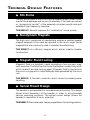
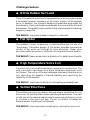
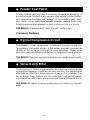
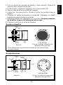
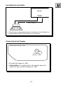
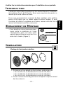
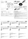
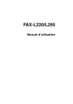
PUNCH
AUDIOPHILE
SYSTEM
RFA-414
RFA-514
RFA-614
INSTALLATION & OPERATION
®
®
Dear Customer,
Congratulations on your purchase of the world's finest brand of car audio speakers. At
Rockford Fosgate we are fanatics about musical reproduction at its best, and we are
pleased you chose our product. Through years of engineering expertise, hand craftsmanship and critical testing procedures, we have created a wide range of products that
reproduce music with all the clarity and richness you deserve.
For maximum performance we recommend you have your new Rockford Fosgate
product installed by an Authorized Rockford Fosgate Dealer, as we provide specialized
training through Rockford Technical Training Institute (RTTI). Please read your
warranty and retain your receipt and original carton for possible future use.
Great product and competent installations are only a piece of the puzzle when it comes
to your system. Make sure that your installer is using 100% authentic installation
accessories from Connecting Punch in your installation. Connecting Punch has
everything from RCA cables and speaker wire to Power line and battery connectors.
Insist on it! After all, your new system deserves nothing but the best.
To add the finishing touch to your new Rockford Fosgate image order your Rockford
wearables, which include everything from T-shirts and jackets to hats and sunglasses.
To get a free brochure on Rockford Fosgate products and Rockford accessories, in the
U.S. call 602-967-3565 or FAX 602-967-8132. For all other countries, call +001-602967-3565 or FAX +001-602-967-8132.
PRACTICE SAFE SOUND™
CONTINUOUS EXPOSURE TO SOUND PRESSURE LEVELS OVER
100dB
MAY CAUSE PERMANENT HEARING LOSS. HIGH
POWERED AUTOSOUND SYSTEMS MAY PRODUCE SOUND
PRESSURE LEVELS WELL OVER
130dB. USE COMMON SENSE
AND PRACTICE SAFE SOUND.
If, after reading your manual, you still have questions regarding this product,
we recommend that you see your Rockford Fosgate dealer. If you need further
assistance, you can call us direct at 1-800-795-2385. Be sure to have your serial
number, model number and date of purchase available when you call.
The serial number can be found on the outside of the box. Please record it in
the space provided below as your permanent record. This will serve as
verification of your factory warranty and may become useful in recovering your
product if it is ever stolen.
Serial Number: ________________________________
Model Number: ________________________________
TABLE
OF
CONTENTS
Introduction ...............................................................................................
Amplifier Accessory Pack ......................................................................... 1
Technical Design Features ....................................................................... 2
Design Features ........................................................................................ 5
Installation Considerations ....................................................................... 7
Mounting Location ................................................................................... 8
Battery and Charging ................................................................................ 9
Wiring the System .................................................................................... 9
Using the XCard ..................................................................................... 12
Resistor Chart ......................................................................................... 13
Installation ............................................................................................. 14
System Diagrams .................................................................................... 18
Rockford Fosgate Accessories ................................................................. 22
Troubleshooting ..................................................................................... 26
Dynamic Power Measurements .............................................................. 29
Specifications ......................................................................................... 31
Warranty Information ............................................................................. 33
International Information ........................................................................ 34
G E T T I N G S TA R T E D
Welcome to Rockford Fosgate! This manual is designed to provide
information for the owner, salesperson and installer. For those of you
who want quick information on how to install this product, please turn
to the Installation Section of this manual or refer to the icons listed
below. Other information can be located by using the Table of Contents.
We, at Rockford Fosgate, have worked very hard to make sure all the
information in this manual is current. But, as we are constantly finding
new ways to improve our product, this information is subject to change
without notice.
®
®
I
N
S
T
A
L
L
A
T
I
O
N
Sections marked
INSTALLATION
include “slam dunk”
wiring connections
TROUBLE-S
H
O
O
T
I
N
G
Sections marked
TROUBLESHOOTING
include recommendations
for curing
installation problems
INTRODUCTION
This manual provides information on the features and installation of
the Punch AUDIOphile Systems. We suggest you save this manual
for future reference.
We strongly recommend you have your Authorized Rockford Fosgate
Dealer install the Punch AUDIOphile System. If you do choose to
install the system yourself, please be sure to read the entire manual
before beginning.
P ACKAGE C ONTENTS
RFA-414
(1) Installation & Operation Manual
(2) 4" Midrange Speakers
(2) 4" Speaker Grilles
(2) Speaker Grille Rings
(2) Speaker Grille Gaskets
(8 Tinnerman Clips
(2) RFA-142x Crossovers
(2) 20mm Tweeters
(2) Surface Mount Cups
(2) Surface Mount Baseplates
(2) Flush Mount Cups
(2) Flush Mount Baseplates
(2) Mounting Brackets
(2) 6' 24 gauge speaker wire
(16) #8 x .75 Phillips Mounting Screws
(4) 8-32 x .50 Hex Head Bolts
(4) 8-32 Nuts
RFA-514
(1) Installation & Operation Manual
(2) 5.25" Midrange Speakers
(2) 5.25" Speaker Grilles
(2) Speaker Grille Rings
(2) Speaker Grille Gaskets
(8) Tinnerman Clips
(2) RFA-142x Crossovers
(2) 20mm Tweeters
(2) Surface Mount Cups
(2) Surface Mount Baseplates
(2) Flush Mount Cups
(2) Flush Mount Baseplates
(2) Mounting Brackets
(2) 6' 24 gauge speaker wire
(16) #8 x .75 Phillips Mounting Screws
(4) 8-32 x .50 Hex Head Bolts
(4) 8-32 Nuts
RFA-614
(1) Installation & Operation Manual
(2) 6.5" Midrange Speakers
(2) 6.5" Speaker Grilles
(2) Speaker Grille Rings
(2) Speaker Grille Gaskets
(8 Tinnerman Clips
(2) RFA-142x Crossovers
(2) 20mm Tweeters
(2) Surface Mount Cups
(2) Surface Mount Baseplates
(2) Flush Mount Cups
(2) Flush Mount Baseplates
(2) Mounting Brackets
(2) 6' 24 gauge speaker wire
(16) #8 x .75 Phillips Mounting Screws
(4) 8-32 x .50 Hex Head Bolts
(4) 8-32 Nuts
–1–
TECHNICAL D E S I G N F E AT U R E S
◆ Silk Dome
The silk dome used in the AUDIOphile tweeter allows linear movement of the diaphragm and voice coil assembly. The linear movement
or “symmetrical control” of the assembly provides smooth and well
extended high frequency response.
THE RESULT: Smooth response for “audiophile” sound quality.
◆ Neodymium Magnets
The high ionic compound of neodymium enables a smaller tweeter
magnet assembly to be used as opposed to the much larger ferrite
magnets that are commonly used in speaker manufacturing.
THE RESULT: An efficient magnet which allows smaller tweeter
construction.
◆ Magnetic Fluid Cooling
Magnetic fluid is a synthetic liquid consisting of microscopic magnetic particles. The fluid has four times the thermal conductivity as air
which makes it an ideal cooling agent. Magnetic fluid is injected into
the voice coil gap which helps dissipate heat generated by the voice
coil.
THE RESULT: A thermal conductor which allows increased power
handling.
◆ Swivel Mount Design
The tweeter is encapsulated in a variable swivel housing. This design
allows direct dispersion of the tweeter in order to accommodate
various mounting positions. The swivel mount design allows the
tweeter to maximize its sonic potential.
THE RESULT: Precise tweeter imaging regardless of mounting position.
–2–
Midrange Features
◆ Nitrile Rubber Surround
The nitrile material is resilient to temperature variations and provides
a consistent support necessary of the linear motion of the speaker
cone, In addition, the inherent damping capabilities eliminates the
transmission of sonic disturbances between the cone and the frame of
the speaker. This greatly improves the clarity of the speaker's midrange
frequency response.
THE RESULT: Improves speaker's frequency response.
◆ Flat Spider
The speaker's linear compliance is balanced through the use of a
“proprietary” flat spider design. A flat spider provides symmetrical
control of the voice coil through its cone excursion. Linear cone
excursion reduces harmonic distortion for improved sound quality.
THE RESULT: Reduces mechanical distortion for better sound quality
.
◆ High Temperature Voice Coil
The voice coil is of a high temperature copper wire construction. The
wire is wound in two layers on a black, anodized, aluminum voice
coil former. The voice coil former dissipates heat away from the voice
coil improving the speaker's thermal stability and improving the
reliability of the speaker.
THE RESULT: Improves reliability by dissipating generated heat.
◆ Vented Pole Piece
The vented pole piece by design, ensures proper ventilation to cool
the voice coil and maintain lower operating temperatures. The vent
on the rear of the magnet reduces back pressure and allows cool air
to circulate in the voice coil gap. The air circulation increases the
thermal power handling of the speaker.
THE RESULT: Improves power handling by cooling the voice coil.
–3–
◆ Powder Coat Finish
Powder coating has long been the industry standard for durability in
protective metal finishes. A dry powder (non-aerosol) is electrostatically applied to the metal and “baked” on to provide a hard “shelllike” finish. As an additional benefit, powder coating is the only
finishing process that releases no toxic chemicals into our ozone.
THE RESULT: A durable and “earth friendly” metal finish.
Crossover Features
◆ Optical Compression Circuit
The speaker's linear compliance is balanced through the use of a
“proprietary” flat spider design. A flat spider provides symmetrical
control of the voice coil through its cone excursion. Linear cone
excursion reduces harmonic distortion for improved sound quality.
THE RESULT: Reduces mechanical distortion for better sound quality
.
◆ Series Notch Filter
The Series Notch Filter compensates for the inductive load presented
by the driver (speaker). The filter's primary function is to dampen and
eliminate the effect that driver resonance has on the crossover. The
Series Notch Filter flattens out the inductive load which greatly
improves driver performance by providing a “stable” crossover point.
THE RESULT: Improves driver performance by reducing resonant
peak.
–4–
◆ Zobel Network
The Zobel network compensate for the impedance rise presented by
the driver (speaker). The network flattens out the gradual impedance
rise produced by the voice coil which typically results in high
frequency rolloff. The Zobel Network compensates for this natural
rolloff which allows the driver to produce a more linear response up
to the tweeter crossover point.
THE RESULT: Compensates for natural high frequency rolloff of
midrange.
◆ Adjustable Tweeter Level Matching
The RFA-142x utilizes a series power resistor for tweeter level
matching. The factory set tweeter output level is –0dB, however, can
be reduced –3dB to create a smoother transition between the midrange
and tweeter. The ability to level match allows the system to be custom
“tuned” for a particular listener or setup.
THE RESULT: Allows custom setup of tweeter output level.
–5–
D ESIGN F EATURES
1
7
6
®
®
2
3
®
®
ACTIVE TWEETER PROTECTION
RFA-142x
®
2
4
5
1. Wire Mesh Grille – The Wire Mesh Grille protects the tweeter
diaphragm from foreign objects and curious fingers.
2. Input Terminals – The “+” Terminal indicates the positive/plus
terminal of the speaker. The “–” Terminal indicates the negative/
minus terminal of the speaker. These terminals connect to the
corresponding output of the supplied crossover.
3. Variable Mount Logo – The Diamond “R” logo can be orientated
in its housing to accommodate vertical or horizontal crossover
mounting.
4. Input Screw Terminals – The Input Screw Terminals connect to
the outputs of the amplifier. These terminals accept bare wire or
1/4" spade lugs and are gold-plated to resist corrosion.
5. Output Screw Terminals – The Output Screw Terminals connect
to the input of the tweeter and midrange. These terminals accept
bare wire or 1/4" spade lugs and are gold-plated to resist corrosion.
6. Surface Mount Cup – This cup is used to “surface mount” the
tweeter on a panel.
7. Flush Mount Cup – This cup is used to recess or “flush mount” the
tweeter into a panel.
–6–
I NSTALLATION C ONSIDERATIONS
Tools Needed
The following is a list of some of the tools necessary for the installation
of your speakers.
Power Drill with assorted bits
Tape Measure
Voltmeter
#2 Phillips Screwdriver
Hole Saw (2")
General
1. For safety, disconnect the negative lead from the battery prior to
beginning the installation.
2. Never run wires underneath the vehicle. Running the wires inside
the vehicle provides the best protection.
3. Avoid running wires over or through sharp edges. Use rubber of
plastic grommets to protect any wires routed through metal.
4. Mount the speakers/crossovers away from electrical sources (other
than the amplifier) i.e.., power cables, electronic fuel pumps,
vehicle computers, and other potential noise sources.
5. Mount the speakers/crossovers away from areas of extreme heat or
moisture.
Speakers
1. Make sure there is an area large enough of the speaker to mount.
Warning! Failure to do this can cause damage to the speaker if the
speaker frame is bent during installation.
2. Check to see that the location is deep enough for the speaker(s) and
the location does not interfere with the normal operation of the
vehicle.
3. When mounting the speaker(s) in the door of a vehicle, make sure
the speaker(s) do not interfere with either the door or window
operation.
4. When mounting the speaker(s) on the rear deck of the vehicle, check
the operation of the rear hatch or trunk lid. Make sure the torsion bars
and other moving parts are not obstructed by the speaker(s) installation.
• Please refer to the Specifications section of this manual for proper
mounting diameter and depth of the speaker(s).
Crossovers
1. Make sure there is a flat area large enough for the crossover to mount.
2. For best results, mount the crossover(s) next to the amplifier for a
decorative finish to the installation and provide an easy upgrade (no
new wires to run) for a bi-amp Rockford Fosgate system in the future.
–7–
M OUNTING L OCATION
A solid front stage with a good image is one of the most difficult tasks
to achieve in a vehicle. No car has the optimum listening environment.
This makes proper sound staging very difficult to accomplish. Most
speakers tend to be placed where they will fit easily, as opposed to
where they can perform the best. The mounting location of your
speakers will have a great effect on the sound quality of your stereo
system. The special care taken to place the speakers will yield many
hours of listening enjoyment in return. Several important recommendations should be followed.
• Place the speakers where they have a
direct path to the listening area.
• For the best integration between the
midrange and tweeter, the tweeter should
2" or less
be placed less than 2" from the midrange.
(Figure 1)
• If you cannot place the tweeter less than
2" from the midrange, then place the
tweeter more than 7" from the midrange.
Figure 1
Placing the tweeter 2"-7" from the
midrange can cause destructive interference (frequency response problems) which will affect the speaker's
ability to reproduce the frequency range around the crossover
frequency of the system.
• Whenever possible, place the tweeter directly above or below the
midrange as this maximizes the imaging (point source) capability of
the espeakrs. (Figure 2)
Figure 2-A
Figure 2-B
–8–
• Sound radiated from a “point source” has the most optimum stereo
imaging because the separation of the acoustical centers between
the midrange and tweeter for each channel is at the optimum. Figure
2-A describes a horizontal speaker alignment. In a closed environment such as an automobile, horizontal speaker alignment can
cause severe amplitude and phase differences which will degrade
not only the imaging, but also the frequency response. This is due to
the path length differences between the midrange and tweeter.
Figure 2-B displays a vertical alignment between the midrange and
tweeter. With a vertical alignment, the path length difference
between the midrange and tweeter are reduced to a minimum. The
result is a negligible difference in path lengths between the midrange
and tweeter regardless of the proximity of the listener to the
speakers. Mounting the speaker with minimum path length difference will ensure the best staging an imaging possible from your
audio system.
INSTALLATION
Mounting the Midrange
®
®
I
N
S
T
A
L
L
A
T
I
O
N
1. Cut the proper size hole for the midrange/woofer.
• For the RFA-44, cut a 4" (101.6mm) diameter hole
• For the RFA-54, cut a 415⁄16"
• For the RFA-64, cut a 527⁄32"" (148.4mm) diameter hole
2. Place the mounting ring over the mounting hole and mark the
location of the screw mounting holes.
3. Remove the ring. Drill the holes for the screws using a 1/8" drill bit.
4. Route the wire through the hole.
5. Install the screw clips (Tinnerman clips) over the screw holes. Place
the mounting ring over the hole.
6. Attach the wires and be sure to observe the proper speaker polarity.
7. Place the speaker into the hole and screw the speaker into place.
Be careful not to bend the speaker frame during this step.
8. Press the speaker grille into the mounting ring.
–9–
Surface Mount Tweeter (Method #1)
®
Mounting
Baffle
Mounting
Screw
Surface
Mount
Baseplate
Surface
Mount
Cup
Front View
Exploded View
(twist clockwise to lock)
• Use when mounting tweeter to a solid surface (metal, wood, etc.)
Surface Mount Tweeter (Method #2)
Mounting
Baffle
Mounting
Bolt
Nut
Surface
Mount
Baseplate
Surface
Mount
Cup
Front View
Exploded View
(twist clockwise to lock)
• Use when mounting tweeter to a surface needing reinforcement
– 10 –
®
I
N
S
T
A
L
L
A
T
I
O
N
®
Flush Mount Tweeter
Mounting
Bolt
Mounting
Baffle
Nut
2" Cutout
Flush
Mount
Baseplate
Bracket
Flush
Mount
Cup
Rear View
(twist clockwise to lock)
Exploded View
Crossover Connections
HP CROSSOVER
LP CROSSOVER
TWEETER
PROTECTION
TWEETER
(Rear View)
®
“+”
–
+
Input
OUTPUT
FROM
AMPLIFIER
–
+
–
+
Mid
Output
–
+
Tweeter
Output
• Striped Wire indicates “+” terminal of tweeter
• Be Sure to Maintain Speaker Polarity
– 11 –
“+”Dot
®
I
N
S
T
A
L
L
A
T
I
O
N
®
Bandpassing the Midrange
RFA-142x
Midrange
Output
+
–
–
+
400µf capacitor
• To bandpass the midrange, it is necessary to add a 400µf
capacitor in series with the speaker
Tweeter Level Matching
Cut jumper
wire for –3dB
• Factory set tweeter level is –0dB
• Cut jumper wire on bottom of crossover to reduce
tweeter level by –3dB
– 12 –
®
I
N
S
T
A
L
L
A
T
I
O
N
®
Horizontal Logo Mounting
®
®
®
ACTIVE TWEETER PROTECTION
RFA-142x
®
ACTIVE TWEETER PROTECTION
RFA-142x
®
®
• Configure logo into desired position and snap into place
®
®
®
®
ACTIVE TWEETER PROTECTION
RFA-142x
®
®
ACTIVE TWEETER PROTECTION
RFA-142x
Vertical Logo Mounting
• Configure logo into desired position and snap into place
– 13 –
®
I
N
S
T
A
L
L
A
T
I
O
N
TROUBLESHOOTING
Symptom
No sound from
speakers
Diagnosis
Remedy
Wires between amplifier,
crossover and speakers
not connected properly.
Check and repair or replace
wiring as needed.
Amplifier has no output.
Check system with known
working amplifier and repair or replace as needed.
Speaker wires are shorted
to each other or to the
chassis of the vehicle.
Check for shorts in the wiring with a volt/ohm meter
and repair or replace wires
as needed
Speakers are blown.
Check system with known
working speaker and repair
or replace as needed.
Distorted sound
from speakers
Incorrect wiring between crossover and
speakers
Check wiring and repair or
replace as needed.
Tweeters “burn
up” easily
Excessive clipping from
amplifier
Check gain settings on amplifier and readjust as necessary
Equalizer in system (if
available) has excessive
boost in the high frequency range
Check settings on equalizer
and readjust as necessary
– 14 –
Symptom
Engi ne Noise
from One or
More Speakers
Diagnosis
Remedy
Speaker wires shorted to
chassis of vehicle.
Check for shorts in the wiring with a volt/ohm meter
and repair or replace wires
as needed.
Speaker wires are routed
near radiated noise
source. (Power cables,
vehicle computers, etc.)
Re-route speaker wiring
away from noise sources.
(Refer to the Installation
Considerations section of
this manual.)
Crossover is mounted
near radiated noise
source. (Power cables,
vehicle computers, etc.)
Move crossovers away from
noise sources. (Refer to the
Installation Considerations
section of this manual.)
– 15 –
TROUBLE-S
H
O
O
T
I
N
G
S P E C I F I C AT I O N S
Model
RFA-14
Freq. Response
RFA-44
3kHz-20kHz 3kHz-20kHz
RFA-54
RFA-64
44Hz-6kHz 39Hz-6kHz
Power Handling
(RMS)
50 Watts*
30 Watts
50 Watts
80 Watts
Nom. Impedance
4Ω
4Ω
4Ω
4Ω
92dB
86dB
86dB
89dB
Fs (Hz)
2000Hz
94Hz
44Hz
39Hz
Mounting Diameter
Refer to
drawing
4"
(101.6mm)
47⁄8"
(122.8mm)
55⁄8"
(142.9mm)
Mounting Depth
Refer to
drawing
1
(45.2mm)
25⁄8"
66.7mm)
33⁄32"
(78.6mm)
Sensitivity
1W/1M)
*Power ratings (PE) is established with recommended filter network.
Model
RFA-142x
Crossover Frequency
6kHz @ 4Ω
Crossover Slope
18dB/octave High-Pass
12dB/octave Low-Pass
Protection Circuitry
Optical Compression
Crossover Alignment
Butterworth
Zobel Network
Effective @ 6.5kHz
Series Notch Filter
Effective @ 2kHz
Tweeter Level Matching
Factory set –0dB
User selectable –3dB
Surface Mount
Flush Mount
7⁄16" (11.1mm)
11⁄16"
(27mm)
3⁄4" (19mm)
21⁄8" (50.8mm)
2" (54mm)
25⁄16"
®
®
13⁄32"
(28.3mm)
(58.4cm)
ACTIVE TWEETER PROTECTION
RFA-142x
®
(End View)
(Specifications are subject to change without notice)
– 16 –
L IMITED W A R R A N T Y I N F O R M AT I O N
Rockford Corporation offers a limited warranty on Rockford Fosgate products on the
following terms:
• Length of Warranty
1 year on speakers
3 years on electronics
2 years on source units
30 days on speaker B-stock (receipt required)
90 days on electronic B-stock (receipt required)
• What is Covered
This warranty applies only to Rockford Fosgate products sold to consumers by
Authorized Rockford Fosgate Dealers in the United States of America or its
possessions. Product purchased by consumers from an Authorized Rockford
Fosgate Dealer in another country are covered only by that country’s Distributor
and not by Rockford Corporation.
• Who is Covered
This warranty covers only the original purchaser of Rockford product purchased
from an Authorized Rockford Fosgate Dealer in the United States. In order to
receive service, the purchaser must provide Rockford with a copy of the receipt
stating the customer name, dealer name, product purchased and date of purchase.
• Products found to be defective during the warranty period will be repaired or
replaced (with a product deemed to be equivalent) at Rockford's discretion.
• What is Not Covered
1. Damage caused by accident, abuse, improper operations, water, theft
2. Any cost or expense related to the removal or reinstallation of product
3. Service performed by anyone other than Rockford or an Authorized Rockford
Fosgate Service Center
4. Any product which has had the serial number defaced, altered, or removed
5. Subsequent damage to other components
6. Any product purchased outside the U.S.
7. Any product not purchased from an Authorized Rockford Fosgate Dealer
• Limit on Implied Warranties
Any implied warranties including warranties of fitness for use and merchantability
are limited in duration to the period of the express warranty set forth above. Some
states do not allow limitations on the length of an implied warranty, so this
limitation may not apply. No person is authorized to assume for Rockford Fosgate
any other liability in connection with the sale of the product.
• How to Obtain Service
Please call 1-800-669-9899 for Rockford Customer Service. You must obtain an
RA# (Return Authorization number) to return any product to Rockford Fosgate. You
are responsible for shipment of product to Rockford.
Ship to: Electronics
Rockford Corporation
Warranty Repair Department
2055 E. 5th Street
Tempe, AZ 85281
RA#:_________________
Ship to: Speakers
Rockford Acoustic Design
(Receiving-speakers)
609 Myrtle N.W.
Grand Rapids, MI 49504
RA#:_________________
– 17 –
A
A
TI
N
T
M
O
ER
IO
R
N
T
N
FO
IN
A
L
IN
– 18 –
LEA DETENIDAMENTE LAS SIGUIENTES INSTRUCCIONES DE
INSTALACIÓN DEL PRODUCTO.
I NTRODUCCIÓN
Este manual contiene información sobre la construcción, installación y
funcionamiento de los sistemas Punch AUDIOphile. Le recomendamos
que conserve el manual para futuras consultas.
Es preferible que la instalación de sistema Punch AUDIOphile sea
realizada por un distribuidor autorizado Rockford Fosgate. Si prefiere
realizar la instalación usted mismo, asegurese de leer el manual en su
totalidad antes de comenzar.
M ONTAJE
• Le mejor interacción entre tweeter y
medio se consigue si no están separados
entre si más de 5 cenimetros. (Figura 1)
no superior a 5cm
Figura 1
I NSTALACIÓN
®
Montaje del altavoz de medios
1. Corte el agujero para el medio/woofer.
• Par el RFA-44, corte un circulo de 101.6mm de diámetro
• Par el RFA-54, corte un circulo de 125.4mm de diámetro
• Par el RFA-64, corte un circulo de 148.4mm de diámetro
– 19 –
®
I
N
S
T
A
L
L
A
T
I
O
N
Mounting
Baffle
Mounting
Bolt
Nut
Surface
Mount
Baseplate
Surface
Mount
Cup
Seccion
Vista Frontal
(Gire en el sentido contrario a las
agujas del reloj para fijar)
• Use la base extra cuando monte el tweeter en una superficie que
necesite refuerzo.
Montaje Empotrado
Mounting
Bolt
Mounting
Baffle
Nut
2" Cutout
Bracket
Flush
Mount
Baseplate
Flush
Mount
Cup
Vista de Atrás
Seccion
(Gire en el sentido contrario a las
agujas del reloj para fijar)
– 20 –
E SPAÑOL
2. Use los anillos de montaje de plástico como plantilla. Marque la
posición de los tornills de anclaje.
3. Quite el anillo y perfore los agujeros con una broca de 1/8".
4. Pase el cable de altavoz a través del agujero.
5. Instale los clips para tornillo. Monte el anillo de montaje sobre el
agujero.
6. Conecte los cables observando la polaridad. Mantenga los cables
alejados pe partes móviles o cortantes.
7. Asegure el altavoz en la abertura con los tornillos. Tenga la precaución
de no doblar el marco del altavoz en este proceso.
8. Presione la rejilla en el anillo de montaje.
Montaje en Superficie
®
Paso Banda Para del Medio
RFA-142x
Midrange
Output
+
–
–
+
400µf capacitor
• Para hacer un paso banda para el medio se ha de añadir un
condensador de 400µf en serie con el altavoz
Ajuste de Nivel del Tweeter
(Vista inferior del RFA-142x)
Cut jumper
wire for –3dB
• El ajuste de origen es –0dB
• Corte el hilo en la parte inferior del tweeter para una
reduccion del nivel del tweeter de –3dB
– 21 –
®
I
N
S
T
A
L
L
A
T
I
O
N
Veuillez lire les instrucitons suivantes pour l'installation de ces produits.
I NTRODUCTION
Ce manuel contient des informations sur les caractéristiques et l'installation
des systèmes Punch AUDIOphile. Nous vous proposons de garder ce
manuel pour toute référence future.
EMPLACEMENT DE MONTAGE
• Pour bénéficier d'une harmonie maximum entre le médium et l'aigu
l'éloignement entre ces deux hautparleurs devrait être de moins de 5 cm
entre les 2 chassis. (Figure 1)
moins de 5cm
Figure 1
INSTALLATION
®
Montage du haut-parleur médium
®
I
N
S
T
A
L
L
A
T
I
O
N
1. Découper un trou adapté au haut-parleur médium/woofer.
• Pour le RFA-44, le diamètre du trou est de 101,6mm
• Pour le RFA-54, le diamètre du trou est de 125,4mm
• Pour le RFA-64, le diamètre du trou est de 148,4mm
2. Placer l'anneau de montage sur le trou et repérer l'emplamcement
des trous des vis.
– 22 –
FRANCAIS
Nous vous recommandons vivement de faire installaer votre système
punch AUDIOphile par un dealer agréé Rockford Fosgate. Si vous
choisissez d'installer le système vous même, assurez-vous de lire ce
manuel entièrement avant de commencer.
3. Retirer l'anneau. Percer les trous des vis en utilisant une mèche de 3mm.
4. Faire passer les fils dans le trou central.
5. Installer les clips (clips Tinnerman) sur les trous des vis. Placer l'anneau
de montage au-dessus du trou central.
6. Connecter les fils au haut-parleur en respectant les polarités. Eloigner les
fils de toute partie tranchante ou mobile du véhicule.
7. Placer le haut-parleur au-dussus du trou central. Visser le haut-parleur
dans son emplacement. Faire attention à ne pas tordre le chassis du
haut-parleur durant cette étape de montage.
8. Mettre la grille dans l'anneau de montage.
Montage en surface du tweeter
écrou
Nut
Surface de
Mounting
Montage
Baffle
Mounting
Vis
Bolt
Bague
de
Surface
Mount
Montage
Baseplate
en Surface
Support
Surfacede
Montage
Mount
en Cup
Surface
Vue de Face
(Tourner dans le sens horlogique
pour verrouiller)
Vue Explosée
• Ajouter une bague de montage supplémentaire lorsque la surface de
montage doit être renforcée
Montage en affleurement du tweeter
Mounting
Vis
Bolt
Surface de
Mounting
Montage
Baffle
écrou
Nut
Découpe
2"deCutout
5cm
Bracket
Plaque
de
Fixation
Flush
Bague
de
Mount
Montage
en
Baseplate
Affleurement
Flush de
Support
Mount en
Montage
Cup
Affleurement
Vue Arrière
(Tourner dans le sens horlogique
pour verrouiller)
Vue Explosée
– 23 –
Bandpassing the Midrange
RFA-142x
Midrange
Output
+
–
–
400µf capacitor
+
• To bandpass the midrange, it is necessary to adda 400µf
capacitor in series with the speaker
Compensation du Niveau Aigu
Vue d'en bas du PCH-142x
jumper
Coupez Cut
le pontage
au
for –3dB
verso duwire
filtre pour
–3dB
• Le niveau de défaut est de –0dB
• Coupez le pontage au verso du filtre our atténuer l'aigu de 3dB.
– 24 –
Die folgende Bedienungsanleitung soll Ihnen beim Einbau eine Hilfestellung
geben.
E NLEITUNG
Diese Bedienungsanleitung enthält Informationen für den Gebrauch und
Einbau des Punch AUDIOphile Systems. Wire empfehlen, sie auch für
Fragen in der Zukunft sorgfältig aufzubewahren.
Es ist empfehlenswert, sich das Punch AUDIOphile System von einem
Autorisierten Rockford Fosgate Fachhändler einbauen zu lassen. Sollten
Sie den Einbau jedoch selber vornehmen wollen, so empfehlen wir Ihnen
diese Bedienungsanleitung sorgfälitg zu lesen.
EINBAUORT
• Für das optimale Zusammenspiel von
Mittel- und Hochtöner, sollte der
Hochtöner niemals weiter als 5cm vorn
Mitteltöner entfernt montiert werden.
(Abb. 1)
Abstand max. 5cm
(Abb. 1)
EINBAU
®
I
N
S
T
A
L
L
A
T
I
O
N
1. Schneiden Sie die richtige Lochgröβe für den Mitteltöner oder
Midbaβ aus.
• Für den RFA-44, schneiden Sie ein 101,6cm Ø Loch
• Für den RFA-54, schneiden Sie ein 125,4cm Ø Loch
• Für den RFA-64, schneiden Sie ein 148,4cm Ø Loch
2. Setzen Sie den Montagering auf das Loch und markieren Sie die
Löcher für die Schrauben.
– 25 –
DEUTSCH
Montage des Mitteltöners
®
3. Nehmen Sie den Ring wieder ab und bohren Sie dann, mit einem
passenden Bohrer, die Schraubenlöcher vor.
4. Führen Sie das Kabel durch das Loch.
5. Stecken Sie die Schraubenships über die Schraubenlöcher. Plazieren
sie den Montagering über dem Loch.
6. Schlieβen Sie die Lautsprecherkabel an. Kontrollieren Sie, ob die
Polarität stimmt. Stellen Sie sicher, daβ das Lautsprecherkabel an
keinen scharfen oder sich bewegenden Teilen anliegt.
7. Plazieren Sie den Lautsprecher im Loch und befestigen ihn. Seien
Sie dabei vorsichtig daβ sich der Lautsprecherkorb nicht verzieht.
8. Drücken Sie das Lautsprechergitter im Montagering fest.
Hochtöner Aufbau-Montage
écrou
Nut
Surface de
Mounting
Montage
Baffle
Mounting
Vis
Bolt
Bague
de
Surface
Mount
Montage
Baseplate
en Surface
Support
Surfacede
Montage
Mount
en Cup
Surface
Front-Ansicht
(Im Uhreigersinn drehen)
Spreng Zeichnung
• Use when mounting tweeter to a solid surface (metal, wood, etc.)
Hochtöner Einbau-Montage
Mounting
Vis
Bolt
Surface de
Mounting
Montage
Baffle
écrou
Nut
Découpe
2"deCutout
5cm
Bracket
Plaque
de
Fixation
Flush
Bague
de
Mount
Montage
en
Baseplate
Affleurement
Flush de
Support
Mount en
Montage
Cup
Affleurement
Vue Arrière
(Tourner dans le sens horlogique
pour verrouiller)
Spreng Zeichnung
– 26 –
Bandpassing the Midrange
RFA-142x
Midrange
Output
+
–
–
400µf capacitor
+
• To bandpass the midrange, it is necessary to adda 400µf
capacitor in series with the speaker
Tweeter Level Matching
Bottom view of RFA-142x
Cut
jumper
Cut jumper
wire
for –3dB
wire for –3dB
• Factory set tweeter level is –0dB
• Cut jumper wire on bottom of crossover to reduce tweeter level
by –3dB
– 27 –
Leggere le istruzioni seguenti prima dell'installazione del prodotto.
I NTRODUZIONE
Questo manuale fornisce informazioni sulle caratteristiche e sul
installazione dei sistemi Punch AUDIOphile. Vi suggeriamo di conservare
questo manuale come riferimento futuro.
Raccomandiamo fortemente che is sistema sia installato dal vostro
rivenditore Rockford Fosgate. Se scegliete di procedere con l'installazione
da soli, leggete attentamente tutto il manuale prima di proseguire.
P OSIZIONAMENTO
• Per ottenere la miglior integrazione tra
tweeter e midrange, vi suggeriamo di
posizionare i due componenti a meno
di 5 cm tra loro. (Figura 1)
meno di 5 cm
Figura 1
INSTALLAZIONE
®
Installazione del Midrange
®
I
N
S
T
A
L
L
A
T
I
O
N
– 28 –
ITALIANO
1. Practicate un foro del diametro corretto per il midrange/woofer
• 101,6mm per RFA-44
• 125,4mm per RFA-54
• 148,4mm per RFA-64
2. Posizionate l'anello della griglia sul foro e segnate la posizione
delle viti.
3. Togliete l'anello e forate il pannello con una puna da 3,5mm.
4. Passate i cavi attraverso il foro.
5. Posizionate le clips di fissaggio sopra i fori delle viti e l'anello della
griglia sopra il foro dell'altoplarlante.
6. Collegate i cave assicurandovi di osservare la corretta polarità.
Assicuratevi di mantenere i cavi lontano da parti in movimento o
strutture taglienti.
7. Posizionate l'altoparlante nel foro ed avvitatelo. Assicuratevi di non
piegare il cestello dell'altoparlante.
8. Incastrate la griglia sull'anello di fissaggio.
Surface Mount Tweeter
Nut
Nut
Mounting
Mounting
Baffle
Baffle
Mounting
Mounting
BoltBolt
Surface
Surface
Mount
Mount
Baseplate
Baseplate
Surface
Surface
Mount
Mount
Cup
Cup
Front View
(twist clockwise to lock)
Exploded View
• Use when mounting tweeter to a surface needing reinforcement
Flush Mount Tweeter
Mounting
Mounting
Bolt
Bolt
Mounting
Mounting
Baffle
Baffle
Nut
Nut
2" Cutout
2" Cutout
Bracket
Bracket
Flush
Flush
Mount
Mount
Baseplate
Baseplate
Flush
Flush
Mount
Mount
Cup
Cup
Front View
(twist clockwise to lock)
Exploded View
– 29 –
Bandpassing the Midrange
RFA-142x
Midrange
Output
+
–
–
400µf capacitor
+
• To bandpass the midrange, it is necessary to adda 400µf
capacitor in series with the speaker
Tweeter Level Matching
Bottom view of RFA-142x
Cut
jumper
Cut jumper
wire
for –3dB
wire for –3dB
• Factory set tweeter level is –0dB.
• Cut jumper wire on bottom of crossover to reduce tweeter level
by –3dB.
– 30 –
MADE IN THE USA
This product is designed, developed and assembled in the USA by a dedicated
group of American workers. The majority of the components used in the
construction of this product are produced by American companies. However, due
to the global nature of their manufacturing facilities and the loudspeaker parts
industry in general, some parts may be manufactured in other countries.
Rockford Fosgate
Rockford Corporation
546 South Rockford Drive
Tempe, Arizona 85281 U.S.A.
In U.S.A., (602) 967-3565
In Europe, Fax (49) 4207-801250
In Japan, Fax (81) 559-79-1265
11/96
LIT9780