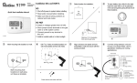
1
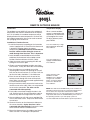
9025i
REMOTE OUTDOOR SENSOR
Introduction
The outdoor sensor (9025i) will sense the outdoor air
temperature and send this information to the thermostat. On all models, the outdoor temperature will be
displayed below the room temperature. On the 9720i,
the outdoor temperature also can be used to control
the upstaging of the thermostat.
Installation of Outdoor Sensor
11. Install the thermostat according to the instruction
manual supplied with it. Check that the thermostat
is operating. (Display shows the correct
temperature.) CAUTION: Remove the thermostat
from the subbase while wiring the sensor to
avoid damage from live wires. This is important.
12. Install shielded or nonshielded two wire twisted
cable from the thermostat to the outdoor sensor
location. Maximum distance is 300 ft. (100m).
13. Open the sensor case by grasping the side and
pulling the two halves apart.
14. Choose a protected outdoor location away from
heat sources, usually the north side of the building.
15. Use the subbase as a template to mark the
mounting holes and the wire opening on the wall.
Drill size for the wall anchors is 3/16 inch. Drill size
for the wire leads should be 1/2 inch diameter.
16. From the rear of the base push the end of the
remote sensor through the center of the plastic
plate. Make sure the sensor extends approximately
1/4 inch into the housing.
17. Using twisted wire cable, connect the leads of the
remote sensor to the cable. Wire nuts are provided
to secure the connection. The wires can be
connected with either polarity.
18. Push cable sensor leads through the hole in the
wall. Seal the hole in the wall around the cable to
eliminate any draft that might affect the sensor.
19. Secure subbase to wall with screws provided. Do
not use hex head screws. Snap cover onto remote
sensor base.
10. Connect the wires on the thermostat subbase to
the sensor terminals. Again, the wires can be
connected with either polarity. Connect the wires
to the terminal labeled “Outdoor Sensor”.
11. Mount the thermostat on the subbase and check
to be sure that it is showing the temperature.
Temperature Display
When a remote outdoor
sensor is connected to the
thermostat, the thermostat
will recognize the sensor.
To adjust balance points
press MENU.
Press the DOWN key to highlight INSTALLER SETTINGS.
Press SELECT.
MONDAY
11:30 AM
70.5˚
F
OUTSIDE 24˚F
HOLD TEMP
MENU
MENU
SELECT
INSTALLER SETTINGS
SYSTEM SETUP
RESIDUAL COOL
LOW BALANCE
HIGH BALANCE
HOME
Select either the LOW
BALANCE or HIGH
BALANCE. Press SELECT.
Using the UP or DOWN
button, change the balance
point to the desired level.
Press SELECT.
BACK
DAY / TIME
FAN
USER SETTINGS
INSTALLER SETTINGS
HOME
Press the DOWN key to
highlight LOW BALANCE.
Press SELECT.
HEAT
FAN AUTO
GAS
60
45˚F
95˚F
SELECT
BALANCE POINTS
LOW BALANCE
HIGH BALANCE
45˚F
95˚F
INSTALL MENU
SELECT
NOTE: The HIGH and LOW BALANCE points will affect the
upstaging of the thermostat. The 2nd stage heating will not
turn on unless the temperature falls below the HIGH
BALANCE point. The 1st stage heating will not activate if the
temperature falls below the LOW BALANCE point. Refer to
the operating manual of your heat pump system for
recommended HIGH and LOW balance point temperatures.
111-292C
9025i Remote Outdoor Sensor Installation Instructions
1
Connect wiring between
the thermostat and the
outdoor sensor (9025i).
Use twisted pair wiring
(22AWG minimum) with
a maximum length of
300 feet (or 100m).
2
Replace cover on thermostat.
Turn on power to unit and
proceed with programming
per instructions on the display
or in the user’s manual.
Climate Controls Americas
515 South Promenade Avenue
Corona, CA 92879-1736
United States of America
Made in Mexico
www.aboutinsight .com
©2003 Invensys
111-292C