1
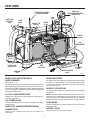
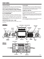
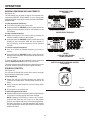
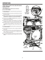
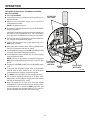
OPERATOR’S MANUAL JOB-SITE RADIO/RACE SCANNER R8408 BATTERIES AND CHARGERS SOLD SEPARATELY Your job-site radio/race scanner has been engineered and manufactured to our high standards for dependability, ease of operation, and operator safety. When properly cared for, it will give you years of rugged, trouble-free performance. WARNING: To reduce the risk of injury, the user must read and understand the operator’s manual before using this product. Thank you for buying a RIDGID® product. SAVE THIS MANUAL FOR FUTURE REFERENCE TABLE OF CONTENTS Introduction......................................................................................................................................................................2 General Safety Rules........................................................................................................................................................3 Specific Safety Rules........................................................................................................................................................4 Symbols............................................................................................................................................................................5 Electrical...........................................................................................................................................................................6 Features........................................................................................................................................................................ 7-9 Assembly........................................................................................................................................................................10 Operation.................................................................................................................................................................. 10-21 Maintenance...................................................................................................................................................................22 Warranty.........................................................................................................................................................................25 Customer Service Information.......................................................................................................................... Back Page INTRODUCTION This product has many features for making its use more pleasant and enjoyable. Safety, performance, and dependability have been given top priority in the design of this product making it easy to maintain and operate. GENERAL SAFETY RULES IMPORTANT SAFETY INSTRUCTIONS Protect the power cord from being walked on or pinched particularly at plugs, convenience receptacles, and the point where they exit from the apparatus. Unplug this apparatus during lightning storms or when unused for long periods of time. WARNING! Read THESE instructions. Failure to follow all instructions listed below, may result in electric shock, fire and/or serious personal injury. PERSONAL KEEP These Instructions HEED ALL WARNINGS FOLLOW ALL INSTRUCTIONS Work Area Avoid accidental starting. Be sure switch is in the locked or off position before inserting battery pack. Carrying products with your finger on the switch or inserting the battery pack into a product with the switch on invites accidents. Keep your work area clean and well lit. Cluttered benches and dark areas invite accidents. Do not operate products in explosive atmospheres, such as in the presence of flammable liquids, gases, or dust. Products create sparks which may ignite the dust or fumes. Do not overreach. Keep proper footing and balance at all times. Proper footing and balance enable better control of the product in unexpected situations. Do not use on a ladder or unstable support. Stable footing on a solid surface enables better control of the product in unexpected situations. ELECTRICAL SAFETY Product USE AND CARE A battery operated product with integral batteries or a separate battery pack must be recharged only with the specified charger for the battery. A charger that may be suitable for one type of battery may create a risk of fire when used with another battery. Use battery operated product only with specifically designated battery pack. Use of any other batteries may create a risk of fire. Use battery only with charger listed. MODEL BATTERY PACK CHARGER (12 V) 130252002 130254001 140276003 (14.4 V) 130254008 130254002 R8408 (18 V) 130254007 Do not use product if switch does not turn it on or off. A product that cannot be controlled with the switch is dangerous and must be repaired. Disconnect battery pack from product or place the switch in the locked or off position before making any adjustments, changing accessories, or storing the product. Such preventive safety measures reduce the risk of starting the product accidentally. When battery pack is not in use, keep it away from other metal objects like: paper clips, coins, keys, nails, screws, or other small metal objects that can make a connection from one terminal to another. Shorting the battery terminals together may cause sparks, burns, or a fire. 140276004 140276006 (R840091) (18 V) 130383002 (R84008) 140276006 (R840091) (24 V) 130377001 (R85008) (24 V) 140315001 (R85009) SAFETY Keep the radio and its handle dry, clean and free from oil and grease. Always use a clean cloth when cleaning. Never use brake fluids, gasoline, petroleum-based products, or any strong solvents to clean the radio. Following this rule will reduce the risk of loss of control and deterioration of the enclosure plastic. Do not use this apparatus near water. Clean only with dry cloth. Do not defeat the safety purpose of the polarized or grounding-type plug. A polarized plug has two blades with one wider than the other. A grounding type plug has two blades and a third grounding prong. The wide blade or the third prong are provided for your safety. If the provided plug does not fit into your outlet, consult an electrician for replacement of the obsolete outlet. Do not block any ventilation openings. Install in accordance with the manufacturer’s instructions. Do not install near any heat sources such as radiators, heat registers, stoves, or other apparatus (including amplifiers) that produce heat. Only use attachments/accessories specified by the manufacturer. SPECIFIC SAFETY RULES SERVICE Refer all servicing to qualified service personnel. Servicing is required when the apparatus has been damaged in any way, such as power-supply cord or plug is damaged, liquid has been spilled or objects have fallen into the apparatus, the apparatus has been exposed to rain or moisture, does not operate normally, or has been dropped. Product service must be performed only by qualified repair personnel. Service or maintenance performed by unqualified personnel may result in a risk of injury. When servicing a product, use only identical replacement parts. Follow instructions in the Maintenance section of this manual. Use of unauthorized parts or failure to follow Maintenance instructions may create a risk of shock or injury. IMPORTANT SAFETY INSTRUCTIONS Know your product. Read operator’s manual carefully. Learn its applications and limitations, as well as the specific potential hazards related to this product. Following this rule will reduce the risk of electric shock, fire, or serious injury. For best results, your battery product should be charged in a location where the temperature is more than 50°F but less than 100°F. To reduce the risk of serious personal injury, do not store outside or in vehicles. Battery products do not have to be plugged into an electrical outlet; therefore, they are always in operating condition. Be aware of possible hazards when not using your battery product or when changing accessories. Following this rule will reduce the risk of electric shock, fire, or serious personal injury. Under extreme usage or temperature conditions, battery leakage may occur. If liquid comes in contact with your skin, wash immediately with soap and water, then neutralize with lemon juice or vinegar. If liquid gets into your eyes, flush them with clean water for at least 10 minutes, then seek immediate medical attention. Following this rule will reduce the risk of serious personal injury. Do not place battery products or their batteries near fire or heat. This will reduce the risk of explosion and possibly injury. nTo reduce the risk of personal injury and electric shock, the product should not be played with or placed where small children can reach it. Do not crush, drop or damage battery pack. Do not use a battery pack or charger that has been dropped or received a sharp blow. A damaged battery is subject to explosion. Properly dispose of a dropped or damaged battery immediately. Batteries can explode in the presence of a source of ignition, such as a pilot light. To reduce the risk of serious personal injury, never use any cordless product in the presence of open flame. An exploded battery can propel debris and chemicals. If exposed, flush with water immediately. nTo reduce the risk of electric shock, do not expose to water or rain. If the power supply cord is damaged, it must be replaced only by the manufacturer or by an authorized service center to avoid risk. Save these instructions. Refer to them frequently and use them to instruct others who may use this product. If you loan someone this product, loan them these instructions also. Do not charge battery product in a damp or wet location. Following this rule will reduce the risk of electric shock. SYMBOLS Some of the following symbols may be used on this product. Please study them and learn their meaning. Proper interpretation of these symbols will allow you to operate the product better and safer. SYMBOL NAME DESIGNATION/EXPLANATION Wet Conditions Alert Do not expose to rain or use in damp locations. Read The Operator’s Manual To reduce the risk of injury, user must read and understand operator’s manual before using this product. Eye Protection Always wear safety goggles or safety glasses with side shields, or a full face shield when operating this product. Safety Alert Precautions that involve your safety. Electric Shock Alert Indicates uninsulated material within the unit that may cause electrical shock. Do not remove product covering. The following signal words and meanings are intended to explain the levels of risk associated with this product. SYMBOL SIGNAL MEANING DANGER: Indicates an imminently hazardous situation, which, if not avoided, will result in death or serious injury. WARNING: Indicates a potentially hazardous situation, which, if not avoided, could result in death or serious injury. CAUTION: Indicates a potentially hazardous situation, which, if not avoided, may result in minor or moderate injury. CAUTION: (Without Safety Alert Symbol) Indicates a situation that may result in property damage. SERVICE WARNING: Servicing requires extreme care and knowledge and should be performed only by a qualified service technician. For service we suggest you return the product to your nearest AUTHORIZED SERVICE CENTER for repair. When servicing, use only identical replacement parts. To avoid serious personal injury, do not attempt to use this product until you read thoroughly and understand completely the operator’s manual. If you do not understand the warnings and instructions in the operator’s manual, do not use this product. Call RIDGID® customer service for assistance. SAVE THESE INSTRUCTIONS ELECTRICAL DOUBLE INSULATION EXTENSION CORDS Double insulation is a concept in safety in electric products, which eliminates the need for the usual three-wire grounded power cord. All exposed metal parts are isolated from the internal metal motor components with protecting insulation. Double insulated products do not need to be grounded. When using a product at a considerable distance from a power source, be sure to use an extension cord that has the capacity to handle the current the product will draw. An undersized cord will cause a drop in line voltage, resulting in overheating and loss of power. Use the chart to determine the minimum wire size required in an extension cord. Only round jacketed cords listed by Underwriter’s Laboratories (UL) should be used. WARNING: The double insulated system is intended to protect the user from shock resulting from a break in the product’s internal wiring. Observe all normal safety precautions to avoid electrical shock. When using this product outdoors, use an extension cord that is designed for outside use. This type of cord is designated with “WA” on the cord’s jacket. Before using any extension cord, inspect it for loose or exposed wires and cut or worn insulation. NOTE: Servicing of a product with double insulation requires extreme care and knowledge of the system and should be performed only by a qualified service technician. For service, we suggest you return the product to your nearest authorized service center for repair. Always use original factory replacement parts when servicing. **Ampere rating (on product data plate) 0-2.02.1-3.4 3.5-5.0 5.1-7.0 7.1-12.0 12.1-16.0 Cord LengthWire Size (A.W.G.) 25'161616161414 ELECTRICAL CONNECTION 50'161616141412 This product should be connected to a power supply that is 120 volts, AC only (normal household current), 60 Hz. Do not operate this product on direct current (DC) through the power cord. A substantial voltage drop will cause a loss of power and the motor will overheat. If the product does not operate when plugged into an outlet, double-check the power supply. 100'1616141210 — **Used on 12 gauge - 20 amp circuit. NOTE: AWG = American Wire Gauge WARNING: Keep the extension cord clear of the working area. Position the cord so that it will not get caught on lumber, tools, or other obstructions while you are working with this product. Failure to do so can result in serious personal injury. WARNING: Check extension cords before each use. If damaged replace immediately. Never use a product with a damaged cord since touching the damaged area could cause electrical shock resulting in serious injury. FEATURES PRODUCT SPECIFICATIONS Operating Temperature Normal.......................................................... 32˚F - 104˚F Power Requirements 120 VAC through cord or 12 V DC, 14.4 V DC, 18 V DC, and 24 V DC RIDGID slide-mount batteries 3 AA (1.5 V DC) batteries for memory/clock backup Power Outputs 1 Automotive-type power receptacle, 12 V DC, 1 Amp Max. External Jacks Antenna Connector................... For single-wire antenna Headphone Jack................................................. 3.5 mm iPod Connector............. 30-pin iPod docking connector Input Jack....................................... 3.5 mm (Inside door) Size................................... 22 in. (L) x 13 in. (H) x 12 in. (W) Frequency Ranges AM Band................................................. 520-1710 (KHz) FM Band............................................ 87.5 - 108.1 (MHz) Race Band................. (UHF) 450.0375 - 469.9625 (MHz) Scan Rate (Race Band)................. 16 Channels per second Scan Delay............................................... 60 Microseconds Audio Output 13 Watts nominal into 4 Ω (Ohm) internal speakers 12.5 mW nominal into 32 Ω (Ohm) Headphone 25 mW nominal into 64 Ω (Ohm) Earphone Weight...................................................................... 23.5 lb. FCC COMPLIANCE Warning: Changes or modifications to this unit not expressly approved by the party responsible for compliance could void the user’s authority to operate the equipment. NOTE: This equipment has been tested and found to comply with the limits for a Class B digital device, pursuant to Part 15 of the FCC Rules. These limits are designed to provide reasonable protection against harmful interference in a residential installation. This equipment generates, uses and can radiate radio frequency energy and, if not installed and used in accordance with the instructions, may cause harmful interference to radio communications. However, there is no guarantee that interference will not occur in a particular installation. If this equipment does cause harmful interference to radio or television reception, which can be determined by turning the equipment on and off, the user is encouraged to try to correct the interference by one or more of the following measures: Reorient or relocate the receiving antenna. Increase the separation between the equipment and receiver. Connect the equipment into an outlet on a circuit different from that to which the receiver is connected. Consult the dealer or an experienced radio/TV technician for help. FEATURES AUDIO OUT (HEADPHONE/EARPHONE) CONNECTION FOLD-DOWN ROTATABLE FLEXIBLE ANTENNA TOP TRAY protective steel roll cage CORD WRAP BACKLIT LCD DISPLAY DIGITAL CLOCK DIGITAL KEYPAD iPod COMPARTMENT 12 V DC 1-AMP RECEPTACLE AUX 2 INPUT JACK A/C POWER CORD 30 PIN iPod DOCK (AUX 1) NON-SKID FEET KNOW YOUR job-site radio/ RACE SCANNER Fig. 1 bass boost/SKIP The bass boost can enhance the bass by three levels when the radio is in stereo mode. To use the SKIP feature when in race mode, you can program into memory the channels you wish to skip over. See Figures 1 - 2. The safe use of this product requires an understanding of the information on the product and in this operator’s manual as well as a knowledge of the project you are attempting. Before use of this product, familiarize yourself with all operating features and safety rules. BACKLIT LCD DISPLAY The backlit LCD display is clear and visible in all lighting conditions. NOTE: The illustrations of the LCD display shown in this manual are only examples of the frequencies you may see and program on your radio/scanner and are not the exact frequencies that you may choose to listen to and program. 12 v dc 1-amp receptacle Charge your cell phone or other electronics that require a 12 V DC connection. a/c power cord cord wrap Your job-site radio/race scanner can be plugged into an A/C power source. Use the convenient cord wrap located on top of the radio during transport. audio out (HEADPHONE/EARPHONE) connection DIGITAL CLOCK Displays the time in hours and minutes. Connect your headphones through the audio out connection. FEATURES Digital KeyPad race mode Use the digital keypad for direct input of a desired frequency. With digital tuning, you can preset up to ten of your favorite stations (in each mode) and store them in memory. Use the RACE mode to tune into race-affiliated frequencies. Race mode lets you listen to driver/pit crew communications, track official/driver communications, and track worker conversations with drivers, crews and officials. FOLD-DOWN rotatable FLEXIBLE ANTENNA SQUELCH CONTROL The antenna rotates to help improve reception. The flexible design prevents damage from bending. It folds down and out of the way when not in use. While in RACE mode, you can reduce interference to improve the listening quality of stronger signals. NOTE: Use of the Squelch control will affect some tuning and scanning functions. Refer to these sections in this manual for details on making adjustments when SQUELCH is in use. iPod COMPARTMENT The iPod compartment, located in the drop-down door on the front of the radio, helps protect your iPod from jobsite debris. Inside the compartment, there is a 30-pin iPod docking connector and retainer strap to help secure your iPod. When connected, the iPod can be charged even if the radio is turned off. TOP TRAY When charging your cell phone or other small items through the 12 V receptacle, store them in the top tray. PROTECTIVE STEEL ROLL CAGE The steel roll cage helps protect your radio while in use on the job site. CONTROLS MODE stereo/mono BASS BOOST/skip hour/minute time set ON/OFF/ VOLUME tweeter BACKSPACE/ CLEAR TWEETER Backspace Clear Direct Tune SQUELCH CONTROL tune (DOWN) SEEK/SCAN stereo/mono tune (UP) PRESETS DIGITAL KEYPAD DIRECT TUNE DISPLAY MODE BASS BOOST FREQUENCY TIME SKIP INDICATOR Fig. 2 ASSEMBLY UNPACKING WARNING: This product has been shipped completely assembled. If any parts are damaged or missing do not operate this product until the parts are replaced. Failure to heed this warning could result in serious personal injury. Carefully remove the product and any accessories from the box. Make sure that all items listed in the packing list are included. Inspect the product carefully to make sure no breakage or damage occurred during shipping. Do not discard the packing material until you have carefully inspected and satisfactorily operated the product. WARNING: Do not attempt to modify this product or create accessories not recommended for use with this product. Any such alteration or modification is misuse and could result in a hazardous condition leading to possible serious personal injury. If any parts are damaged or missing, please call 1-866-539-1710 for assistance. PACKING LIST Job-site radio/race scanner AA Batteries (3) Auxiliary Connection Cable WARNING: Operator’s Manual To prevent accidental starting that could cause serious personal injury, always remove the battery pack from the product when assembling parts. OPERATION WARNING: CAUTION: Do not allow familiarity with this product to make you careless. Remember that a careless fraction of a second is sufficient to inflict severe injury. Always refer to the manual for any device recommended for use as an attachment or accessory. Proper use of any device, when attached to the job-site radio/race scanner, is the sole responsibility of the operator. Improper use may damage the device or the product. WARNING: Do not use any attachments or accessories not recommended by the manufacturer of this product. The use of attachments or accessories not recommended can result in serious personal injury. APPLICATIONS You may use this product for the following purposes: Listening to AM/FM radio Listening to race-affiliated broadcasts near an active racing event WARNING: Listening to iPods and other MP3 players, CD players, and other audio devices The job-site radio/race scanner is not waterproof. To reduce the risk of fire or electrical shock, do not use near water. Failure to heed this warning can result in serious personal injury. Charging iPods Charging cell phones or other electronics that require a 12 V DC connection 10 OPERATION CHARGER AND BATTERY PACKS SOLD SEPARATELY This product will accept RIDGID 24 V and RIDGID 18 V lithium-ion battery packs and RIDGID 18 V, 14.4 V, and 12 V nickel-cadmium battery packs. NOTE: Do not attempt to use the 9.6 V RIDGID slide-mount battery pack with the job-site radio, as it will not power the unit. For complete charging and battery pack instructions, refer to the operator’s manuals included with chargers and battery packs listed in the General Safety Rules for this manual. aa BATTERIES SCREW NOTE: The radio does not charge battery packs. Battery packs must be charged in RIDGID brand chargers. BATTERY DOOR Only the 18 V lithium-ion battery pack will be shown in the following illustrations. Both types of battery packs are installed and removed in the same way. Fig. 3 a/c cord GENERAL USAGE TIPS The A/C cord can connect the radio to a power supply when a battery is not available. An iPod can be charged in the radio when the A/C cord or battery pack is in use, but the battery pack cannot be charged by the radio. reception To decrease interference or electrical noise, reception may be improved by rotating the antenna or moving the radio/ scanner to a higher elevation. Always turn the radio/scanner off before disconnecting it from the power source. use of headphones/earphones TO install/REPLACE clock/MEMORY batteries WARNING: Use of an incorrect earphone or stereo headset, or the type of headphone placed directly into the ear canal, may be potentially hazardous to your hearing. See Figure 3. It is advisable to write down saved channels before replacing the clock batteries. There is a 15-second time frame for replacing the AA batteries. If batteries are not replaced within 15 seconds, the radio will lose all settings previously stored in memory, and they will require reprogramming. Always use the correct type of headphones or earphones to help prevent discomfort or possible hearing damage if the volume level increases unexpectedly due to changes in the volume control or squelch setting. Always use new batteries for replacement. To listen to the unit privately, headphones or mini-plug earphones with a 1/8 in. (3.5 mm) plug (not supplied) can be plugged into the 3.5 mm jack on the top right side of the unit. Remove the screw from the battery cover located on the bottom of the radio. Remove the battery cover. Install three new AA batteries according to polarity indicators inside the battery compartment. NOTE: Attaching headphones/earphones disconnects the internal speakers. Replace the battery cover and secure with the screw. 11 OPERATION TO INSTALL/remove BATTERY PACK DEPRESS LATCHES TO RELEASE BATTERY PACK See Figure 4. The radio’s battery port will accept RIDGID 12 V, 14.4 V and 18 V NiCd battery packs and 18 V and 24 V Li-ion battery packs. The 18 V Li-ion battery pack is shown. NOTE: Do not attempt to use the 9.6 V RIDGID slide-mount battery pack with the job-site radio, as it will not power the unit. Place the battery pack in the radio, aligning the raised rib on the battery pack with the groove in the radio’s battery port. Make sure the latches on each side of the battery pack snap into place and the battery pack is secured to the radio before beginning operation. Depress the latches on both sides to release the battery pack from the radio. NOTE: Leaving the battery pack connected for long periods of time will drain the battery pack. Always disconnect battery packs after use. LATCH(ES) BATTERY PACK 12 v dc 1-amp receptacle See Figure 5. The 12 V DC receptacle can be used as a power source for powering small, low current (less than 1 [one] Amp DC) devices such as cell phone chargers, CD players, etc. Fig. 4 OUTPUT WIRING OF RECEPTACLE IS CENTER POSITIVE CAUTION: Do not connect any devices that require more than 1 (one) Amp to operate. Doing so will trip a selfresetting function and disable the receptacle. receptacle COVER CAUTION: Output wiring of the receptacle is center positive. Make sure the device you wish to connect has a compatible connector as shown in figure 5. NOTE: When charging small electronics through the 12 V receptacle, be sure the battery pack inserted in the radio is greater than 12 V, or plug the radio into a power supply using the A/C cord. WARNING: Always keep the 12 V DC receptacle covered with the receptacle cover when not in use. Failure to heed this warning could result in serious injury. 12 v dc 1-amp receptacle 12 Fig. 5 OPERATION WIRE-STYLE FM ANTENNA (OPTIONAL) screw See Figure 6. The radio has a connection point for a standard wire-style antenna for improving indoor FM reception. WIRE-STYLE ANTENNA For best results, use a simple 1-meter (39.4 in.) length of 22 AWG stranded or solid copper wire. If the wire is insulated, strip one end to expose at least 1/2 in of the conductor. NOTE: The wire is not included with this product. To attach a wire-style antenna, loosen the single screw in the center of the connector and insert the stripped end of the antenna wire into one side of the connector. Tighten the screw. NOTE: The wire-style antenna works for FM BAND stations only. stripped end of wire LCD display See Figure 7. When the radio is not connected to a power supply, the LCD display will remain off. If the radio is connected to a power supply but in the OFF position, one LED will light the display. If the radio is connected to a power supply and in the ON position, three LEDs will light the display. You can view the time, frequency, and settings in use on the LCD display. NOTE: The LCD display will be partially lit when a battery pack is connected as a power supply. Always disconnect battery packs after use to prevent draining the battery pack. Turning the radio on/off Fig. 6 See Figure 7. Push the ON/OFF/VOLUME knob and hold down for onehalf (0.5) second to turn the radio ON or OFF. When the radio is OFF, only the time is displayed with colon ( : ) blinking at one-second intervals. adjusting THE volume See Figure 7. When the radio is turned ON, the sound level will default to Level 2 and will be displayed for one second. After one second, the radio frequency will be displayed. To increase the volume: turn the ON/OFF/VOLUME knob to the right. RADIO OFF / VOLUME AT 0 To decrease the volume: turn the ON/OFF/VOLUME knob to the left. RADIO ON / VOLUME AT 10 13 Fig. 7 OPERATION mode SELECTION mode display (AM IS SHOWN) See Figure 8. Press the MODE button above the display until the desired mode is selected. There are five modes: FM mode AM mode RACE mode - For listening to race-affiliated frequencies AUX 1: For the 30-PIN iPod connection in the door AUX 2: For the 3.5 mm input jack located inside the iPod compartment To select and scroll through modes, press the MODE button. The selected mode will be displayed on the left side of the LCD display. Fig. 8 NOTE: When turned on, the radio will return to the last mode that was used. manual tuning - all modes See Figure 9. FREQUENCY DISPLAY The left and right arrow buttons located below the LCD display are used to manually tune to the desired radio frequency. The selected frequency is displayed on the LCD. Press the left arrow button to tune to a lower frequency and press the right arrow button to tune to a higher frequency. LOWER FREQUENCIES Briefly push either button (not press and hold) to tune one frequency step at a time. HIGHER FREQUENCIES PRESS AND HOLD TO SCROLL THROUGH FREQUENCIES To scroll through frequencies quickly, press and hold the desired arrow button. To stop scrolling, release the button. Fig. 9 seek/scan (AM & FM MODES) See Figure 10. Use the SEEK/SCAN button to quickly find audible frequencies. Each frequency with clear reception can be viewed on the LCD display. To use the SEEK feature: Press the button once to tune to the next higher frequency with clear reception. To use the SCAN feature: Press and hold the button for two seconds to scan through all the frequencies with clear reception. SEEK/SCAN PRESS TO SEEK; HOLD TWO SECONDS TO SCAN NOTE: When scanning, the radio will stop on frequencies with clear reception for three seconds before continuing to the next higher frequency. Press the SEEK/SCAN button once to stop scanning and select a frequency. If no frequency is selected. the radio will return to the frequency that was displayed when the scan was started. 14 Fig. 10 OPERATION direct tune See Figure 11. You can select a desired AM, FM or RACE frequency by pressing the numbered buttons on the keypad to the right of the LCD. H Press the Direct Tune button. M Enter the desired frequency, using the numbered buttons. You do not have to enter the decimal point. It is entered automatically. NOTE: To delete miskeyed numbers one at a time, press the Backspace/Clear button for each number you wish to delete. Key in the desired numbers. PRESS KEYPAD NUMBERS TO DIRECT TUNE In two seconds, the radio will tune to the entered frequency. Fig. 11 NOTE: If an incomplete or partial frequency, or one that does not exist is entered, the radio will return to the last valid frequency tuned. MEMORY LOCATION PRESET NUMBER See “RACE SPECIFIC FEATURES” later in this manual for additional Direct Tune information when in RACE mode. STORING A preset IN MEMORY H See Figure 12. The memory feature saves up to ten frequencies as presets in the radio’s memory. You can save up to ten modes each for FM, AM and RACE modes. M To store a frequency in memory: Tune to the frequency you want to save. HOLD any number (0-9) FOR THREE SECONDS TO ADD A FREQUENCY TO MEMORY Fig. 12 Press and hold any number on the keypad for three seconds. The memory location will appear on the display under MEMORY. If the “0” key is used to store a frequency, the number “10” will be displayed under MEMORY. NOTE: Choosing a memory location where a frequency is already saved will change the preset to the new frequency. To recall a preset frequency: Press the numbered button corresponding to the memory location number of the saved frequency. To exit a preset channel and return to Manual Tuning, push the “Up” or “Down” arrows or the “Seek/Scan” Control. To clear a preset frequency (RACE MODE only): Press and hold the Backspace/Clear button for three seconds to clear a preset from memory. 15 OPERATION stereo/mono See Figure 13. STEREO MODE (fm only) Press the STEREO/MONO button located above the LCD display to select between stereo mode or mono mode. This control functions in FM mode only. ST will be displayed when the radio is in stereo mode and only if the selected FM station is broadcasting in FM stereo. MON will appear when the radio is in mono mode. bass boost See Figure 14. Press the BB/SKIP button located above the LCD display to increase the bass. The bass level can be turned off or increased by three levels. The bass level will appear on the right side of the LCD display. NOTE: The Bass Boost function cannot be used when the radio is in RACE mode. Fig. 13 Bass Boost is turned off when the button is pressed a fourth time. setting the clock bass boost See Figure 15. The time appears on the LCD display when the radio is on, or when the radio is off and connected to a power source. The clock is set using the two small buttons located to the right of the LCD display. Use a pointed object (such as an opened paper clip) to press the H button to set the hour and the M button to set the minute. Press the button once to move the time foward one number at a time. Press and hold the button to scroll quickly through the numbers. When the time is set, the colon ( : ) will blink on and off. NOTE: This is a 12-hour clock without AM/PM designated. Fig. 14 HOUR (h) MINUTE (m) Fig. 15 16 OPERATION RACE SPECIFIC FEATURES The RACE scanner will receive racing transmissions only when it is in close proximity (within ½ mile) of an active race. Occasional “blips” may also be received from other devices that may share the same frequency band. Before the race Each driver’s team has multiple frequencies available for use during a race. The actual frequency they choose to use can vary. Before you attend a race, check the internet for frequency changes and updates for that race’s location. You can then preset up to ten desired frequencies before you arrive at the track. at the track When you arrive at the track, you can get an actual listing of the frequencies each driver will use for that race. These listings are usually available at the race facility. These lists are helpful for checking your preset frequencies against the ones the team has chosen for that day’s race. RACE MODE: normal scan (DEFAULT) MODE SCANS ALL AVAILABLE FREQUENCIES Fig. 16 RACE SPECIFIC FEATURES When RACE mode is selected, the radio will immediately begin to scan all available race frequencies and the display will show channels progressing. NOTE: If channels do not appear to be progressing in the display, adjust the SQUELCH control as shown in Figure 21. The scanner will stop on each audible frequency before continuing the scan. Tuning and the Direct Tune feature work the same as in other modes. NOTE: To return to normal scan mode from Manual Tuning, briefly push the Backspace/Clear button. RACE MODE: PRESET SCAN MODE SCANS ONLY THE 10 PRESET CHANNELS STORED IN MEMORY Memory and preset features work the same as in other modes. See STORING A PRESET IN MEMORY earlier in this manual. seek/scan toggles between normal and preset scan modes NORMAL SCAN AND PRESET SCAN MODES Fig. 17 See Figure 16. With the SQUELCH properly adjusted, the scanner runs through programmed channels until it finds an active frequency, then stops on that frequency and remains tuned to it until the transmission ends. The scanning cycle then starts again until it finds another transmission. PRESET SCAN MODE See Figures 17. Use the SEEK/SCAN button to scan only the preset race frequencies stored in the radio’s memory, up to 10 channels. NORMAL SCAN mode is the default mode when RACE mode is selected. All channels are scanned. Select RACE mode. PRESET SCAN mode will scan only the preset channels stored in the memory by the user. Up to 10 channels may be stored in memory. The PRESET locations will appear in the display as they are scanned. Press the SEEK/SCAN button located below the LCD display to scan preset frequencies. The display will show a number under PRESET, and scan through only preset channels (up to 10). Use the SEEK/SCAN button to toggle between normal and preset scan modes. Press the SEEK/SCAN button again to scan all frequencies in the race band (NORMAL SCAN MODE). 17 NOTE: If no preset race frequencies have been stored in memory, the radio will continue to scan all frequencies in the race band. OPERATION CLEARING RACE PRESETS See Figure 18. To clear a preset RACE channel from memory: With RACE mode selected, press the keypad button for the memory location you wish to clear. Press and hold the Backspace/Clear button for three seconds. After three seconds, the frequency will be replaced by all dashes, indicating that the preset has been cleared. The dashes will be displayed for one second, then the scanner will return to normal scan mode. direct tune See Figure 19. With Direct Tune in RACE mode, you can select and monitor single channels. display shows an example of preset scan mode Press Direct Tune on the keypad to the right of the LCD. Enter the desired seven-digit frequency, using the numbers on the keypad. Seven digits must be entered. The scanner will not tune until all dashes are filled. In RACE mode, the first digit entered must be the number “4”, or the entered frequency will not be accepted. NOTE: If an incomplete or partial frequency, or one that does not exist is entered, the radio will return to scan mode after ten seconds. display shows an example of preset cleared After a station is keyed there is a two-second delay. The scanner will then switch to and monitor only that frequency. The displayed frequency can then be monitored exclusively, blocking all other transmissions or added to the memory as a preset. to clear a preset frequency: PRESS AND HOLD backspace/clear for 3 seconds Fig. 18 NOTE: To add a preset frequency, tune to the desired frequency, select any numbered button on the keypad, and hold for three seconds. To switch back to normal scan mode from single-channel monitoring, press and release the Backspace/Clear button. direct tuning a race frequency (5 digits of the 7-digit frequency entered) Fig. 19 18 OPERATION SKIPPED DIRECT TUNE FREQUENCY skipping FREQUENCIES AND PRESETS See Figure 20. The skip feature can be used to skip up to five preset race frequencies (PRESET SCAN MODE) or up to twenty race frequencies when scanning the entire race band (NORMAL SCAN MODE). To skip any desired frequency: Tune to the frequency you want to skip. Press and hold the BB/SKIP button located above the display for three seconds. SKIP will then appear on the LCD display. SKIPPED PRESET FREQUENCY To skip a preset frequency: Select the frequency you want to skip by pressing its memory location number on the keypad. Press and hold the BB/SKIP button located above the display for three seconds. SKIP will then appear on the LCD display, and the frequency will be scanned normally. To restore a skipped frequency: Tune to or select the skipped frequency you want to restore. BB/SKIP: HOLD FOR THREE SECONDS TO SKIP A FREQUENCY Press and hold the BB/SKIP button located above the display for three seconds. SKIP will then be removed from the LCD display. To clear the SKIP from all race channels at once, press and hold the Backspace/Clear button for ten seconds. Fig. 20 ROTATE CLOCKWISE TO DECREASE GAIN AND FILTER STATIC This does not remove the SKIPs from any preset scan mode channels. SKIPs for presets must be cleared manually. squelch control See Figure 21. You can use the SQUELCH control dial to tune to stronger signals without interference or static. To set SQUELCH: Rotate the dial fully counterclockwise and adjust the volume to an audible level. A hissing static sound will be heard. Slowly rotate the dial clockwise until the hissing static sound stops. Fig. 21 The squelch is now properly set. To allow all signals to be heard: Rotate the dial counterclockwise to allow multiple signals to be heard, including signals with lower strength. NOTE: Rotating the SQUELCH control fully counterclockwise will allow the unit to lock on to the nearest channel (next higher frequency) in the scan progression, and the progression of channels displayed will virtually STOP. Scanning will resume with further increases of the SQUELCH control. 19 OPERATION USING AN iPod WITH THE Job-site radio/ race scanner See Figures 22 - 24. FOR DOCKABLE iPods (with 30-pin connector): Select AUX 1 MODE. Open the drop-down compartment door by pulling up on the latch handle. LCD DISPLAYS AUX 1 MODE Orient the iPod face up as shown and slide the unit under the retainer strap. Make sure that the 30-pin connector on the iPod is aligned with the 30 pin connector in the door and that the iPod is pushed down completely to ensure proper docking. The iPod must be ON and in PLAY mode for sound to be heard through the speakers. The iPod will recharge while playing. The iPod will recharge when docked, even if the radio power is OFF. All iPod controls can be used normally while the unit is docked, with the exception of the volume. Volume is controlled through the volume control knob on the radio. Fig. 22 Turning the radio OFF while the iPod is docked will NOT turn the iPod OFF. To remove the iPod from the dock, simply pull upward to disconnect. To protect the iPod from environmental hazards such as dust, moisture, etc., the drop-down compartment door must be closed and latched. For complete operating instructions for the iPod, always refer to the manual that was included with your iPod model. RETAINER STRAP 30-pin connectors iPod 20 Fig. 23 OPERATION FOR NON-DOCKING iPods, OTHER MP3 PLAYERS, AND CD PLAYERS: Select AUX 2 MODE. LCD DISPLAYS AUX 2 MODE Open the drop-down compartment door by pulling up on the latch handle. Make sure the iPod/MP3 player will fit inside the compartment provided. NOTE: CD players will not fit. The retainer strap may be used to secure the iPod/MP3 player into position. CD players can simply be placed on the foam padding on the inside of the compartment door. The compartment door cannot be closed when a CD player is connected. Connect one end of a 3.5 mm audio patch cord (maximum 8 in. long) to the iPod/MP3/CD player. Connect the other end of the 3.5 mm patch cord to the AUX 2 jack provided. Make sure that the audio patch cable is positioned so that it is not pinched if the door is closed. The iPod/MP3/CD player must be ON and in PLAY mode for sound to be heard through the speakers. All iPod/MP3/CD player controls can be used normally while connected to radio. NOTE: Volume for any device connected through the AUX 2 jack is adjusted using the volume control for that device. 3.5 mm AUDIO PATCH CABLE (INCLUDED) Turning the radio OFF will NOT turn the iPod/MP3 player OFF. To protect the iPod/MP3 player from environmental hazards such as dust, moisture, etc., the drop-down compartment door must be closed and latched. RETAINER STRAP iPod OR OTHER MP3 PLAYER Fig. 24 The AUX 2 jack DOES NOT provide charging function. For complete operating instructions for all iPod, other MP3 players, and CD players, always refer to the manual that was included with your model. Most CD players are too large to fit inside the internal compartment. To use these devices, open the drop-down compartment door to access the AUX 2 input jack, and connect the device as described above. Turn on the CD player and adjust the volume to the desired level. 21 MAINTENANCE GENERAL MAINTENANCE WARNING: Avoid using solvents when cleaning plastic parts. Most plastics are susceptible to damage from various types of commercial solvents and may be damaged by their use. Use clean cloths to remove dirt, dust, oil, grease, etc. When servicing use only identical RIDGID replacement parts. Use of any other parts may create a hazard or cause product damage. WARNING: WARNING: Do not at any time let brake fluids, gasoline, petroleum-based products, penetrating oils, etc., come in contact with plastic parts. Chemicals can damage, weaken or destroy plastic which may result in serious personal injury. To avoid serious personal injury, always remove the battery pack from the product when cleaning or performing any maintenance. Only the parts shown on the parts list are intended to be repaired or replaced by the customer. All other parts should be replaced at a RIDGID authorized service center. BATTERY PACK REMOVAL AND PREPARATION FOR RECYCLING BATTERIES This product will accept 24 V and 18 V lithium-ion batteries or 18 V, 14.4 V, and 12 V nickel-cadmium batteries. Length of service from each charging will depend on the type of work you are doing. To preserve natural resources, please recycle or dispose of batteries properly. The batteries for this tool have been designed to provide maximum trouble-free life. However, like all batteries, they will eventually wear out. Do not disassemble battery pack and attempt to replace the batteries. Handling of these batteries, especially when wearing rings and jewelry, could result in a serious burn. Li - Ion This product uses lithium-ion or nickelcadmium batteries. Local, state or federal laws may prohibit disposal of batteries in ordinary trash. Consult your local waste authority for information regarding available recycling and/or disposal options. To obtain the longest possible battery life, we suggest the following: For lithium-ion batteries: WARNING: Remove the battery pack from the charger once it is fully charged and ready for use. Upon removal, cover the battery pack’s terminals with heavy-duty adhesive tape. Do not attempt to destroy or disassemble battery pack or remove any of its components. Lithium-ion and nickelcadmium batteries must be recycled or disposed of properly. Also, never touch both terminals with metal objects and/or body parts as short circuit may result. Keep away from children. Failure to comply with these warnings could result in fire and/or serious injury. For battery pack storage longer than 30 days: Store the battery pack where the temperature is below 80°F and away from moisture. Store battery packs in a 30%-50% charged condition. Every six months of storage, charge the pack as normal. For nickel-cadmium batteries: Remove the battery pack from the charger once it is fully charged and ready for use. For battery pack storage longer than 30 days: Store the battery pack where the temperature is below 80°F. Store battery packs in a “discharged” condition. 22 TRACKSIDE PLANNER Use this chart to record the drivers, car numbers, and frequencies you wish to tune in to or save in memory as a preset during a race and take it along with you. RACE LOCATION/DATE: Driver/Car No. Frequency RACE LOCATION/DATE: Preset Driver/Car No. 23 Frequency Preset TRACKSIDE PLANNER RACE LOCATION/DATE: Driver/Car No. Frequency RACE LOCATION/DATE: Preset Driver/Car No. 24 Frequency Preset WARRANTY RIDGID® HAND HELD AND STATIONARY POWER TOOL 3 YEAR LIMITED SERVICE WARRANTY WHAT IS NOT COVERED Proof of purchase must be presented when requesting warranty service. This warranty applies only to the original purchaser at retail and may not be transferred. This warranty only covers defects arising under normal usage and does not cover any malfunction, failure or defect resulting from misuse, abuse, neglect, alteration, modification or repair by other than an authorized service center for RIDGID® branded hand held and stationary power tools. Consumable accessories provided with the tool such as, but not limited to, blades, bits and sand paper are not covered. Limited to RIDGID® hand held and stationary power tools purchased 2/1/04 and after. This product is manufactured by One World Technologies, Inc. The trademark is licensed from RIDGID, Inc. All warranty communications should be directed to One World Technologies, Inc., attn: RIDGID Hand Held and Stationary Power Tool Technical Service at (toll free) 1-866-539-1710. 90-DAY SATISFACTION GUARANTEE POLICY RIDGID, INC. AND ONE WORLD TECHNOLOGIES, INC. MAKE NO WARRANTIES, REPRESENTATIONS OR PROMISES AS TO THE QUALITY OR PERFORMANCE OF ITS POWER TOOLS OTHER THAN THOSE SPECIFICALLY STATED IN THIS WARRANTY. During the first 90 days after the date of purchase, if you are dissatisfied with the performance of this RIDGID® Hand Held and Stationary Power Tool for any reason you may return the tool to the dealer from which it was purchased for a full refund or exchange. To receive a replacement tool you must present proof of purchase and return all original equipment packaged with the original product. The replacement tool will be covered by the limited warranty for the balance of the 3 YEAR service warranty period. ADDITIONAL LIMITATIONS To the extent permitted by applicable law, all implied warranties, including warranties of MERCHANTABILITY or FITNESS FOR A PARTICULAR PURPOSE, are disclaimed. Any implied warranties, including warranties of merchantability or fitness for a particular purpose, that cannot be disclaimed under state law are limited to three years from the date of purchase. One World Technologies, Inc. and RIDGID, Inc. are not responsible for direct, indirect, incidental or consequential damages. Some states do not allow limitations on how long an implied warranty lasts and/or do not allow the exclusion or limitation of incidental or consequential damages, so the above limitations may not apply to you. This warranty gives you specific legal rights, and you may also have other rights which vary from state to state. WHAT IS COVERED UNDER THE 3 YEAR LIMITED SERVICE WARRANTY This warranty on RIDGID® Hand Held and Stationary Power Tools covers all defects in workmanship or materials and normal wear items such as brushes, chucks, motors, switches, cords, gears and even cordless batteries in this RIDGID® tool for three years following the purchase date of the tool. Warranties for other RIDGID® products may vary. HOW TO OBTAIN SERVICE To obtain service for this RIDGID® tool you must return it; freight prepaid, or take it in to an authorized service center for RIDGID® branded hand held and stationary power tools. You may obtain the location of the authorized service center nearest you by calling (toll free) 1-866-539-1710 or by logging on to the RIDGID® website at www.ridgid.com. When requesting warranty service, you must present the original dated sales receipt. The authorized service center will repair any faulty workmanship, and either repair or replace any part covered under the warranty, at our option, at no charge to you. One World Technologies, Inc. P.O. Box 35, Hwy. 8 Pickens, SC 29671 25 OPERATOR’S MANUAL JOB-SITE RADIO/RACE SCANNER R8408 Customer Service Information: For parts or service, contact your nearest RIDGID authorized service center. Be sure to provide all relevant information when you call or visit. For the location of the authorized service center nearest you, please call 1-866-539-1710 or visit us online at www.ridgid.com. The model number of this product is found on a plate attached to the motor housing. Please record the serial number in the space provided below. When ordering repair parts, always give the following information: R8408 Model No. Serial No. 987000-110 03-19-08 (REV:03) 26