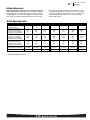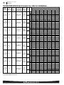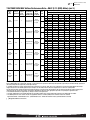
1
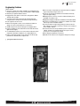
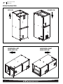
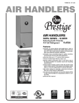
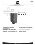
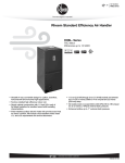
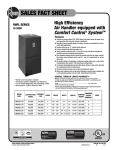
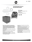
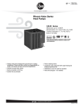
Air
Air Handlers
RHLP Series
Rheem Air Handlers
RHLP- Standard Efficiency
X-13 (ECM) Motor
• RHLP features an X-13 (ECM) motor which provides enhanced
SEER performance with most Rheem outdoor units.
• 11/2 ton [5.3 kW] through 5 ton [17.6 kW] models are between
421/2 to 551/2 inches [1080 to 1410 mm] tall and 22 inches
[559 mm] deep.
• Versatile 4-way convertible design for upflow, downflow, horizontal left and horizontal right applications.
• Factory-installed high efficiency indoor coil.
• All models meet or exceed 330 to 400 CFM [156 to 189 L/s]
per ton at .3 inches [.7 kPa] of external static pressure.
• Enhanced airflow up to .7" external static pressure.
• Sturdy construction with 1.0 inch [.24 kPa] of reinforced foil
faced jacket insulation for excellent thermal and sound
insulation.
• Field-installed auxiliary electric heater kits provide exact heat
for indoor comfort. Kits include circuit breakers which meet UL
and cUL requirements for service disconnect.
• Suitable for R-410A or R-22 Refrigerants with piston change.
FORM NO. H11-549
Air
Table of Contents
RHLP Series
TABLE OF CONTENTS
Engineering Features ......................................................................................3
Model Number Identification ............................................................................4
Dimensional Data............................................................................................5
Airflow Directional Data ..................................................................................6
Airflow Performance Data ............................................................................7-9
Electrical Data ........................................................................................10-12
Electrical Wiring ............................................................................................13
Limited Warranty ..........................................................................................14
2
Air
Engineering Features
RHLP Series
Engineering Features
RHLP- Series
■
The most compact unit design available, all standard heat air
handler models only 421/2 to 551/2 inches [1079 to 1409 mm] high.
■ Attractive pre-painted cabinet exterior.
■ Rugged wall steel cabinet construction, designed for added
strength and versatility.
■ 1.0" foil faced insulation mechanically retained in blower
compartment for excellent thermal and sound performance.
■ Four leg blower motor mount.
■ Blower housing with controls, motor and blower. Slide out
design for service and maintenance convenience.
■ Traditional open wire element design for heat applications.
■ Field convertible for vertical downflow, horizontal left hand or
right hand air supply.
■ 3 combustible floor base accessories fit all model sizes when
required for downflow installations on combustible floors.
■ Indoor coil design provides low air side pressure drop, high
performance and extremely compact size.
■
Piston on indoor coil provides for operation with air conditioning or heat pump using the same coil.
■ Coils are constructed of aluminum fins bonded to internally
grooved copper tubing.
■ Molded polymer corrosion resistant condensate drain pan is
provided on all indoor coils.
■ Supply duct flanges provided as standard on air handler cabinet.
■ Provisions for field electrical, connections available from either
side or top of the air handler cabinet.
■ Connection point for high voltage wiring is inside the air handler cabinet. Low voltage connection is made on the outside of
the air handler cabinet.
■ Concentric knockouts are provided for power connection to
cabinet. Installer may pull desired hole size up to 2 inches
[51 mm] for 11/2 inch [38 mm] conduit.
■ Front refrigerant and drain connections.
■ Suitable for R-410A or R-22 refrigerants with piston change.
[ ] Designates Metric Conversions
3
Air
Model Number Identification
RHLP Series
Model Number Identification
R
H
L
P
— HM 24 17
J
A
Design Variation
A = 1st Design
Voltage
A = 115/1/60
J = 208/240/1/60
Cabinet Size
17 = 17.5" [431.8 mm] (600-1200 CFM)
21 = 21" [533.4 mm] (1400-1600 CFM)
24 = 24.5" [609.6 mm] (1600-1800 CFM)
Capacity
24 = 18,000/24,000 BTU/H [5.27/7.03 kW]
36 = 30,000/36,000 BTU/H [8.79/10.55 kW]
48 = 42,000/48,000 BTU/H [12.31/14.06 kW]
HM = A/C or HP Multi-Position
(Vertical Upflow/Horizontal Left is the
factory configuration)
Refrigerant /Metering Device
P = R-410A/R-22/Fixed Orifice
L = Standard Efficiency
(X-13 (ECM) Motor)
Classification
H = Air Handler
Rheem
[ ] Designates Metric Conversions
4
Available Models at 115V A Voltage
RHLP-HM2417AA
RHLP-HM3617AA
RHLP-HM4821AA
RHLP-HM4824AA
Available Models at 208/240V J Voltage
RHLP-HM2417JA
RHLP-HM3617JA
RHLP-HM4821JA
RHLP-HM4824JA
• Supply circuit protective devices may be fuses or
“HACR” type circuit breakers.
• Largest motor load is included in single circuit and
multiple circuit.
• If non-standard fuse size is specified, use the next
larger fuse size.
• J Voltage (230V) single-phase air handler is
designed to be used with single or three phase 230
volt power. In the case of connecting 3-phase
power to the air handler terminal block, bring only
two leads to the terminal block. Cap, insulate and
fully secure the third lead.
• The air handlers are shipped from the factory with
the proper indoor coil installed, and cannot be
ordered without a coil.
• The air handlers do not have an internal filter rack.
An external filter rack or other means of filtration is
required.
Air
Dimensional Data
RHLP Series
Unit Dimensions
SUPPLY AIR
ELECTRICAL CONNECTIONS
MAY EXIT TOP OR EITHER SIDE
7/8
[22.2 mm],
HIGH VOLTAGE CONNECTION
13/32 [27.8 mm], 131/32 [50 mm] DIA. KNOCKOUTS.
NOTE: 24 CLEARANCE REQUIRED IN FRONT OF
UNIT FOR FILTER AND COIL MAINTENANCE.
105/16
[262 mm]
W
Return Air Opening Dimensions
A
LOW VOLTAGE CONNECTION
5/8 [15.9 mm] AND 7/8 [22.2 mm] KNOCKOUT
Model
Cabinet Size
Return Air
Opening Width
(Inches)
Return Air Opening
Depth/Length
(Inches)
17
21
24
157/8
193/8
227/8
193/4
193/4
193/4
H
AUXILIARY DRAIN CONNECTION
3/4 [19.1 mm] FEMALE PIPE THREAD (NPT)
HORIZONTAL APPLICATION ONLY
PRIMARY DRAIN CONNECTION
[19.1 mm] FEMALE PIPE THREAD (NPT)
3/4
AUXILIARY DRAIN CONNECTION
3/4 [19.1 mm] FEMALE PIPE THREAD (NPT)
UPFLOW/DOWNFLOW APPLICATION ONLY
191/2 [495 mm]
RETURN AIR
OPENING
2111/16
[551 mm]
LIQUID LINE CONNECTION
COPPER (SWEAT)
VAPOR LINE CONNECTION
COPPER (SWEAT)
UPFLOW UNIT SHOWN:
UNIT MAY BE INSTALLED UPFLOW, DOWNFLOW,
HORIZONTAL RIGHT OR LEFT AIR SUPPLY.
515/16
[151 mm]
41/8
1
[105 mm] 3 /16
[76 mm] 13/16 [48 mm] 11/8 [29 mm]
11/16
[27 mm]
13/8
[35 mm]
213/16
[71 mm]
51/4
[133 mm]
53/8
[136 mm]
[ ] Designates Metric Conversions
( ) Designates Unit with Double Coil Cabinet
Unit Dimensions & Weights
Model
Size
RHLP
Unit
Width
“W” In. [mm]
Unit
Height
“H” In. [mm]
Supply
Duct
“A” In. [mm]
2417
3617
4821
4824
171/2 [445]
171/2 [445]
211/2 [533]
241/2 [622]
421/2 [1080]
421/2 [1080]
501/2 [1282]
551/2 [1410]
161/2 [406]
161/2 [406]
191/2 [495]
231/2 [584]
Air Flow
CFM (Nom.) [L/s]
Lo
Hi
600 [283]
800 [378]
1000 [472]
1200 [566]
1400 [661]
1600 [755]
1600 [755]
—
Unit Weight/Shipping Weight (Lbs.) [kg]
Unit With
Coil (Max. KW)
82/96 [37/44]
92/106 [37/48]
150/166 [68/75]
162/180 [73/81]
5
Air
Airflow Directional Data
RHLP Series
Airflow Directional Data
UPFLOW
HORIZONTAL LEFT
HAND AIRFLOW
6
DOWNFLOW
HORIZONTAL RIGHT
HAND AIRFLOW
Air
Airflow Performance Data
RHLP Series
Airflow Performance
Airflow performance data is based on cooling performance
with a coil and no filter in place. Select performance table for
appropriate unit size, voltage and number of electric heaters to
be used. Make sure external static applied to unit allows operation within the minimum and maximum limits shown in table
below for both cooling and electric heat operation. For optimum blower performance, operate the unit in the .3 [8 mm] to
.7 inches [18 mm] W.C. external static range. Units with coils
should be applied with a minimum of .1 inch [3 mm] W.C.
external static range.
Airflow Operating Limits
Model Cabinet Size
17
17
21
24
Cooling BTUH x 1,000
Cooling Tons Nominal
-018
1.5
-024
2
-030
2.5
-036
3
-042
3.5
-048
4
-048
4
Heat Pump or Air Conditioning
Maximum Heat/Cool CFM [L/s]
(37.5 CFM [18 L/s]/1,000 BTUH)
(450 CFM [212 L/s]/Ton Nominal)
675
[319]
900
[425]
1125
[531]
1350
[637]
1575
[743]
1800
[850]
1800
[850]
Heat Pump or Air Conditioning
Nominal Heat/Cool CFM [L/s]
(33.3 CFM [16 L/s]/1,000 BTUH)
(400 CFM [189 L/s]/Ton Nominal)
600
[283]
800
[378]
1000
[472]
1200
[566]
1400
[661]
1600
[755]
1600
[755]
Heat Pump or Air Conditioning
Minimum Heat/Cool CFM [L/s]
(30.0 CFM [14 L/s]/1,200 BTUH)
(360 CFM [170 L/s]/Ton Nominal)
540
[255]
720
[340]
900
[425]
1080
[510]
1260
[595]
1440
[680]
1440
[680]
Maximum kW Electric Heating
& Minimum Electric Heat CFM [L/s]
13
487 [230]
13
617 [291]
18
814 [384]
18
1054 [497]
20
1171 [553]
25
1502 [709]
25
1502 [709]
Maximum Electric Heat Rise °F [°C]
80 [26.7]
63 [17.2]
66 [18.9]
51 [10.6]
49 [9.4]
50 [10]
50 [10]
[ ] Designates Metric Conversions
7
Air
Airflow Performance Data
RHLP Series
115V/208V/240V/460V Airflow Performance Data—RHLP (X-13 (ECM) Motor)
Model
No.
RHLP
Tonnage
Application
Motor
Speed
From
Factory
Manufacturer Blower Size/
Recommended
Motor
Motor
Air-Flow Range
HP [W]
Speed
(Min/Max) CFM # of Speed
2
-2417
No Heater
1.5 Ton
5
509/681 CFM
[240/321 L/s]
10x6
1/3 HP [249]
5 Speed
3
2
-2417
with 13 kW
Heater
1.5 Ton
5
490/666 CFM
[231/314 L/s]
10x6
1/3 HP [249]
5 Speed
3
4
-2417
No Heater
2 Ton
5
730/651 CFM
[345/307 L/s]
10x6
1/3 HP [249]
5 Speed
5
4
-2417
with 13 kW
Heater
2 Ton
5
711/626CFM
[336/295 L/s]
10x6
1/3 HP [249]
5 Speed
5
X-13 CFM [L/s] Air Delivery/RPM/Watts—115/208/240 Volts
External Static Pressure—Inches W.C. [kPa]
0.1 [.02]
0.2 [.05]
0.3 [.07]
0.4 [.10]
0.5 [.12]
0.6 [.15]
0.7 [.17]
CFM
689 [325]
644 [304]
602 [284]
563 [266]
509 [240]
—
—
RPM
580
633
683
728
781
—
—
Watts
66
84
86
88
91
—
—
CFM
—
—
—
—
681 [321]
644 [304]
603 [285]
RPM
—
—
—
—
835
879
916
Watts
—
—
—
—
136
143
152
CFM
670 [316]
625 [295]
583 [275]
544 [257]
490 [231]
—
—
RPM
608
661
711
756
809
—
—
Watts
75
93
95
47
100
—
—
CFM
—
—
—
—
666 [314]
629 [297]
588 [277]
RPM
—
—
—
—
855
899
936
Watts
—
—
—
—
144
151
160
CFM
875 [413]
839 [396]
804 [379]
762 [360]
730 [345]
—
—
RPM
679
724
765
810
852
—
—
Watts
121
131
135
142
143
—
—
CFM
—
—
—
—
862 [407]
828 [391]
801 [378]
RPM
—
—
—
—
904
940
970
Watts
—
—
—
—
203
215
228
CFM
856 [404]
820 [387]
785 [370]
743 [351]
711 [336]
—
—
RPM
707
752
793
838
880
—
—
Watts
130
140
144
151
152
—
—
CFM
—
—
—
—
837 [395]
803 [379]
776 [366]
RPM
—
—
—
—
924
960
990
Watts
—
—
—
—
211
223
288
935 [441]
—
—
CFM 1093 [516] 1050 [496] 1017 [480] 977 [461]
2
-3617
No Heater
2.5 Ton
5
935/1084 CFM
[441/512 L/s]
10x8
1/2 HP [373]
5 Speed
3
RPM
671
725
764
809
852
—
—
Watts
153
168
174
180
188
—
—
CFM
—
—
—
—
RPM
—
—
—
—
896
936
971
Watts
—
—
—
—
249
257
261
952 [449]
910 [429]
—
—
CFM 1068 [504] 1025 [484] 992 [468]
2
-3617
with 18 kW
Heater
2.5 Ton
5
910/1059 CFM
[429/500 L/s]
10x8
1/2 HP [373]
5 Speed
3
4
-3617
No Heater
3 Ton
5
1130/1275 CFM
[533/602 L/s]
10x8
1/2 HP [373]
5 Speed
5
4
-3617
with 18 kW
Heater
3 Ton
5
1105/1250 CFM
[521/590 L/s]
10x8
1/2 HP [373]
5 Speed
5
[ ] Designates Metric Conversions
8
1084 [512] 1040 [491] 1001 [472]
RPM
711
765
804
849
892
—
—
Watts
164
179
185
191
199
—
—
CFM
—
—
—
—
RPM
—
—
—
—
936
976
1011
Watts
—
—
—
—
260
268
272
CFM 1270 [599] 1237 [584] 1199 [566] 1165 [550] 1130 [533]
—
—
RPM
775
816
846
882
926
—
—
Watts
237
249
259
268
277
—
—
CFM
—
—
—
—
RPM
—
—
—
—
963
999
1029
Watts
—
—
—
—
338
348
363
CFM 1245 [588] 1212 [572] 1174 [554] 1140 [538] 1105 [521]
—
—
RPM
815
856
886
922
966
—
—
Watts
248
260
270
279
288
—
—
CFM
—
—
—
—
RPM
—
—
—
—
1003
1039
1069
Watts
—
—
—
—
349
359
374
1059 [500] 1015 [479] 976 [461]
1275 [602] 1244 [587] 1211 [571]
1250 [590] 1219 [575] 1186 [560]
Air
Airflow Performance Data
RHLP Series
115V/208V/240V/460V Airflow Performance Data—RHLP (X-13 (ECM) Motor) (con’t.)
Model
No.
RHLP
Tonnage
Application
Motor
Speed
From
Factory
Manufacturer Blower Size/
Recommended
Motor
Motor
Air-Flow Range
HP [W]
Speed
(Min/Max) CFM # of Speed
2
-4821
No Heater
3.5 Ton
5
1337/1447 CFM
[631/683 L/s]
10x10
3/4 HP [559]
5 Speed
3
2
-4821
with 20 kW
Heater
3.5 Ton
5
1297/1333 CFM
[612/629 L/s]
10x10
3/4 HP [559]
5 Speed
3
4
-4821
No Heater
4 Ton
5
1535/1654 CFM
[724/781 L/s]
10x10
3/4 HP [559]
5 Speed
5
4
-4821
with 25 kW
Heater
4 Ton
5
1495/1614 CFM
[706/762 L/s]
10x10
3/4 HP [559]
2 Speed
5
2
-4824
No Heater
4 Ton
3
1545/1732 CFM
[729/817 L/s]
11x11
3/4 HP [559]
5 Speed
3
2
-4824
with 25 kW
Heater
4 Ton
3
1505/1692 CFM
[710/798 L/s]
11x11
3/4 HP [559]
5 Speed
3
PSC CFM [L/s] Air Delivery/RPM/Watts—115/208/240 Volts
External Static Pressure—Inches W.C. [kPa]
0.1 [.02]
0.2 [.05]
0.6 [.15]
0.7 [.17]
CFM 1473 [695] 1442 [681] 1401 [661] 1373 [648] 1337 [631]
0.3 [.07]
0.4 [.10]
0.5 [.12]
—
—
RPM
781
825
867
905
949
—
—
Watts
257
271
303
307
315
—
—
CFM
—
—
—
—
RPM
—
—
—
—
987
1034
1065
Watts
—
—
—
—
394
406
405
CFM 1433 [676] 1402 [662] 1361 [642] 1333 [629] 1297 [612]
—
—
RPM
831
875
919
954
989
—
—
Watts
277
295
313
319
325
—
—
CFM
—
—
—
—
RPM
—
—
—
—
1011
1046
1080
Watts
—
—
—
—
350
364
377
CFM 1665 [786] 1631 [770] 1601 [756] 1572 [742] 1535 [724]
—
—
RPM
853
893
934
968
1015
—
—
Watts
351
387
401
406
422
—
—
CFM
—
—
—
—
RPM
—
—
—
—
1036
1078
1095
Watts
—
—
—
—
500
513
523
CFM 1625 [767] 1591 [751] 1561 [737] 1532 [723] 1495 [706]
—
—
RPM
894
932
970
1020
1052
—
—
Watts
389
400
410
430
450
—
—
CFM
—
—
—
—
RPM
—
—
—
—
1085
1090
1105
Watts
—
—
—
—
514
520
530
CFM 1748 [825] 1669 [788] 1639 [773] 1599 [755] 1545 [729]
—
—
RPM
660
698
734
762
795
—
—
Watts
297
311
326
340
353
—
—
CFM
—
—
—
—
RPM
—
—
—
—
840
872
899
Watts
—
—
—
—
448
467
480
CFM 1708 [806] 1629 [769] 1599 [755] 1559 [736] 1505 [710]
—
—
RPM
680
736
760
790
820
—
—
Watts
305
330
341
350
361
—
—
CFM
—
—
—
—
RPM
—
—
—
—
865
890
1014
Watts
—
—
—
—
460
470
481
1447 [683] 1433 [676] 1402 [662]
1333 [629] 1300 [613] 1267 [598]
1654 [781] 1624 [766] 1563 [738]
1614 [762] 1584 [748] 1523 [719]
1732 [817] 1683 [794] 1630 [769]
1692 [798] 1643 [775] 1590 [750]
Notes: X-13 (ECM) motor speed changes.
All X-13 (ECM) motors have 5 speed tabs. Speed tab 1 is for continuous fan. Speed tab 2 (low static) and Speed tab 3 (high static) are for lower tonnage. Speed tab 4
(low static) and Speed tab 5 (high static) are for higher tonnage.
X-13 (ECM) air handlers are always shipped from factory at Speed tab 5, except for -4824, which is set at Speed tab 3. For instance, RHLP-HM2417JA is always
shipped at high static 2-ton airflow (Speed tab 5). To change to 1.5-ton airflow, move the blue wire to Speed tab 2 or 3 on the X-13 (ECM) motor.
The low static Speed tab 2 (lower tonnage) and 4 (higher tonnage) are used for external static below 0.5" WC. The high static Speed tab 3 (lower tonnage) and 5
(higher tonnage) are used for external static exceeding 0.5" WC. Move the blue wire to the appropriate Speed tab as required by the application needs.
• The airflow for continuous fan (Speed tab 1) is always set at 50% of the Speed tab 4.
• The above airflow table lists the airflow information for air handlers without heater and air handler with maximum heater allowed for each model.
• The following formula can be used to calculate the approximate airflow, if a smaller (N kW) than the maximum heater kit is installed.
Approximate Airflow = Airflow without heater – (Airflow without heater – Airflow with maximum heater) x (N kW/maximum heater kW)
[ ] Designates Metric Conversions
9
Air
Electrical Data
RHLP Series
Electrical Data – Blower Motor Only – No Electric Heat
Model
RHLP
Voltage
Application
Phase*
Hertz
1&3
60
1
60
2417
208/240
3617
4821/4824
2417
115
3617
4821/4824
* Blower motors are all single phase motors.
[ ] Designates Metric Conversions
10
HP [W]
RPM
Speeds
Circuit
Amps.
1/3 [249]
1/2 [373]
3/4 [559]
1/3 [249]
1/2 [373]
3/4 [559]
300-1100
300-1100
300-1100
300-1100
300-1100
300-1100
4
4
4
4
4
4
1.6
2.7
3.8
4.8
6.8
8.4
Minimum
Circuit
Ampacity
2.0
4.0
5.0
6.0
9.0
11.0
Maximum
Circuit
Protector
15
15
15
15
15
15
Air
Electrical Data
RHLP Series
Electrical Data – With Electric Heat
Installation of the U.L. Listed original equipment manufacturer provided heater kits listed in the following table is recommended for all
auxiliary heating requirements.
Model
RHLP
2417
Heater
Model
No.
Heater
KW
208/240V
PH/HZ
No.
Elements KW Per
Type Supply Circuit
Single Circuit
Multiple Circuit
Circuit Amps.
Motor
Ampacity
Minimum
Circuit
Ampacity
Maximum
Circuit
Protection
RXBH-1724B03J/RXBH-17A03J
RXBH-1724B05J/RXBH-17A05J
RXBH-1724B07J/RXBH-17A07J
RXBH-1724B10J/RXBH-17A10J
RXBH-1724A13J
2.25/3.0
3.6/4.8
5.4/7.2
7.2/9.6
9.4/12.5
3.1/4.2
6.3/8.3
5.4/7.2
7.2/9.6
9.4/12.5
2.25/3.0
3.6/4.8
5.4/7.2
7.2/9.6
9.4/12.5
3.1/4.2
6.3/8.3
10.8/14.4
3.6/4.8
7.2/9.6
12.8/17.0
4.3/5.7
8.5/11.3
5.4/7.2
7.2/9.6
9.4/12.5
10.8/14.4
12.8/17.0
3.6/4.8
5.4/7.2
7.2/9.6
10.8/14.4
3.6/4.8
7.2/9.6
12.8/17
6.4/8.5
6.4/8.5
14.4/19.2
7.2/9.6
7.2/9.6
18.0/24.0
6.0/8.0
6.0/8.0
6.0/8.0
5.4/7.2
7.2/9.6
10.8/14.4
12.8/17.0
14.4/19.2
7.2/9.6
7.2/9.6
18.0/24.0
9.0/12.0
9.0/12.0
1/60
1/60
1/60
1/60
1/60
1/60
1/60
3/60
3/60
3/60
1/60
1/60
1/60
1/60
1/60
1/60
1/60
1/60
1/60
1/60
1/60
1/60
1/60
3/60
3/60
3/60
3/60
3/60
1/60
1/60
1/60
1/60
1/60
1/60
1/60
1/60
1/60
1/60
1/60
1/60
1/60
1/60
1/60
1/60
3/60
3/60
3/60
3/60
3/60
3/60
3/60
3/60
3/60
3/60
1 - 3.0
1 - 4.8
2 - 3.6
2 - 4.8
3-4.17
1-4.17
2-4.17
3 - 2.4
3 - 3.2
3 - 4.17
1 - 3.0
1 - 4.8
2 - 3.6
2 - 4.8
3-4.17
1-4.17
2-4.17
3-4.8
1 - 4.8
2 - 4.8
3-5.68
1-5.68
2 - 5.68
3 - 2.4
3 - 3.2
3 - 4.17
3 - 4.8
3-5.68
1 - 4.8
2 - 3.6
2 - 4.8
3-4.8
1 - 4.8
2 - 4.8
4-4.26
2 - 4.26
2 - 4.26
4-4.8
2 - 4.8
2 - 4.8
6-4.0
2 - 4.0
2 - 4.0
2 - 4.0
3 - 2.4
3 - 3.2
3 - 4.8
3-2.84
3-3.2
3 - 3.2
3 - 3.2
6-4.0
3 - 4.0
3 - 4.0
SINGLE
SINGLE
SINGLE
SINGLE
SINGLE
MULTIPLE CKT 1
MULTIPLE CKT 2
SINGLE
SINGLE
SINGLE
SINGLE
SINGLE
SINGLE
SINGLE
SINGLE
MULTIPLE CKT 1
MULTIPLE CKT 2
SINGLE
MULTIPLE CKT 1
MULTIPLE CKT 2
SINGLE
MULTIPLE CKT 1
MULTIPLE CKT 2
SINGLE
SINGLE
SINGLE
SINGLE
SINGLE
SINGLE
SINGLE
SINGLE
SINGLE
MULTIPLE CKT 1
MULTIPLE CKT 2
SINGLE
MULTIPLE CKT 1
MULTIPLE CKT 2
SINGLE
MULTIPLE CKT 1
MULTIPLE CKT 2
SINGLE
MULTIPLE CKT 1
MULTIPLE CKT 2
MULTIPLE CKT 3
SINGLE
SINGLE
SINGLE
SINGLE
SINGLE
MULTIPLE CKT 1
MULTIPLE CKT 2
SINGLE
MULTIPLE CKT 1
MULTIPLE CKT 2
10.8/12.5
17.3/20.0
26.0/30.0
34.6/40.0
45.1/52.1
15.0/17.4
30.1/34.7
15.0/17.3
20.0/23.1
26.1/30.1
10.8/12.5
17.3/20.0
26.0/30.0
34.6/40.0
45.1/52.1
15.0/17.4
30.1/34.7
51.9/60.0
17.3/20.0
34.6/40.0
61.6/70.8
20.5/23.6
41.1/47.2
15.0/17.3
20.0/23.1
26.1/30.1
30.0/34.6
35.5/41.0
17.3/20.0
26.0/30.0
34.6/40.0
51.9/60.0
17.3/20.0
34.6/40.0
61.6/70.8
30.8/35.4
30.8/35.4
69.2/80
34.6/40.0
34.6/40.0
86.4/99.9
28.8/33.3
28.8/33.3
28.8/33.3
15.0/17.3
20.0/23.1
30.0/34.6
35.6/41.0
40.0/46.2
20.0/23.1
20.0/23.1
50.0/57.8
25.0/28.9
25.0/28.9
1.6
1.6
1.6
1.6
1.6
1.6
0
1.6
1.6
1.6
2.7
2.7
2.7
2.7
2.7
2.7
0
2.7
2.7
0
2.7
2.7
0
2.7
2.7
2.7
2.7
2.7
3.8
3.8
3.8
3.8
3.8
0.0
3.8
3.8
0.0
3.8
3.8
0.0
3.8
3.8
0.0
0.0
3.8
3.8
3.8
3.8
3.8
3.8
0.0
3.8
3.8
0.0
16/18
24/27
35/40
46/52
59/68
21/24
38/44
21/24
27/31
35/40
17/19
25/29
36/41
47/54
60/69
23/26
38/44
69/79
25/29
44/50
81/92
29/33
52/59
23/25
29/33
36/41
41/47
48/55
27/30
38/43
48/55
70/80
27/30
44/50
82/94
44/49
39/45
92/105
48/55
44/50
113/130
41/47
36/42
36/42
24/27
30/34
43/48
50/56
55/63
30/34
25/29
68/77
36/41
32/37
20/20
25/30
35/40
50/60
60/70
25/25
40/45
25/25
30/35
35/40
20/20
25/30
40/45
50/60
60/70
25/30
40/45
70/80
25/30
45/50
90/100
30/35
60/60
25/25
30/35
40/45
45/50
50/60
30/30
40/45
50/60
70/80
30/30
45/50
90/100
45/50
40/45
100/110
50/60
45/50
125/150
45/50
40/45
40/45
25/30
30/35
45/50
50/60
60/70
30/35
25/30
70/80
40/45
35/40
RXBH-1724A13J
RXBH-1724A07C
RXBH-1724A10C
RXBH-1724A13C
RXBH-1724A03J
RXBH-1724A05J
RXBH-1724A07J
RXBH-1724A10J
RXBH-1724A13J
RXBH-1724A13J
RXBH-1724A15J
RHLP
3617
RXBH-1724A15J
RXBH-1724A18J
RXBH-1724A18J
RXBH-1724A07C
RXBH-1724A10C
RXBH-1724A13C
RXBH-1724A15C
RXBH-1724A18C
RXBH-1724B05J/RXBH-24A05J
RXBH-1724B07J/RXBH-24A07J
RXBH-1724B10J/RXBH-24A10J
RXBH-1724A15J
RXBH-1724A15J
RXBH-1724A18J
RXBH-1724A18J
RXBH-24A20J
RXBH-24A20J
RHLP
4821
RXBH-24A25J
RXBH-24A25J
(4-ton only)
RXBH-1724A07C
RXBH-1724A10C
RXBH-1724A15C
RXBH-1724A18C
RXBH-24A20C*
RXBH-24A20C
RXBH-24A25C*
RXBH-24A25C
(4-ton only)
11
Air
Electrical Data
RHLP Series
Electrical Data – With Electric Heat (con’t.)
Installation of the U.L. Listed original equipment manufacturer provided heater kits listed in the following table is recommended for all
auxiliary heating requirements.
Model
Heater
Model
No.
Heater
KW
208/240V
PH/HZ
No.
Elements KW Per
Type Supply Circuit
Single Circuit
Multiple Circuit
Circuit Amps.
Motor
Ampacity
Minimum
Circuit
Ampacity
Maximum
Circuit
Protection
RXBH-172405J
RXBH-172407J
RXBH-172410J
RXBH-172415J
RXBH-172415J
3.6/4.8
5.4/7.2
7.2/9.6
10.8/14.4
3.6/4.8
3.6/4.8
7.2/9.6
12.8/17
6.4/8.5
6.4/8.5
14.4/19.2
7.2/9.6
7.2/9.6
18.0/24.0
6.0/8.0
6.0/8.0
6.0/8.0
5.4/7.2
7.2/9.6
10.8/14.4
12.8/17.0
14.4/19.2
7.2/9.6
7.2/9.6
18.0/24.0
9.0/12.0
9.0/12.0
1/60
1/60
1/60
1/60
1/60
1/60
1/60
1/60
1/60
1/60
1/60
1/60
1/60
1/60
1/60
1/60
1/60
3/60
3/60
3/60
3/60
3/60
3/60
3/60
3/60
3/60
3/60
1 - 4.8
2 - 3.6
2 - 4.8
3 - 4.8
1 - 4.8
1 - 4.8
2 - 4.8
4 - 4.26
2 - 4.26
2 - 4.26
4 - 4.8
2 - 4.8
2 - 4.8
6 - 4.0
2 - 4.0
2 - 4.0
2 - 4.0
3 - 2.4
3 - 3.2
3 - 4.8
3 - 2.84
3 - 3.2
3 - 3.2
3 - 3.2
6 - 4.0
3 - 4.0
3 - 4.0
SINGLE
SINGLE
SINGLE
SINGLE
MULTIPLE CKT 1
MULTIPLE CKT 1
MULTIPLE CKT 2
SINGLE
MULTIPLE CKT 1
MULTIPLE CKT 2
SINGLE
MULTIPLE CKT 1
MULTIPLE CKT 2
SINGLE
MULTIPLE CKT 1
MULTIPLE CKT 2
MULTIPLE CKT 3
SINGLE
SINGLE
SINGLE
SINGLE
SINGLE
MULTIPLE CKT 1
MULTIPLE CKT 2
SINGLE
MULTIPLE CKT 1
MULTIPLE CKT 2
17.3/20.0
26.0/30.0
34.6/40.0
51.9/60.0
17.3/20.0
17.3/20.0
34.6/40.0
61.6/70.8
30.8/35.4
30.8/35.4
69.2/80
34.6/40.0
34.6/40.0
86.4/99.9
28.8/33.3
28.8/33.3
28.8/33.3
15.0/17.3
20.0/23.1
30.0/34.6
35.6/41.0
40.0/46.2
20.0/23.1
20.0/23.1
50.0/57.8
25.0/28.9
25.0/28.9
3.8
4.6
4.6
4.6
4.6
4.6
0
4.6
4.6
0
4.6
4.6
0
4.6
4.6
0
0
4.6
4.6
4.6
4.6
4.6
4.6
0
4.6
4.6
0
27/30
39/44
49/56
71/81
28/31
28/31
44/50
83/95
45/50
39/45
93/106
49/56
44/50
114/131
42/48
36/42
36/42
25/28
31/35
44/49
51/57
56/64
31/35
25/29
69/78
37/42
32/37
30/30
40/45
50/60
80/90
30/35
30/35
45/50
90/100
45/50
40/45
100/110
50/60
45/50
125/150
45/50
40/45
40/45
25/30
35/35
45/50
60/60
60/70
35/35
25/30
70/80
40/45
35/40
RXBH-172415J
RXBH-172418J
RXBH-172418J
RXBH-24A20J
RXBH-24A20J
RHLP
4824
RXBH-24A25J
RXBH-24A25J
RXBH-172407C
RXBH-172410C
RXBH-172415C
RXBH-172418C
RXBH-24A20C*
RXBH-24A20C
RXBH-24A25C*
RXBH-24A25C
* Values only. No single point kit available.
• Supply circuit protective devices may be fused or “HACR” type circuit breakers.
• If non-standard fuse size is specified, use next size larger standard fuse size.
• If the kit is listed under both single and multiple circuits, the kit is shipped from factory as multiple
circuits. For single phase application, Jumper bar kit RXBJ-A21 and RXBJ-A31 can be used to convert
multiple circuits to a single supply circuit. Refer to Accessory Section for details.
• Largest motor load is included in single circuit or circuit 1 of multiple circuit.
• Heater loads are balanced on 3 PH. models with 3 or 6 heaters only.
12
• Electric heater BTUH - (heater watts + motor watts) x 3.414 (see airflow table for motor watts.)
• No electrical heating elements are permitted to be used with “A” voltage (115V) air handler.
• J voltage (208/240V) single phase air handler is designed to be used with single or three phase
208/240V electric heaters. In the case of connecting 3 phase power to air handler terminal block
without the heater, bring only two leads to terminal block. Cap, insulate and fully secure the
third lead.
• Do not use 480V electrical heaters on 208/240V air handlers.
• Do not use 208/240V electrical heaters on 480V air handlers.
Air
Electrical Wiring
RHLP Series
Electrical Wiring
Power Wiring
Grounding
• Field wiring must comply with the National Electrical Code
(C.E.C. in Canada) and any applicable local ordinance.
• This product must be sufficiently grounded in accordance with
National Electrical Code (C.E.C. in Canada) and any applicable
local ordinance.
• Supply wiring must be 75°C minimum copper conductors only.
• See electrical data for product Ampacity rating and Circuit
Protector requirement.
• A grounding lug is provided.
Accessories-Kits—Parts
• Combustible Floor Base RXHB-
• Auxiliary Electric Heater Kits RXBHHeater Kits include circuit breakers which meet UL and cUL
requirements for service disconnect. See the Electric Heat
Electrical Data in this specification sheet for specific Heater Kit
Model numbers.
Combustible Floor
Base Model Number
RXHB-17
RXHB-21
RXHB-24
Model Cabinet Size
17
21
24
• Jumper Bar Kit 3 Ckt. to 1 Ckt. RXBJ-A31 is used to convert
single phase multiple three circuit units to a single supply
circuit. Kit includes cover and screw for line side terminals.
• Jumper Bar Kit 2 Ckt. to 1 Ckt. RXBJ-A21 is used to convert
single phase multiple two circuit units to a single supply circuit.
Kit includes cover and screw for line side terminals.
• Note: No jumper bar kit is available to convert three phase
multiple two circuit units to a single supply circuit.
• Horizontal Adapter Kit RXHHThis horizontal adapter kit is used to convert Upflow/Downflow
only models to horizontal flow. See the following table to order
proper horizontal adapter kit.
Coil Model
2414
2417
3617
4821/4824
Horizontal Adapter Kit
Horizontal Adapter Kit
Model Number (Single Qty.) Model Number (10-Pack Qty.)
RXHH-A01
RXHH-A01 x 10
RXHH-A02
RXHH-A02 x 10
RXHH-A03
RXHH-A03 x 10
RXHH-A04
RXHH-A04 x 10
• Auxiliary Horizontal Overflow Pan Accessory RXBMNominal Cooling
Capacity-Tons
11/2 - 3
31/2 - 4
Auxiliary Horizontal Overflow Pan
Accessory Model Number
RXBM-AC48
RXBM-AC61
• External Filter Rack RXHF-B17, B21, B24
Model Cabinet Size
17
21
24
Filter Size In. [mm]
16 x 20 [406 x 508]
20 x 20 [508 x 508]
25 x 20 [635 x 508]
• External Filter Base RXHFModel Cabinet Size
17
21
24
Filter Size In. [mm]
16 x 20 [406 x 508]
20 x 20 [508 x 508]
25 x 20 [635 x 508]
Part Number*
RXHF-17
RXHF-21
RXHF-24
A
15.70
19.20
22.70
B
17.5
21.0
25.5
*Accommodates 1" or 2" filter
Part Number*
RXHF-B17
RXHF-B21
RXHF-B24
A
16.90
20.40
25.00
B
20.77
20.77
21.04
[ ] Designates Metric Conversions
*Accommodates 1" filter
RXHF-B
RXHF-
11/2⬙
[38 mm]
B
B
A
A
13
Air
Limited Warranty
RHLP Series
GENERAL TERMS OF LIMITED WARRANTY*
Rheem will furnish a replacement for any part of this product
which fails in normal use and service within the applicable
periods stated, in accordance with the terms of the limited
warranty.
14
Conditional Parts (Registration Required) ..........Ten (10) Years
*For complete details of the Limited and Conditional Warranties, including
applicable terms and conditions, contact your local contractor or the
Manufacturer for a copy of the product warranty certificate.
Air
Notes
RHLP Series
15
The new degree of comfort.™
In keeping with its policy of continuous progress and product improvement, Rheem reserves the right to make changes without notice.
Rheem Heating, Cooling & Water Heating • P.O. Box 17010
Fort Smith, Arkansas 72917 • www.rheem.com
Rheem Canada Ltd./Ltée • 125 Edgeware Road, Unit 1
Brampton, Ontario • L6Y 0P5
PRINTED IN U.S.A 11/12 QG FORM NO. H11-549