1
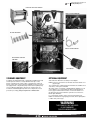
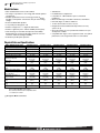
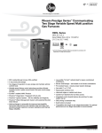
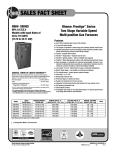
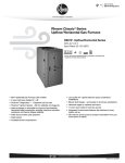
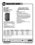
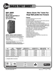
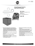
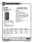
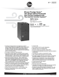
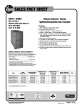
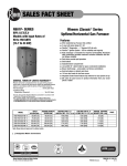
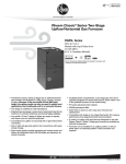
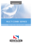
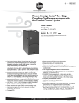
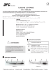
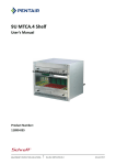
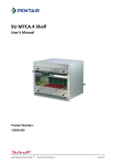
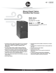
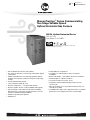
Air
Gas Furnaces
R802V (UF/HZ) Series
Rheem Prestige™ Series Communicating
Two-Stage Variable Speed
Upflow/Horizontal Gas Furnace
R802V- Upflow/Horizontal Series
80% A.F.U.E.†
Input Rates 50-125 kBTU
✝ A.F.U.E. (Annual Fuel Utilization Efficiency) calculated in accordance with
Department of Energy test procedures.
• 80% residential Gas Furnace CSA certified
• Two stages of operation to save energy and maintain optimal
comfort level.
• Variable speed blower motor technology provides ultimate
humidity control quieter sound levels and year round energy
savings
• EcoNet enabled HVAC product
• 3 way multi poise design UF / HZ
• PlusOne™ Diagnostics — 7 Segment LED all units
• PlusOne™ Ignition System – DSI for reliability and longevity
• Heat exchanger is removable for improved serviceability.
Aluminized steel construction provides maximum corrosion
resistance and thermal fatigue reliability.
• Solid doors provide quiet operation
• Solid bottom
• Insulated blower compartment
• Low profile 34" cabinet ideal for space constrained
installations
• Blower shelf design – serviceable in all furnace orientations
• Hemmed edges on cabinets and doors
• 1/4 turn door knobs for tool less access
• Integrated Control board features dip switches for easy
system set up
• QR code for quick access to product information from your
smart phone or tablet
• Compatible with single or two stage thermostats. For optimal
performance a two stage thermostat is recommended.
FORM NO. G11-546 REV. 1
Air
Table of Contents
R802V (UF/HZ) Series
TABLE OF CONTENTS
Standard & Optional Equipment ......................................................................3
Model Features/Physical Data & Specifications..................................................4
Model Number Identification ............................................................................5
Dimensional Data ........................................................................................6-7
Blower Performance Data ................................................................................8
Accessories....................................................................................................9
Limited Warranty ..........................................................................................10
2
Air
Standard & Optional Equipment
R802V (UF/HZ) Series
PATENTED HEAT EXCHANGER
DRAFT INDUCER MOTOR
IN-SHOT BURNERS
DIRECT SPARK IGNITOR
INTEGRATED FURNACE
CONTROL
ECM MOTOR
STANDARD EQUIPMENT
OPTIONAL EQUIPMENT
Completely assembled and wired; 2 speed induced draft blower; high
and low pressure switches; 2 stage redundant main gas control;
blower compartment door safety switch; solid state time on/time off
blower control; limit control; transformer; ECM blower motor. Furnaces
are equipped with cooling/heating relay and transformer (50VA) ready
for air conditioning applications. (Please note: a thermostat is not
included as standard equipment.) Flame sensor diagnostics; fusedprotection (secondary), 3rd speed option for continuous fan.
Side and bottom filter frame assembly. 4" Flue Adapter
NOTE: Furnace is not listed for use with fuels other than natural or L.P.
(propane) gas.
The complete terms of limited and other warranties are available at our
sales office, or through local installer.
All models can be converted by a qualified Rheem distributor or local
service dealer to use L.P. (propane) gas without changing burners.
Factory approved kits must be used to convert from natural to L.P.
(propane) gas and may be ordered as optional accessories from a
Rheem parts distributor.
For L.P. (propane) operation, refer to Conversion Kit Index Form.
NOTE: For natural and L.P. (propane) gas models, direct spark ignition
is 100% safety lockout type.
WARNING
THIS FURNACE IS NOT APPROVED
OR RECOMMENDED
FOR USE IN MOBILE HOMES
3
Air
Model Features/Physical Data & Specifications
R802V (UF/HZ) Series
Model Features
• 80% residential Gas Furnace CSA certified
• Two stages of operation to save energy and maintain optimal
comfort level.
• Variable speed blower motor technology provides ultimate
humidity control quieter sound levels and year round energy
savings
• EcoNet enabled HVAC product
• 3 way multi poise design UF / HZ
• PlusOne™ Diagnostics — 7 Segment LED all units
• PlusOne™ Ignition System – DSI for reliability and longevity
• Heat exchanger is removable for improved serviceability.
Aluminized steel construction provides maximum corrosion
resistance and thermal fatigue reliability.
• Solid doors provide quiet operation
• Solid bottom
• Insulated blower compartment
• Low profile 34" cabinet ideal for space constrained
installations
• Blower shelf design serviceable in all furnace orientations
• Hemmed edges on cabinets and doors
• 1/4 turn door knobs for tool less access
• Integrated Controls board features dip switches for easy
system set up
• QR code for quick access to product information from your
smart phone or tablet
• Compatible with single or two stage thermostats. For optimal
performance a two stage thermostat is recommended.
Physical Data and Specifications
MODEL NUMBERS R802V SERIES
R802VA050317M*A
R802VA075317M*A
R802VA075421M*A
R802VA100521M*A
R802VA125524M*A
High Input-BTU/Hr [kW] ➁
Heating Capacity BTU/Hr [kW] ➀
Low Input BTU/Hr [kW] ➁
Heating Capacity BTU/Hr [kW] ➀
Heat Ext. Static Pressure [kPa]
50,000 [15]
40,000 [12]
35,000 [10]
28,000 [8]
.10 [.025]
75,000 [22]
60,000 [18]
52,500 [15]
42,000 [12]
.12 [.029]
75,000 [22]
60,000 [18]
52,500 [15]
42,000 [12]
.12 [.029]
100,000 [29]
80,000 [23]
70,000 [20]
56,000 [16]
.15 [.037]
125,000 [37]
100,000 [29]
87,500 [25]
70,000 [20]
.20 [.05]
Blower (D x W) [mm]
11 x 7
[279 x 178]
11 x 7
[279 x 178]
11 x 7
[279 x 178]
11 x 10
[279 x 254]
11 x 10
[279 x 254]
Motor H.P.
Type [W]
Motor Full Load Amps
1/2
ECM
[373]
1/2
ECM
[373]
3/4
ECM
[560]
3/4
ECM
[560]
3/4
ECM
[560]
7.7
7.7
9.6
9.6
9.6
Cooling CFM @ Rating Point
[L/s]
1250
[590]
1650
[780]
1800
[850]
1750
[825]
1900
[900]
Max. E.S.P. (In. W.C.) [kPa]
1.0 [.249]
1.0 [.249]
1.0 [.249]
1.0 [.249]
1.0 [.249]
Temperature Rise Range °F
[°C]–High Input
25-55
[13.9-30.6]
25-55
[13.9-30.6]
25-55
[13.9-30.6]
35-65
[19.4-36.1]
35-65
[19.4-36.1]
Temperature Rise Range °F
[°C]–Low Input
20-50
[12.8-29.4]
20-50
[12.8-29.4]
20-50
[12.8-29.4]
30-60
[18.3-35]
30-60
[18.3-35]
155
[68.3]
155
[68.3]
165
[73.8]
180
[82.2]
180
[82.2]
125
[57]
125
[57]
140
[64]
140
[64]
150
[68]
80.0%
80.0%
80.0%
Max. Outlet Air Temp. °F
[°C]
Approx. Shipping Weight (Lbs.)
[kg]
AFUE ➀
80.0%
80.0%
NOTES: All models are 115V, 60HZ, 1 Ph. Gas connection size for all models is 1/2" [12 mm] N.P.T.
➀ In accordance with D.O.E. test procedures.
➁ See Conversion Kit Index Form for high altitude derate.
* S = Standard, X = Low Nox
[ ] Designates Metric Conversions
4
Air
Model Number Identification
R802V (UF/HZ) Series
Model Number Identification
R
80
2
V
A
075
4
17
M
S
A
Rheem
80 =
80% AFUE
2 = Two Stage
V = Variable
Speed
ECM
Design Series
A = 1st Design
Input
BTU/HR [kW]
050 = 50,000 [15]
075 = 75,000 [22]
100 = 100,000 [29]
125 = 125,000 [37]
3 = Up to
3 Ton
4 = 21/2 to
4 Ton
5 = 31/2 to
5 Ton
Cabinet
Width
17 = 17.5"
21 = 21".0
24 = 24.5"
M = Multi
X = Low NOx
S = Standard
RevisionMarketing
(A – First Time
Release)
[ ] Designates Metric Conversions
5
Air
Dimensional Data
R802V (UF/HZ) Series
Upflow Application
Dimensional Data: Upflow Model
MODEL
R802V-
A
B
C
D
E
F
LEFT
SIDE
050, 075317
075421, 100
125
171/2 [445]
211/2 [533]
241/2 [622]
1611/32 [415]
1927/32 [504]
2311/32 [593]
123/8 [314]
141/8 [359]
157/8 [403]
➀
➀
➀
151/2 [381]
181/2 [470]
221/2 [559]
21/2 [64]
21/2 [64]
21/2 [64]
0
0
0
REDUCED CLEARANCE (IN.) [mm]
SHIP
WGTS.
RIGHT
BACK
TOP
FRONT
VENT
(LBS.) [kg]
SIDE
3 [76] ➁
0
1 [25] 3 [76] 6 [152] ➂ 125 [57]
0
0
1 [25] 3 [76] 6 [152] ➂ 140 [64]
0
0
1 [25] 3 [76] 6 [152] ➂ 150 [68]
NOTES: ➀ May require a 3" [76 mm] to 4" [102 mm] or 3" [76 mm] to 5" [127 mm] adapter.
➁ May be 0" [0 mm] with type B vent.
➂ May be 1" [25 mm] with type B vent.
Furnaces must be vented in accordance with the National Fuel Gas Code, ANSI Z223.1 in accordance with local codes.
[ ] Designates Metric Conversions
6
Air
Dimensional Data
R802V (UF/HZ) Series
Horizontal Application
WARNING
THIS FURNACE IS NOT APPROVED
OR RECOMMENDED FOR INSTALLATION
ON ITS BACK, WITH ACCESS DOORS
FACING UPWARDS.
Dimensional Data: Horizontal Model
MODEL
R802V-
A
B
C
D
E
F
LEFT
SIDE
050, 075317
075421, 100
125
171/2 [445]
211/2 [533]
241/2 [622]
1611/32 [415]
1927/32 [504]
2311/32 [593]
123/8 [314]
141/8 [359]
157/8 [403]
➀
➀
➀
151/2 [381]
181/2 [470]
221/2 [559]
21/2 [64]
21/2 [64]
21/2 [64]
0
0
0
REDUCED CLEARANCE (IN.) [mm]
SHIP
WGTS.
RIGHT
BACK
TOP
FRONT
VENT
(LBS.) [kg]
SIDE
3 [76] ➁
0
1 [25] 3 [76] 6 [152] ➂ 125 [57]
0
0
1 [25] 3 [76] 6 [152] ➂ 140 [64]
0
0
1 [25] 3 [76] 6 [152] ➂ 150 [68]
NOTES: ➀ May require a 3" [76 mm] to 4" [102 mm] or 3" [76 mm] to 5" [127 mm] adapter.
➁ May be 0" [0 mm] with type B vent.
➂ May be 1" [25 mm] with type B vent.
Furnaces must be vented in accordance with the National Fuel Gas Code, ANSI Z223.1 in accordance with local codes.
[ ] Designates Metric Conversions
7
Air
Blower Performance Data
R802V (UF/HZ) Series
Blower Performance Data
MODEL NUMBER
R802VA050317MSA R802VA075317MSA R802VA075421MSA R802VA100521MSA R802VA125524MSA
SW15 = OFF SW16 = OFF
890
1425
1345
1400
1985
SW15 = ON
790
1200
1100
1250
1700
SW16 = OFF
HIGH
HEATING CFM SW15 = OFF SW16 = ON
TARGET GAS
HEATING
AIRFLOW
TARGET
COOLING/
HEAT-PUMP
AIRFLOW
735
1075
960
1150
1530
SW13 = OFF SW14 = OFF
835
1125
1045
1200
1500
SW13 = ON SW14 = OFF
LOW
HEATING CFM SW13 = OFF SW14 = ON
590
950
865
1050
1275
SW15 = ON
SW16 = ON
DO NOT USE
SW13 = ON
SW14 = ON
510
825
665
950
1150
SW4 = OFF
SW5 = OFF
1200
1200
1600
2000
2000
SW4 = ON
SW5 = OFF
1000
1000
1400
1600
1600
SW5 = ON
800
800
1200
1400
1400
SW4 = ON
SW5 = ON
600
600
1000
1200
1200
SW4 = OFF
SW5 = OFF
900
900
1200
1500
1500
SW4 = ON
LOW
COOLING CFM SW4 = OFF
SW5 = OFF
750
750
1050
1200
1200
SW5 = ON
600
600
900
1050
1050
SW5 = ON
450
450
750
900
900
HIGH
COOLING CFM SW4 = OFF
SW4 = ON
[ ] Designates Metric Conversions
8
DO NOT USE
Air
Accessories
R802V (UF/HZ) Series
FOR HIGH ALTITUDES:
SIDE RETURN FILTER RACK: RXGF-CD
BOTTOM RETURN FILTER RACK FOR
UPFLOW APPLICATION: RXGF-CB
FILTER RACK FILTER SIZES* INCHES [mm]
MODEL
R802V
RXGF-CB
(UPFLOW/
HORIZONTAL)
RXGF-CD
(UPFLOW)
SIDE RETURN
050 & 075317
153/4 x 25
[400 x 635]
153/4 x 25
[400 x 635]
075421 & 100
191/4 x 25
[489 x 635]
153/4 x 25
[400 x 635]
125
223/4 x 25
[578 x 635]
153/4 x 25
[400 x 635]
OPTION CODE FOR HIGH ALTITUDE: U.S.
None required for high altitudes.
HIGH ALTITUDE CONVERSION KITS: U.S.
None required for high altitudes.
80+ HIGH ALTITUDE INSTRUCTIONS
CAUTION: Always follow National Fuel Gas Code (NFGC) guidelines
when converting for high altitudes.
High altitude option codes are not required for these models.
However, the burner orifice size needs to be recalculated and verified
at elevations above 2000 ft. See Installation Instructions for more
information.
[ ] Designates Metric Conversions
INDOOR COIL CASINGS
ECONET CONTROL
MODEL
NUMBER
RECOMMENDED COMMUNICATING FURNACE CONTROL
RXBC-D17AI
RXBC-D21AI
RXBC-D21BI
RXBC-D24AI
4" FLUE ADAPTER: RXGW-C01
WARNING: IMPORTANT NOTICE
A SOLID METAL BASE PLATE (SEE TABLE) MUST BE IN PLACE WHEN THE
FURNACE IS INSTALLED WITH SIDE AIR RETURN DUCTS. FAILURE TO
INSTALL A BASE PLATE COULD CAUSE PRODUCTS OF COMBUSTION TO
BE CIRCULATED INTO THE LIVING SPACE AND CREATE POTENTIALLY
HAZARDOUS CONDITIONS.
FURNACE
WIDTH
IN. [mm]
171/2 [445]
211/2 [533]
241/2 [622]
SOLID
BOTTOM
KIT NO.
RXGB-D17
RXGB-D21
RXGB-D24
BASE
PLATE NO.
AE-61874-02
AE-61874-03
AE-61874-04
BASE
PLATE SIZE
IN. [mm]
151/8 x 239/16 [384 x 598]
185/8 x 239/16 [473 x 598]
255/8 x 239/16 [651 x 598]
RETST600SYS
CONTRACTOR BENEFITS:
• Auto/Self Configuration
• Day-at-a-glance scheduling, with programmable fan
• Intuitive wiring connections
• Dual fuel ready
• Automatically optimizes airflow
• System status & mode information
• Complete diagnostic information on display
HOMEOWNER BENEFITS:
• Large, easy to read icons and characters
• Auto-mode control
• Smart recovery
• Continuous Fan Mode (5 speeds)
• Humidity Control
• Water heater, pool heater integration* (check model compatibility)
*ECONET CONTROL ACCESSORIES:
Wall Plate = RCPN-AMC08
Face Plate = RETSTFPL
IMPORTANT: Existing Comfort Control 2 System Condensing Units &
Heat Pumps are compatible with EcoNet when matched with a
R802V Gas Furnace and with an EcoNet Translator (RETRN620CC2)
installed on the Comfort Control 2 System control board.
*Available through PROSTOCK®.
9
Air
Limited Warranty
R802V (UF/HZ) Series
GENERAL TERMS OF LIMITED WARRANTY*
Rheem will furnish a replacement for any part of this product
which fails in normal use and service within the applicable
period stated, in accordance with the terms of the limited
warranty.
*For complete details of the Limited and Conditional Warranties,
including applicable terms and conditions, contact your local contractor
or the Manufacturer for a copy of the product warranty certificate.
10
Parts* ..........................................................Ten (10) Years
Heat Exchanger ........................................Limited Lifetime
Air
Notes
R802V (UF/HZ) Series
11
The new degree of comfort.™
In keeping with its policy of continuous progress and product improvement, Rheem reserves the right to make changes without notice.
Rheem Heating, Cooling & Water Heating • P.O. Box 17010
Fort Smith, Arkansas 72917 • www.rheem.com
Rheem Canada Ltd./Ltée • 125 Edgeware Road, Unit 1
Brampton, Ontario • L6Y 0P5
PRINTED IN U.S.A. 3/15 QG FORM NO. G11-546 REV. 1