1
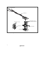
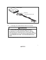
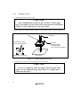
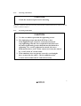
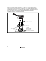
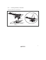
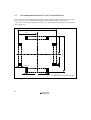
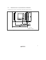
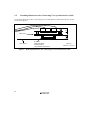
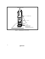
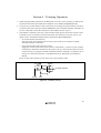
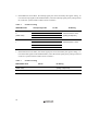
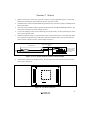
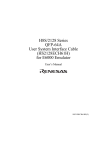
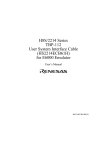
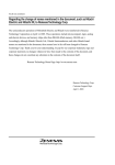
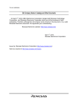
H8S/2338 Series QFP-144 User System Interface Cable (HS2338ECH61H) for E6000 Emulator User’s Manual HS2338ECH61HE(D) Cautions 1. Renesas neither warrants nor grants licenses of any rights of Renesas’s or any third party’s patent, copyright, trademark, or other intellectual property rights for information contained in this document. Renesas bears no responsibility for problems that may arise with third party’s rights, including intellectual property rights, in connection with use of the information contained in this document. 2. Products and product specifications may be subject to change without notice. Confirm that you have received the latest product standards or specifications before final design, purchase or use. 3. Renesas makes every attempt to ensure that its products are of high quality and reliability. However, contact Renesas’s sales office before using the product in an application that demands especially high quality and reliability or where its failure or malfunction may directly threaten human life or cause risk of bodily injury, such as aerospace, aeronautics, nuclear power, combustion control, transportation, traffic, safety equipment or medical equipment for life support. 4. Design your application so that the product is used within the ranges guaranteed by Renesas particularly for maximum rating, operating supply voltage range, heat radiation characteristics, installation conditions and other characteristics. Renesas bears no responsibility for failure or damage when used beyond the guaranteed ranges. Even within the guaranteed ranges, consider normally foreseeable failure rates or failure modes in semiconductor devices and employ systemic measures such as fail-safes, so that the equipment incorporating Renesas product does not cause bodily injury, fire or other consequential damage due to operation of the Renesas product. 5. This product is not designed to be radiation resistant. 6. No one is permitted to reproduce or duplicate, in any form, the whole or part of this document without written approval from Renesas. 7. Contact Renesas’s sales office for any questions regarding this document or Renesas semiconductor products. Preface Thank you for purchasing this user system interface cable (HS2338ECH61H) for the Renesas’s original microcomputer H8S/2338 series. The HS2338ECH61H is a user system interface cable that connects an H8S/2338 series E6000 emulator (HS2338EPI61H; hereinafter referred to as the emulator) to the IC socket for a QFP-144 package (package code: FP-144) for the H8S/2338 series MCU on the user system. i Contents Section 1 Configuration...................................................................................1 Section 2 Connection Procedures ....................................................................4 2.1 2.2 2.3 2.4 2.5 Connecting User System Interface Cable to Emulator Station ......................................... 4 Connecting User System Interface Cable to User System ................................................ 5 2.2.1 Installing IC Socket ............................................................................................. 6 2.2.2 Inserting Cable Head ........................................................................................... 7 2.2.3 Fastening Cable Head .......................................................................................... 7 2.2.4 Connecting Cable Body to Cable Head ............................................................... 9 Recommended Dimensions for User System Mount Pad ................................................. 10 Dimensions for User System Interface Cable Head.......................................................... 11 Resulting Dimensions after Connecting User System Interface Cable ............................. 12 Section 3 Installing the MCU to the User System.............................................13 Section 4 Verifying Operation...........................................................................15 Section 5 Notice ................................................................................................17 ii Section 1 Configuration CAUTION Use an NQPACK144SD socket (manufactured by Tokyo Eletech Coporation) for the FP-144 package IC socket on the user system. Figure 1 shows the configuration of the HS2338ECH61H user system interface cable for the FP-144 package. 1 To emulator station Cable body Screws (M2 x 10 mm) (for fastening cable head) Screws (M2 x 6 mm) Socket cover Cable head IC socket User system Figure 1 2 HS2338ECH61H User System Interface Cable Table 1 lists the HS2338ECH61H components. Please make sure you have all of these components when unpacking. Table 1 HS2338ECH61H Components No. Component Quantity Remarks Includes flat cable 1 Cable body 1 2 Cable head 1 3 IC socket 1 For the FP-144 package 4 Socket cover 1 For installing an FP-144 packaged MCU 5 Screws (M2 x 10 mm) 4 For fastening cable head 6 Screws (M2 x 6 mm) 4 For installing an FP-144 packaged MCU 7 Guide pins (φ 1 mm) 3 For determining the IC socket location 8 Screwdriver 1 For tightening screws 9 Documentation 1 User’s manual for HS2338ECH61H (this manual) 3 Section 2 Connection Procedures 2.1 Connecting User System Interface Cable to Emulator Station WARNING Always switch OFF the user system and the emulator product before the USER SYSTEM INTERFACE CABLE is connected to or removed from any part. Before connecting, make sure that pin 1 on both sides are correctly aligned. Failure to do so will damage the user system and the emulator product or will result in PERSONAL INJURY. The USER PROGRAM will be LOST. To connect the cable body to the emulator station, follow the instructions below. 1. Make sure the user system and emulator station are turned off. CAUTION When connecting or removing the user system interface cable, apply force only in the direction suitable for connection or removal, while making sure not to bend or twist the cable or connectors. Otherwise, the connectors will be damaged. 2. After making sure the direction of the cable body connector is correct, firmly insert the cable body connector into the emulator station socket (figure 2). 4 6 E 0 0 0 Emulator station Cable body User system interface cable Figure 2 2.2 Connecting User System Interface Cable to Emulator Station Connecting User System Interface Cable to User System WARNING Always switch OFF the user system and the emulator product before the USER SYSTEM INTERFACE CABLE is connected to or removed from any part. Before connecting, make sure that pin 1 on both sides are correctly aligned. Failure to do so will damage the user system and the emulator product or will result in PERSONAL INJURY. The USER PROGRAM will be LOST. To connect the cable head to the user system, follow the instructions below. 5 2.2.1 Installing IC Socket 1. Confirming the location of IC socket CAUTION After confirming the location of pin 1 on the IC socket, apply epoxy resin adhesive to the end of the four projections at the bottom of the IC socket, and fasten it to the user system. Use the guide pins provided to determine where to install the IC socket, as shown in figure 3. Pin 1 Guide pins 4 projections to apply epoxy resin adhesive to IC socket (NQPACK144SD manufactured by Tokyo Eletech Corporation) Bottom view of IC socket User system Figure 3 Location Setting of IC Socket 2. Solder the IC socket for a FP-144 package to the user system. CAUTION Be sure to completely solder the leads so that the solder slops gently over the leads and forms solder fillets. (Use slightly more solder than the MCU.) 6 2.2.2 Inserting Cable Head CAUTION Check the location of pin 1 before inserting. Align pin 1 on the IC socket for a FP-144 system interface cable head into the IC socket on the user system, as shown in figure 4. 2.2.3 Fastening Cable Head CAUTION 1. Use the screwdriver provided for tightening screws. 2. The tightening torque must be 0.054 N•m or less. If the applied torque cannot be accurately measured, stop tightening when the force required to turn the screw becomes significantly greater than that needed when first tightening. If a screw is tightened too much, the screw head may break or an IC socket contact error may be caused by a crack in the IC socket solder. 3. If the emulator does not operate correctly, cracks might have occurred in the solder. Check conduction with a tester and re-solder the IC socket if necessary. 7 Fasten the user system interface cable head to the IC socket for an FP-144 package on the user system with the four screws (M2 x 10 mm) provided. Each screw should be tightened a little at a time, alternating between screws on opposing corners. Take special care, such as manually securing the IC socket soldered area, to prevent the soldered IC socket from being damaged by overtightening the screws or twisting the components. Screws (M2 x 10 mm) Cable head IC socket (NQPACK144SD manufactured by Tokyo Eletech Coporation) Pin 1 User system Figure 4 8 Connecting User System Interface Cable to User System 2.2.4 Connecting Cable Body to Cable Head Connect the cable body to the cable head. Cable body Removing Push the remove jig Remove jig Cable head User system Figure 5 Fastening Cable Body 9 2.3 Recommended Dimensions for User System Mount Pad Figure 6 shows the recommended dimensions for the mount pad (footprint) for the user system with an IC socket for an FP-144 package (NQPACK144SD: manufactured by Tokyo Eletech Corporation). Note that the dimensions in figure 6 are somewhat different from those of the actual chip's mount pad. 23.00 ± 0.15 0.50 23.00 ± 0.15 11.50 11.50 2.00 ±0.10 0.50 0.25 (max.) Unit: mm Tolerance: ±0.10 unless otherwise specified Figure 6 10 Recommended Dimensions for Mount Pad 2.4 Dimensions for User System Interface Cable Head The dimensions for the user system interface cable head are shown in figure 7. Unit: mm Tolerance: –0.5 mm Figure 7 Dimensions for User System Interface Cable Head 11 2.5 Resulting Dimensions after Connecting User System Interface Cable The resulting dimensions, after connecting the user system interface cable head to the user system, are shown in figure 8. Cable head User system Figure 8 12 IC socket (NQPACK144SD manufactured by Tokyo Eletech Corporation) Unit: mm Tolerance: –0.5 mm Resulting Dimensions after Connecting User System Interface Cable Section 3 Installing the MCU to the User System CAUTION 1. Check the location of pin 1 before inserting. 2. Use the screwdriver provided for tightening screws. 3. The tightening torque must be 0.054 N•m or less. If the applied torque cannot be accurately measured, stop tightening when the force required to turn the screw becomes significantly greater than that needed when first tightening. If a screw is tightened too much, the screw head may break or an IC socket contact error may be caused by a crack in the IC socket solder. 4. If the MCU does not operate correctly, cracks might have occurred in the solder. Check conduction with a tester and re-solder the IC socket if necessary. Check the location of pin 1 before inserting the MCU into the IC socket on the user system, as shown in figure 9. After inserting the MCU, fasten the socket cover with the provided four screws (M2 x 6 mm). Take special care, such as manually securing the IC socket soldered area, to prevent the IC socket from being damaged by overtightening the screws or twisting the components. 13 Screws (M2 x 6 mm) Socket cover MCU Pin 1 User system Figure 9 14 IC socket (NQPACK144SD manufactured by Tokyo Eleteck Corporation) Installing MCU to User System Section 4 Verifying Operation 1. When using the E6000 emulator for the H8S/2338 series, turn on the emulator according to the procedures described in the E6000 Series Emulator User's Manual (HS2000EPI61HE). 2. Verify the user system interface cable connections by accessing the external memory and ports to check the bus states of the pins with the MEMORY_FILL command (emulator command). If an error is detected, recheck the soldered IC socket and the location of pin 1. 3. The emulator connected to this user system interface cable supports two kinds of clock sources as the MCU clock: an emulator internal clock and an external clock on the user system. For details, refer to the Emulator Supplementary Information (HS2338EPI61HE). To use the emulator internal clock Select the clock in the emulator station as the system clock (φ), by using the CLOCK command (emulator command). To use the external clock on the user system Supply the external clock from the user system to the emulator. Connect a crystal oscillator to the EXTAL and XTAL terminals for the system clock (φ). Select the external clock as the system clock (φ), by using the CLOCK command (emulator command). For details, refer to section 18, Clock Pulse Generator, in the H8S/2338 Series, H8S/2328 series Hardware Manual. Figure 10 shows the oscillator circuit on the user system interface cable. R1 1 M HCU04 HCU04 To E6000 emulator HCU04 R2 270 EXTAL XTAL Figure 10 Oscillator Circuit 15 4. In the H8S/2338 series MCU, the interrupt signal pins can be selected by the register setting. To trace the interrupt signals in the E6000 emulator, select the interrupt signal pins by setting switch P5 on the user system interface cable as shown in table 2. Table 2 Switch P5 Setting IRPAS Bit Value Interrupt Signal Pin Pin No. P5 Setting IRQ4 40 0 IRQ5 34 Close between 2 and 3 (Initial value) IRQ6 33 (setting at shipment) IRQ7 32 IRQ4 105 1 IRQ5 106 IRQ6 107 IRQ7 108 Close between 1 and 2 5. In the H8S/2338 series MCU, the WAIT signal pins can be selected by the register setting. To trace the WAIT signals in the E6000 emulator, select the WAIT signal pins by setting switch P4 on the user system interface cable as shown in table 3. Table 3 Switch P4 Setting WAITPS Bit Value Pin No. P4 Setting 0 (Initial value) 4 Close between 3 and 4 (setting at shipment) 1 108 Close between 1 and 2 16 Section 5 Notice 1. Make sure that pin 1 on the user system IC socket is correctly aligned with pin 1 on the cable head before inserting the cable head into the user system IC socket. 2. The dimensions of the recommended mount pad for the user system IC socket are different from those of the MCU. 3. This user system interface cable is specifically designed for the HS2338EPI61H emulator. Do not use this cable with any other emulator station. 4. To prevent breaking of wires in the cable body, do not place heavy or sharp metal objects on the user system interface cable. 5. While the emulator station is connected to the user system with the user system interface cable, force must not be applied to the cable head. Place the emulator station, user system interface cable, and user system as shown in the example in figure 11. Place components so that the cable body and cable head are parallel to the user system. Cable Emulator station Cable head is parallel to emulator station Cable head is parallel to user system User system Figure 11 User System Interface Cable Location Example 6. The P1 short connector is used for testing. Do not remove the short pin that is inserted in the sides of pin 1 and pin 2. P1 1 3 Figure 12 P1 Short Connector 17