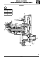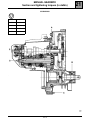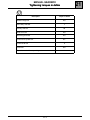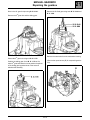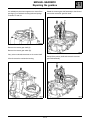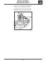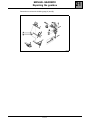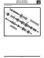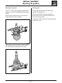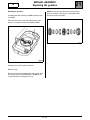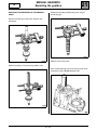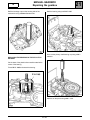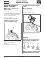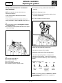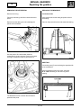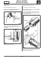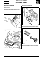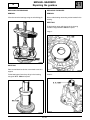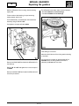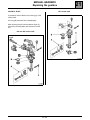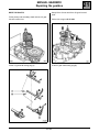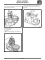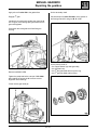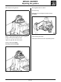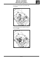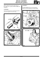
1
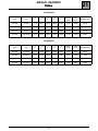
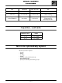
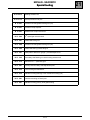
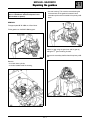
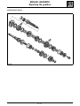
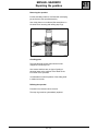
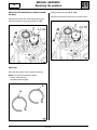
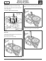
Workshop Repair Manual
Manual gearbox
Type
Range
JH1
Twingo
Clio
JH3
Clio
Laguna II
JR5
Laguna II
77 11 299 962
MARCH 2001
EDITION ANGLAISE
All copyrights reserved by Renault.
"The repair methods given by the manufacturer in this document are based on the
technical specifications current when it was prepared.
The methods may be modified as a result of changes introduced by the manufacturer
in the production of the various component units and accessories from which his
vehicles are constructed."
Copying or translating, in part or in full, of this document or use of the service part
reference numbering system is forbidden without the prior written authority of Renault.
© RENAULT 2001
Contents
Page
21 MANUAL GEARBOX
Section and tightening torques (in daNm)
Tightening torques (in daNm)
Gears
Consumables
Capacity - Lubricants
Parts to be systematically replaced
Special tooling
Repairing the gearbox
21-1
21-3
21-4
21-5
21-5
21-5
21-6
21-7
MANUAL GEARBOX
121
Section and tightening torques (in daNm)
JH GEARBOX
A
2.5
B
2.5
C
7
D
19
21-1
21
MANUAL GEARBOX
Section and tightening torques (in daNm)
JR GEARBOX
A
2.5
B
13
C
2.5
D
7
E
19
21-2
21
MANUAL GEARBOX
Tightening torques in daNm
Description
21
Torque in daNm
Gearbox edge bolt
2.5
Secondary shaft bolt
7
Primary shaft nut
19
Rear cover bolt
2.5
Reverse gear switch
2.5
Clutch slave cylinder bolt
2.1
Control shaft bolt
2
Catch bolt
0.5
Speed sensor bolt for sequential gearbox
21-3
1
MANUAL GEARBOX
Ratios
21
JH GEARBOX
Index
Type
1st
2 nd
3rd
4 th
5 th
Reverse
gear
Final
drive
Speedometer
JH1-002
Twingo
11/37
22/41
28/37
30/29
41/31
11/39
15/56
21/20
JH1-003
Twingo
11/37
22/41
28/37
30/29
39/32
11/39
15/58
21/20
JH1-007
Twingo
11/37
22/41
28/37
34/35
39/32
11/39
15/61
21/19
JH3-005
Laguna 2
11/37
22/41
28/37
34/35
39/32
11/39
14/59
None
JR GEARBOX
Index
Type
1st
2 nd
3rd
4 th
5 th
Reverse
gear
Final
drive
Speedometer
JR5-003
Laguna 2
11/37
22/41
28/37
34/35
39/32
11/39
15/61
None
JR5-008
Laguna 2
11/41
21/43
28/39
31/34
37/33
11/39
15/58
None
JR5-009
Laguna 2
11/37
22/41
28/37
34/35
39/32
11/39
15/61
None
JR5-012
Laguna 2
11/41
21/43
28/37
35/34
41/31
11/39
16/55
None
21-4
MANUAL GEARBOX
Consumables
21
Type
Packaging
Parts Stores No.
Unit
Molykote BR2
1 kg tin
77 00 421 145
Sunwheel splines
Loctite 518
24 ml syringe
77 01 421 162
Housing assembling faces
Switch threading
77 01 394 071
Fixed gear and 5th gear hub
Primary shaft nut
Secondary shaft bolt
Loctite FRENBLOC
24 cc bottle
Capacities - Lubricants
Capacity in litres
Grade
JH 2.8
TRJ 75W80W
JR 2.5
TRJ 75W80W
Parts to be systematically replaced
After they have been replaced:
– lip seals,
– O-rings,
– stop rings,
– roll pins,
– secondary shaft and differential nuts,
– gear supporting rings,
– primary and secondary shaft bearing circlips.
21-5
MANUAL GEARBOX
Special tooling
B. Vi. 22-01
Bearing extractor tool
B. Vi. 31-01
Set of punches for roll pins
B. Vi. 945
Sunwheel oil seal gasket inserting tool (JH)
B. Vi. 946
Sunwheel circlip replacer
B. Vi. 949
Selector fork roll pin rem/ref tool
B. Vi. 1000
5 th speed gear extractor shell
B. Vi. 1057
Differential locking tool
B. Vi. 1058
Sunwheel oil seal gasket inserting tool (JR)
B. Vi. 1059
Differential bearing bushes fitting kit
B. Vi. 1161
Steel plate to attach DTI gauge + pre-load adjust shims
B. Vi. 1165
Secondary shaft bearing on clutch housing extractor tool
B. Vi. 1170
Extractor for 5th speed hub gear
B. Vi. 1527
Primary and secondary shaft adjustment plate
B. Vi. 1570
Tool for fitting ball indentation
B. Vi. 1576
Mandrel for fitting bearings in the mechanism housing (JH)
B. Vi. 1581
Gearbox mounting on Desvil post
B. Vi. 1601
Mandrel for fitting primary shaft guide bearing
21-6
21
MANUAL GEARBOX
Repairing the gearbox
21
– the rear housing. This must be removed along the
horizontal axis of the gearbox because it has a
lubrication spline which is located in the primary shaft
bore.
Removing and handling the parts must be carried
out on a workbench with a knockproof cover
(thick rubber or plastic).
REMOVAL
Fit support plate B. Vi. 1581 on a Desvil shoe.
Fit the gearbox on the B. Vi. 1581 support.
19825-1
Select 1st gear using the gear lever and 5th gear by
sliding the 5th gear fork along its shaft.
Remove the secondary shaft bolt and the primary shaft
nut.
19825
Remove:
– the clutch slave cylinder,
– the bolts located inside the housing,
19824
19826
21-7
MANUAL GEARBOX
Repairing the gearbox
Drive in the 5th gear fork pin using B. Vi. 31-01.
21
Remove the 5th fixed gear using tools B. Vi. 22-01 and
B. Vi. 1000.
Remove the 5 th gear fork and the sliding gear.
19823
Remove the outer bolts from the mechanism housing.
Extract the 5 th gear hub using tool B. Vi. 1170.
(Remove the speed sensor (B) for sequential gearbox
JH1).
Position the sliding gear of tool B. Vi. 1170 as if to
select 5th gear and rotate it so as to position the splines
of the sliding gear opposite those of the hub and
withdraw the assembly.
21-8
MANUAL GEARBOX
Repairing the gearbox
21
Rotate the reverse gear shaft assembly to the left and
remove the reverse/5th gear fork shaft.
It is advisable to place two magnets or to close off the
openings (C) to retrieve the locking balls and springs
for shafts 1/2 and 3/4.
Remove the reverse gear shaft (A).
Remove the reverse gear switch (B).
Carry out an outwards stress test on the control shaft.
Gently lift the primary shaft and remove the reverse
gear shaft assembly.
Lift and remove the mechanism housing.
21-9
MANUAL GEARBOX
Repairing the gearbox
Take the pin out of the 3/4 gear fork using B. Vi. 949
and remove the shaft and 3/4 gear fork assembly.
At the same time, remove the primary and secondary
shaft assembly with the shaft and the 1/2 gear fork.
21-10
21
MANUAL GEARBOX
Repairing the gearbox
Remember to retrieve the inhibiting pegs (A) and (B).
21-11
21
MANUAL GEARBOX
Repairing the gearbox
JH SECONDARY SHAFT
21-12
21
MANUAL GEARBOX
Repairing the gearbox
Removing the sprocket
Put the secondary shaft in a vice fitted with a clamping
jaw and remove the sprocket assembly.
Use circlip pliers on one side and flat-nosed pliers on
the other when removing and refitting stop rings.
Checking parts
The sprocket teeth and the claws should not be
chipped or excessively worn.
Also ensure that there are no signs of grating or
abnormal wear on the surfaces of the shafts or the
inner walls of the sprockets.
It is advisable to mark the position of the sliding shaft
in relation to the hub.
Refitting the sprocket.
Proceed in the reverse order to removal.
The stop rings must be systematically replaced.
21-13
21
JH
MANUAL GEARBOX
Repairing the gearbox
21
Fit the bearings using tool B. Vi. 1576.
REPLACING THE BEARINGS IN THE MECHANISM
HOUSING
Knock the tool with the bearing using a small hammer.
Separate the circlips with circlip pliers and drive the
bearing inside the housing using tool B. Vi. 1576.
19821
19821
REFITTING
Place the new circlips in their respective housings.
NOTE: the circlips have different shapes:
– primary shaft circlip (A),
– secondary shaft circlip (B).
19822
21-14
JH
MANUAL GEARBOX
Repairing the gearbox
21
Remove the primary shaft bearing guide using a 38 ∅
tube.
Replacing the bearings on the clutch housing
Cut the base of the plastic hollow needle located at the
centre of the bearing.
Fit tool B. Vi. 1165 and extract the bearing.
19819
Refit the bearing guide using tool B. Vi. 1601.
REFITTING
Fit the deflector and the bearing on the press flush with
the inner side of the housing.
Set the bearing with a mortise chisel.
19818
19820
21-15
MANUAL GEARBOX
Repairing the gearbox
JR SECONDARY SHAFT
21-16
21
MANUAL GEARBOX
Repairing the gearbox
21
Removing the sprocket
Checking parts
The 2 nd, 3rd, and 4 th gear supporting rings are fitted
tightened. They will be systematically replaced during
refitting.
The sprocket teeth and the claws should not be
chipped or excessively worn.
With the press, remove the ring, hub, 3 rd gear unit
resting under the 3 rd gear claw teeth.
Also ensure that there are no signs of grating or
abnormal wear on the surfaces of the shafts or the
inner walls of the sprockets.
It is advisable to mark the position of the sliding shafts
in relation to the hub.
With the press, remove the rings, 1st and 2nd gears,
hub, sliding shaft unit resting under the 1st gear.
21-17
JR
MANUAL GEARBOX
Repairing the gearbox
Refitting the sprocket
A heating plate with a setting of 150°C should be used
for refitting.
Place the new rings on the cold heating plate. Heat
them for 15 minutes with the thermostat at 150°C.
Proceed in the reverse order to removal.
Refit the rings:
Remove a ring from the heating plate, using pliers, and
use a tube with an internal diameter of 33 mm to fit it
on the shaft until it is resting on the hub.
21-18
21
NOTE: the 1/2 gear has dual-cone synchronisation,
bring the notches of the synchro rings together with
those on the hubs and gears.
JR
MANUAL GEARBOX
Repairing the gearbox
21
Extract the secondary shaft bearing cone using an
anti-sticking pin.
REPLACING THE BEARINGS ON THE PRIMARY
SHAFT
Remove the bearings on the press using the antisticking pin.
Refit the cone on the press.
Refit the bearings on the press using a 25 ∅ tube.
Drive out the bearings cups on the housing side of the
mechanism using a 55 mm diameter tube.
19816
21-19
JR
MANUAL GEARBOX
Repairing the gearbox
21
Refit the bearing using tool B. Vi. 1167.
Refit the bearings cups on the housing side of the
mechanism using a 60 mm diameter tube.
19814
19815
Drive out the primary shaft bearing cup using a 38 ∅
extractor.
REPLACING THE BEARING ON THE JR CLUTCH
HOUSING
Cut the base of the plastic hollow needle located at the
centre of the bearing.
Fit tool B. Vi. 1165 and extract the bearing.
19813
Refit this on the press using a 46 ∅ tube.
21-20
JR
MANUAL GEARBOX
Repairing the gearbox
21
SETTING THE PRE-TENSIONING OF THE
SECONDARY SHAFT BEARINGS
A A Rotate the secondary shaft several times to fit the
bearings.
NOTE: this operation is only carried out when
replacing the bearings.
B B Set the dial gauge to zero.
Clutch housing without differential and without primary
shaft.
C C Pull the secondary shaft upwards by making a
lever out of two screwdrivers.
D D Take a reading from the dial gauge.
Fit the secondary shaft in the clutch housing with the
bearings and the pre-setting washer B. Vi. 1161, or
equivalent, of 1.60 mm (large outer ∅).
Fit the mechanism housing.
Fit and tighten to torque the box belt bolts.
Fit the dial gauge support plate B. Vi. 1161, or
equivalent, on the tripod basin mountings.
Repeat the actions (A to D) several times.
Calculate the average of the readings.
Calculation of the value of the pre-tensioning
timing washer.
Prescribed value + value of the pre-setting washer +
average of the readings on the dial gauge = value of
the pre-tensioning dial gauge washer.
Fit:
● the B. Vi. 1527 special spacer (A),
● the bolt (C),
● the dial gauge with its magnetic holder.
Example: (Values in mm).
0.26
Prescribed
value
+
0.49
Average
reading
+
1.60
Pre-setting
washer
value
=
2.35
Pretensioning
timing
washer value
NOTE: a set of timing washers of 2.15 mm to 2.43 mm
from 0.04 mm to 0.04 mm thickness is supplied as
replacement parts.
21-21
JR
MANUAL GEARBOX
Repairing the gearbox
21
SETTING THE CLEARANCE OF THE PRIMARY
SHAFT BEARINGS
A A Rotate the primary shaft several times to fit the
bearings.
NOTE: this operation is only carried out when
replacing the bearings.
B B Set the dial gauge to zero.
C C Pull the primary shaft upwards by making a lever
out of two screwdrivers.
Clutch housing without differential and without
secondary shaft.
D D Take a reading from the dial gauge.
Fit the primary shaft with the bearings and the presetting washer B. Vi. 1161 of 0.62 mm (small outer ∅).
Fit:
● the mechanism housing, fit and tighten to torque
the box belt bolts,
● the dial gauge support plate B. Vi. 1161 on the tripod
basin mountings.
Repeat the actions (A to D) several times.
Calculate the average of the readings.
Calculation of the value of the timing washer
Value of the pre-setting washer + average of the
readings on the dial gauge - 0.02 (value to subtract to
guarantee a minimum clearance) = value of the timing
washer.
Fit:
● the spacer B. Vi. 1527 (A),
● the support washer (B),
● the gear ring (C),
● the nut screwed right down (D),
● the dial gauge with its magnetic holder.
Example: (Values in mm).
0.62
Presetting
value
+
0.50
Average
reading
-
0.02
Value of recommended
minimum
clearance
=
1.10
Value of
timing
washer
NOTE: a set of timing washers of 0.86 mm to 1.30 mm
from 0.04 mm to 0.04 mm thickness is supplied as
replacement parts.
21-22
JH
MANUAL GEARBOX
Repairing the gearbox
21
REMOVING THE DIFFERENTIAL
REPLACING THE BEARINGS
Remove the O-ring.
Crownwheel side
Tap the lip seal using a drift and a small hammer to
pivot it.
Insert a small bar into the casing and place it flat on
the bearing.
Remove the seal, taking care not to damage the
splines of the sunwheel.
Press on the press with a tube and extract the bearing.
Use the press to fit a small board under the
crownwheel to act as a support. Press on the clutch
housing to release the circlip (A) and remove it.
REFITTING
The bearing race (C) must be facing the opposite side
to the crownwheel.
Drive the bearing home on the press, using tool
B. Vi. 1059 and resting on the outer ring of the
bearing.
19812
The differential comes out when the sunwheel is
pushed on the press.
21-23
JH
MANUAL GEARBOX
Repairing the gearbox
21
Sunwheel side
Refit the differential in the housing.
Remove the bearing retaining circlip (A).
Fit a wooden shim under the crownwheel.
On the press, move the bearing towards the inside of
the housing using a 50 mm diameter tube.
Fit the circlip (B) on the head (1) of tool B. Vi. 946 and
the head on the sunwheel.
Fit the tool (2) B. Vi. 946 on the head and push with
the press until the circlip falls into place in its channel.
Remove tool B. Vi. 946.
Refit the bearing using a 65 mm diameter tube. The
bearing race must be facing the opposite side to the
crownwheel.
Refit the bearing retaining circlip.
Rotate the assembly and check the rotation of the
speedometer drive gear if fitted.
21-24
JR
MANUAL GEARBOX
Repairing the gearbox
21
Remove the unit mounting nut.
REMOVING THE DIFFERENTIAL
Remove the O-ring.
Tap the lip seal using a drift and a small hammer to
pivot it.
Remove the seal, taking care not to damage the
splines of the sunwheel.
19811
Retrieve the bearing pre-tensioning setting shim (A).
Immobilise the differential unit/crownwheel assembly
using tool B. Vi. 1057 mounted on the housing.
Remove the assembly by pressing on the sunwheel.
21-25
JR
MANUAL GEARBOX
Repairing the gearbox
21
REPLACING THE BEARINGS
REPLACING THE RACES
REMOVAL
REMOVAL
Lift and remove the bearings using an anti-sticking pin.
Drive out the bearing races using a tube inserted in the
housing.
REFITTING
Fit the bearing races until they touch the housing
shoulder using tool B. Vi. 1059 and a press.
Large ∅
REFITTING
Place a small board under the crownwheel to act as a
support.
Small ∅
Fit the bearings as far as they will go in the housing
using tool B. Vi. 1059 and a press.
21-26
JR
MANUAL GEARBOX
Repairing the gearbox
21
The differential must rotate under a load of between:
– 0.5 and 2 daNm for reused bearings,
– 1.6 and 3.2 daNm for new bearings.
Refit the differential in the housing, with the bearing
lightly oiled.
Fit the sunwheel side bearing, the pre-tensioning
setting washer and the nut.
As for disassembly, immobilise the unit/crownwheel
assembly using tool B. Vi. 1057.
Pre-tighten to a torque of 1 to 2 daNm.
If the setting is not correct:
Determine the thickness of the timing washer bearing
in mind that:
19811
Remove tool B. Vi. 1057 and rotate the differential to fit
the bearings.
Refit tool B. Vi. 1057 and tighten the nut to a torque of
13 daNm.
Remove tool B. Vi. 1057 and rotate the differential and
check the pre-tension.
21-27
The pre-tension increases by approximately 0.7 to
0.8 daNm when the timing washer thickness is
reduced by 0.05 mm and vice-versa.
MANUAL GEARBOX
Repairing the gearbox
21
JH1 control shaft
CONTROL SHAFT
A prevention valve is fitted on the housing (A) of the
control shaft.
An O-ring (B) ensures that it is sealed tightly.
After removing the pin from the selector finger (C),
remove the mounting bolts and remove the control
unit.
JH3 and JR5 control shaft
21-28
MANUAL GEARBOX
Repairing the gearbox
21
Gently lift the 3/4 hub and fit the 3/4 gear fork and
shaft.
REFIT THE SHAFTS
Fit the primary and secondary shafts with the 1/2 gear
fork at the same time.
Pin the fork using tool B. Vi. 949.
19809
Fit the 5th gear shaft locking peg (B).
Fit the 1/2 gear shaft locking peg (A).
21-29
MANUAL GEARBOX
Repairing the gearbox
Fit the 5 th gear shaft (A) and the reverse gear shaft (B)
by gently lifting the primary shaft.
21
Fit the 1/2 and 3/4 locking springs and balls in the
mechanism housing and press them down using tool
B. Vi. 1570.
19817
Check the positioning of:
– the centring dowels,
– the magnet,
– the pre-tension timing washers of the bearings on
JR5.
19810
21-30
MANUAL GEARBOX
Repairing the gearbox
21
Apply a line of Loctite 518 to the gasket face.
On the secondary shaft:
Engage 3rd gear.
Put three drops of Loctite Frenbloc on the splines of
the fixed gear and fit it using tool B. Vi. 1175.
Introduce the housing while guiding the control shaft
into 3 rd gear, fit the locking spring and ball as the 5 th
gear shaft appears.
Press down the locking ball and finish fitting the
housing.
19807
19808
Remove tool B. Vi. 1570.
On the primary shaft, fit:
– the support washer (top side gear side),
– the sprocket bush,
– the 5th idle gear fitted with its synchro ring,
– the 5th gear hub fitted with its spring.
Tighten the peripheral bolt to a torque of 2.5 daNm
after rotating the primary shaft to ensure correct
alignment of the bearings.
Fit the reverse gear shaft (A).
19806
21-31
MANUAL GEARBOX
Repairing the gearbox
Refit and pin the 5 th gear fork.
21
Put the gearbox back in neutral.
Fit a new O-ring.
Fit the rear cover and tighten the bolts to torque
(2.5 daNm).
19825
19823
Fit the reverse gear switch.
Select 1 st gear using the gear lever and 5th gear by
sliding the 5 th gear fork along its shaft.
Fit the speed sensor for the JH1 sequential gearbox.
Tighten the gear bolt and nut to torque:
Primary shaft nut 2.5 daNm.
Secondary shaft bolt 16 daNm.
19824
21-32
MANUAL GEARBOX
Repairing the gearbox
21
Fit the clutch shaft seal gasket using tool B. Vi. 1601
for JR gearbox.
19805
Refit the clutch slave cylinder and tighten the bolts to a
torque of 2.1 daNm.
19826
21-33
MANUAL GEARBOX
Repairing the gearbox
Refit the differential outlet seal gasket using tool
B. Vi. 945 for the JH gearbox and B. Vi. 1058 for the
JR gearbox.
21
A
JR GEARBOX
Fit the B. Vi. 945 shield (A) on the sunwheel and
position the oiled seal gasket with tool B. Vi. 1058.
JH GEARBOX
Fit the oiled shield (A) on the sunwheel and position
the oiled seal gasket (C) with the tool (B).
21-34