1
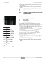
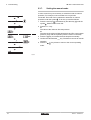
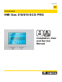
Great Britain EN Control panel HMI Gas 310/610 ECO PRO Installation, User and Service Manual 125482-04 Contents 1 Introduction ................................................................................................4 1.1 Symbols used .......................................................4 1.2 Abbreviations ........................................................4 1.3 Liabilities ...............................................................4 1.3.1 1.3.2 1.3.3 2 3 Safety instructions and recommendations ..............................................6 2.1 Safety instructions ...............................................6 2.2 Recommendations ................................................6 Technical description ................................................................................7 3.1 Control panel .........................................................7 3.1.1 3.1.2 4 Control panel assembly .......................................9 Commissioning ........................................................................................10 5.1 Switch on the instrument panel ........................10 5.2 Reading out measured values ...........................11 5.2.1 5.2.2 5.2.3 5.3 Reading the various current values .......................11 Readout from the hour counter and percentage of successful starts ....................................................12 Status and sub-status ...........................................12 Changing the settings ........................................13 5.3.1 5.3.2 5.3.3 5.3.4 5.3.5 5.3.6 5.3.7 1 Functions of the keys ..............................................7 Meaning of the symbols on the display ...................8 Installation ..................................................................................................9 4.1 5 Manufacturer’s liability .............................................4 Installer’s liability .....................................................5 User’s liability ..........................................................5 Parameter descriptions .........................................13 Modification of the user-level parameters .............18 Modification of the installer-level parameters ........18 Setting the maximum heat input for central heating operation ...............................................................19 Return to the factory settings ................................20 Carrying out an auto-detect ...................................20 Setting the manual mode ......................................21 160514 - 125482-04 Contents 6 Troubleshooting .......................................................................................22 6.1 Shutdowns and lock-outs ..................................22 6.1.1 6.1.2 6.1.3 6.2 Error memory ......................................................27 6.2.1 6.2.2 2 General .................................................................22 Blocking .................................................................22 Lock out .................................................................24 Error readout memorised ......................................28 Deletion of the error display ..................................29 160514 - 125482-04 3 160514 - 125482-04 1. Introduction HMI Gas 310/610 ECO PRO 1 Introduction 1.1 Symbols used In these instructions, various danger levels are employed to draw the user’s attention to particular information. In so doing, we wish to safeguard the user’s safety, obviate hazards and guarantee correct operation of the appliance. DANGER Risk of a dangerous situation causing serious physical injury. WARNING Risk of a dangerous situation causing slight physical injury. CAUTION Risk of material damage. Signals important information. ¼Signals a referral to other instructions or other pages in the instructions. 1.2 Abbreviations 4 PCU: Primary Control Unit - PCB for managing burner operation 4 PSU: Parameter Storage Unit - Parameter storage for PCBs PCU and SU 4 SCU: Secondary Control Unit - Extended control PCB 4 SU: Safety Unit - Safety PCB 4 Central heating: Central heating 1.3 Liabilities 1.3.1. Manufacturer’s liability Our products are manufactured in compliance with the requirements of the various applicable European Directives. They are therefore delivered with [ marking and all relevant documentation. 160514 - 125482-04 4 HMI Gas 310/610 ECO PRO 1. Introduction In the interest of customers, we are continuously endeavouring to make improvements in product quality. All the specifications stated in this document are therefore subject to change without notice. Our liability as the manufacturer may not be invoked in the following cases: 4 Failure to abide by the instructions on using the appliance. 4 Faulty or insufficient maintenance of the appliance. 4 Failure to abide by the instructions on installing the appliance. 1.3.2. Installer’s liability The installer is responsible for the installation and inital start up of the appliance. The installer must respect the following instructions: 4 Read and follow the instructions given in the manuals provided with the appliance. 4 Carry out installation in compliance with the prevailing legislation and standards. 4 Perform the initial start up and carry out any checks necessary. 4 Explain the installation to the user. 4 If a maintenance is necessary, warn the user of the obligation to check the appliance and maintain it in good working order. 4 Give all the instruction manuals to the user. 1.3.3. User’s liability To guarantee optimum operation of the appliance, the user must respect the following instructions: 4 Read and follow the instructions given in the manuals provided with the appliance. 4 Call on qualified professionals to carry out installation and initial start up. 4 Get your installer to explain your installation to you. 4 Have the required checks and services done by a qualified professional. 4 Keep the instruction manuals in good condition close to the appliance. This appliance is not intended to be used by persons (including children) whose physcial, sensory or mental capacity is impaired or persons with no experience or knowledge, unless they have the benefit, through the intermediary of a person responsible for their safety, of supervision or prior instructions regarding use of the appliance. Care should be taken to ensure that children do not play with the appliance. If the mains lead is damaged it must be replaced by the original manufacturer, the manufacturer’s dealer or another suitably skilled person to prevent hazardous situations. 5 160514 - 125482-04 HMI Gas 310/610 ECO PRO 2. Safety instructions and recommendations 2 Safety instructions and recommendations 2.1 Safety instructions Strictly follow the safety instructions given. WARNING 4 This equipment operates using electricity. 4 Disconnect the equipment from the power supply before making electrical connections. Only qualified professionals are authorised to work on the appliance and the installation. Only the manufacturer is authorised to carry out repairs. 4 4 2.2 Recommendations Only qualified professionals are authorised to work on the appliance and the installation. 4 4 4 160514 - 125482-04 Store this document in the document wallet on the inside of the boiler casing. Keep the appliance accessible at all times. Never remove or cover labels and rating plates affixed to the appliance. 6 HMI Gas 310/610 ECO PRO 3. Technical description 3 Technical description 3.1 Control panel For operation of the boiler Gas 610 ECO PRO: Each module has its own instrument panel. 3.1.1. 1 St 8 ºCºFh barPsi rpm kWµA ºC ± 30l/min 2 3 6 4 5 9 7 T003479-D Functions of the keys 1 Display 2 > [Escape] or J key 3 D Heating temperature key or [-] 4 [+] key 5 S [Enter] or cancel d Key lock-out 6 B [Chimney-sweeping] keys (press the 2 and 3 keys simultaneously) 7 f [Menu] keys (press the 4 and 5 keys simultaneously) 8 On/Off switch 9 PC connection The display has several positions and symbols and provides information on the operating condition of the boiler and any possible failures. A service message may also appear in the display. Numbers, dots and/or letters may be displayed. The symbols located above the function keys indicate their current function. 4 The display content can be changed using parameter p4. 4 The brightness of the display lighting can be changed using parameter p5. Key lock-out is activated by setting parameter p4 to 3. If no key is pressed for 3 minutes, the display lighting switches off and only the current water pressure, the J key and the d symbol are displayed (Water pressure: Only with the hydraulic pressure sensor connected). Press the S key for about 2 seconds to reactivate the display and other keys. The d symbol disappears from the display. 7 160514 - 125482-04 HMI Gas 310/610 ECO PRO 3. Technical description 3.1.2. Meaning of the symbols on the display / On/Off switch (0/1): After 5 lock-outs, the boiler must be switched off/on again. Chimney-sweeping position: B Forced full or part load for CO measurement. 2 b Circulation pump: The pump operates. User menu: Parameters at user level can be changed. D Central heating function: Access to central heating temperature parameter. Heating programme deactivated: The heating function is deactivated. d Locking the keys: Key lock-out is activated. Q W C E ? Information menu: Reading the various current values. Manual mode: Boiler is set to manual operation. Service menu: Parameters at installer level can be changed. Defect: c Boiler indicates a fault. This can be seen from the e code and red display. I Burner level: Output level . Outside sensor: Z (Only if an outside temperature sensor is connected = Accessory). g K e Yellow display with the symbols: $ + K + Z (Maintenance message). Water pressure: The water pressure is too low. (Only with the hydraulic pressure sensor connected) ] Antifreeze protection: Boiler is running in frost protection mode. \ Hour counter menu: Readout of the operating hours, number of successful starts and hours on mains supply. [ Signal strength symbol: Signal strength of the wireless controller (if connected). Battery symbol: Status of battery of wireless controller (if connected). 160514 - 125482-04 8 4. Installation 4 Installation 4.1 Control panel assembly HMI Gas 310/610 ECO PRO The instrument panel HMI GAS 310/610 ECO PRO is standard fitted in the Gas 310/610 ECO PRO boiler. 9 160514 - 125482-04 5. Commissioning HMI Gas 310/610 ECO PRO 5 Commissioning 5.1 Switch on the instrument panel For operation of the boiler Gas 610 ECO PRO: The features and instructions described are for each boiler module. The instrument panel HMI GAS 310/610 ECO PRO is ready for use, as soon as the power to the boiler is switched on. 1. Open the gas valve on the boiler. 2. Turn on the boiler using the on/off switch. 3. Set the controls (thermostats, control system) so that they request heat. 4. The start-up cycle begins and cannot be interrupted. During the start-up cycle, the display shows the following information: A short test where all segments of the display are visible. fK[xx: Software version pK[xx: Parameter version The version numbers are displayed alternately. By pressing the S key for a short time, the current operating status is shown on the display: Heat demand Heat demand stopped 1: Fan ON 5: Burner stop ": Boiler is igniting 6: Post-circulation of the pump 3: Heating System 0: Standby In STAND-BY, the display normally shows the water pressure next to 0 (only when the hydraulic pressure sensor is connected) and the symbols D and H. Error during the start-up procedure: 4 No information is shown on the display: - Check the mains supply voltage - Check the main fuses - Check the connection of the mains lead to the connector in the instrument box (Check the fuse F2 = 10 AT) - Check the fuses on the control panel: (F1 = 2 AT) 4 A fault is indicated on the display by the fault symbol c and a flashing fault code. - The meaning of the error codes is given in the error table. - Press for 2 seconds on key J to restart the boiler. 160514 - 125482-04 10 HMI Gas 310/610 ECO PRO 5. Commissioning 5.2 Reading out measured values For operation of the boiler Gas 610 ECO PRO: The features and instructions described are for each boiler module. 5.2.1. Reading the various current values The following current values can be read off the information menu Q: 4 5t = State. 4 5v = Sub-status. 4 t1 = Flow temperature (°C). 4 t" = Return temperature (°C). 4 t4 = Outside temperature (°C) Only with an outside temperature sensor (Accessory). 4 t6 = Exchanger temperature (°C). 4 5p = Internal set point (°C). 4 fl = Ionization current (µA). 4x 4 Mf = Fan speed (rpm). 4 pr = Water pressure (bar (MPa)). Only with the hydraulic pressure sensor connected (Accessory). 4 p; = Supplied relative heat output (%). 4 51 = Pressure switch minimum Gps (Kz = Not connected / K1 = Gas pressure OK / K" = Gas pressure incorrect) Only with connected minimum gas pressure switch (Accessory) 4 5" = Gas valve leak proving system Vps (Kz = Not connected / K1 = No gas leak / K" = Gas leak present) Only with connected gas leakage control (Accessory). 4 V1 = Analogue input (V). 4 V" = Analogue output (V). The current values can be read as follows: 1. Press the two f keys simultaneously. The symbol Q flashes. 2. Confirm using key S. 5t is displayed, alternating with the current status 3 (for example). 3. Press the [+] key. 5v is displayed, alternating with the current sub-status 30 (for example). 4. Press the [+] key. t1 is displayed, alternating with the current flow temperature 60°C (for example). 5. Press the [+] key successively to scroll down the various parameters 6. Press the [+] key. The readout cycle starts again with 5t. 2x T004355-A 11 7. Press the > key 2 times to return to the current operating mode. 160514 - 125482-04 HMI Gas 310/610 ECO PRO 5. Commissioning 5.2.2. Readout from the hour counter and percentage of successful starts 1. Press the two keys f simultaneously and then key [+] until the symbol \ flashes on the menu bar. 2. Press the S key. hr and the number of hours of boiler operation 3600 (for example) are displayed alternately. 5x 3. Press the [+] key. The display shows D. hr is displayed, alternating with the number of operating hours in central heating operation 560 (for example). 4. Press the [+] key. The display shows @. 5Z is displayed, alternating with the percentage of successful starts 92 % (for example). 5. Press the > key 2 times to return to the current operating mode. 2x T000816-G 5.2.3. Status and sub-status The information menu Q gives the following status and sub-status numbers: State 5t 0 Rest 1 Boiler start (Heat demand) Sub-status 5v 0 Rest 1 Anti-hunting 2 Open hydraulic valve 3 Start pump 4 Wait for the correct temperatures for burner start 10 Open external gas valve 11 Fan ON 12 Open flue gas damper 13 Pre-ventilation 14 Wait for release signal 2 Burner start 15 Burner on 16 Gas valve leak proving system VPS 17 Pre-ignition 18 Main ignition 19 Flame detection "0 Intermediate ventilation 160514 - 125482-04 12 5. Commissioning State 5t HMI Gas 310/610 ECO PRO Sub-status 5v 30 Temperature control 31 Limited temperature control (ΔT safety) 32 Output control 33 Increase protection level 1 (Modulate down) 3 Burner for central heating operation 34 Increase protection level 2 (Part load) 35 Increase protection level 3 (Blockage) 36 Modulate up for flame control 37 Temperature stabilisation time 38 Cold start 40 Burner off 41 Post ventilation 42 Fan OFF 43 Close flue gas damper 5 Burner stop 44 Stop fan 45 Close external gas valve 6 Boiler stop (End of heat demand) 62 Close hydraulic valve 63 Start anti-hunting 0 Wait for burner start 1 Anti-hunting 8 Control stop xx Shutdown code xx 9 Blocking 5.3 60 Pump post circulation 61 Pump off Changing the settings The boiler control panel is set for the most common heating systems. With these settings, practically all heating systems operate correctly. The user or installer can optimise the parameters according to own preferences. For the settings of the Gas 610 ECO PRO boiler: The parameters and settings described are for each boiler module. Each parameter changing must therefore be done identical on each module. 5.3.1. Parameter descriptions n Boiler type Gas 310 ECO PRO Factory setting Parameter Description Adjustment range Gas 310 ECO PRO 285 355 430 500 575 650 Flow temperature: TSET 20 to 90 °C 80 p2 Post-circulation of the pump 1 to 98 minutes 99 minutes = continuous 5 p3 Boiler regulation 0 = Heating deactivated 1 = Heating activated 1 p1 13 160514 - 125482-04 HMI Gas 310/610 ECO PRO 5. Commissioning Factory setting Parameter Description Adjustment range Gas 310 ECO PRO 285 355 430 500 575 650 p4 Display screen 0 = Simple 1 = Comprehensive 2 = Automatic switching to simple after 3 minutes 3 = Automatic switching to simple after 3 minutes; Key blocking is active p5 Brightness of display lighting 0 = Dimmed 1 = Bright p17 Maximum fan speed G20 (Gas H) (x100 rpm) 52 55 35 38 43 41 p18 Minimum fan speed G20 (Gas H) (x100 rpm) 14 15 9 10 11 10 p19 offset Minimum fan speed Do not modify (x1 rpm) 0 50 50 50 0 50 p20 Start speed Do not modify (x100 rpm) 25 25 13 14 14 14 p21 Maximum flow temperature of 0 to 90 °C system 90 p22 Heat curve set point (Maximum outside temperature) Only with an outside temperature sensor (Accessory) 0 to 30 °C 20 p23 Heat curve set point (Flow temperature) Only with an outside temperature sensor (Accessory) 0 to 90 °C 20 p24 Heat curve set point (Minimum outside temperature) Only with an outside temperature sensor (Accessory) -30 to 0 °C -15 p25 Antifreeze temperature Only with an outside temperature sensor (Accessory) from - 30 to 0°C - 10 p26 Fault relay function X4 (If connected) 0 = Operation signal 1 = Alarm signal 0 p27 Fault relay function X5 (If connected) 0 = Operation signal 1 = Alarm signal 1 p28 Minimum water pressure Wps Only with the hydraulic 0 - 7 bar (MPa) (x 0.1bar (MPa)) pressure sensor connected 0 = Not connected (Accessory) 0 p29 Minimum gas pressure check 0 = Not connected Gps 1 = Connected (Accessory) 0 p30 Hydraulic valve running time HdV (If connected) 0 to 255 seconds 0 p31 Flue gas damper running time FgV If connected 0 to 255 seconds 0 p32 Release waiting time 0 to 255 seconds 0 160514 - 125482-04 2 1 14 5. Commissioning HMI Gas 310/610 ECO PRO Factory setting Parameter Description Adjustment range Gas 310 ECO PRO 285 355 430 500 575 650 p33 Gas valve leak proving system VPS (Accessory) 0 = Not connected 1 = Connected 0 p34 Mains detection phase 0 = Off 1 = On 1 p35 Shutdown input function 1 = Shutdown without frost-protection 2 = Shutdown with frost protection 3 = Lock-out with frost protection (Pump only) 1 p36 From Analogue output (0 10V) SCU-S05 control PCB 0 = 0-10 V Wilo control PCB 1 = 0-10 V Grundfos control PCB 2 = PWM pump 3 = Heat output feedback 4 = Temperature feedback 0 p37 0 = OpenTherm regulator From Analogue input (0-10V) 1 = Analogue temperature-based control (°C) SCU-S05 control PCB 2 = Analogue heat output-based control (%) 1 p38 Average flow temperature factor 6 p39 Display units 0 = °C / bar 1 = F / PSI 0 p40 Maintenance message 0 = Service messages off 1 = Service messages on 2 = Customized service message 0 p41 Service operating hours ( x 100) Do not modify 175 p42 Service burning hours ( x 100) Do not modify 30 p43 Setting the pump speed (Minimum pump speed for central heating operation) 2 - 10 (x 10%) 2 p44 Setting the pump speed (Maximum pump speed for central heating operation) 6 - 10 (x 10%) 10 p45 ΔT Modulate down 10 to 30 °C 25 Zd 0 = No detection Detection of connected SCUs 1 = Detection df and dV Factory setting 15 Do not modify To restore the factory settings or when replacing the main PCB, enter the values dF and dU from the type plate in parameters df and dV 0 X Y 160514 - 125482-04 HMI Gas 310/610 ECO PRO 5. Commissioning n Boiler type Gas 610 ECO PRO Factory setting Parameter Description Adjustment range Gas 610 ECO PRO 570 710 860 1000 1150 1300 p1 Flow temperature: TSET p2 1 to 98 minutes Post-circulation of the pump 99 minutes = continuous p3 Boiler regulation 0 = Heating deactivated 1 = Heating activated 1 p4 Display screen 0 = Simple 1 = Comprehensive 2 = Automatic switching to simple after 3 minutes 3 = Automatic switching to simple after 3 minutes; Key blocking is active 2 p5 Brightness of display lighting 0 = Dimmed 1 = Bright 1 p17 Maximum fan speed G20 (Gas H) (x100 rpm) 52 55 35 38 43 41 p18 Minimum fan speed G20 (Gas H) (x100 rpm) 19 18 13 12 14 13 p19 offset Minimum fan speed Do not modify (x1 rpm) 0 50 0 50 0 50 p20 Start speed Do not modify (x100 rpm) 25 25 14 14 15 16 p21 Maximum flow temperature of system 0 to 90 °C 90 p22 Heat curve set point (Maximum outside temperature) Only with an outside temperature sensor (Accessory) 0 to 30 °C 20 p23 Heat curve set point (Flow temperature) Only with an outside temperature sensor (Accessory) 0 to 90 °C 20 p24 Heat curve set point (Minimum outside temperature) Only with an outside temperature sensor (Accessory) -30 to 0 °C -15 p25 Antifreeze temperature Only with an outside temperature sensor (Accessory) from - 30 to 0°C - 10 p26 Fault relay function X4 (If connected) 0 = Operation signal 1 = Alarm signal 0 p27 Fault relay function X5 (If connected) 0 = Operation signal 1 = Alarm signal 1 p28 Minimum water pressure Wps Only with the hydraulic pressure sensor connected (Accessory) 0 - 7 bar (MPa) (x 0.1bar (MPa)) 0 = Not connected 0 160514 - 125482-04 20 to 90 °C 80 5 16 5. Commissioning HMI Gas 310/610 ECO PRO Factory setting Parameter Description Adjustment range Gas 610 ECO PRO 570 710 860 1000 1150 1300 p29 Minimum gas pressure check Gps (Accessory) 0 = Not connected 1 = Connected 0 p30 Hydraulic valve running time HdV (If connected) 0 to 255 seconds 0 p31 Flue gas damper running time FgV If connected 0 to 255 seconds 0 p32 Release waiting time 0 to 255 seconds 0 p33 Gas valve leak proving system VPS (Accessory) 0 = Not connected 1 = Connected 0 p34 Mains detection phase 0 = Off 1 = On 1 p35 Shutdown input function 1 = Shutdown without frost-protection 2 = Shutdown with frost protection 3 = Lock-out with frost protection (Pump only) 1 p36 From Analogue output (0 10V) SCU-S05 control PCB 0 = 0-10 V Wilo control PCB 1 = 0-10 V Grundfos control PCB 2 = PWM pump 3 = Heat output feedback 4 = Temperature feedback 0 p37 From Analogue input (0-10V) SCU-S05 control PCB 0 = OpenTherm regulator 1 = Analogue temperature-based control (°C) 2 = Analogue heat output-based control (%) 1 p38 Average flow temperature factor p39 Display units 0 = °C / bar 1 = F / PSI 0 p40 Maintenance message 0 = Service messages off 1 = Service messages on 2 = Customized service message 0 p41 Service operating hours ( x 100) Do not modify 175 p42 Service burning hours ( x 100) Do not modify 30 p43 Setting the pump speed (Minimum pump speed for central heating operation) 2 - 10 (x 10%) 2 p44 Setting the pump speed (Maximum pump speed for central heating operation) 6 - 10 (x 10%) 10 p45 ΔT Modulate down 10 to 30 °C 25 Detection of connected SCUs 0 = No detection 1 = Detection 0 Zd df and dV Factory setting 17 Do not modify To restore the factory settings or when replacing the main PCB, enter the values dF and dU from the type plate in parameters df and dV 6 X Y 160514 - 125482-04 5. Commissioning HMI Gas 310/610 ECO PRO 5.3.2. Modification of the user-level parameters Parameters p1 to p5 can be changed by the user. CAUTION 1x Modification of the factory settings may be detrimental to the functioning of the appliance. 1. Press the two keys f simultaneously and then key [+] until the symbol W flashes on the menu bar. 2. Select the users menu using the key S. p[1 is displayed with 1 flashing. 3. Press the S key a second time. The value 80°C appears and 2x T001906-B flashes (for example). 4. Change the value by pressing the [-] or [+] key. In this example using key [-] to 60°C. 5. Confirm the value with the S key. p[1 is displayed with 1 flashing. 6. Press the > key 2 times to return to the current operating mode. The parameters p2 to p5 are changed in the same way as p1. After step 2, use the [+] key to move to the required parameter. 5.3.3. Modification of the installer-level parameters Parameters p17 to df must only be modified by a qualified professional. To prevent unwanted settings, some parameter settings can only be changed after the special access code 0012 is entered. 3x CAUTION Modification of the factory settings may be detrimental to the functioning of the appliance. 1. Press the two keys f simultaneously and then key [+] until the symbol ? flashes on the menu bar. 2. Select the fitter menu using the key. c0de appears on the display. 3. Use keys [-] or [+] to input the installer code 0012. 4. Confirm using key S. p[1 is displayed with 1 flashing. 5. Press the S key a second time. The value 80°C appears and flashes (for example). 6. Change the value by pressing the [-] or [+] key. In this example using key [-] to 60°C. 2x T000819-E 160514 - 125482-04 7. Confirm the value with the S key: p[1 is displayed with 1 flashing. 18 5. Commissioning HMI Gas 310/610 ECO PRO 8. If necessary, set other parameters by selecting them using the [-] or [+] keys. 9. Press the > key 2 times to return to the current operating mode. The boiler also returns to operating status if no keys are pressed for 3 minutes. 5.3.4. Setting the maximum heat input for central heating operation Type Gas 310- ECO PRO 575 700 M 539 500 F Q M Maximum heat input (natural gas) F Factory setting Q Power input (kW) R Fan rotation speed (rpm) 400 300 200 109 0 1100 2000 4300 3000 R 5000 R000279 The speed can be changed using parameter p17. A linear relationship exists between the speed and the input: See graph. A graph for the other boilers can be produced in the same way. 1. Press the two keys f simultaneously and then key [+] until the symbol ? flashes on the menu bar. 2. Select the installers menu using the key S. c0de appears 3x on the display. 3. Use keys [-] or [+] to input the installer code 0012. 4. Confirm using key S. p[1 is displayed with 1 flashing. 5. Press the [+] key to go to parameter p[17. 6. Confirm using key S. 7. Press the [+] button to reduce the speed from 54 to 50, for example. 8. Confirm the value with the S key. ...x 9. Press the > key 2 times to return to the current operating mode. ...x 2x T004356-A 19 160514 - 125482-04 5. Commissioning HMI Gas 310/610 ECO PRO 5.3.5. Return to the factory settings CAUTION By restoring the factory settings, customized settings can also be erased. So first write down all the customized parameters (eg settings for attached accessories such as a flue gas valve or gas leak control). Adjust these specific settings again after the factory settings have been restored. 1. Press the two keys f simultaneously and then key [+] until the symbol ? flashes on the menu bar. 2. Select the installers menu using the key S. c0de appears 3x on the display. 3. Use keys [-] or [+] to input the installer code 0012. 4. Confirm using key S. p[1 is displayed with 1 flashing. 5. Press the [+] key several times. p[df is displayed with df flashing. 6. Press the S key. df[x is displayed with x flashing. This is the current value of X for dF. Check this against the value of X on the type plate. 7. Enter the value of X shown on the type plate using the [-] or [+] key. 8. Confirm the value with the S key, df[y is displayed with y ...x flashing. This is the current value of Y for dU. Check this against the value of Y on the type plate. 9. Enter the value of Y shown on the type plate using the [-] or [+] key. 10.Confirm the value with the S key. The factory settings are reset. 11.The display returns to the current operating mode. T000820-H 5.3.6. Carrying out an auto-detect After removing a control PCB, an auto-detect must be carried out. To do this, proceed as follows: 1. Press the two keys f simultaneously and then key [+] until the symbol ? flashes on the menu bar. 3x 2. Select the installers menu using the key S. c0de appears on the display. 3. Use keys [-] or [+] to input the installer code 0012. 4. Confirm using key S. p[1 is displayed with 1 flashing. 5. Press the [+] key several times. p[Zd is displayed with Zd flashing. 6. Confirm using key S. Auto-detect is carried out. ...x 7. The display returns to the current operating mode. T000445-B 160514 - 125482-04 20 5. Commissioning HMI Gas 310/610 ECO PRO 5.3.7. Setting the manual mode In some cases it may be necessary to switch the boiler to manual operation, For example, if the controller has not yet been connected. The boiler can be switched to automatic or manual operation under the symbol E. To do this, proceed as follows: 1. Press the two keys f simultaneously and then key [+] until the symbol E flashes on the menu bar. 2x 2. Press the S key: or The value of the minimum flow temperature. or The value of the minimum flow temperature and The current water pressure (Only with the hydraulic pressure sensor connected). 3. Press the [+] key to increase the flow temperture manually. 4. Confirm the value with the S key. The boiler is now set to manual operation. 5. Press the > key 2 times to return to the current operating mode. bar 2x T005266-B 21 160514 - 125482-04 HMI Gas 310/610 ECO PRO 6. Troubleshooting 6 Troubleshooting 6.1 Shutdowns and lock-outs For operation of the boiler Gas 610 ECO PRO: The features and instructions described are for each boiler module. 6.1.1. General The boiler is fitted with an electronic regulation and control unit. The heart of the control system is a microprocessor, the Comfort Master©, which controls the boiler and also protects the boiler. When a failure is signalled, the boiler stops or becomes locked. 6.1.2. Blocking A (temporary) blocking mode is a boiler operating function caused by an unusual situation. In this case, the display gives a code of blocking (code 5t[9). The boiler control will try to re-start several times. The boiler will start up again after the blocking conditions have been eliminated. The shutdown codes can be read out as follows: 1. Press the two f keys simultaneously. 2. Confirm by pressing key S. 5t is displayed, alternating with the shutdown code 9. 3. Press the [+] key. 5v appears on the display. The boiler starts up again automatically when the reason for the blocking has been removed. T001632-B Shutdown code Description 5v[0 Parameter error 4 5v[1 Maximum flow temperature exceeded 4 Maximum heat exchanger temperature increase has been exceeded 4 5v[3 Probable causes 4 Parameter error on the PSU PCB Non-existent or insufficient circulation Checking / solution 4 Reset df and dV 4 4 Restore parameters with Recom Check the circulation (direction, pump, valves) Reasons for the heat demand Check the circulation (direction, pump, valves) Check the water pressure 4 4 4 Non-existent or insufficient 4 circulation Sensor error 4 4 (1) These lock-outs are not stored in the fault memory 160514 - 125482-04 Check the cleanliness of the heat exchanger Check that the sensors are operating correctly Check that the sensor has been correctly fitted 22 6. Troubleshooting Shutdown code 5v[4 Description The maximum temperature increase speed tolerated in the exchanger has been exceeded HMI Gas 310/610 ECO PRO Probable causes 4 Non-existent or insufficient circulation Checking / solution 4 4 4 5v[5 5v[6 4 Maximum difference between the flow and return temperature exceeded 4 4 Non-existent or insufficient 4 circulation Sensor error 4 No release signal 4 External cause 4 4 Parameter error 4 Check the parameters 4 4 4 Check the wiring 4 Invert phase and neutral 4 Set parameter p34 to 0 4 Bad connection Mains supply incorrectly wired Floating or 2 phase network External cause 4 Suppress the external cause 4 Parameter error 4 Check the parameters 4 4 Bad connection External cause 4 4 Check the wiring Suppress the external cause 4 Parameter error 4 Check the parameters 4 4 4 Check the wiring Bad connection Bad connection with BUS 4 Check the wiring SCU PCB not installed in 4 Carry out automatic detection the boiler The water pressure is too Check: low 4 Water pressure in the installation Incorrect adjustment of water pressure parameter 4 Setting of hydraulic pressure sensor 28 4 Setting parameter 28 Water leakage 4 Check that the gas valve is fully opened Non-existent or insufficient 4 Check the supply pressure circulation 4 Check whether the Gps gas pressure Incorrect setting of the control system has been correctly fitted Gps gas pressure switch 4 Replace the Gps gas pressure control on the SCU PCB system if need be Wrong SU PCB for this 4 Replace the SU PCB boiler 5v[9 Phase and neutral of mains supply mixed up 4 5v[10 Shutdown input is open 5v[11 5v[13 Shutdown input active or frost protection active Communication error with the SCU PCB 4 4 5v[14 The water pressure is too low Check the circulation (direction, pump, valves) Check the water pressure Check the cleanliness of the heat exchanger Check that the sensors are operating correctly Check that the sensor has been correctly fitted Suppress the external cause 4 5v[8 Check the circulation (direction, pump, valves) Reasons for the heat demand 4 4 4 5v[15 Gas pressure too low 4 5v[16(1) Configuration fault or SU PCB not recognised 4 5v[17(1) Configuration fault or default 4 parameter table incorrect Parameter error on the PCU PCB 4 Replace the PCU PCB 5v[18(1) Configuration fault or PSU PCB not recognised 4 Wrong PCU PCB for this 4 boiler Replace the PCU PCB 5v[19(1) Configuration fault or parameters df-dV unknown 4 Parameter error Reset df and dV 5v[20(1) Configuration procedure active 4 5v[21 Communication error with the SU PCB 4 Active for a short time after 4 switching on the boiler 4 Bad connection (1) These lock-outs are not stored in the fault memory 23 4 No action required Check whether the SU PCB has been correctly fitted in the connector on PCU PCB 160514 - 125482-04 HMI Gas 310/610 ECO PRO Shutdown code 5v[22 6. Troubleshooting Description Probable causes No flame during operation 4 Checking / solution No ionization current 4 Purge the gas supply to remove air 4 Check that the gas valve is fully opened 4 Check the supply pressure 4 Check the operation and setting of the gas valve unit Check that the air inlet and flue gas discharge flues are not blocked Check that there is no recirculation of flue gases 4 4 5v[24 Gas leakage control fault 4 Bad connection 4 Gas valve unit defect 4 5v[25 Internal error on the SU PCB 4 4 Gas leakage control VPS 4 faulty 4 Check the wiring Replace the gas valve unit Replace gas leakage control VPS Replace the SU PCB (1) These lock-outs are not stored in the fault memory 6.1.3. Lock out If the blocking conditions still exist after several start up attempts, the boiler will switch into locking mode (fault). The display shows : In a red flashing display: 4 The symbol c 4 The symbol J 4 The fault code (for example e[01) 4 Press the J key for 2 seconds. If the error code continues to display, search for the cause in the error table and apply the solution. The error code is important for rapid and correct tracking of the type of problem and for any technical assistance from Remeha. Error code Description e[00 Storage unit PSU parameter not found e[01 The safety parameters are incorrect e[02 e[03 Probable causes 4 Bad connection 4 Check the wiring 4 Bad connection 4 Check the wiring 4 PSU defective 4 Bad connection 4 4 Replace PSU Check the wiring 4 Check that the sensors are operating correctly 4 Check that the sensor has been correctly fitted 4 4 Replace the sensor if necessary Check the wiring 4 Check that the sensors are operating correctly 4 Check that the sensor has been correctly fitted 4 Replace the sensor if necessary Flow temperature sensor 4 short circuited 4 Sensor not or badly connected Sensor fault 4 Bad connection Flow temperature sensor 4 open circuit 4 160514 - 125482-04 Checking / solution Sensor not or badly connected Sensor fault 24 6. Troubleshooting Error code Description HMI Gas 310/610 ECO PRO Probable causes 4 e[04 e[05 e[06 e[07 4 4 Temperature of heat 4 exchanger too low 4 Exchanger temperature too high 4 Return temperature sensor short circuited Return temperature sensor open circuit e[08 e[09 e[10 e[11 4 4 e[12 25 4 Sensor not or badly connected Sensor fault Check the wiring 4 Vent the air in the heating system 4 Check the circulation (direction, pump, valves) 4 Check the water pressure 4 Check the cleanliness of the heat exchanger 4 Check that the sensor has been correctly fitted 4 Check that the sensors are operating correctly 4 4 Replace the sensor if necessary Check the wiring 4 Check that the sensor has been correctly fitted 4 Check that the sensors are operating correctly 4 4 Replace the sensor if necessary Check the wiring Bad connection 4 4 Sensor not or badly connected Sensor fault 4 Bad connection 4 Sensor not or badly connected Sensor fault 4 Check that the sensor has been correctly fitted 4 Check that the sensors are operating correctly 4 4 Replace the sensor if necessary Check the wiring Bad connection 4 Check the cleanliness of the heat exchanger No circulation 4 Vent the air in the heating system Sensor not or badly connected Sensor fault 4 Check the circulation (direction, pump, valves) 4 Check the water pressure 4 Check that the sensors are operating correctly 4 4 Check that the sensor has been correctly fitted Vent the air in the heating system 4 Check the water pressure Check that the heating pump is operating correctly 4 Return temperature 4 too low 4 Return temperature too high 4 Difference between the flow and return temperatures too great No circulation 4 4 4 4 Bad connection Checking / solution 4 No circulation 4 4 Sensor not or badly connected Sensor fault 4 Check the circulation (direction, pump, valves) 4 Check the cleanliness of the heat exchanger 4 Check that the sensor has been correctly fitted 4 Check that the sensors are operating correctly 4 4 4 Replace the sensor if necessary Check that the air inlet and flue gas discharge flues are not blocked Check the wiring 4 Check the water pressure 4 Check that the heating pump is operating correctly 4 Check the circulation (direction, pump, valves) 4 Check the cleanliness of the heat exchanger 4 Check that the sensor has been correctly fitted 4 Check that the sensors are operating correctly 4 Replace the sensor if necessary 4 4 Air differential pressure switch has 4 been triggered Temperature of heat 4 exchanger above 4 normal range (highlimit thermostat STB) 4 Air inlet or flue gas discharge blocked Bad connection No circulation Sensor not or badly connected Sensor fault 160514 - 125482-04 HMI Gas 310/610 ECO PRO Error code Description 6. Troubleshooting Probable causes 4 No ignition Checking / solution 4 Check cabling of ignition transformer 4 Check the ionization/ignition electrode 4 Check breakdown to earth 4 Check the earthing 4 4 Defective control SU PCB Check that the air inlet and flue gas discharge flues are not blocked Check that the gas valve is fully opened 4 4 e[14 5 burner start-up failures 4 4 4 e[15 5 failed gas leakage controls 4 4 4 4 False flame signal e[17 Problem on the gas valve SU PCB e[34 Fan fault e[35 Flow and return reversed Defective control SU PCB Check that the gas valve is fully opened 4 Check the supply pressure Presence of the flame but 4 insufficient ionization (<3 4 µA) 4 Check the wiring on the ionization/ignition electrode 4 Check the operation and setting of the gas valve unit Incorrect adjustment of the 4 VPS switch Pressure switch VPS is not 4 or badly fitted Defective VPS pressure 4 switch Gas valve defect 4 Check whether the VPS gas pressure control system has been correctly fitted Check that the VPS switch has been adjusted correctly Replace the VPS gas pressure control system if need be Check the gas valve and replace if necessary Bad connection Fan defective 4 Check the ionization/ignition electrode Check the condition of the burner set Check that the gas valve is fully opened 4 4 Check the earthing 4 Gas pressure non-existent 4 or too low 4 Wiring fault 4 4 4 160514 - 125482-04 Check the wiring on the gas valve unit 4 4 Defective SU PCB 4 Check the operation and setting of the gas valve unit 4 4 4 Purge the gas supply to remove air Check the condition of the burner set 4 4 4 Check the supply pressure 4 Ionization current present even though there is no 4 flame The burner remains very 4 hot: CO2 too high 4 Ignition transformer 4 defective Gas valve defect Bad connection 4 4 e[16 4 Ignition arc, but no flame 4 formation 4 Check the wiring Check the ionization/ignition electrode Set the CO2 Replace the ignition transformer if necessary Check the gas valve and replace if necessary Check the wiring 4 4 Inspect the SU PCB and replace it if need be Check the wiring 4 Check for adequate draw on the chimney connection Replace the fan if need be 4 Water circulation direction 4 reversed Bad connection 4 Sensor not or badly connected Sensor fault Check the supply pressure Check the circulation (direction, pump, valves) Check that the sensor has been correctly fitted 4 Check that the sensors are operating correctly 4 Replace the sensor if necessary 26 6. Troubleshooting Error code e[36 Description 5x Flame loss HMI Gas 310/610 ECO PRO Probable causes 4 Checking / solution 4 Purge the gas supply to remove air 4 Check that the gas valve is fully opened 4 Check the supply pressure No or insufficient ionization 4 current 4 4 e[37 Communication error with the SU PCB e[38 Communication error with the SCU PCB e[39 Shutdown input in locked-out mode 6.2 Check the operation and setting of the gas valve unit Check that the air inlet and flue gas discharge flues are not blocked Check that there is no recirculation of flue gases 4 Bad connection 4 4 Bad connection 4 Check whether the SU PCB has been correctly fitted in the connector on PCU PCB Check the wiring 4 4 Defective SCU PCB Bad connection 4 4 Replace SCU PCB Check the wiring 4 External cause 4 Suppress the external cause 4 Parameter incorrectly set 4 Check the parameters Error memory The boiler control is equipped with an error memory. The last 16 errors encountered are recorded in this memory. In addition to the error codes, the following data are also saved: 4 Number of times that the error occured: (MK[xx). 4 Boiler operating mode selected (5t[xx). 4 The flow temperature (t1[xx) and the return temperature (t2[xx) when the error occured. To view the error memory, you first have to enter access code 0012. 27 160514 - 125482-04 6. Troubleshooting HMI Gas 310/610 ECO PRO 6.2.1. Error readout memorised 1. Press the two keys f simultaneously and then key [+] until the symbol c flashes on the menu bar. 2. Select the installers menu using the key S. c0de appears on the display. 3. Use keys [-] or [+] to input the installer code 0012. 4x 4. Press the S key. er[xx appears on the display. 5. The fault list or shutdown list can be displayed by pressing the [-] or [+] key. 6. Confirm using key S. er[xx is displayed with xx flashing = Last error which occured, For example K2. 7. Use the [-] or [+] key to scroll through the faults or shutdowns. 8. Press the S key to display the details of the faults or shutdowns. 9. Press the [-] or [+] key to view the following information: M[1 = Number of times that the error occured. hr = The number of operating hours. 5t = State. 5v = Sub-status. t1 = Flow temperature (°C). t" = Return temperature (°C). t4 = Outside temperature (°C) (Only with an outside temperature sensor). t6 = Exchanger temperature (°C). 5p = Internal set point (°C). fl = Ionization current (µA). Mf = Fan speed in rpm. 2x T001530-B pr = Water pressure (bar (MPa)). (Only with the hydraulic pressure sensor connected) p; = Supplied relative heat output (%). 10.Press the > key to interrupt the display cycle. er[xx is displayed with xx flashing = Last error which occured. 11.Use the [-] or [+] key to scroll through the faults or shutdowns. 12.Press the > key to show the fault list or shutdown list. 13.Press 2 times on the key > to exit the error memory. 160514 - 125482-04 28 6. Troubleshooting HMI Gas 310/610 ECO PRO 6.2.2. Deletion of the error display 1. Press the two keys f simultaneously and then key [+] until the symbol c flashes on the menu bar. 2. Select the installers menu using the key S. c0de appears 4x on the display. 3. Use keys [-] or [+] to input the installer code 0012. 4. Press the S key. er[xx appears on the display. 5. The fault list or shutdown list can be displayed by pressing the [-] or [+] key. 6. Confirm using key S. er[xx is displayed with xx flashing. 7. Press the [+] key several times until er[cl is displayed on the screen. 8. Press the S key. cl[0 is displayed with 0 flashing. 9. Press key [+] to modify the value to 1. 10.Press the S key to delete the errors from the error memory. 11.Press 3 times on the key > to exit the error memory. 3x T000831-D 29 160514 - 125482-04 Remeha Commercial UK - Part of the BDR THERMEA Remeha House Molly Millars Lane Wokingham Berks RQ41 2QP After Sales Tel: 01189743076 Technical Enquires: 01189743067 Internet: www.remeha.co.uk © Copyright All technical and technological information contained in these technical instructions, as well as any drawings and technical descriptions supplied, remain our property and shall not be multiplied without our prior consent in writing. 160514 125482