1
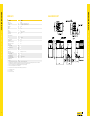
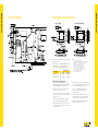
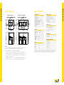
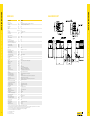
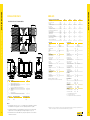
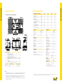
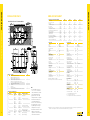
We put all our energy into energy efficiency.
ENER-G CHP
Sustainable heating with maximum efficiency
GAS HP 35A HT
Boiler Model
Product Code
Dimensions W x D x H
Net Weight
Rated Output
Frequency
Voltage
Current
Phase/Wires
Power Factor
Recovered Heat
Hot Water Temperature
Inlet
Outlet
Hot Water Flow Rate
Total Efficiency
Electrical Generation Efficiency
Exhaust Heat Recovery Ratio
Sound Pressure Level for Rated Load
Radiator Fan Stopped
Radiator Fan Operating
—
Voltage
Startup Current
Power Consumption (Rated)
Radiator Fan Stopped
Radiator Fan Operating
Space Heater (below 5°C)
Fuel Consumption (LHV basis)
Gas Supply Pressure
Category 2H
GAS ENGINE UNIT
mm
kg
kW
Hz
V
A
%
kW
ENER-G4
CP4WE
1100 x 500 (570 including protrusion) x 1500 (1555 including cover)
410 (including cooling water and lubricant)
3.87*1
50
230
AC 16.0
Single phase, two wires
97 or more
8.38
°C
°C
L/min
%
%
%
60
65
24.3*2
84.5
26.7
57.8
dB (A)
dB (A)
dB (A)
ACV
A
51
53
—
230
13 (average electric current)
kW
kW
dB (A)
kW
0.19
0.28
0.25 (for cold regions)
14.5*3
mbar
20
REMEHA ENER-G4 TECHNICAL SPECIFICATION
REMEHA ENER-G4 TECHNICAL SPECIFICATION
ENER-G4
1 The heat recovery and efficiency values are those for rated output in standard atmospheric conditions.
2The operating sound levels are maximum values measured in 4 directions at a point 1m from the side of the unit and 1.2m above the ground in an anechoic room simulation.
The sound levels during actual operation are usually higher than the simulated values due to ambient noise and echoes.
3
The values for the external dimensions do not include piping, piping connections, or protruding parts.
4
The amount of fuel consumption is based on lower calorific values.
*1
*2
*3
2
Power consumption is included
Max of +5%; 25.5l/min
Tolerance +5% is not included
3
DIMENSIONAL DRAWING OF BASE
1. Direct Mount
2. Anti-Vibration Mount
When the unit is installed indoors, a syphon (option)
should be installed.
If the back pressure of the exhaust-piping extension
exceeds 500Pa, use a long syphon and make the
height of the base from F.L. to 250mm or more.
Type of Anchor Bolt
Size
L-type/LA-type
Resin
Male screw mechanical
4
Embedded Depth A (mm)
150
M12
Notes:
1 For use of box-out L-type/LA-type bolt.
When laying the concrete for the base, provide a box-out for fixing the
anchor bolts, fix the anchor bolts and then secure them in the concrete.
2It is sometimes necessary to change the thickness of the
base depending on the foundation strength, so carry out
the work after consulting construction engineers.
3Earthquake-resistance strength: Horizontal seismic
coefficient of 0.6 (Numeric values with * show the dimensions
in the case of a horizontal seismic coefficient 1.0).
4When using a smaller base, join the base and
the structure with reinforcing bars.
REMEHA ENER-G4 TECHNICAL SPECIFICATION
REMEHA ENER-G4 TECHNICAL SPECIFICATION
SYSTEM FLOWCHART
90
60
5
1. Single Unit Installation
ENER-G4 DATASHEET
2. Multiple Units Installation
General Description
Heat Recovery System
Fuel Type
Natural Gas
Fully closed primary water circuit
Minimum Methane Number
80
Exhaust gas heat exchanger in primary circuit
Electrical Output
3.9kW
PHE between primary and secondary circuits.
Heat Output (Exhaust Cooled to 69°C)
8kW
Primary water pump
Fuel Input Net/Gross (CV 10kWh/Nm³)
15/16kW
Auto heat output modulation
Min/Max Dynamic Gas Pressure
10/25 mbar
Max Return/Flow Water Temp:
55/65°C
Control and Protection
Unit Efficiency
84.8%
On board computer control, protection and monitoring
Engine stop/start, synchronising, modulation
Prime Mover
Mechanical, electrical and thermal protection
Type
Reciprocating Engine
Combustion Cycle
4-stroke Spark Ignition
Cylinders
3
Speed
2000
NOx Emissions
283 mg/Nm
CO Emissions
36 mg/Nm 3
Aspiration
Natural
BMS interface signals
Standard Equipment
Internal Exhaust silencers
3
Secondary water pump
Optional Equipment/Configuration:
Export control panel
Generator
Notes
1. When surrounding the unit with soundproof walls, attach openings (louvres or the like) to the
bottom of the soundproof walls. (To prevent the short circuits of radiating air).
2. Decide installation space after consideration of the piping space.
3. If the distance of retention is specified by local-government fire prevention ordinances and
enforcement regulations, secure the installation space according to these regulations.
REMEHA ENER-G4 TECHNICAL SPECIFICATION
REMEHA ENER-G4 TECHNICAL SPECIFICATION
INSTALLATION SPACE
Remote monitoring
Type
PMG DC & DC/AC Inverter
Heat and gas metering
Frequency
50 Hz
System controller
Voltage
230 V
Anti-vibration mounts
Phase(s)
1-Phase
Exhaust extension kit
Electrical output is based on output at the generator terminals at a power factor of 0.95. Energy quantities subject to reduction when modulating in response to
external conditions. We reserve the right to alter the Engine Type, at any time, to meet the system specifications. Performance figures are subject to original Engine
manufacturer’s declared performance, tolerances and test conditions. Output figures are based on operation at ISO3046 conditions with the exception of the exhaust
output, temperature stated above. Technical Datasheets are subject to change, without notice, due to our commitment to on-going product improvement.
4. Give consideration not to cause problems for neighbouring houses due to operating noise,
radiating air, or hot ventilation air.
5. Depending on the situation, the site may be filled with radiating air and this has an effect on
performance. Prevent the short circuits with the optional wind direction boards, etc.
6
7
Boiler Model
Product Code
Dimensions W x D x H
Net Weight
Rated Output
Frequency
Voltage
Current
Phase/Wires
Power Factor
Recovered Heat
Hot Water Temperature
Inlet
Outlet
Hot Water Flow Rate
Overall Efficiency
Electrical Generation Efficiency
Exhaust Heat Recovery Ratio
For Rated Load
Radiator Fan Stopped
Radiator Fan Operating
—
Voltage
Startup Current
Power Consumption (Rated)
Radiator Fan Stopped
Radiator Fan Operating
Space Heater (below 5°C)
Fuel Consumption (LHV basis)
Gas Supply Pressure
Category 2H
GAS ENGINE UNIT
mm
kg
kW
Hz
V
A
%
kW
ENER-G10
CP10WE
1470 x 800 (900 including protrusion) x 1790
790 (including cooling water and lubricant)
10.00*1
50
AC400
14
Three phase, four wires
97 or more
17.3
°C
°C
L/min
%
%
%
65
70 (Max 78)
48.2*2
84.0
30.7
53.3
dB (A)
dB (A)
dB (A)
ACV
A
54
56
—
230
22.6 (average electric current)
kW
kW
dB (A)
kW
0.28
0.53
0.50 (for cold regions)
32.6*3
mbar
20
REMEHA ENER-G10 TECHNICAL SPECIFICATION
REMEHA ENER-G10 TECHNICAL SPECIFICATION
ENER-G10
1 The heat recovery and efficiency values are those for rated output in standard atmospheric conditions.
2The operating sound levels are maximum values measured in 4 directions at a point 1m from the side of the unit and 1.2m above the ground in an anechoic room simulation.
The sound levels during actual operation are usually higher than the simulated values due to ambient noise and echoes.
3
The values for the external dimensions do not include piping, piping connections, or protruding parts.
4
The amount of fuel consumption is based on lower calorific values.
5
As for G83, the examination was carried out by New and Renewable Energy Centre (NaREC) in U.K.
*1
*2
*3
8
Power consumption is included
Max of +5%; 50.6l/min
Tolerance +5% is not included
9
DIMENSIONAL DRAWING OF BASE
1. Direct Mount
2. Anti-Vibration Mount
When the unit is installed indoors, a syphon (option)
should be installed.
If the back pressure of the exhaust-piping extension
exceeds 500Pa, use a long syphon and make the
height of the base from F.L. to 250mm or more.
Type of Anchor Bolt
Size
L-type/LA-type
Male screw mechanical
Resin
M12
Embedded Depth A (mm)
Direct Mount
Anti-Vibration Mount
60 or more
70 or more
60 or more
70 or more
30 or more
40 or more
Points to note in constructing the base
1. Set the standard compounding ratio, cement 1:
sand 2: aggregate 4, and insert reinforcing bars of
Ø10 (interval: approx. 300mm) into the base.
2. Finish the surface with mortar so that it is flat.
Chamfer the edges of the concrete.
3. When setting the base on a concrete floor, rubble
is not necessary, but make the concrete surface of
such parts uneven.
4. Build the waterway around the base, and pay
attention to the drainage around the machine.
5. When installing the unit on a rooftop, be careful
about the surface strength, and be sure to make
the area waterproof.
10
Notes:
1 For use of box-out L-type/LA-type bolt.
When laying the concrete for the base, provide a box-out for fixing the
anchor bolts, fix the anchor bolts and then secure them in the concrete.
2It is sometimes necessary to change the thickness of the
base depending on the foundation strength, so carry out
the work after consulting construction engineers.
3Earthquake-resistance strength: Horizontal seismic
coefficient of 0.6 (Numeric values with * show the dimensions
in the case of a horizontal seismic coefficient 1.0).
4When using a smaller base, join the base and
the structure with reinforcing bars.
REMEHA ENER-G10 TECHNICAL SPECIFICATION
REMEHA ENER-G10 TECHNICAL SPECIFICATION
SYSTEM FLOWCHART
6. In places where the soil has a low weight-bearing
capacity (clay layer, sand area, loam layer), be sure
to carry out foundation improvement work.
7. Fix the co-generation main unit with anchor
bolts to prevent falls and to make the base
firm and horizontal.
8. When installing the unit in places such as on a roof,
rooftop or balcony where noise or vibration may
become an issue, use anti-vibration mounts.
9. Observe any relevant local laws and regulations
related to the installation of the unit.
11
1. Single Unit Installation
ENER-G10 DATASHEET
2. Multiple Units Installation
General Description
Heat Recovery System
Fuel Type
Natural Gas
Fully closed primary water circuit
Minimum Methane Number
80
Exhaust gas heat exchanger in primary circuit
Electrical Output
10kW
PHE between primary and secondary circuits.
Heat Output (Exhaust Cooled to 77°C)
17kW
Primary water pump
Fuel Input Net/Gross (CV 10kWh/Nm³)
32/36 kW
Auto heat output modulation
Min/Max Dynamic Gas Pressure
10/25C mbar
Max Return/Flow Water Temp:
68/78°C
Control and Protection
Unit Efficiency
84.5%
On board computer control, protection and monitoring
Engine stop/start, synchronising, modulation
Prime Mover
Mechanical, electrical and thermal protection
Type
Reciprocating Engine
Combustion Cycle
4-stroke Spark Ignition
Cylinders
3
Speed
1700
NOx Emissions
653 mg/Nm
CO Emissions
21 mg/Nm 3
Aspiration
Natural
BMS interface signals
Standard Equipment
Internal Exhaust silencers
3
Secondary water pump
Optional Equipment/Configuration:
Export control panel
Generator
Notes
1. When surrounding the unit with soundproof walls, attach openings (louvres or the like) to the
bottom of the soundproof walls. (To prevent the short circuits of radiating air).
2. Decide installation space after consideration of the piping space.
3. If the distance of retention is specified by local-government fire prevention ordinances and
enforcement regulations, secure the installation space according to these regulations.
REMEHA ENER-G10 TECHNICAL SPECIFICATION
REMEHA ENER-G10 TECHNICAL SPECIFICATION
INSTALLATION SPACE
Remote monitoring
Type
PMG DC & DC/AC Inverter
Heat and gas metering
Frequency
50 Hz
System controller
Voltage
400 V
Anti-vibration mounts
Phase(s)
3-Phase
Exhaust extension kit
Electrical output is based on output at the generator terminals at a power factor of 0.95. Energy quantities subject to reduction when modulating in response to
external conditions. We reserve the right to alter the Engine Type, at any time, to meet the system specifications. Performance figures are subject to original Engine
manufacturer’s declared performance, tolerances and test conditions. Output figures are based on operation at ISO3046 conditions with the exception of the exhaust
output, temperature stated above. Technical Datasheets are subject to change, without notice, due to our commitment to on-going product improvement.
4. Give consideration not to cause problems for neighbouring houses due to operating noise,
radiating air, or hot ventilation air.
5. Depending on the situation, the site may be filled with radiating air and this has an effect on
performance. Prevent the short circuits with the optional wind direction boards, etc.
12
13
Boiler Model
Product Code
Dimensions W x D x H
Net Weight
Rated Output
Frequency
Voltage
Current
Phase/Wires
Power Factor
Recovered Heat
Hot Water Temperature
Outlet
Hot Water Flow Rate
Overall Efficiency
Electrical Generation Efficiency
Exhaust Heat Recovery Ratio
Sound Pressure Level during Rated Load
Radiator Fan Stopped
Radiator Fan Operating
—
Voltage
Startup Current
Power Consumption (Rated)
Radiator Fan Stopped
Radiator Fan Operating
Space Heater (below 5°C)
Fuel Consumption (LHV basis)
Gas Supply Pressure
Natural Gas
Gas Engine
Type
Cylinder Bore x Stroke
Displacement
Rated Output
Engine Speed
Catalyser
Starter System
Lubricant Type
System Lubricant Capacity
Inverter
Rated Output
Main Circuit System Inverter
Main Circuit Switching System
Main Circuit Insulation System
Power Control
Reverse Power Prevention Control
Coolant
Concentration of Coolant - Standard
Concentration of Coolant - Cold Area
Cooling Water Capacity
Cooling Water Pump Type
Generator Type
Phase/Wires
Number of Poles
Excitation System
Insulation Class / Armature Coil
Bearing System
Transformer for Starting Input Voltage
Electric Motor for Starting
Heat Exchanger Type
Heat Exchanger Plate Material
Pressure Proof Secondary Side
Maintenance Interval
Conditions for Use
Ambient Temperature
Relative Humidity
Altitude (above sea level)
GAS ENGINE UNIT
mm
kg
kW
Hz
V
A per phase
%
kW
ENER-G25
CP25WE
2150 x 800 (900 including protrusion) x 2010 (2060 including cover)
1320 (including cooling water and lubricant)
25.0
50
400
35.4
Three phase, four wires
97 or more
38.4
°C
L/min
%
%
%
Max 85
110
85.0
33.5
51.5
dB (A)
dB (A)
dB (A)
V
A
62
64
—
AC 200
46.0 (average electric current)
kW
kW
dB (A)
kW
0.93
1.35
0.75 (for cold regions)
74.6
kPa
mm
L
kW
min-1
L
kW
%
%
V
V
MPa
Hours
°C
%
m
1.5 ~ 3.0
4GPF98-C1
Vertical cylinder, 4-cycle water-cooled gas engine
4
3.318
27.3
1,900
Oxiside Catalyser
Electric starting by AC/DC conversion
YANMAR’s Genuine T Oil for GHP (10W30)
66 (including 40 sub-tanks and 26 main tanks)
GS Yuasa Corporation LGU-25-T3E
25
Self-excited voltage-type current control system
PWM System
Non-insulated transformer-less system (Pressure rising chopper system)
Output power constant control system
Reverse power flow prevention control by measuring reverse power flow
Coolant H209 for cogeneration
50
60
31.5 (including the reserve tank)
Magnet driving system spiral type
Open type
Three-phase, three-wires
16
Permanent magnet system
F type
Bearingless
AC200
DC12
Brazing plate system
Stainless
0.8
10,000
REMEHA ENER-G25 TECHNICAL SPECIFICATION
REMEHA ENER-G25 TECHNICAL SPECIFICATION
ENER-G25
-5 ~ +40 (for cold area -15 ~ +40)
80 or less
300 or less
1 The heat recovery and efficiency values are those for rated output in standard atmospheric conditions.
2The operating sound levels are maximum values measured in 4 directions at a point 1m from the side of the unit and 1.2m above the ground in an anechoic room simulation.
The sound levels during actual operation are usually higher than the simulated values due to ambient noise and echoes.
3
The values for the external dimensions do not include piping, piping connections, or protruding parts.
4
The amount of fuel consumption is based on lower calorific values.
14
*1
*2
*3
Power consumption is included
Max of +5%; 116l/min
Tolerance +5% is not included
15
DIMENSIONAL DRAWING OF BASE
1. Direct Mount
2. Anti-Vibration Mount
When the unit is installed indoors, a syphon (option)
should be installed.
If the back pressure of the exhaust-piping extension
exceeds 500Pa, use a long syphon and make the
height of the base from F.L. to 250mm or more.
Type of Anchor Bolt
Size
L-type/LA-type
Resin
Male screw mechanical
16
M12
Embedded Depth A (mm)
Direct Mount
Anti-Vibration Mount
90mm min.
120mm min.
50mm min.
60mm min.
80mm min.
80mm min.
Notes:
1 For use of box-out L-type/LA-type bolt.
When laying the concrete for the base, provide a box-out for fixing the
anchor bolts, fix the anchor bolts and then secure them in the concrete.
2It is sometimes necessary to change the thickness of the
base depending on the foundation strength, so carry out
the work after consulting construction engineers.
3Earthquake-resistance strength: Horizontal seismic
coefficient of 0.6 (Numeric values with * show the dimensions
in the case of a horizontal seismic coefficient 1.0).
4When using a smaller base, join the base and
the structure with reinforcing bars.
REMEHA ENER-G25 TECHNICAL SPECIFICATION
REMEHA ENER-G25 TECHNICAL SPECIFICATION
SYSTEM FLOWCHART
17
1. Single Unit Installation
ENER-G25 DATASHEET
2. Multiple Units Installation
General Description
Heat Recovery System
Fuel Type
Natural Gas
Fully closed primary water circuit
Minimum Methane Number
80
Exhaust gas heat exchanger in primary circuit
Electrical Output
25kW
PHE between primary and secondary circuits
Heat Output (Exhaust Cooled to 124°C)
38kW
Primary water pump
Fuel Input Net/Gross (CV 10kWh/Nm³)
75/82 kW
Auto heat output modulation
Min/Max Dynamic Gas Pressure
15/30 mbar
Max Return/Flow Water Temp:
75/85°C
Control and Protection
Unit Efficiency
85.2%
On board computer control, protection and monitoring
Engine stop/start, synchronising, modulation
Prime Mover
Mechanical, electrical and thermal protection
Type
Reciprocating Engine
Combustion Cycle
4-stroke Spark Ignition
Cylinders
4
Speed
1900
NOx Emissions
542 mg/Nm
CO Emissions
634 mg/Nm 3
Aspiration
Natural
BMS interface signals
Standard Equipment
Internal Exhaust silencers
3
Secondary water pump
Optional Equipment/Configuration:
Export control panel
Generator
Notes
1. When surrounding the unit with soundproof walls, attach openings (louvres or the like) to the
bottom of the soundproof walls. (To prevent the short circuits of radiating air).
2. Decide installation space after consideration of the piping space.
3. If the distance of retention is specified by local-government fire prevention ordinances and
enforcement regulations, secure the installation space according to these regulations.
4. Give consideration not to cause problems for neighbouring houses due to operating noise,
radiating air, or hot ventilation air.
REMEHA ENER-G25 TECHNICAL SPECIFICATION
REMEHA ENER-25 TECHNICAL SPECIFICATION
INSTALLATION SPACE
Remote monitoring
Type
PMG DC & DC/AC Inverter
Heat and gas metering
Frequency
50 Hz
System controller
Voltage
400 V
Anti-vibration mounts
Phase(s)
3-Phase
Exhaust extension kit
Electrical output is based on output at the generator terminals at a power factor of 0.95. Energy quantities subject to reduction when modulating in response to
external conditions. We reserve the right to alter the Engine Type, at any time, to meet the system specifications. Performance figures are subject to original Engine
manufacturer’s declared performance, tolerances and test conditions. Output figures are based on operation at ISO3046 conditions with the exception of the exhaust
output, temperature stated above. Technical Datasheets are subject to change, without notice, due to our commitment to on-going product improvement.
5. Depending on the situation, the site may be filled with radiating air and this has an effect on
performance. Prevent the short circuits with the optional wind direction boards, etc.
18
19
ENER-G35
Energy Balance and Part Load Data @ 0.95PF
Installation Clearance Recommendations
Electrical Output
Electrical Efficiency (Net)
Heat Output
Thermal Efficiency (Net)
Fuel Input (Net)
Total Efficiency (Net)
Heat Output from Jacket Water
Heat Output from Exhaust Gas @ Outlet Temp.
Aftercooler Heat Output
Radiated Heat Output
Combustion Air Flow
Fuel Mass Flow (p = 0.75kg/Nm 3)
Fuel Volume Flow (LHV = 10kWh/Nm 3)
Exhaust Mass Flow (Wet)
Exhaust Volume Flow @ Outlet Temp
Engine Details
Manufacturer
Model
Fuel Type
Min. Methane Number
Cylinders
Aspiration
Speed
Aftercooler
Hot Water Details
Max. Water In/Out Temp.
Max. Water Flow Rate*
Max. Glycol Content
Connection Size
Flange Type
Pressure Loss**
Max. Test Pressure
Exhaust Details
Connection Size
Flange Type
Outlet Temp.
Max. Allowable Back pressure
Ventilation Details
Connection Size
Ventilation Rate
Max. Air Inlet Temp.
Max. Air Outlet Temp.
Item No.
Description
1
2
3
4
100NS PN6 Flanged Exhaust CHP Outlet
25NS PN16 Flanged Natural Gas CHP Inlet
40NS PN16 Flanged Heating Water CHP Inlet
40NS PN16 Flanged Heating Water CHP Outlet
Enclosure Fan Outlet Ø400 with 8x Ø12 Holes Equally Spaced on
450mm P.C.D.
Oil Fill Point
Control Panel
Main Cable Gland Plate
Anti-Vibration Mounts and Removable Pick up Plates (if required)
5
6
7
8
9
Enclosure Type
Total Dry Weight kg (Approx)
Standard
Premium
2450kg
2550kg
Qty
1
1
1
1
1
1
1
1
6
Total Wet Weight kg (Approx)
Units
100%
75%
50%
kW
%
kW
%
kW
%
kW
kW
kW
kW
Nm 3/h
kg/h
Nm 3/h
kg/h
m 3/h
35
31.2
62
55.1
112
86.2
38
24
N/A
9
106
8.4
11.2
146
162
26
28.7
52
56.6
92
85.3
34
18
N/A
7
87
6.9
9.2
119
132
18
24.7
42
59.1
71
83.8
29
13
N/A
5
67
5.3
7.1
92
102
Generator Details
rpm
°C
l/s
%
mm
kPa
Bar
mm
MAN
E 0834 E 302
Natural Gas
80
4
Natural
1500
No
80/90
1.56
0
50
PN16
4
10
°C
Bar
100
PN6
120
10
mm
m2 /s
°C
°C
500
0.79
30
45
*Assuming Cp = 3.91 kj/kg·K and p = 1014.64 kg/m3
**Pressure loss figures stated are at max. water flow rate. Internal unit only.
Manufacturer
Model
Type
Rating
Voltage
Phase
Frequency
Protection Class
Rated Power Factor
Xd Dir. Axis Synchronous
X’d Dir. Axis Transient
X”d Dir Axis Sub-Transient
T”Sub-Transient Time. Const.
T’do O.C. Field Time Const.
CHP Protection Device
Indicative Client Protection Device
Current Per Phase @ 0.8PF
Current Per Phase @ 0.95PF
Efficiency @ 0.8PF
Efficiency @ 0.95PF
Indicative Main Cable Sizea†
Indicative Earth Cable Sizeb†
Fuel Details
Connection Size
Flange Type
Min/Max Supply Pressure
Emissions @ 5% O2
NOx
CO
NOx (with catalyst)
CO (with catalyst)
Weight Details
Enclosure (Dry) STD/PREM
Container (Dry) STD/PREM
Noise Data
Enclosure SPL @ 1m SN/LN
Container SPL @ 1m SN/LN
kVA
V
Ph
Hz
PF
A/Ph
A/Ph
A
A
%
%
mm2
mm2
mm
Meccalite
ECO 32-3L/4
Synchronous
75
400
3
50
IP21
0.8
305.4
13.4
7
0.0135
1.3
80
80 (Adjustable)
63
53
90.3
91.1
TBC
TBC
mbar
40
PN16
20/45
mg/Nm2
mg/Nm2
mg/Nm2
mg/Nm2
6500
6500
250
350
kg
kg
dB(A)
dB(A)
3000/4000
7100/7600
70/65
75/65
a 4-Core XLPE/SWA/PVC to BS5467, max 50 metres.
b
1-Core 6491B to BS7211, max 50 metres.
†
Sizes and lengths based on IET 17th Edition BS7671, Installation method 31.
2600kg
2700kg
Notes
1. Recommended clearance for service access is 1000mm on sides, 1250mm above, 1000mm at
front and 1500mm at rear (pipework connections end) although 1000mm is acceptable.
2. Consideration must be given on installation design as to whether acoustic treatment may be
required to fans etc. which may add height to the design although this is site specific.
20
(+/-3%)
(+/-5%)
(+/-10%)
(+/-8%)
(+/-5%)
(+/-8%)
(+/-8%)
(+/-8%)
(+/-8%)
(+/-8%)
(+/-5%)
(+/-5%)
(+/-5%)
(+/-5%)
(-+/-5%)
REMEHA ENER-G35 TECHNICAL SPECIFICATION
REMEHA ENER-G35 TECHNICAL SPECIFICATION
INSTALLATION SPACE
3. Anti-vibration mounts are shown hidden as they may not be required on certain sites and are
removable for installation.
NB: Energy balance data assumes perfect combustion. Values for part load are estimates only. All information detailed is for guidance only and is subject to change without notice due to our
commitment to continuous improvement – all values should be confirmed with ENER-G Combined Ltd on a project specific basis.
21
ENER-G50 DATASHEET
Energy Balance and Part Load Data @ 0.95PF
Installation Clearance Recommendations
Electrical Output
Electrical Efficiency (Net)
Heat Output
Thermal Efficiency (Net)
Fuel Input (Net)
Total Efficiency (Net)
Heat Output from Jacket Water
Heat Output from Exhaust Gas @ Outlet Temp.
Aftercooler Heat Output
Radiated Heat Output
Combustion Air Flow
Fuel Mass Flow (p = 0.75kg/Nm 3)
Fuel Volume Flow (LHV = 10kWh/Nm 3)
Exhaust Mass Flow (Wet)
Exhaust Volume Flow @ Outlet Temp
Engine Details
Item No.
Description
1
2
3
4
100NS PN6 Flanged Exhaust CHP Outlet
25NS PN16 Flanged Natural Gas CHP Inlet
40NS PN16 Flanged Heating Water CHP Inlet
40NS PN16 Flanged Heating Water CHP Outlet
Enclosure Fan Outlet Ø400 with 8x Ø12 Holes Equally Spaced on
450mm P.C.D.
Combustion Air Inlet Attenuator
Oil Fill Point
Control Panel
Main Cable Gland Plate
Anti-Vibration Mounts and Removable Pick up Plates (if required)
5
6
7
8
9
10
Enclosure Type
Total Dry Weight kg (Approx)
Standard
Premium
2450kg
2550kg
Qty
1
1
1
1
1
1
1
1
6
Total Wet Weight kg (Approx)
2600kg
2700kg
Notes
1. Recommended clearance for service access is 1000mm on sides, 1250mm above, 1000mm at
front and 1500mm at rear (pipework connections end) although 1000mm is acceptable.
2. Consideration must be given on installation design as to whether acoustic treatment may be
required to fans etc. which may add height to the design although this is site specific.
22
(+/-3%)
(+/-5%)
(+/-10%)
(+/-8%)
(+/-5%)
(+/-8%)
(+/-8%)
(+/-8%)
(+/-8%)
(+/-8%)
(+/-5%)
(+/-5%)
(+/-5%)
(+/-5%)
(-+/-5%)
3. Anti-vibration mounts are shown hidden as they may not be required on certain sites and are
removable for installation.
Manufacturer
Model
Fuel Type
Min. Methane Number
Cylinders
Aspiration
Speed
Aftercooler
Hot Water Details
Max. Water In/Out Temp.
Max. Water Flow Rate*
Max. Glycol Content
Connection Size
Flange Type
Pressure Loss**
Max. Test Pressure
Exhaust Details
Connection Size
Flange Type
Outlet Temp.
Max. Allowable Back pressure
Ventilation Details
Connection Size
Ventilation Rate
Max. Air Inlet Temp.
Max. Air Outlet Temp.
Units
100%
75%
50%
kW
%
kW
%
kW
%
kW
kW
kW
kW
Nm 3/h
kg/h
Nm 3/h
kg/h
m 3/h
50
33.7
79
53.4
148
87.1
46
33
N/A
12
140
11.1
14.8
192
214
37
31.7
65
54.8
118
86.5
39
25
N/A
9
112
8.9
11.8
153
171
25
28.2
50
56.9
89
85.1
33
17
N/A
7
84
6.6
8.9
115
128
Generator Details
rpm
°C
l/s
%
mm
kPa
Bar
mm
MAN
E 0834 E 302
Natural Gas
80
4
Natural
1500
No
80/90
1.99
0
50
PN16
8.3
10
°C
Pa
100
PN6
120
2640
mm
m2 /s
°C
°C
500
1.01
30
45
*Assuming Cp = 3.91 kj/kg·K and p = 1014.64 kg/m3
**Pressure loss figures stated are at max. water flow rate. Internal unit only.
Manufacturer
Model
Type
Rating
Voltage
Phase
Frequency
Protection Class
Rated Power Factor
Xd Dir. Axis Synchronous
X’d Dir. Axis Transient
X”d Dir Axis Sub-Transient
T”Sub-Transient Time. Const.
T’do O.C. Field Time Const.
CHP Protection Device
Indicative Client Protection Device
Current Per Phase @ 0.8PF
Current Per Phase @ 0.95PF
Efficiency @ 0.8PF
Efficiency @ 0.95PF
Indicative Main Cable Sizea†
Indicative Earth Cable Sizeb†
Fuel Details
Connection Size
Flange Type
Min/Max Supply Pressure
Emissions @ 5% O2
NOx
CO
NOx (with catalyst)
CO (with catalyst)
Weight Details
Enclosure (Dry) STD/PREM
Container (Dry) STD/PREM
Noise Data
Enclosure SPL @ 1m SN/LN
Container SPL @ 1m SN/LN
kVA
V
Ph
Hz
PF
A/Ph
A/Ph
A
A
%
%
mm2
mm2
mm
Meccalite
ECO 32-3L/4
Synchronous
75
400
3
50
IP21
0.8
305.4
13.4
7
0.0135
1.3
100
100 (Adjustable)
89
76
91.1
92.4
TBC
TBC
mbar
40
PN16
20/45
mg/Nm2
mg/Nm2
mg/Nm2
mg/Nm2
6500
6500
250
350
kg
kg
dB(A)
dB(A)
REMEHA ENER-G50 TECHNICAL SPECIFICATION
REMEHA ENER-G50
ENER-G4 TECHNICAL
TECHNICALSPECIFICATION
SPECIFICATION
INSTALLATION SPACE
3000/4000
7100/7600
70/65
75/65
a 4-Core XLPE/SWA/PVC to BS5467, max 50 metres.
b
1-Core 6491B to BS7211, max 50 metres.
†
Sizes and lengths based on IET 17th Edition BS7671, Installation method 31.
NB: Energy balance data assumes perfect combustion. Values for part load are estimates only. All information detailed is for guidance only and is subject to change without notice due to our
commitment to continuous improvement – all values should be confirmed with ENER-G Combined Ltd on a project specific basis.
23
ENER-G70 DATASHEET
Installation Clearance Recommendations
General Description
Control and Protection
Enclosure Type
Internal
On board computer control, protection and monitoring
Fuel Type
Natural Gas
Engine stop/start, synchronising, modulation
Minimum Methane Number
80
Mechanical, electrical and thermal protection
Electrical Output
70kW
70+ parameters monitored, historical data recorded
Heat Output (Exhaust Cooled to 120°C)
109kW
2 way communication between unit and head office
Fuel Input Net/Gross (CV 10kWh/Nm³)
204/226kW
BMS interface signals
Min/Max Dynamic Gas Pressure
20/45mbar
Max Return/Flow Water Temp:
80/90°C
Standard Equipment
Exhaust silencers (industrial and residential grade)
Prime Mover
Secondary water pump
Type
Reciprocating Engine
Combustion Cycle
4-stroke Spark Ignition
Optional Equipment/Configuration:
Cylinders
6
Heat rejection equipment/controls
Speed
1500
NOx Emissions with/without Cat
250/7000 mg/Nm
CO Emissions with/without Cat
350/5000 mg/Nm 3
Heat and gas metering
Aspiration
Natural
Modbus Interface Card
Low noise acoustic enclosure/container
3
Export control panel
Catalytic converters for very low emissions
Generator
REMEHA ENER-G70 TECHNICAL SPECIFICATION
REMEHA ENER-G70 TECHNICAL SPECIFICATION
INSTALLATION SPACE
Generator only (no heat recovery)
Type
Synchronous
Island mode operation
Frequency
50 Hz
CHP absorption chiller packages
Voltage
400 V
Efficiency
94.1%
Heat Recovery System
Fully closed primary water circuit
Item No.
Description
1
2
3
4
5
100NS PN6 Flanged Exhaust CHP Outlet
40NS PN16 Flanged Natural Gas CHP Inlet
50NS PN16 Flanged Heating Water CHP Inlet
50NS PN16 Flanged Heating Water CHP Outlet
Combustion Air Inlet Filter (Removable for Installation)
Enclosure Fan Outlet Ø500 with 12No. x Ø12 Holes Equally Spaced on
560mm P.C.D. (Removable for Installation)
Oil Fill Point
Control Panel
Main Cable Gland Plate
Anti-Vibration Mounts and Removable Pick up Plates (if required)
Catalyst Door Bulge in Enclosure (If Catalyst is Required)
6
7
8
9
10
11
Enclosure Type
Totally Dry Weight kg (Approx)
Standard
Premium
3000kg
3200kg
Qty
1
1
1
1
1
1
1
1
1
6
1
Exhaust gas heat exchanger in primary circuit
PHE between primary and secondary circuits
Primary water pump
Auto heat output modulation
Electrical output is based on output at the generator terminals at a power factor of 0.95. Energy quantities subject to reduction when modulating in response to
external conditions. We reserve the right to alter the Engine Type, at any time, to meet the system specifications. Performance figures are subject to original Engine
manufacturer’s declared performance, tolerances and test conditions. Output figures are based on operation at ISO3046 conditions with the exception of the exhaust
output, temperature stated above. Technical Datasheets are subject to change, without notice, due to our commitment to on-going product improvement.
Total Wet Weight kg (Approx)
3170kg
3370kg
Notes
1. Recommended clearance for service access is 1000mm on sides, 1250mm above, 1000mm at
front and 1500mm at rear (pipework connections end) although 1000mm is acceptable.
2. Consideration must be given on installation design as to whether acoustic treatment may be
required to fans etc. which may add height to the design although this site is site specific.
24
3. Anti-vibration mounts are shown hidden as they may not be required on certain sites and are
removable for installation.
4. Bulge in door is shown hidden due to it is only required on units fitted with a catalyst. If no catalyst
is fitted then the door remains flush.
25
ENER-G90 DATASHEET
Energy Balance and Part Load Data @ 0.95PF
Installation Clearance Recommendations
Electrical Output
Electrical Efficiency (Net)
Heat Output
Thermal Efficiency (Net)
Fuel Input (Net)
Total Efficiency (Net)
Heat Output from Jacket Water
Heat Output from Exhaust Gas @ Outlet Temp.
Aftercooler Heat Output
Radiated Heat Output
Combustion Air Flow
Fuel Mass Flow (p = 0.75kg/Nm 3)
Fuel Volume Flow (LHV = 10kWh/Nm 3)
Exhaust Mass Flow (Wet)
Exhaust Volume Flow @ Outlet Temp
Engine Details
Item No.
Description
1
2
3
4
5
125NS PN16 Flanged Exhaust CHP Outlet
40NS PN16 Flanged Natural Gas CHP Inlet
50NS PN16 Flanged Heating Water CHP Inlet
50NS PN16 Flanged Heating Water CHP Outlet
Combustion Air Inlet Filter (Removable for Installation)
Enclosure Fan Outlet Ø500 with 12No. x Ø12 Holes Equally Spaced on
560mm P.C.D. (Removable for Installation)
Oil Fill Point
Control Panel
Main Cable Gland Plate
Anti-Vibration Mounts and Removable Pick up Plates (if required)
6
7
8
9
10
Dimension Ref.
Standard
Premium
A
B
C
D
E
F
G
H
J
K
L
3600mm
1940mm
930mm
3700mm
369mm
145mm
680mm
250mm
950mm
2295mm
1200mm
3650mm
1990mm
1030mm
3725mm
419mm
195mm
730mm
300mm
1050mm
2345mm
1300mm
M
30mm
30mm
1400mm
3500kg
3700kg
1500mm
3900kg
4100kg
N
Total Weight
Total Weight
Manufacturer
Model
Fuel Type
Min. Methane Number
Cylinders
Aspiration
Speed
Aftercooler
Hot Water Details
Max. Water In/Out Temp.
Max. Water Flow Rate*
Max. Glycol Content
Connection Size
Flange Type
Pressure Loss**
Max. Test Pressure
Exhaust Details
Connection Size
Flange Type
Outlet Temp.
Max. Allowable Back pressure
Ventilation Details
Connection Size
Ventilation Rate
Max. Air Inlet Temp.
Max. Air Outlet Temp.
Qty
1
1
1
1
1
Shipping & Install Notes
Shipping Height
Shipping & Installation Length
Shipping & Installation Width
Installation Height Exc. Ductwork
(*)Approx Floating Clearance
Dimension When Loaded
Approx. Dry Weight (kg)
Approx. Wet Weight (kg)
Notes
1. Recommended clearance for
service access is 1000mm on
sides, 1250mm above, 1000mm
at front and 1500mm at rear
(pipework connections end)
although 1000mm is acceptable.
2. Consideration must be given
on installation design as to
whether acoustic treatment may
be required to fans etc. which
may add height to the design
although this is site specific.
3. Anti-vibration mounts are shown
hidden as they may not be
required on certain sites and are
removable for installation.
Units
100%
75%
50%
kW
%
kW
%
kW
%
kW
kW
kW
kW
Nm 3/h
kg/h
Nm 3/h
kg/h
m 3/h
90
32.2
161
57.6
280
89.8
110
51
N/A
10
266
21.0
28.0
368
410
68
29.8
136
59.8
227
89.6
97
39
N/A
8
215
17.0
22.7
298
332
45
26.0
110
63.3
173
89.2
83
27
N/A
6
165
13.0
17.3
228
254
Generator Details
rpm
°C
l/s
%
mm
kPa
Bar
mm
ENER-G
EGE-06L
Natural Gas
70
6
Natural
1500
No
80/90
4.06
30
50
PN16
11
10
°C
Pa
125
PN16
120
3570
mm
m2 /s
°C
°C
500
1.24
30
45
*Assuming Cp = 3.91 kj/kg·K and p = 1014.64 kg/m3
**Pressure loss figures stated are at max. water flow rate. Internal unit only.
1
1
1
1
6
CHP Enclosure Type Dimension Table
26
(+/-3%)
(+/-5%)
(+/-10%)
(+/-8%)
(+/-5%)
(+/-8%)
(+/-8%)
(+/-8%)
(+/-8%)
(+/-8%)
(+/-5%)
(+/-5%)
(+/-5%)
(+/-5%)
(-+/-5%)
Manufacturer
Model
Type
Rating
Voltage
Phase
Frequency
Protection Class
Rated Power Factor
Xd Dir. Axis Synchronous
X’d Dir. Axis Transient
X”d Dir Axis Sub-Transient
T”Sub-Transient Time. Const.
T’do O.C. Field Time Const.
CHP Protection Device
Indicative Client Protection Device
Current Per Phase @ 0.8PF
Current Per Phase @ 0.95PF
Efficiency @ 0.8PF
Efficiency @ 0.95PF
Indicative Main Cable Sizea†
Indicative Earth Cable Sizeb†
Fuel Details
Connection Size
Flange Type
Min/Max Supply Pressure
Emissions @ 5% O2
NOx
CO
NOx (with catalyst)
CO (with catalyst)
Weight Details
Enclosure (Dry) STD/PREM
Container (Dry) STD/PREM
Noise Data
Enclosure SPL @ 1m SN/LN
Container SPL @ 1m SN/LN
kVA
V
Ph
Hz
PF
A/Ph
A/Ph
A
A
%
%
mm2
mm2
mm
Stamford
UCI274H-311
Synchronous
200
400
3
50
IP23
0.8
1.91
0.16
0.11
0.012
1.1
160
160 (Adjustable)
162
137
93.9
94.9
TBC
TBC
mbar
40
PN16
20/55
mg/Nm2
mg/Nm2
mg/Nm2
mg/Nm2
3676
2163
250
350
kg
kg
dB(A)
dB(A)
REMEHA ENER-G90 TECHNICAL SPECIFICATION
REMEHA ENER-G90 TECHNICAL SPECIFICATION
INSTALLATION SPACE
4600/6000
TBC/TBC
70/65
75/65
a 4-Core XLPE/SWA/PVC to BS5467, max 50 metres.
b
1-Core 6491B to BS7211, max 50 metres.
†
Sizes and lengths based on IET 17th Edition BS7671, Installation method 31.
NB: Energy balance data assumes perfect combustion. Values for part load are estimates only. All information detailed is for guidance only and is subject to change without notice due to our
commitment to continuous improvement – all values should be confirmed with ENER-G Combined Ltd on a project specific basis.
27
Remeha Commercial
Innovation House
3 Oaklands Business Centre
Oaklands Park
Wokingham
RG41 2FD
T: 0118 978 3434
[email protected]
www.remeha.co.uk
September 2014
DENSING
G
SING
HIGH
HIGH
EFFICIENCY
HIGH
EFFICIENCY
EFFICIENCY
FULLY
FULLY
MODULATING
FULLY
MODULATING
MODULATING
=°C
/71°C
82/71°C 106.4%
106.4%
106.4%
NCVNCV
ATNCV
50/30°C
AT 50/30°C
AT 50/30°C BOILER
BOILER
BOILER
CONTROL
CONTROL
CONTROL
Blue
BlueEfficiency
Efficiency
TreadLightly
TreadLightly
Blue
BlueEfficiency
Efficiency
TreadLightly
TreadLightly
CCLLEEAANNEERR/ /GGRREEEENNEERR/ /SSMMAARRT TEERR
CCLLEEAANNEERR/ /GGRREEEENNEERR/ /SSMMAARRT TEERR
PREMIX
PREMIX
PREMIX
BURNER
BURNER
BURNER
CLEAN
CLEAN
CLEAN
COMBUSTION
COMBUSTION
COMBUSTION
SUPER
CONDENSING
ULTRA
ULTRA
LOW
ULTRA
LOW
NOx
LOW
NOxNOx
107%
NCV
= 82/71°C
BREEAM
BREEAM
BREEAM
EXCELLENT
EXCELLENT
EXCELLENT
HIGH
EFFICIENCY
RECYCLABLE
RECYCLABLE
RECYCLABLE
106.4%
NCV AT 50/30°C
MATERIALS
MATERIALS
MATERIALS
OONNT THHEEPPLLAANNEET T
OONNT THHEEPPLLAANNEET T
FULLY
MODULATING
SUPER
CONDENSING
BOILER
CONTROL
107% NCV
= 82/71°C
PREMIX
BURNER
HIGH EFFICIENCY
CLEAN
COMBUSTION
106.4%
NCV AT 50/30°C
ULTRA
LOW
NOx
SUPER
CONDENSING
FULLY
MODULATING
BREEAM
EXCELLENT
107%
NCV
= 82/71°C
BOILER
CONTROL
RECYCLABLE
HIGH EFFICIENCY
PREMIX
BURNER
MATERIALS
106.4%
NCV AT 50/30°C
CLEAN
COMBUSTION
FULLY MODULATING
ULTRA
LOW NOx
BOILER
CONTROL
BREEAM
EXCELLENT
P
RE
CLE
M