1
Ramsey Electronics Model No.
RR1
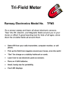
Have you ever been so frustrated with the range of your remote
that you go to the extreme of rearranging your entertainment
room just to make it work? Tired of having to bounce your IR
remote off of ceilings and walls? Do you want to run your
system from another room? Here is the answer to your prayers!
Extend the range of your remote controls as far as you need;
it’s only limited by the length of wire you use!
•
IR receiver module with sensitive element can receive your
remote control up to 36 feet away before re-broadcasting it.
•
The RR1 reconstitutes the receive signal using a PIC micro
controller, restores noisy or weak signals, and then re-broadcasts
the IR remote signals to your components via a long wire (tested
over 500 feet!) to a high-efficiency IR LED.
•
Extend the range of your remote control around corners or down
floors by running a wire to an IR LED in front of the components
you wish to control.
•
Works with almost any remote control (38 kHz carrier), does not
need to be programmed.
•
Will operate from 8V to 16V AC or DC. Use our AC125 wall adapter
for long operation.
•
LED indicator lets you know when you are receiving an IR signal
or not.
RR1 • 1
RAMSEY TRANSMITTER KITS
• FM100B Professional FM Stereo Transmitter
• FM25B Synthesized Stereo FM Transmitter
• MR6 Model Rocket Tracking Transmitter
• TV6 Television Transmitter
• RR1 Wired Remote Repeated
• RRW1 Wireless Remote Repeater
RAMSEY RECEIVER KITS
• FR1 FM Broadcast Receiver
• AR1 Aircraft Band Receiver
• SR2 Shortwave Receiver
• SC1 Shortwave Converter
RAMSEY HOBBY KITS
• SG7 Personal Speed Radar
• SS70A Speech Scrambler
• BS1 “Bullshooter” Digital Voice Storage Unit
• AVS10 Automatic Sequential Video Switcher
• WCT20 Cable Wizard Cable Tracer
• ECG1 Electrocardiogram Heart Monitor
• LABC1 Lead Acid Battery Charger
• LC1 Inductance-Capacitance Meter
RAMSEY AMATEUR RADIO KITS
• DDF1 Doppler Direction Finder
• HR Series HF All Mode Receivers
• QRP Series HF CW Transmitters
• CW7 CW Keyer
• CPO3 Code Practice Oscillator
• QRP Power Amplifiers
RAMSEY MINI-KITS
Many other kits are available for hobby, school, Scouts and just plain FUN. New
kits are always under development. Write or call for our free Ramsey catalog.
RR1 KIT INSTRUCTION MANUAL
Ramsey Electronics publication No. MRR1 Rev 1.1
First printing: January 2002 MRW
COPYRIGHT 2002 by Ramsey Electronics, Inc. 590 Fishers Station Drive, Victor, New York
14564. All rights reserved. No portion of this publication may be copied or duplicated without the
written permission of Ramsey Electronics, Inc. Printed in the United States of America.
RR1 • 2
Ramsey Publication No. MRR1
Price $5.00
KIT ASSEMBLY
AND INSTRUCTION MANUAL FOR
RR1 REMOTE REPEATER
KIT
TABLE OF CONTENTS
Introduction ...........................................4
Theory of Operation ..............................5
Learn As You Build Strategy .................7
Parts List ...............................................9
Assembly Instructions .........................10
Testing the RR1 ..................................13
Using your RR1 ...................................14
Troubleshooting Guide ........................15
RR1 Schematic ...................................16
RR1 Parts Layout ................................17
Specifications ......................................18
Warranty ..............................................19
RAMSEY ELECTRONICS, INC.
RAMSEY ELECTRONICS, INC.
590 Fishers Station Drive
793 Canning Parkway
Victor, New York 14564
Victor, New York 14564
Phone (585) 924-4560
Phone (585) 924-4560
Fax (585) 924-4555
Fax (585) 924-4555
www.ramseykits.com
RR1 • 3
RR1 INTRODUCTION
Welcome to the RR1 kit (and if you don’t have the time, the wired and tested
version). Let’s take a moment to help you understand the basic workings of IR
remote controls and how the RR1 works. This will better help you understand
what you are about to build. As simple as it may look, the RR1 is one of the
best remote repeaters money can buy thanks to some specialized technology
we have added to restore normally unusable signals. We will get more into that
in the circuit description section.
The RR1 has multiple uses. A common application is to extend the normal
range of your remote control by receiving your remote’s signal and then rebroadcasting it a distance away via a wired IR element. Many stereo
component manufacturers skimp on the IR receiver sections of their equipment
so the range of the remote is very poor. Have you ever thrown your remote at
the power switch because the darn thing wouldn't work from across the room?!.
This kit helps to surmount that very problem. Another common use is to control
your unsightly stereo components that are hidden within a cabinet while you’re
entertaining. The unit allows your remote to control these items while they are
tucked away inside of a cabinet (or even locked away for security reasons) with
only the RR1 exposed so it can relay the information!
To use my house as an example, the stereo components are positioned
behind the couch and it is very cumbersome to have to reach way up with the
remote and beam it backwards in order to control them. Half the time it doesn’t
work even work for me because the batteries keep popping out of the remote (I
lost the remote’s back plate a long time ago in one of the many apartments I’ve
rented in the past, but that’s another story)! I don’t want to have to re-arrange
the room (that is the Wife won’t let me!) just so the remote will work better.
Instead I use the RR1 in front of the couch someplace and have it relay the
signal back to the equipment for me.
To increase the effectiveness of this kit, we take advantage of a highsensitivity IR receiver element which claims on its specification sheet to work
up to 36 feet (11 meters) away from the remote control (that’s about 30 feet
further than my VCR remote works!). Now I can truly atrophy on the couch
when my favorite program comes on and feel the pounds start packing on!
“Hey… another bag of chips when you get a chance Honey!!”
RR1 • 4
RR1 THEORY OF OPERATION
The RR1 may look simple but there is actually quite a lot being done inside
each one of the parts. Many individual components are packed inside of the
IR receiver part (U2) itself; so many in fact that if it was built up with discrete
components, it would never fit in this little kit case. Inside of the part there is
an IR detector diode, amplifier, AGC circuit, bandpass filter, a peak-hold circuit, an integrator, comparators, and an output amplifier. Heck, the part is a kit
in itself! Just be glad it’s all in one nice module and ready to go.
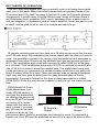
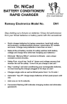
IR remote controls send out their data on a 38 kHz carrier much like the way
your FM radio does. By modulating the carrier signal with the data you want to
send, it is possible to increase the range of the transmission and decrease interference from other IR sources like ambient light (the sun pumps out lots of
IR!!!). The modulation style used with remotes is called OOK (on off keying).
In a nut shell, OOK modulation means the IR LED is switched on and off at a
rate of 38 kHz in order to send the needed data. The digital data being sent
(ones and zeros) is composed of a certain duration pulse for a one and a different duration pulse for a zero. There are pauses with no carrier in-between
each one and zero data bit being sent for easy determination of the bit
boundaries. A common format for this type of data transmission is called
60/30 PWM. While this may sound complex, it really is not. Let’s take a closer
look.
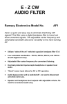
PWM stands for Pulse0
0
Width-Modulation (not
Pretty-Wild-Muscles). In
our case this means that
we change the amount of
1
1
time the IR LED is turned
on versus off in accordance with the data we
0Sec
1Sec 0Sec
1Sec
want to send. For examIR Detector
IR Remote
ple, let’s say we’re sendOutput
Output
ing data at a rate of 1 bit
per second (bps). Each bit would take one second to send. To represent a
logical one, the LED must be switched on and off at a rate of 38 kHz for 60%
RR1 • 5
of the one second time frame (0.60 seconds total of the entire second). For a
logical zero, the LED will still be switched on and off at a rate of 38 kHz, but
this time only for 30% of the total time (0.30 seconds total of the entire second).
When the IR detector “sees” a 38 kHz IR signal, the output of the detector
goes low (it is inverted). Conversely when there is no 38 kHz carrier signal
present, the output idles high. If you were to look at the output of the IR detector you wouldn’t see the original 38 kHz carrier present, just the logical data
that the PWM 38 kHz represents from your IR remote control. If we want to resend this data, we have to modulate a 38 kHz carrier again in accordance with
the data the IR detector puts out. There are a number of different ways we
could do this. One possibility is to turn a 38 kHz oscillator on and off using the
IR detector output as the switch, this lends itself to the problem of how fast our
oscillator can start up and settle however. A better idea is to go one step further and use a micro-controller to generate the 38 kHz carrier. The data output
from the IR detector can be sampled by the micro-controller which in-turn generates a 38 kHz carrier signal that is Pulse Width Modulated (PWM) according
to the detected data.
By using this method with a micro-controller, we can add some intelligence
to the regenerated signal as well. The sample IR remotes we have looked at
send their data at a rate of around 2400 bits per second. This means that our
minimum pulse length for a zero should be 1/2400 x 0.30 seconds long (125
uS). Consider this example, let’s say that the signal from the IR remote is
weak and it fades out due to interference from some other IR source before
the data pulse is finished (i.e. 80 uS instead of 125 uS). The micro-controller
will continue to send the 38 kHz until 125 uS is up, not allowing the retransmitted signal to drop out the way the original source did. This error correction feature can be disabled in case you have a strange remote that is not
compatible (to this point we have yet to run across one that doesn’t work). Remove the jumper from J2 to disable this feature and have U1 blindly re-create
the data it sees.
Once the micro-controller has re-generated your 38 kHz carrier (modulated
by the data), we buffer its output with transistor Q1 to drive the IR LED. The
current through the IR LED is limited by R1 and is typically around 50 mA.
This is pretty hard for an LED but don’t worry. Even though the steady ‘on’
state of a typical IR LED can only handle about 20 mA, we are switching the
LED on and off at 38 kHz during the entire send sequence. The LED may be
on only about 50% of the total time to send the data. To achieve the maximum
transmission range and peak performance from the system, we’ve cranked up
the current a bit to get More Power!!!!
RR1 • 6
RAMSEY “LEARN-AS-YOU-BUILD” ASSEMBLY STRATEGY
Be sure to read through all of the steps and check the boxes as you go to be
sure you didn't miss any important ones. Although you may be in a hurry to see
the end results, before you switch on the power be sure to check all wiring and
components (especially capacitors) for proper orientation. Also check the board
for any possible solder shorts and/or cold solder joints. All of these mistakes
could have detrimental effects on your kit - not to mention your ego!
Kit building tips:
Use a good soldering technique - let your soldering iron tip gently heat the
traces to which you are soldering, heating both wires and pads simultaneously.
Apply the solder on the iron and the pad when the pad is hot enough to melt the
solder. The finished joint should look like a drop of water on paper, somewhat
soaked in.
Mount all electrical parts on the top side of the provided circuit board. The top
side is silk screened with the part number reference designators for easy
positing of the components. When a part is installed, it should be placed flat to
the board with the leads slightly bent on the backside of the board to prevent it
from falling out before soldering in position (1). The part is then soldered
securely to the board (2-4) and the remaining lead length is then clipped off (5).
Notice how the solder joint looks on close up, clean and smooth with no holes
or sharp points (6).
RR1 • 7
This project will not work as well as you may wish if you just slap it together
without following good assembly techniques and all of the instructions. No
matter how clear we may think our manual is, if you have any questions give us
a call at the factory instead of jumping to conclusions. We will be happy to help
you with any problems may run into.
It is always good practice to mount the parts AS LOW AS POSSIBLE to the
board. A 1/4” lead length on a resistor not mounted close to the board can act
as an inductor or an antenna, causing all sorts of problems in your circuit. Be
aware though that there are stand up components in your circuit. They don’t
need to be squished to the board, but keep the portion of the resistor closest to
the board mounted right on the board.
For each part, our word "Install" always means these steps:
1. Pick the correct part value to start with.
2. Insert it into the correct PC board location, making sure the part is
mounted flush to the PC board unless otherwise noted.
3. Orient it correctly, follow the PC board drawing and the written directions
for all parts - especially when there's a right way and a wrong way to solder
it in. (Diode bands, electrolytic capacitor polarity, transistor shapes, dotted
or notched ends of IC's, and so forth.)
4. Solder all connections unless directed otherwise. Use enough heat and
solder flow for clean, shiny, completed connections.
Keeping this in mind, let’s begin by sorting out our components and crosschecking them against the parts list to make sure we have received everything.
NOTE TO NEWCOMERS: If you are a first time kit builder you may find this
manual easier to understand than you may have expected. Each part in the kit
is checked off as you go, while a detailed description of each part is given. If
you follow each step in the manual in order and practice good soldering / kit
building skills, the kit is next to fail-safe. If a problem does occur, the manual
will lead you through step by step in the troubleshooting guide until you find the
problem and are able to correct it.
RR1 • 8
PARTS SUPPLIED WITH YOUR RR1 KIT
Capacitors
3 0.1 uF ceramic capacitors (marked .1 or 104 or 100 nF) [C2,3,4]
2 10 uF electrolytic capacitors [C1,5]
1 1000 uF electrolytic capacitor [C6]
Resistors
1 1K ohm resistor (brown-black-red) [R2]
1 100 ohm resistor (brown-black-brown) [R1]
1 220 ohm resistor (red-red-brown) [R3]
Semiconductors
1 1N4000 series Rectifier Diode (Black body with white stripe marked
1N4001 through 1N4007) [D2]
1 2N3904 NPN transistor (Marked 2N3904) [Q1]
1 78L05 5V Voltage Regulator (Marked 78L05 in a TO-92 transistor style
package) [VR1]
1 Large Green LED [D1]
1 Clear IR LED [D3]
Miscellaneous Components
1 Pre-Programmed 12C509 8-pin PIC micro-controller (Marked with a
sticker labeled RR) [U1]
1 IR Sensor Module [U2]
1 DPDT push button power switch [S1]
1 2.1 mm Power Jack [J3]
1 2-hole screw terminal, .157 green jack [J1]
1 2-pin header [J2]
1 2-pin header option jumper
8 feet of #24 two conductor hook-up wire for IR LED extension cable
1 1/8” diameter x 1” long heat shrink tubing for IR LED assembly
1 1/4” diameter x 1” heat shrink tubing for IR LED assembly
RR1 • 9
RR1 REMOTE REPEATER KIT ASSEMBLY
Assembly of the RR1 is straight forward but it does require some time and
patience. To get our bearings, we will start with mounting the power jack and
move on from there. It serves as a good reference point for the other parts.
1. Install J3, the 2.1 mm power jack. Be sure to get a good, solid
connection to all three pads as this will have to take some mechanical
strain during normal use. Use ample solder without going overboard.
2. Install J1, the 2-screw terminal connector. Make sure and mount it so
the holes are facing the outside edge of the board. This is where you will
be mounting the IR LED wires when you are finished with the rest of the
assembly. The screw terminal makes it easy to work with later so you can
change the IR LED feed wires without using a soldering iron.
3. Install R1, a 100 ohm resistor (brown-black-brown).
4. Install Q1, the 2N3904 transistor. Do NOT mix this up with the 78L05!
Even though these are in the same package style, the inside circuitry is
quite a bit different. Mount this part so the flat side is in the same
orientation as shown on the silk screen.
5. Install C1, a 10 uF electrolytic capacitor. Why do we mention the
capacitor type? It’s because electrolytic capacitors are polarity sensitive;
they only like to be installed in a single orientation. We indicate the
positive side on the PC board with a + sign. The capacitor however is
usually marked on the negative side with a - sign. Make sure and align
them so the negative side is opposite of the positive side we indicate!
6. Install C2, a 0.1 uF ceramic capacitor (marked .1 or 104 or 100 nF).
Ceramic capacitors are not polarity sensitive so whatever direction you
feel like putting it in is fine as long as you use the correct two holes.
7. Install R2, a 1K ohm resistor (brown-black-red).
8. Install the 8-pin DIP Socket used to mount U1 (the PIC micro-controller
IC). It doesn’t matter which way the socket is oriented, as long as the IC
chip is inserted correctly in relation to the silk screen on the circuit board.
You can bend two of the corner leads out slightly to hold the socket in
place when you flip the board over to solder it in. Be sure to solder all
eight pins!
9. Insert U1 (the 8-pin micro-controller) into the socket. Make sure the
notch or dimple which indicates pin 1 on the IC is oriented in the same
direction as the notch indication shown on the silk screen. Before you
push it down into the socket, check to be sure that none of the pins are
bent under or outside of the socket. When you are sure the pins are where
they belong, press it down so that it is seated flat within the socket.
RR1 • 10
10. Install J2, the 2-pin header. It is a tight fit so make sure the pins are
through the holes before trying to solder them.
11. Install C4, a 0.1 uF ceramic capacitor (marked .1 or 104 or 100 nF).
12. Install R3, a 220 ohm resistor (red-red-brown).
13. Install C5, a 10 uF electrolytic capacitor. Again check orientation before
soldering into place.
14. Install VR1, the 78L05 voltage regulator. Make sure the flat side of this
component is orientated the same direction as shown on the silk screen.
This part works by “smoothing” out any junk that may reside on the nonregulated input side of the part. It also allows you to run this kit from a wide
range of supply voltages on the input, while it keeps the output to 5V.
15. Install C6, the large 1000 uF electrolytic capacitor. Double check the
orientation before soldering as this is especially critical with this component.
16. Install D2, a 1N4002 regulator diode. This diode helps to convert AC
from a “wall wart” AC transformer to pulsed DC. C6 accumulates the pulsed
DC and smoothes it out a bit. VR1 then smoothes it out the rest of the way
to make for a nice, clean power source. Make sure the line which indicates
the cathode is installed in the same orientation as shown on the silk screen.
17. Install C3, a 0.1 uF ceramic capacitor (marked .1 or 104 or 100 nF).
18. Install U2, the IR detector IC. Make sure and mount it as shown and
that you solder the mechanical mounting pins as well as the electrical pins.
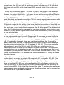
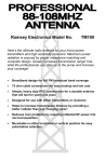
19. Install D1 (the Green LED).
A
This LED will blink whenever the
K
IR detector sees data and begins
to retransmit it. Since D1 is a diode it only works in one direction; watch
your orientation. Notice on the diagram above that the long leg of the LED
indicates the Anode (A) while the shorter one shows the Cathode (K). The
Cathode is the larger fat base that you may see inside of the LED case.
Another common indicator to show the Cathode lead is the flat side of the
LED body itself. Match this up with the circuit board silk screen, the flat side
of the layout symbol on the board. When you solder D1 in place, don’t
mount the LED flush to the board. Leave about 3/4” of lead off of the board
so that the LED element stands in the air. It will eventually be bent over to
peek out of the front of a case giving us a real ‘Pro’ look when finished.
20. Install S1, the power switch. Solder only one pin until you are sure the
switch is flush to the board. If it is cocked at an angle it will not lineup with
the case panel properly.
RR1 • 11
Wow that was fast! 20 steps for something as neat as this may not seem like
a lot, but we are almost done building the kit!
Take a moment to go back through the steps you’ve completed and check
the orientation of all the installed devices before plugging in the power. This
will help you to avoid damaging any critical components by accident when you
fire-it-up the first time (note: we are trying to avoid the “fire” in fire-it-up). Make
sure to check all the capacitors for proper orientation, the micro-controller IC,
as well as the rectifier diode and VR1.
21. The IR LED wiring offers you a bit of flexibility to custom match the
RR1 to your application. You will need to determine how long of a wire
you will actually need to fit the job at hand and then cut it to length. The 8
foot piece of wire that is supplied with the kit is more than enough for most
of the common component cases available today (we didn’t want to
include an entire 1000 foot spool with every kit either!). Leaving the wire
length at 8 feet, even if you only need 4, may be a good idea. Take any
extra wire and neatly coil it into a loop. You never know when someone
will get the urge to re-arrange and you’ll need to extend the wire.
22. Trim both the red and black hook-up wires on each end to 1/4”. Tin all
four ends with solder to prevent them from fraying.
23. Cut the 1/8” piece of heatshrink in half and slide a piece onto one end
of the red wire. On the same end, slide the other piece onto the black
wire. These will keep the leads of the IR LED from shorting together later.
24. Bend the leads of the IR LED outward in a slight ’Y’ formation to give
yourself some space between the two leads to solder the hook-up wires.
25. Attach the IR LED to the hook-up wire by soldering the black wire to
the Cathode (K) and the RED wire to the Anode (A). Use the end with the
1/8” heat shrink tubing in place so you can slide them over the junctions
later. Look at the LED diagram of D1 for clarification if needed. A pair of
needle-nose pliers work well to make small loops in the wire ends to slide
the IR LED leads through. After you slide the leads through the loops,
tighten them down so the IR LED leads are held in place for soldering.
26. Trim back the excess IR LED lead wire for a nice, clean assembly and
slide the heat shrink tubing up and over the leads to the base of the IR
LED. You may need to trim any sharp edges off of the solder joint before
the tubing will slip over.
27. Install the other end of the Black wire into the J1 terminal jack closest
to the corner (labeled BLACK) and the Red wire into the other hole
(labeled RED). Use a small screwdriver to gently tighten the down screws.
FINISHED!!! Now we are ready to begin testing our handiwork!
RR1 • 12
TESTING THE RR1
To begin testing the RR1 we will need the following items:
AC power supply (6 to 12VAC) or DC power supply (8 to 14VDC).
A known functional IR remote control.
A mating piece of equipment that the remote control works with.
Begin by positioning the IR LED in front of the equipment you intend to control. To hold the IR LED in place, try using a piece of electrical tape. It works
well for testing and it normally doesn’t leave any residue on your valuable toys
when you take it off! Otherwise mount it into position where you will be using it
from now on and we’ll go for broke. Note the LED lens works much like a
flashlight and is fairly directional. If you need a broad distribution of IR light, a
piece of wax paper over the lens will diffuse the IR LED to cover a broader
area. This is a poor man’s frensel lens!
Make sure the RR1 is powered off. Use your body to block the normal path
of your remote control to the equipment and verify that you cannot activate
components. Sometimes the walls near you will reflect enough IR for the
equipment to detect so it would be hard to verify if the RR1 is working. Now
turn on the RR1 and press some remote control buttons. You should see the
green LED on the RR1 flash with the remote signal while at the same time the
equipment under control follows your every command!
Now that you know the unit is working, let’s finish the job by permanently
shrinking the protective tubing over the leads of the IR LED for added structural support.
28. Use a heat gun on a low heat setting (or a hair drier) to carefully shrink
the 1/8” tubing to size over the leads of the IR LED. A soldering iron may
also be used to shrink the tubing by holding it close to the tubes, make
sure you don’t directly contact the tubing however. These will keep the
leads of the IR LED from shorting together.
29. Now slide the larger 1/4” tubing over the rear leaded end of the IR
LED for added support. The clear IR LED body should stick out of the tubing by about 3/8” or so. The tubing will reduce the stress on the IR LED
lead wires when it is shrunk around with the smaller 1/8” pieces.
30. Use the heat gun again on a low heat setting (or a hair drier) to carefully shrink the larger tubing to size. It should shrink fairly tightly over the
whole assembly.
There really isn’t much more to it than that so let’s start using the RR1!
RR1 • 13
USING THE RR1
The beautiful thing about it is that there really is no secret to using the RR1.
The only option you may need to change is the jumper configuration of J2, the
‘Data Restore’ enable header. By default, leave the jumper header ’IN’ or on
the pins. This will tell the micro-controller to automatically correct any errant IR
data that is received. Should you have trouble with some remotes, simply remove the jumper for straight through operation.
We thought this might be a good spot for some mounting ideas that may
help with the usage of your RR1. Primarily you will want to put the RR1 in a
discrete location that isn’t too obtrusive. It should be where you can easily
point your remote control’s IR data in a fashion that is unimpeded by other objects. One idea would be behind the speaker grill (if it isn’t completely opaque
to IR) or under the coffee table. In my case, I found it would still work when
positioned behind the curtains on the window sill (the IR detector was that
sensitive). Now I can beam the remote control in the logical direction of the TV
screen instead of behind the couch!
The real trick is how to get the IR emitting LED mounted so that all of your
components can see it. The optimum way would be to use a coat hanger to
suspend the LED out in front of the components and have it shine back at
them. Unfortunately this is quite ugly and could poke out too far to be able to
close the doors of a cabinet. If it will be inside of a cabinet, you can conveniently bounce the light off of some small pieces of aluminum foil mounted to
the back sides of the doors and reflect the IR down to the components. With a
little work, you could even permanently mount the IR LED on the inside of one
of the doors. This configuration might take a bit of wire however in order to
discreetly snake the hook-up from the RR1 receiver down through the cabinet
and along the door. So far the longest piece of wire we’ve tried was about 750
feet… no problem!! You will probably find the output of the IR LED is intense
enough that it will probably activate all of your components just by reflecting
around inside of the cabinet.
If you do not have doors to reflect the IR signal from the RR1 emitter, angling the light from above somewhere will work well also. In my case my components are currently sitting on a coffee table behind the couch until we save
enough pennies to buy a cabinet. In this case I can actually mount the IR LED
in a crack in the couch to aim it at the components. This worked out quite well
for me since the IR LED is now all but hidden from view. Hopefully it doesn’t
get yanked out the next time I’m scrambling through the cushions for change
to tip the pizza delivery guy!
RR1 • 14
TROUBLESHOOTING GUIDE
PROBLEM: The green LED doesn’t light up when I aim my remote at it.
SOLUTION: There are a few things that can go wrong here so we will go
through the possibilities in order of there likelihood:
1. You forgot to turn on the power, or your DC adapter isn’t compatible (the
polarity is reversed).
2. You installed the green LED in backwards. Please check the orientation.
We’ve all done it at one time or another!
3. The battery in your remote control is shot. Replace the battery and re-try.
4. It is an ancient remote that has a hammer and chimes inside. Those just
won’t work, this is for IR remotes only.
5. You are trying to relay an IR remote that is modulated at some other frequency than 38 kHz. There are a variety of ranges available, but 38 kHz is
by far the most common. Most consumer components operate at 38 kHz.
The RR1 ONLY works 38 kHz carrier signal remotes.
PROBLEM: The LED lights, but the IR LED seems to have no effect.
SOLUTION: Try swapping the wires on the screw terminal. Either you wired
the IR LED backwards or there is a poor contact. Check the hook-up wire connection on the IR LED end as well, it may be broken or poorly soldered.
PROBLEM: The LED stays constantly lit.
SOLUTION: You have the detector to near to the IR LED. The IR LED will
transmit back to the detector causing the detector to lock on in a feedback
loop. Reposition the IR LED to aim away from the detector or even use some
creative taping to shield one from the other.
PROBLEM: I just can’t make the darn thing work!
SOLUTION: Call Ramsey Support at 1-585-924-4560 and look at the warranty
information at the end of this manual. We are here to help you and we’ll try to
reduce your frustration as much as possible right over the phone. It usually is
something simple. Oh, please count to ten before calling and take a few deep
breaths as well… we like to think happy thoughts in the Tech. Dept. so positive phone calls keep us continuing on the path to ‘Zen’.
RR1 • 15
RR1 • 16
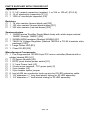
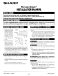
RR1 PARTS PLACEMENT DIAGRAM
RR1 • 17
RR1 SPECIFICATIONS:
There are only a few specifications that need to be documented for this particular product. Please note that these are subject to change.
Power Supply:
•
•
•
AC power supply = 6 to 12 VAC @ 100 mA
or
DC power supply = 8 to 16 VDC @ 100 mA (Positive tip plug)
Current draw with a 12VDC source averages:
⇒ 7 mA Standby Mode
⇒ 16 mA Active IR Data Re-transmitting
Dimensions:
• PCB size: 4.0” x 4.7”
• Max component height: 7/8”
Miscellaneous:
•
•
•
•
Works with any standard 38 kHz carrier IR remote.
Max effective BAUD rate: 2400 bps – standard for remotes.
IR receiver module has an effective pick-up range of 11 meters (36 feet!).
Max IR LED (D3) wire extension length: Unknown!! Tested over 750 feet
and still going!
RR1 • 18
The Ramsey Kit Warranty
Please read carefully BEFORE calling or writing in about your kit. Most problems can be
solved without contacting the factory.
Notice that this is not a "fine print" warranty. We want you to understand your rights and ours too!
All Ramsey kits will work if assembled properly. The very fact that your kit includes this new manual
is your assurance that a team of knowledgeable people have field-tested several "copies" of this kit
straight from the Ramsey Inventory. If you need help, please read through your manual carefully.
All information required to properly build and test your kit is contained within the pages!
1. DEFECTIVE PARTS: It's always easy to blame a part for a problem in your kit, Before you
conclude that a part may be bad, thoroughly check your work. Today's semiconductors and passive
components have reached incredibly high reliability levels, and it’s sad to say that our human
construction skills have not! But on rare occasions a sour component can slip through. All our kit
parts carry the Ramsey Electronics Warranty that they are free from defects for a full ninety (90)
days from the date of purchase. Defective parts will be replaced promptly at our expense. If you
suspect any part to be defective, please mail it to our factory for testing and replacement. Please
send only the defective part(s), not the entire kit. The part(s) MUST be returned to us in suitable
condition for testing. Please be aware that testing can usually determine if the part was truly
defective or damaged by assembly or usage. Don't be afraid of telling us that you 'blew-it', we're all
human and in most cases, replacement parts are very reasonably priced.
2. MISSING PARTS: Before assuming a part value is incorrect, check the parts listing carefully to
see if it is a critical value such as a specific coil or IC, or whether a RANGE of values is suitable
(such as "100 to 500 uF"). Often times, common sense will solve a mysterious missing part
problem. If you're missing five 10K ohm resistors and received five extra 1K resistors, you can
pretty much be assured that the '1K ohm' resistors are actually the 'missing' 10 K parts ("Hum-m-m,
I guess the 'red' band really does look orange!") Ramsey Electronics project kits are packed with
pride in the USA. If you believe we packed an incorrect part or omitted a part clearly indicated in
your assembly manual as supplied with the basic kit by Ramsey, please write or call us with
information on the part you need and proof of kit purchase.
3. FACTORY REPAIR OF ASSEMBLED KITS:
To qualify for Ramsey Electronics factory repair, kits MUST:
1. NOT be assembled with acid core solder or flux.
2. NOT be modified in any manner.
3. BE returned in fully-assembled form, not partially assembled.
4. BE accompanied by the proper repair fee. No repair will be undertaken until we have received
the MINIMUM repair fee (1/2 hour labor) of $25.00, or authorization to charge it to your
credit card account.
5. INCLUDE a description of the problem and legible return address. DO NOT send a separate
letter; include all correspondence with the unit. Please do not include your own hardware
such as non-Ramsey cabinets, knobs, cables, external battery packs and the like. Ramsey
Electronics, Inc., reserves the right to refuse repair on ANY item in which we find excessive
problems or damage due to construction methods. To assist customers in such situations,
Ramsey Electronics, Inc., reserves the right to solve their needs on a case-by-case basis.
The repair is $50.00 per hour, regardless of the cost of the kit. Please understand that our
technicians are not volunteers and that set-up, testing, diagnosis, repair and repacking and
paperwork can take nearly an hour of paid employee time on even a simple kit. Of course, if we find
that a part was defective in manufacture, there will be no charge to repair your kit (But please
realize that our technicians know the difference between a defective part and parts burned out or
damaged through improper use or assembly).
4. REFUNDS: You are given ten (10) days to examine our products. If you are not satisfied, you
may return your unassembled kit with all the parts and instructions and proof of purchase to the
factory for a full refund. The return package should be packed securely. Insurance is
recommended. Please do not cause needless delays, read all information carefully.
RR1 • 19
RR1 REMOTE REPEATER KIT
Quick Reference Page Guide
Introduction ..........................................4
Theory of Operation ..............................5
Parts List ...............................................9
Assembly Instructions .........................10
Testing the RR1 ..................................13
Using your RR1 ...................................14
RR1 Schematic ...................................16
Specifications ......................................18
Warranty ..............................................19
REQUIRED TOOLS
• Soldering Iron Ramsey WLC100
• Thin Rosin Core Solder Ramsey RTS12
• Needle Nose Pliers Ramsey MPP4 or RTS05
• Small Diagonal Cutters Ramsey RTS04
<OR> Technician’s Tool Kit TK405
ADDITIONAL SUGGESTED ITEMS
• Holder for PC Board/Parts Ramsey HH3
• Desoldering Braid Ramsey RTS08
• Digital Multimeter Ramsey M133
Price: $5.00
Ramsey Publication No. MRR1
Assembly and Instruction manual for:
RAMSEY MODEL NO. RR1
RAMSEY ELECTRONICS, INC.
590 Fishers Station Drive
Victor, New York 14564
Phone (585) 924-4560
Fax (585) 924-4555
www.ramseykits.com
TOTAL SOLDER POINTS
54
ESTIMATED ASSEMBLY
TIME
Beginner .............. 1.5 hrs
Intermediate ........ 1.0 hrs
Advanced ............. 0.5 hrs
RR1 • 20