1
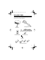
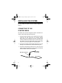
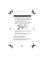
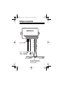
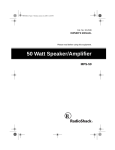
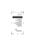
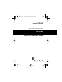
49-851.fm Page 1 Thursday, August 19, 1999 10:56 AM
Cat. No. 49-851
OWNER’S MANUAL
Please read before using this equipment.
TD-1500
Auto Theft Deterrent System
49-851.fm Page 2 Thursday, August 19, 1999 10:56 AM
INTRODUCTION
The TD-1500 Auto Theft Deterrent System is a starter disable
module that helps prevent auto theft or unauthorized vehicle
use. It quickly connects to your vehicle’s ignition system, and
has an easy-to-use remote for arming and disarming. The
armed indicator shows when the system is on, to deter
would-be thieves from attempting to break in.
BEFORE YOU BEGIN
It is important that you know where to find constant power,
vehicle ground, and the starter wire under the dashboard of
your vehicle. To help you find this, we recommend you get
the wire color information from your vehicle’s dealer, in the
vehicle’s service manual, or by calling the Auto Security Helpline at 1-800-598-2527.
You also need the following items:
• 12-volt test light or DC voltmeter
• Wire-piercing probe adapter (such as RadioShack Cat.
No. 278-715)
• Several extra wire tap-in connectors
© 1996 Tandy Corporation.
All Rights Reserved.
RadioShack is a trademark used by Tandy Corporation.
2
49-851.fm Page 3 Thursday, August 19, 1999 10:56 AM
INCLUDED ITEMS
Your TD-1500 includes the following items. Be sure you have
all items before you begin installation.
Wiring Harness
Main System
Status Indicator with Bracket and Harness
Disarm
Two-Button Remote
Double-Sided Tape
Wire Ties
Wire Tap-In Connectors
3
49-851.fm Page 4 Thursday, August 19, 1999 10:56 AM
INSTALLING THE SYSTEM
As you install the system, see the “Wiring Diagram” on
Page 11.
CONNECTING TO THE
STARTER WIRES
The starter wire connects the ignition switch to the starter solenoid. Follow these steps to find this wire.
1. Using the starter solenoid’s color coded wires as a guide,
locate the wire that goes from your vehicle’s ignition
(key) switch to the solenoid. This wire is usually found
under the dashboard where the wires connect to the ignition switch. If you are unsure which is the correct wire,
call the Auto Security Helpline at 1-800-598-2527.
2. Connect the negative (usually black) lead from a 12-volt
test light or DC voltmeter to a metal vehicle body part.
3. Connect a wire-piercing probe (Cat. No. 278-715) to the
positive lead and press the pin tip through the solenoid
wire’s insulation and into the wire itself.
Wire-Piercing Probe
To the Meter
or Test Light
Solenoid Wire
4
49-851.fm Page 5 Thursday, August 19, 1999 10:56 AM
4. Start your vehicle. The test light should light or the meter
should indicate voltage only while the engine is cranking (not while it is stopped or running).
5. If the test fails, contact the Auto Security Helpline at 1800-598-2527 for assistance in finding the correct wire.
6. Turn off the engine. Then cut the wire you located in
Steps 2–4 at a point where there are several inches of
wire on each side of the cut.
Note: If you cut the correct wire, you will not be able to
start your vehicle until you complete installation.
7. Try to start your vehicle. The engine should not crank.
If it does crank, you cut an incorrect wire — use a wire
tap-in to restore the connection.
8. Snap a yellow tap-in’s grooved channel over the wire
going to the back of the ignition switch. Then push the
system’s red/black wire into the other channel.
9. Use pliers to squeeze the metal tap down through the
wires. Then snap the tap-in’s plastic cover closed.
Wire from Switch
Red/Black Wire to System
10. Repeat Steps 8 and 9 for the wire going to the starter
solenoid (the other end of the cut wire) and the system’s
white wire.
11. Use the supplied large wire tie to resecure all loose
wires.
5
49-851.fm Page 6 Thursday, August 19, 1999 10:56 AM
CONNECTING TO POWER
1. Touch the negative lead from a 12-volt test light or DC
voltmeter to a metal part of your vehicle and use the positive lead (with a wire-piercing probe adapter) to probe
for an existing wire that has 12 volts when your vehicle’s
ignition is off.
2. Use one of the supplied wire tap-ins to connect the system’s red wire to the wire you located in Step 1, then
replace the fuse.
3. Connect the system’s black wire to a metal vehicle part,
using an existing bolt or screw.
4. Plug the power harness’ three-pin connector into the
system with the antenna lead to the left (see “Wiring Diagram” on Page 11).
5. Immediately press DISARM on the remote transmitter.
This trains the system to recognize the remote.
INSTALLING THE STATUS INDICATOR
Select a highly visible location for the indicator. You can use
the supplied bracket to stick the indicator on your dashboard
or drill a hole in the dash’s front panel and insert the indicator.
Follow these steps to install it.
1. Plug the indicator’s two-wire connector into the two-wire
jack on the system.
6
49-851.fm Page 7 Thursday, August 19, 1999 10:56 AM
2. If you are using the supplied bracket, clean the
mounting surface with denatured alcohol and allow it to
dry. Peel the backing off of one side of the double-sided
tape and press it onto the bottom of the bracket. Then
peel off the adhesive backing from the other side of the
tape and press the bracket onto the dash.
If you are mounting the indicator in the dash’s front
panel, drill a 5/16-inch hole at the selected location, taking care not to damage anything behind the surface.
Grommet
Indicator
3. Push the supplied snap-in grommet into the mounting
surface’s hole from the front of the mounting surface
(bracket or dash panel).
4. From the back of the mounting surface, push the indicator into the grommet until it snaps into place.
MOUNTING THE SYSTEM
Use the two supplied small wire ties to secure the system under the dash. Secure all loose wires except the yellow antenna wire. Allow the antenna wire to hang down.
7
49-851.fm Page 8 Thursday, August 19, 1999 10:56 AM
USING THE SYSTEM
ACTIVATING THE REMOTE CONTROL
You must train the system to respond to the supplied remote
control. To activate the remote control, immediately after applying power, press DISARM on the remote. The system
beeps twice.
If the system loses power, the system stops responding to
the remote. To reactivate it, simply press DISARM on the remote after power is restored.
Your system can learn two remote codes if you want to add a
second remote control (RadioShack Cat. No. 49-845). To activate a second remote control code, be sure the system is
disarmed, then hold down ARM for 10 seconds. The status
indicator flashes. Press DISARM on the new remote to activate it. The status indicator stops flashing.
ARMING AND DISARMING THE
STARTER
To disable your starter, press ARM on the remote control. The
indicator flashes rapidly. If you try to start your vehicle, the
engine does not crank.
To enable the starter, press DISARM on the remote control.
The indicator turns off. The vehicle now starts as usual.
8
49-851.fm Page 9 Thursday, August 19, 1999 10:56 AM
CARE AND MAINTENANCE
To enjoy your starter kill module for a long time:
• Keep the module dry. If it gets wet, wipe it dry immediately.
• Handle the module gently and carefully. Don’t drop it.
Modifying or tampering with the starter kill module’s internal
components can cause a malfunction and invalidate its warranty. If your starter kill module is not performing as it should,
take it to your local RadioShack store for assistance.
REPLACING THE REMOTE
CONTROL’S BATTERY
If your remote control stops working or if its range is reduced,
replace its battery. Follow these steps to replace the battery.
1. Snap apart the case halves, taking care not to lose any
of the remote control’s pieces.
2. Remove the old battery and replace it with a 12-volt
remote control battery (Cat. No. 23-144).
3. Put all parts back in place and snap the case halves
back together.
If you lose your remote control, you can get a replacement at
your local RadioShack store. The four-button remote (Cat.
No. 49-845) also controls this system — just use the top two
buttons.
9
49-851.fm Page 10 Thursday, August 19, 1999 10:56 AM
SPECIFICATIONS
System Power . . . . . . . . . . . . . . . . . . . . . . . . 9–16 Volts DC
Current Draw . . . . . . . . . . . . . . . . . . . . . . 22 mA (Disarmed)
Pulsed 40 mA (Armed)
Maximum Switched Current . . . . . . . . . . . . . . . . . . 30 Amps
Remote Control Battery . . . . . . . . . . . . . . . . . . . . . . . 12 Volt
Size (HWD) . . . . . . . . . . . . 33/8 × 23/8 × 11/8 Inches (System)
211/16 × 15/16 × 1/2 Inches (Remote)
Weight . . . . . . . . . . . 2.8 ounces (System Without Harness)
0.9 Ounces (Remote)
RF Carrier. . . . . . . . . . . . . . . . . . . . . . . . . . . . . 303.875 MHz
RF Power Output . . . . . . . . . . . . . . . . . . 5,580 µV at 1 Meter
10
49-851.fm Page 11 Thursday, August 19, 1999 10:56 AM
Yellow — Antenna
Red — +12 Volts
Black — Ground
Status
Indicator
Power Harness
Red/Black — To Switch
White — To Starter
WIRING DIAGRAM
To the
Starter Solenoid
To the
Ignition Switch
Cut the wire going from
the Ignition Switch to the
Starter Solenoid.
11
49-851.fm Page 12 Thursday, August 19, 1999 10:56 AM
RadioShack Limited Warranty
This security product is warranted against manufacturing defects in
material and workmanship for ninety (90) days from the date of purchase from RadioShack company owned stores and authorized
RadioShack franchisees and dealers. Within this period RadioShack
will repair the security product without charge for parts and labor.
Simply bring your RadioShack sales slip as proof-of-purchase
date to any RadioShack store.
This warranty does not cover damage or failure caused by or attributable to Acts of God, abuse, misuse, improper or abnormal usage,
faulty installation, improper maintenance, lightning or other incidence
of excess voltage, or any repairs other than those provided by a
RadioShack Authorized Service Facility, or transportation costs.
RadioShack is not responsible or liable for indirect, special, or
consequential damages arising out of or in connection with the
use or performance of the product or other damages with
respect to loss of property, loss of revenues or profit, or costs
of removal, installation or reinstallation.
EXCEPT AS PROVIDED HEREIN, RadioShack MAKES NO
EXPRESS WARRANTIES AND ANY IMPLIED WARRANTIES ARE
LIMITED IN DURATION TO THE DURATION OF THE WRITTEN
LIMITED WARRANTIES CONTAINED HEREIN. Some states do not
allow the limitation or exclusion of incidental or consequential damages and some states do not allow limitation or exclusion of implied
warranties; therefore, the aforesaid limitation(s) or exclusion(s) may
not apply to the purchaser. There will be charges rendered for
repairs to the product made after the expiration of the aforesaid
ninety (90) day warranty period.
This warranty gives you specific legal rights and you may have other rights
which vary from state to state.
We Service What We Sell
10/95
RadioShack
A Division of Tandy Corporation
Fort Worth, Texas 76102
10/96
Printed in the USA