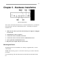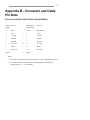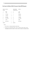
1
BR-ASI01
BR-ASX01
Data Comm for Business, Inc.
807 Pioneer Street
Champaign, IL 61820
217-352-3207
Rev. Date: October 17, 1996
This manual applies to both the “I” and “X” router models. The “I” model
(BR-ASI01) is single protocol TCP/IP only. The “X” model (BR-ASX01) is a
multi-protocol router that routes TCP/IP, IPX, DECnet, and Appletalk.
When using this manual with “I” model router, ignore the manual sections
pertaining to protocols other than TCP/IP.
CHAPTER 1 - INTRODUCTION
ABOUT THE BR ROUTER
Getting Started
Hardware Installation
RouterView Software Installation
Command Line Preparation
Quickstart Configuration
Appendices and Index
7
7
7
7
8
8
8
8
CHAPTER 2 - GETTING STARTED
A FEW NOTES
Please Read The Manuals
Warranty and Service
Getting Help With the BR Router
WHAT YOU WILL NEED TO GET STARTED
Supplied with the BR Router
Needed For Installation
Ethernet Connection Requirements
Thick Ethernet
Thin Ethernet
10Base-T Twisted-Pair Ethernet
Telco Line Connection Requirements
RS-232 Port
9
9
9
9
9
9
9
10
10
10
10
10
11
11
CHAPTER 3 - HARDWARE INSTALLATION
Mounting the Router
Connecting the Router to the Ethernet
Connecting to Thick Ethernet
Connecting to Thin Ethernet
Connecting to Twisted-Pair Ethernet
Connecting a Line Device to the BR Router
Connecting Devices to the RS-232C Port
Connecting an Out-of-Band Management Console
Powering Up the Router
13
13
14
14
14
14
14
15
15
15
CHAPTER 4 - ROUTERVIEW SOFTWARE INSTALLATION
RouterView for Windows
System Requirements
Installing and Running RouterView for Windows
RouterView for Macintosh
System Requirements
Installing and Running RouterView for Macintosh
17
17
17
18
18
18
CHAPTER 5 - SETTING UP COMMAND LINE MANAGEMENT
Out-of-Band Command-Line Management
Setting Up Telnet Operation
* Available on “X” model router only.
21
21
21
CHAPTER 6 - QUICKSTART INSTRUCTIONS
ETHERNET PORT CONFIGURATION
IP Protocol
Required for IP
Suggested for IP
* IPX Protocol
Required for IPX
Suggested for IPX
* AppleTalk Protocol
Required for AppleTalk
Suggested for AppleTalk
* DECnet Protocol
Required for DECnet
Suggested for DECnet
WAN PORT PPP CONFIGURATION
Operating Software
Required for PPP
IP Protocol
Required for IP
Suggested for IP
* IPX Protocol
Required for IPX
Suggested for IPX
17
23
23
24
24
24
24
24
24
25
25
25
25
25
25
25
26
26
26
26
26
27
27
27
* AppleTalk Protocol
Required for AppleTalk
Suggested for AppleTalk
* DECnet Protocol
Required for DECnet
Link Configuration
Required for Dedicated/Leased Line Operation
Suggested for Dedicated/Leased Line Operation
Required for Dial-On-Demand Operation
Suggested for Dial-On-Demand Operation
Physical Comm Settings
WAN PORT FRAME RELAY CONFIGURATION
Operating Software
Required for Frame Relay
IP Protocol
Required for IP
Suggested for IP
* IPX Protocol
Required for IPX
Suggested for IPX
* AppleTalk Protocol
Required for AppleTalk
Suggested for AppleTalk
* DECnet Protocol
Required for DECnet
Link Configuration
Suggested for Dedicated/Leased Line Operation
Frame Relay DLCI Mappings
Physical Comm Settings
* Available on “X” model router only.
27
27
27
27
27
28
28
28
28
28
29
29
29
29
30
30
30
30
30
31
31
31
31
31
31
31
32
32
32
APPENDIX A - SHIPPING DEFAULTS
Ethernet Port
IP Defaults
* IPX Defaults
* AppleTalk Defaults
* DECnet Defaults
WAN Port
IP Defaults
* IPX Defaults
* AppleTalk Defaults
* DECnet Defaults
Link & Physical Defaults
33
33
33
33
33
33
33
33
33
34
34
34
APPENDIX B - CONNECTOR AND CABLE PIN OUTS
35
Pin Outs for DIN-8 to RS-232 Data Cable (DCE/Male)
35
Pin Outs for DIN-8 to RS-232 Console Cable (DTE/Female) 36
APPENDIX C - LIGHT PATTERNS AND TEST SWITCH SETTINGS 37
BR Router Light Patterns
Traffic Indicators
Other Indicators
Level 1 Panic Indicators
BR Router Switch Settings
* Available on “X” model router only.
37
37
37
37
37
7
Chapter 1 - Introduction
About the BR Router
Congratulations on your purchase of the BR Router Ethernet to wide area router.
The BR Router supports the IP, IPX, AppleTalk, and DECnet protocols, with dialon-demand or dedicated line operation over voice, leased/switched, or ISDN lines,
using the PPP and/or the Frame Relay wide area protocols.
This manual will help you install the BR Router to connect your local Ethernet to a
wide area network. The wide area network may be connected to other DCB routers,
or to routers from other vendors. You can also use the BR Router to connect your
network to an Internet Service Provider.
In short, the installation steps are:
1.
Install the BR Router hardware and connect it to a line communication device
(including a modem, CSU/DSU, or ISDN Terminal Adapter).
2.
Select the management method you wish to use with the router. If you want to
use the RouterView management software, you must install the software on a
Windows PC or Macintosh computer which is connected to your network.
3.
Configure the BR Router LAN and WAN parameters using the management
method you have chosen.
If you have any difficulties during the installation or use of the BR Router that are
not answered by this guide, please call DCB or your BR Router reseller. DCB’s
phone number is listed on the front of this guide. We will be happy to help you.
The manual is divided into several sections that should provide you with all the
information you will need to use the BR Router on your network.
Getting Started
This part of the manual describes the contents of the BR Router package and
emphasizes the preparation and equipment you will need to install the router.
Hardware Installation
Here you will find step-by-step instructions on how to physically install the BR
Router and connect it to your local Ethernet and your wide area network.
Instructions are included for thick, thin, and twisted-pair Ethernet environments as
well as modems, CSU/DSUs, and ISDN terminal adapters.
8
RouterView Software Installation
If you plan to use RouterView, DCB’ GUI (Graphical User Interface) management
software which is included with your router, then read this section. Instructions are
provided on how to install RouterView for Windows or Macintosh environments.
Command Line Preparation
If you have decided to use command line management, either out-of-band (through
the AUX port), or in-band through Telnet, read this section.
Quickstart Configuration
The Quickstart section provides a list of parameters that must be entered into a
router for proper operation.
Appendices and Index
Additional information that might be of interest to you such as technical
specifications and a quick reference to specific information can be found at the end
of this guide.
9
Chapter 2 - Getting Started
A Few Notes
Please Read The Manuals
The manuals included with your BR Router contain some very important
information about the BR Router and local and wide area networking in general.
Please read this manual thoroughly, and refer to the management reference guides
as required. It’s worth the few minutes it will take.
Also, please fill out the warranty registration card and return it to us today. This
will help us keep you informed of updates to the BR Router and future products
available from DCB.
Warranty and Service
The BR Router is covered by the DCB Integrated Support Package, which includes
a one year comprehensive warranty, a twenty-four hour advanced replacement
program, unlimited phone support, and software upgrades for the life of the product.
Getting Help With the BR Router
If you have a question about the BR Router and can’t find the answer in this
manual, feel free to call our technical support department at (217) 352-3207. You
may also send support questions via e-mail to [email protected].
What You Will Need To Get Started
Before connecting the BR Router, please check the list below to make sure that you
have received all of the items that are supplied with the BR Router package.
You should also make sure you have any additional items that are necessary to
connect the router to your network.
Supplied with the BR Router
Please check your shipping package for the following items:
•
BR Router unit
•
Power supply
•
One DIN-8 to DB-25 data cable
•
One DIN-8 to DB-25 auxiliary port cable
•
Windows RouterView diskette
10
•
Macintosh RouterView diskette
•
Windows download software diskette
•
Macintosh download software diskette
•
RouterView reference guide
•
Command line reference guide
•
Warranty registration card
v Note: Some routers may be shipped with two RS-232 “Y” cables. These cables
can be used for both data and auxiliary port operation.
Needed For Installation
Before connecting the BR Router to your network, you need to make sure that you
have the necessary equipment for connecting to the local Ethernet and the wide area
transmission device(s) (modem, CSU/DSU, ISDN terminal adapter).
Ethernet Connection Requirements
The BR Router’s Ethernet port directly supports thick, thin and 10BaseT twistedpair Ethernet. Switching among the three ports is automatic – simply plug the
proper Ethernet connector into its port. Other Ethernet cabling types (such as fiber
optic cabling or pre-10BaseT twisted-pair) can be supported using adapters which
connect to a thick Ethernet port.
Thick Ethernet
To connect the router’s Ethernet port to a standard (thick) Ethernet cable you will
need a transceiver cable connection at the correct location on your Ethernet cable.
The transceiver cable will attach directly to the DB-15 connector on the router.
Thin Ethernet
To connect the router’s Ethernet port to a thin Ethernet cable you will need a Tconnector installed at the correct location on your Ethernet cable. A T-connector is
required for proper termination of the cable.
10Base-T Twisted-Pair Ethernet
To connect the router’s Ethernet port to twisted-pair Ethernet cabling you will need
an unshielded twisted-pair wire that is connected to a 10BaseT-compatible twistedpair hub.
v Note: Ethernet cables and cable connectors are not supplied with the BR Router
product. Please contact your reseller or your DCB representative for information
on obtaining the correct Ethernet cabling supplies.
11
v Note: These hardware installation instructions assume that your Ethernet cabling
is already in place. Thin coaxial Ethernet network cabling should be terminated at
each end with 50 Ohm terminator plugs. A T-connector or transceiver must be
available in the location where you will be installing the router.
Telco Line Connection Requirements
The BR Router is not a line communications device. In order to connect to a wide
area transmission line, you must use a modem, CSU/DSU, or ISDN Terminal
Adapter. Which of these devices you use depends on the type of wide area line to
which you are connecting.
v Note: Before attempting to connect the BR Router to a leased telco line, use the
loopback features of your CSU/DSU’s to check the line. This can save you a
considerable amount of time, since the more equipment you have on the line, the
more difficult it becomes to determine where a problem is occurring.
RS-232 Port
No matter which type of wide are line you plan to connect to, the line
communications device you use must provide an RS-232 connection in order to be
used with the BR Router.
The BR Router includes one DIN-8 to DB-25 RS-232 sync/async data cable. This
cable supports RS-232 asynchronous modems, synchronous leased and switchedCSU/DSU’s, and North American ISDN Terminal Adapters.
Some Japanese and European terminal adapters may require an adapter plug. For
more information, contact DCB.
v Note: Please use only this cable when connecting your line communication
device to the BR Router. The cables provided with other equipment do not provide
all of the connections required between connector pins for correct hardware
handshaking and synchronous clocking.
13
Chapter 3 - Hardware Installation
BR Router Back Panel
This section of the manual describes how to connect the BR Router to your Ethernet
network and your wide area communications device. In summary, the steps for
installation are:
1.
Make sure the router is powered down and the power supply is not plugged
in to the wall.
2.
Wall mount the router, if required.
3.
Connect the router to the Ethernet network.
4.
Connect the router to the wide area line communications device.
5.
Power up the line communications device.
6. Plug in the power supply and power up the router.
Mounting the Router
The BR Router can be left standalone on a desktop or equipment table, or can be
wall mounted.
v Note: Wall mounting requires a wall-mount bracket kit (part number A00-0987)
from DCB.
For wall mounting, follow the instructions included with the wall-mount bracket
kit.
14
Connecting the Router to the Ethernet
For thick and thin Ethernet networks you should have installed your Ethernet
cabling before you install the BR Router.
If you have a coax installation, the Ethernet network cable should be terminated at
both ends with 50 Ohm network terminating resistors, and a T-connector or
transceiver should be available at the location where you will connect the router.
If you are installing a twisted-pair connection, and the twisted-pair hub is already in
place, or a T-connector or thicknet transceiver is already installed on your Ethernet
cable, you can connect the router to an active network without interrupting network
activity.
The BR Router’s Ethernet interface features all three media connector types. The
active media connection will automatically be selected when you attach a cable.
Do not terminate inactive connectors on the router, as this may cause an
incorrect media type to be selected.
Connecting to Thick Ethernet
To connect the router to a thick Ethernet network, simply plug one end of a
transceiver cable into the DB-15 transceiver connector located on the back panel of
the unit. Then, plug the other end of the transceiver cable into the transceiver
which should already be attached to the thick Ethernet cable.
Connecting to Thin Ethernet
In order to connect the router to a thin Ethernet cable, connect a T-connector to the
BNC connector located on the rear panel of the unit.
Connecting to Twisted-Pair Ethernet
Before connecting the router to twisted-pair cabling you need an unshielded twistedpair cable that is already connected to your 10BaseT-compatible twisted-pair hub.
To connect the router to the twisted-pair network, simply plug the twisted-pair cable
into the RJ-45 connector on the back of the unit.
Connecting a Line Device to the BR Router
The BR Router supports high-speed synchronous or asynchronous operation over
one RS-232 connector.
The BR Router supports both PPP and Frame Relay link protocols on this WAN
port.
Connecting Devices to the RS-232C Port
This port -- marked WAN -- can be used to connect to synchronous or asynchronous
line communications devices at rates up to 128Kbps (115.2 Kbps async).
15
Examples include modems, leased or switched CSU/DSU’s, and ISDN terminal
adapters.
You may select either dial-on demand, redial if down (“always up” mode), or leased
line operation. These ports may also be set to receive ISDN or switched-56
incoming calls.
To connect a device, first make sure that both units are powered off. Then, simply
connect one of the supplied RS-232 data cables (not an auxiliary port cable)
between the router and the device.
v Note: The BR Router RS-232 port requires that your line communications device
be set to supply the RS-232 DCD signal when a connection has been established
with the remote end.
v Note: The BR Router includes a special data cable to facilitate connections to
RS-232 line communications devices. This cable includes support for several
asynchronous and synchronous control signals. Off-the-shelf Sun or Macintoshtype cables do not support these signals.
Connecting an Out-of-Band Management Console
If you wish to connect an out-of-band management console, use the supplied
auxiliary cable and connect to the AUX port on the back of the BR Router. You can
use a dumb terminal or a computer equipped with VT100 terminal emulation.
The default baud rate for the AUX port is 9600.
Powering Up the Router
Power up all modems, CSU/DSU’s, and TA’s before powering up the router. This
allows the router to immediately sense the connected device. At power-up, the
router will take approximately one minute to become visible to RouterView.
v Note: If you want to use Telnet as a management method, you must configure an
IP address into the router using an out-of-band console or RouterView before you
will be able to contact the router.
17
Chapter 4 - RouterView Software
Installation
All of the routers in DCB’ multiprotocol family, including all BR Router and RISC
Router models, can be managed from a single management platform called
RouterView. Both a Windows and a Macintosh version of RouterView were
included with your BR Router.
v Note: Although the installation procedures for the Windows and Macintosh
versions of RouterView are slightly different, the programs themselves are virtually
identical. Once you have installed RouterView on the platform of your choice, you
can find more information on how to use it in the RouterView Reference Guide
which was included with your router.
RouterView for Windows
RouterView for Windows allows you to manage the BR Router from an IBMcompatible PC running Windows. The PC can either be configured as an IPX ODI
client on a Novell NetWare internet, or as an IP WinSock client on an IP internet.
System Requirements
In order to successfully run RouterView for Windows, you need:
•
IBM PC or compatible w/ 386 or later processor
•
Windows 3.1 or Windows for Workgroups installed
•
VGA or better monitor
And either (or both) of:
•
Novell IPX client configuration on a NetWare network, using IPXODI.COM
•
WinSock client configuration on an IP network
v Note: The “IPX 101” appendix to the RouterView Reference Guide contains
some tips on getting Novell’s IPX ODI running on your client machine.
v Note: To force a Windows machine which has both IPX and IP installed to use
IP, you must set the desired transport protocol in RouterView’s Administration
menu Options screen.
Installing and Running RouterView for Windows
This version of the RouterView program can be found on a 3.5-inch diskette labeled
“RouterView - Windows Disk” that was included with your BR Router.
18
Start Windows. Insert the diskette into your computer’s disk drive. At the
Windows Program Manager, select “Run” from the File menu and type A:SETUP
(where A: is the drive containing the RouterView diskette). This will invoke an
auto-installation program supplied with RouterView.
The installation program will ask you to select (or create) a directory in which it
should locate RouterView and its associated files and database subdirectory.
Once the installation is complete, double click on the RouterView icon to open the
program. For further information on using RouterView, see the RouterView
Reference Guide included with your router.
v Note: RouterView will be able to use the transport protocol (IP or IPX) you have
selected to access DCB routers anywhere on your internetwork. This means you
can use the IP transport option to manage routers across the global Internet
network if you are connected to it.
v Note: For an up-to-date description of the changes (if any) made to Windows
system files by the installation program, see the README.TXT file located in the
RouterView installation directory.
RouterView for Macintosh
RouterView for Macintosh allows you to manage the BR Router from an Apple
Macintosh or compatible computer. RouterView for Macintosh uses the AppleTalk
protocol to communicate with the router.
System Requirements
A Macintosh version of RouterView was included with your router. You can run
RouterView from any Macintosh on your network that meets the following technical
specifications:
•
Macintosh with 68030 or later processor (including PowerPC)
•
System 7.0 or later.
v Note: Although older Macintoshes such as SE/30’s and IIsi’s will run
RouterView adequately for infrequent use, a newer/faster machine is preferable for
larger networks where RouterView will be used more often.
Installing and Running RouterView for Macintosh
To install RouterView for Macintosh, simply insert the RouterView diskette into the
floppy drive of your Macintosh. Then double click on the self extracting archive
(.sea) icon. You will be asked where you would like to locate your copy of the
RouterView program and data files.
19
Double-click on the RouterView icon and the program will start up and ask you to
select/create a location for its database. Once the database has been created, this
message will not reappear when you run RouterView.
For further information on using RouterView, see the RouterView Reference Guide
included with your router.
21
Chapter 5 - Setting Up Command
Line Management
The command-line interface allows you to configure and monitor the router in-band
via Telnet or out-of-band with a terminal connected to the BR Router’s AUX port.
Telnet is a remote terminal communications protocol based on TCP/IP. With
Telnet you can log into and manage the router from anywhere on your IP
internetwork, even across the global Internet if you choose. To do this, you must
run Telnet client software on your local computer, which will communicate with the
Telnet server built into the router.
In order to be able to access the command-line interface via Telnet, you must first
set some IP parameters in the router. You can do this through the AUX port using
a terminal or a PC with terminal emulation software, or with RouterView if you
prefer.
After the IP parameters are set, you can complete the configuration in-band with
Telnet.
Out-of-Band Command-Line Management
Set a terminal or a PC to a baud rate of 9600, and connect it to the router’s AUX
port using the auxiliary cable which was supplied with the router. Press the
<Return> key three or four times.
Enter the default password letmein at the password prompt. The command line
interface prompt will appear on the screen.
For further information on using the command line interface, see the Command
Line Reference Guide that was supplied with your router.
Setting Up Telnet Operation
Before being able to access the command line interface via Telnet, you will need to
complete basic IP configuration for the port which you will connect through.
This can be done using the set ip commands from a console. For more information
on these commands, see the Command Line Reference Guide which was supplied
with your router.
The required parameters for Telnet operation are the IP address, IP subnet mask,
and IP broadcast address. To change the configuration parameters in the BR
Router, you will have to enter a requested password. The default password is
letmein.
22
After you have set these basic IP parameters, you can use Telnet to access the router
from any node on your IP internetwork, so long as communications occur through a
configured port. Invoke the Telnet client on your local computer with the IP
address of the router you wish to manage.
v Note: Proper syntax is vital to effective operation of the command line. Case is
not significant – you may enter commands in upper case, lower case, or a
combination of the two.
23
Chapter 6 - Quickstart Instructions
This Quickstart section briefly discusses the major parameters that must be set in
order to use the router.
There are a number of parameter settings which are optional, in the sense that they
are not required for all installations. These settings are not covered in this section.
Whenever you make changes to a router’s configuration with RouterView, you must
save them to the router’s Flash ROM with the Download to Router selection in the
Configuration menu. In the following section, RV = RouterView.
Whenever you make changes to a router’s configuration with the command line (via
AUX port or Telnet), you must save them to the router’s Flash ROM with the
save(misc) command. In the following section, CL = Command Line.
v Note: The BR Router requires different operating software depending on
whether you wish it to operate in PPP or Frame Relay mode. Both types of
software were supplied with the router. See the PPP and Frame Relay sections
later in this section for more information.
v Note: Considerably more information on the meaning of the router’s parameters
is provided in the RouterView Reference Guide and the Command Line Reference
Guide. You should use this list as a starting point to look up more specific
information in the other documents. If you need more general information on the
protocols, see the Appendices in the RouterView Reference Guide.
v Note: If you are using the BR Router to connect to an Internet Service Provider
(ISP), you will receive your configuration parameters from the technical staff of the
ISP. These parameters must include all IP addresses, WAN settings, and any
applicable authorization routines. If you obtained your BR Router directly from an
ISP, it may be pre-configured for your site.
Please check with your ISP before configuring or changing the configuration of
your BR Router.
Ethernet Port Configuration
Ethernet ports are considerably easier to set up than wide area ports since there are
no choices that need to be made regarding line communications devices and their
parameters. We recommend that you begin by configuring any Ethernet port
parameters before proceeding to configure WAN port parameters.
24
IP Protocol
Required for IP
These parameters set the basic address characteristics of the port. They provide
enough information for another IP node to find the port (such as a Telnet client),
but not enough information for routing to take place.
•
IP Address
•
IP Subnet Mask
•
IP Broadcast Address
RV: Use the Ethernet/IP screen to set these parameters.
CL: Use the interface(misc) and ip(set) commands.
Suggested for IP
These parameters help supply information about the segment that the port is
connected to. With this information, routing can take place.
•
IP RIP (Routing Information Protocol)
and/or
•
IP Static Routes
RV: Use the Ethernet/IP screen to set RIP, and the IP Static Routing Window
(All/IP) to set static routes.
CL: Use interface(misc) and ip flags(set) to set RIP, and ip route(add) to add
static routes.
IPX Protocol
Required for IPX
There are generally no required changes from the shipping Ethernet configuration
for IPX. The Ethernet port will autoconfigure to use the two most common IPX
frame types, and will autoadapt to conditions on the Ethernet.
Suggested for IPX
You may want to set your own network numbers, rather than using the
autoconfigured values. You may also want to turn off unused frame types.
RV: Use the Ethernet/IPX screen.
CL: Use interface(misc) and ipx(set).
25
AppleTalk Protocol
Required for AppleTalk
There are generally no required changes from the shipping Ethernet configuration
for AppleTalk. The Ethernet port will autoconfigure to use AppleTalk Phase II, and
will autoadapt to conditions on the Ethernet.
Suggested for AppleTalk
You may want to set your own network numbers, rather than using the
autoconfigured values. You may also want to use more meaningful zone names.
RV: Use the Ethernet/AppleTalk screen.
CL: Use interface(misc) and appletalk(set).
DECnet Protocol
Required for DECnet
The router’s shipping configuration does not have DECnet turned on. You must
turn it on and set several DECnet parameters.
•
Turn DECnet on
•
Set DECnet area
•
Set DECnet node
RV: Use the Main DECnet screen (All/DECnet).
CL: Use decnet(set).
Suggested for DECnet
Setting the parameters above should be adequate for most installations.
WAN Port PPP Configuration
This section covers the settings and software download required for PPP (point-topoint) protocol operation of the BR Router WAN port.
The RS-232 WAN port on a BR Router can be run synchronously or
asynchronously, at rates up to 128Kbps (sync), or 115.2Kbps (async).
26
Operating Software
Required for PPP
PPP operation requires the correct operating software download in the BR Router’s
Flash ROM. You can identify the correct software version by the “P” in the fourth
character of the filename (i.e. M10P210.DLD).
RV: Use the Download Software selection under the Administration menu.
CL: Software download support is not available directly from the command line.
However, the BR Router does support the TFTP protocol for software downloads.
See tftp(misc).
v Note: The BR Router is shipped with PPP as the factory default operating
software download. Unless you previously downloaded a Frame Relay software
load, you shouldn’t need to download different operating software.
IP Protocol
Required for IP
WAN ports which are set for PPP operation do not generally use an IP address.
They are set to act as an “unnumbered interface.” In this mode of operation, there
are no required settings.
Suggested for IP
These parameters help supply information about the segment that the port is
connected to. With this information, routing can take place.
•
IP RIP (Routing Information Protocol)
and/or
•
IP Static Routes
•
IP Default Router
v Note: If you set RIP to on for a dial-on-demand link, you must also set the update
method to triggered to avoid the link being brought up by transmission of RIP
information.
RV: Use the WAN/IP screen to set RIP and the update method, and the IP Static
Routing Window (All/IP) to set static routes and a default router.
CL: Use interface(misc) and then ip flags(set) to set RIP, and ip wan(set) to set
the update method, and ip route(add) to add static routes. User interface(misc)
and ip(set) to set the default router.
27
IPX Protocol
Required for IPX
WAN ports which are set for PPP operation do not generally use an IPX address.
They are set to act as an “unnumbered interface.” In this mode of operation, there
are no required settings.
Suggested for IPX
If you plan to use dial-on-demand for this link, you should set the update method (to
triggered) to avoid the link being brought up by transmission of IPX RIP
information.
•
Update Method
RV: Use the WAN/IPX screen.
CL: Use interface(misc) and then ipx wan(set).
AppleTalk Protocol
Required for AppleTalk
WAN ports which are set for PPP operation do not generally use an AppleTalk
address. They are set to act as an “unnumbered interface.” In this mode of
operation, there are no required settings.
Suggested for AppleTalk
If you plan to use dial-on-demand for this link, you should set the update method (to
triggered) to avoid the link being brought up by transmission of AppleTalk RTMP
information.
•
Update Method
RV: Use the WAN/AppleTalk screen.
CL: Use interface(misc) and then appletalk wan(set).
DECnet Protocol
Required for DECnet
WAN ports which are set for PPP dial-on-demand operation should have their
DECnet hello timers and DECnet routing timers set for a fairly long period, since
the link will be brought up when this information is transmitted.
•
Hello timer
•
Routing timer
28
RV: Use the WAN/DECnet screen.
CL: Use interface(misc) and then decnet wan(set).
Link Configuration
Required for Dedicated/Leased Line Operation
Dedicated line operation is the simplest to set up.
•
Set Dedicated connection
•
Set PPP connection
RV: Use the WAN/Link screen.
CL: Use interface(misc) and then wan connect(set).
Suggested for Dedicated/Leased Line Operation
Dedicated line operation generally does not require additional parameters for
operation.
Required for Dial-On-Demand Operation
Incoming dial-on-demand operation requires only slightly more information than
dedicated line setup. Outgoing dial-on--demand requires additional information
(see the suggested settings below).
•
Set dial-up connection
•
Set PPP connection
•
Set to allow dial-in and/or dial-out
RV: Use the WAN/Link screen.
CL: Use interface(misc) and then wan connect(set).
Suggested for Dial-On-Demand Operation
Outgoing dial-on--demand requires some additional information.
•
Set dialing method
•
Create dial-out script
•
Set dial-out script to be used
RV: Use the WAN/Link window to set the dialing method and to select a chat
script (once you have created one). Use the Chat Script Editor window (All/Link)
to create your chat script.
CL: Use interface(misc) and then wan connect(set) to set the dialing method and
to select a chat script (once you have created one). Use the chat(edit) command to
create a chat script.
29
Physical Comm Settings
You may need to set the baud rate, sync/async operation, and other physical
communications parameters for the WAN port. These parameters will depend on
the line communications device you are using.
RV: Use the WAN/General window.
CL: Use interface(misc) and then wan serial(set).
WAN Port Frame Relay Configuration
This section covers the settings required for Frame Relay operation of the BR
Router WAN port.
The RS-232 WAN port on a BR Router can be run synchronously or
asynchronously, at rates up to 128Kbps (sync), or 115.2Kbps (async).
Operating Software
Required for Frame Relay
Frame Relay operation requires the correct operating software download in the BR
Router’s Flash ROM. You can identify the correct software version by the “F” in
the fourth character of the filename (i.e. M10F210.DLD).
RV: Use the Download Software selection under the Administration menu.
CL: Software download support is not available directly from the command line.
However, the BR Router does support the TFTP protocol for software downloads.
See tftp(misc).
v Note: The BR Router is shipped with PPP as the factory default operating
software download. You must download Frame Relay operating software into the
router in order to run in Frame Relay mode.
IP Protocol
Required for IP
Frame Relay operation requires that the WAN port is set to be a “numbered
interface.” This means that the port (and thus the Frame Relay network) must have
an IP address, etc.
•
IP numbered interface
•
IP Address
30
•
IP Subnet mask
•
IP Broadcast Address
RV: Use the WAN/IP screen to set these parameters.
CL: Use the interface(misc) and ip(set) commands.
Suggested for IP
These parameters help supply information about the segment that the port is
connected to. With this information, routing can take place.
•
IP RIP (Routing Information Protocol)
and/or
•
IP Static Routes
•
IP Default Router
RV: Use the WAN/IP screen to set RIP, and the IP Static Routing Window (All/IP)
to set static routes and a default router.
CL: Use interface(misc) and then ip flags(set) to set RIP, and ip route(add) to add
static routes. User interface(misc) and ip(set) to set the default router.
IPX Protocol
Required for IPX
Frame Relay operation requires that the WAN port is set to be a “numbered
interface.” This means that the port (and thus the Frame Relay network) must have
an IPX network number.
•
IPX numbered interface
•
IPX Network Number
RV: Use the WAN/IPX screen.
CL: Use interface(misc) and then ipx(set).
Suggested for IPX
The settings above are all that is generally required for IPX operation over Frame
Relay.
31
AppleTalk Protocol
Required for AppleTalk
Frame Relay operation requires that the WAN port is set to be a “numbered
interface.” This means that the port (and thus the Frame Relay network) must have
an AppleTalk network number and the port must have an AppleTalk node number.
•
AppleTalk numbered interface
•
AppleTalk Network Number
•
AppleTalk Node Number
RV: Use the WAN/AppleTalk screen.
CL: Use interface(misc) and then appletalk(set).
Suggested for AppleTalk
The settings above are all that is generally required for AppleTalk operation over
Frame Relay.
DECnet Protocol
Required for DECnet
Once DECnet has been turned on (a global setting discussed in the Ethernet section
above), no additional settings are generally required for DECnet operation over
Frame Relay.
Link Configuration
Frame Relay is presently supported in the BR Router only via dedicated line
operation.
•
Set Dedicated connection
•
Set Frame Relay connection
RV: Use the WAN/Link screen.
CL: Use interface(misc) and then wan mode(set).
Suggested for Dedicated/Leased Line Operation
Dedicated line operation generally does not require additional parameters for
operation.
32
Frame Relay DLCI Mappings
If you are connecting to another DCB router, this information is not required. DCB
uses IARP (Inverse Address Resolution Protocol) to dynamically generate this
information. To connect to other vendors’ routers which do not support IARP, or
do not have it turned on, you must provide DLCI to protocol mapping information.
RV: Use the DLCI Mapping Database window.
CL: Use interface(misc) and then frelay(set).
Physical Comm Settings
You may need to set the baud rate, sync/async operation, and other physical
communications parameters for the WAN port. These parameters will depend on
the line communications device you are using.
RV: Use the WAN/General window.
CL: Use interface(misc) and then wan serial(set).
33
Appendix A - Shipping Defaults
Ethernet Port
IP Defaults
•
On
•
Address: 198.41.12.1
•
Subnet Mask: 255.255.255.0
•
Broadcast Address: 198.41.12.255
•
IP RIP off
IPX Defaults
•
802.3 on, autoseeding
•
802.2 on, autoseeding
•
Type II off
•
802.2 SNAP off
AppleTalk Defaults
•
Phase I off
•
Phase II on, autoseeding
DECnet Defaults
•
Off
WAN Port
IP Defaults
•
On
•
Unnumbered interface
•
RIP off
•
Van Jacobson compression off
IPX Defaults
•
On
•
Unnumbered interface
34
AppleTalk Defaults
•
On
•
Unnumbered interface
DECnet Defaults
•
Off
Link & Physical Defaults
•
PPP (and PPP software download)
•
Dial-in
•
Async @ 115.2Kbps
•
Hardware flow control
35
Appendix B - Connector and Cable
Pin Outs
Pin Outs for DIN-8 to RS-232 Data Cable (DCE/Male)
DIN-8
(DTE)
RS-232
DB-25 Data
(DCE/Male)
RS-232
1
RTS
->
4 & 20
RTS & DTR
2
CTS
<-
5
CTS
3
Tx Data
->
2
Tx Data
4
Ground
<->
7
Ground
5
Rx Data
<-
3
Rx Data
6
Tx Clock
<->
15
Tx Clock
7
DCD
<-
8
DCD
8
Rx Clock
<-
17
Rx Clock
<->
Shield
Shield
Notes:
1.
DCD must be supported in order for the router to sense a completed connection.
2.
Tx Clock direction is determined by an internal jumper. The line device
sourcing clock (i.e. <- ) is the default.
36
Pin Outs for DIN-8 to RS-232 Console Cable (DTE/Female)
DIN-8
(DTE)
RS-232
DB-25 Data
(DTE/Female)
RS-232
1
RTS
->
5
CTS
2
CTS
<-
4
RTS
3
Tx Data
->
3
Rx Data
4
Ground
<->
7
Ground
5
Rx Data
<-
2
Tx Data
6
Tx Clock
<->
17
Tx Clock
7
DCD
<-
8
DCD
8
Rx Clock
<-
15
Rx Clock
<->
Shield
Shield
Notes:
1.
This cable is a null-modem DTE-to-DTE cable.
2.
Because it is a null-modem cable, it can be connected “back-to-back” with a
DCE/Male data cable in order to create a router-to-router test connection cable.
37
Appendix C - Light Patterns and
Test Switch Settings
BR Router Light Patterns
The BR Router uses a number of light patterns on its front LED bar to indicate
operating conditions.
2 & 9 on steady: Router is powered on.
v Note: Lights 1 and 10 are directly connected to the router’s 10BaseT interface
and indicate 10BaseT link (1) and 10BaseT polarity (10).
Traffic Indicators
Scan from 2 to 5: Ethernet receive packet
Scan from 5 to 2: Ethernet transmit packet
Scan from 6 to 9: WAN receive packet
Scan from 9 to 6: WAN transmit packet
Other Indicators
5 & 6 on steady: Flash ROM checksum in progress
5 & 6 flashing: Router stacks starting up
2,3,4 & 7,8,9 flashing: Running from ROM
2,3,4 & 7,8,9 on solid: Erasing Flash ROM
2,3 & 8,9 on solid: Writing Flash ROM
4 & 7 on solid: Compressing Flash ROM image
Level 1 Panic Indicators
Any continuous flashing pattern not noted above may be caused by a software
“panic.” This is a sign that a condition has been detected that the software does not
know how to deal with: either an unusual network condition, or a hardware failure.
v Note: Level 1 panics are very unusual. These are not the same as Level 2
panics, which cause the router to save the reason for the panic and restart. The
existence of a Level 2 panic signature will be reported by RouterView or the
command line.
38
BR Router Switch Settings
0
Normal Operation
1
RAM Test*
2
Ethernet Test*
3
Unused*
4
Unused*
5
Erase Flash ROM (OS and configuration)
6
Flash ROM Test*
7
Manufacturing Burn In*
8
Serial Test*
9
Allow letmein password for 5 minutes after powerup
Notes:
1.
Settings marked with an asterisk may erase your Flash ROM. Please don’t use
these settings without first contacting DCB Tech Support. Very few units
experience hardware failures, almost all problems can be traced to telco line
problems and/or incorrect configuration.
39