1
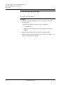
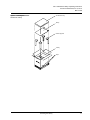
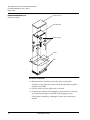
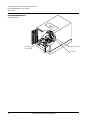
Document 6221100-02, Ver. 2, Rel. 0
March 1999
ATL P1000 Series Library
Unpacking Instructions
0
Introduction....................................................................................................3
Selecting an Installation Location ...............................................................5
Floor Space...............................................................................................5
Floor Clearance .......................................................................................6
Floor Strength and Inclination ..............................................................6
Overhead Clearance ...............................................................................6
Power and Grounding ...........................................................................6
Power Inlet ........................................................................................7
Rack Current Rating Consideration ..............................................7
Grounding .........................................................................................7
Temperature......................................................................................7
Environmental Requirements ...............................................................7
Unpacking the Library..................................................................................8
Unloading Space Requirements ..................................................................9
Uncrating the Library .................................................................................10
Installing the Slide Assembly in the Rack................................................13
Verifying the Rack Requirements.......................................................13
Rack Current Rating Consideration ............................................13
Grounding .......................................................................................14
Temperature....................................................................................14
Determining the Mounting Position ..................................................14
Installing the Slide Assembly in the Rack .........................................15
1
ATL P1000 Series Library Unpacking Instructions
Document 6221100-02, Ver. 2, Rel. 0
March 1999
Adjusting the Slide Assembly ............................................................ 17
Adjusting the Slide Assembly on the Mounting Brackets ....... 17
Adjusting the Slide Assembly Tray on the Slide Rails ............. 19
Removing the Library from the Pallet ..................................................... 22
Removing a Stand-alone Library from the Pallet ............................ 22
Removing a Rack-mount Library from the Pallet ........................... 24
Removing the Internal Packing Materials ............................................... 28
Opening the Doors ............................................................................... 28
Removing the Load and Bulk Packs.................................................. 28
Removing the Shipping Restraint ...................................................... 29
Packaging the Library for Reshipment .................................................... 31
2
ATL P1000 Series Library Unpacking Instructions
Document 6221100-02, Ver. 2, Rel. 0
March 1999
Introduction
0
The ATL P1000 Series is an automated tape library consisting of up to 4
tape drives and 30 DLT™ cartridges.
This document explains how to unpack the ATL P1000 Series. Once the
library is unpacked and moved to the desired installation location, set
up the library using the instructions in the ATL P1000 Series Library
User’s Guide.
The P1000 library is shipped in either a stand-alone (see figure 1) or
rack-mount configuration (see figure 2). The stand-alone P1000 is set
on casters. The rack-mount P1000 comes with a slide tray assembly for
installation in a rack.
Note: A rack is not provided with the rack-mount P1000; it must be obtained
separately.
Figure 1 ATL P1000
Series Library, Stand-alone
Configuration
Window
Key lock
Touch screen
graphical user
interface (GUI)
Bulk pack door
Load pack door
Power switch
Load port
Introduction
3
ATL P1000 Series Library Unpacking Instructions
Document 6221100-02, Ver. 2, Rel. 0
March 1999
Figure 2 ATL P1000
Series Library, Rack-mount
Configuration
Rack (not included)
Key lock
GUI
Bulk pack door
Load pack door
Power switch
Load port
4
Introduction
ATL P1000 Series Library Unpacking Instructions
Document 6221100-02, Ver. 2, Rel. 0
March 1999
Selecting an Installation Location
2
When selecting an installation site for the ATL P1000 Series, consider
the following requirements:
‡
floor space
‡
floor clearance
‡
floor strength and inclination
‡
power and grounding
‡
environmental conditions
These requirements are also described in the ATL P1000 Series Library
User’s Guide.
Floor Space
2
Figure 3 shows the floor space requirements of the stand-alone P1000.
Figure 3 Floor Space
Requirements, Standalone Library
17.5 in.
(45 cm)
24 in. (61 cm)
29.5 in. (75 cm)
Back
Library
Front
54 in. (137.2 cm)
Selecting an Installation Location
5
ATL P1000 Series Library Unpacking Instructions
Document 6221100-02, Ver. 2, Rel. 0
March 1999
Figure 4 shows the floor space requirements for the rack-mount P1000.
Figure 4 Floor Space
Requirements,
Rack-mount Library
24 in.
(61 cm)
each side
24 in. (61 cm)
Front
17.5 in.
(45 cm)
Back
19-inch rack
Library
(extended
from rack)
24 in.
(61 cm)
30 in. (76.2 cm)
Floor Clearance
Floor Strength and
Inclination
4
4
The stand-alone P1000 has a floor clearance of 0.75 in. (1.9 cm). Place
the library on a level, uncarpeted floor free of defects.
The floor at the installation site must be rated at 250 lb/ft2 (1221 kg/
m2). This is sufficient to support a fully loaded P1000 on the floor or in
a rack.
The floor at the installation site must be level to within 0.25 in (6.4 mm)
over a 6 ft by 6 ft (1.8 m by 1.8 m) area.
Overhead Clearance
Power and Grounding
6
4
4
To remove the P1000 enclosure, there must be a minimum clearance of
24 in. (61 cm) above the library. When combined with the height of the
library (21 in./53 cm), this is a total of 45 in. (114.5 cm) from the floor
(stand-alone library) or bottom of the slide (rack-mount library).
The library auto-ranging power supply accepts single-phase, 90 VAC
to 264 VAC input power at 47 Hz to 63 Hz.
Selecting an Installation Location
ATL P1000 Series Library Unpacking Instructions
Document 6221100-02, Ver. 2, Rel. 0
March 1999
Power Inlet
4
The power inlet is an IEC-320 connector (see figure 5). For
international applications, replace the power cord with a harmonized
3 x 1.0 mm2 power cord approved by the country where used.
Ground
Figure 5 AC Power
Receptacle
~100V to 120V / ~200V to 240V
6A/3A 50Hz/60Hz
IEC-320 Type
Line
Neutral
Rack Current Rating Consideration
5
Consider the current rating of the rack before installing more than one
P1000 library. The P1000 library is rated 6A/3A (120V/230V). This
means that no more than two libraries can be installed in a typical
15A/120V rack.
If other equipment is installed in the rack, determine the total current
rating of all the equipment before adding the P1000 library to the rack.
Grounding
5
The P1000 must be connected to a grounded power outlet. If the
library is rack-mounted, the rack must also be grounded.
Temperature
5
The rack temperature should be less than 90qF (32qC).
Environmental
Requirements
5
The installation site (stand-alone library) or the interior of the rack
(rack-mount library) must meet the following environmental
requirements:
‡
humidity: 20% to 80%, non-condensing
‡
temperature: 59qF to 90qF (15qC to 32qC)
‡
altitude: sea level to 10,000 feet (3,033 meters)
Selecting an Installation Location
7
ATL P1000 Series Library Unpacking Instructions
Document 6221100-02, Ver. 2, Rel. 0
March 1999
Unpacking the Library
The P1000 unpacking procedure consists of the following steps:
‡
receiving the library from the shipper (see “Unloading Space
Requirements” on page 9)
‡
uncrating the library (see “Uncrating the Library” on page 10)
‡
installing the slide assembly in the rack (rack-mount library only)
(see “Installing the Slide Assembly in the Rack” on page 13)
‡
removing the library from the pallet (see “Removing the Library
from the Pallet” on page 22)
‡
removing the internal packing materials from the library (see
“Removing the Internal Packing Materials” on page 28)
The following sections detail each of these steps.
Note: Before performing the procedures in the following sections, make sure
the site you have chosen for the installation meets the requirements
listed in “Selecting an Installation Location” on page 5.
8
Unpacking the Library
5
ATL P1000 Series Library Unpacking Instructions
Document 6221100-02, Ver. 2, Rel. 0
March 1999
Unloading Space Requirements
5
Before uncrating the library, verify that you have sufficient space. For
the stand-alone unit, allow a minimum of six feet in front of the ramp
side of the pallet (see figure 6).
Note: Unpack the library as close to the installation site as possible.
Figure 6 Unloading Space
Requirements, Standalone Library
Library
Pallet
Pallet ramp
Unloading area
(minimum)
33 in. (84 cm)
18 in. (46 cm)
97 in. (2.5 m)
30 in. (76 cm)
Unloading Space Requirements
9
ATL P1000 Series Library Unpacking Instructions
Document 6221100-02, Ver. 2, Rel. 0
March 1999
Uncrating the Library
To uncrate the P1000 library:
Procedure
1
Open the top of the shipping carton by carefully cutting the
packaging tape.
The following items are stacked on top of the P1000:
10
‡
accessories tray
‡
ramp (stand-alone library) or slide assembly (rack-mount
library)
2
Remove these items from the carton and set them aside.
3
Remove all foam supports from inside the carton (see figure 7 on
page 11 and figure 8 on page 12).
Uncrating the Library
6
ATL P1000 Series Library Unpacking Instructions
Document 6221100-02, Ver. 2, Rel. 0
March 1999
Accessories tray
Figure 7 Uncrating the
Stand-alone Library
Ramp
Foam supports
Library
Clips
Uncrating the Library
11
ATL P1000 Series Library Unpacking Instructions
Document 6221100-02, Ver. 2, Rel. 0
March 1999
Accessories tray
Figure 8 Uncrating the
Rack-mount Library
Slide assembly
Foam supports
Library
Clips
Procedure (continued)
4
Release the four clips that secure the carton to the pallet.
To release a clip, pinch the center tabs of the clip firmly together
and pull on the tabs.
5
Lift the carton off of the pallet and set it aside.
6
Compare the contents of the shipping carton and the accessories
tray with the packing list included in the shipping carton.
If any items are missing or damaged, contact your authorized
reseller.
12
Uncrating the Library
ATL P1000 Series Library Unpacking Instructions
Document 6221100-02, Ver. 2, Rel. 0
March 1999
Installing the Slide Assembly in the
Rack
8
If you are installing a rack-mount library, install the slide assembly in
the rack before proceeding to “Removing the Library from the Pallet”
on page 22.
This procedure consists of the following steps:
‡
verifying that the rack meets the necessary requirements
‡
determining the mounting position of the slide assembly within
the rack
‡
mounting the slide assembly in the rack
‡
adjusting the slide assembly to allow for required clearances
Warning: Use safe lifting practices when moving the slide assembly
or the library. The slide assembly weighs about 25 lbs
(11.25 kg) and its size and construction make it awkward to
handle. The library weighs 89 lbs (40 kg); it must be lifted
with assistance. Failure to follow these guidelines may
result in equipment damage or personal injury.
Warning: When installing the library and other devices in the rack,
determine the weight of each device and position the
heaviest devices lower in the rack. If the library is the first
device to be installed, place it near the bottom of the rack.
Verifying the Rack
Requirements
8
Before installing the slide assembly in the rack, verify that the rack
meets the following requirements.
Rack Current Rating Consideration
8
Consider the current rating of the rack before installing more than one
P1000 library. The P1000 library is rated 6A/3A (120V/230V). This
means that no more than two libraries can be installed in a typical
15A/120V rack.
If other equipment is installed in the rack, determine the total current
rating of all the equipment before adding the P1000 library to the rack.
Installing the Slide Assembly in the Rack
13
ATL P1000 Series Library Unpacking Instructions
Document 6221100-02, Ver. 2, Rel. 0
March 1999
Grounding
8
The P1000 must be connected to a grounded power outlet. If the
library is rack-mounted, the rack must also be grounded.
Temperature
8
The rack temperature should be less than 90qF (32qC).
Determining the
Mounting Position
8
To determine the mounting position of the slide assembly within the
rack:
Procedure
1
Locate the desired mounting position for the library (see figure 9).
The library and slide assembly require at least 21 in. (54 cm or 12
rack units) of vertical clearance. To ensure stability, mount the
library low in the rack.
Figure 9 Positioning the
Slide Assembly
0.5 in. (12.7 mm)
0.625 in. (16 mm)
1 rack unit (1.75 in. / 4.45 cm)
0.625 in. (16 mm)
0.5 in. (12.7 mm)
Rack retma rail
Mounting bracket
21 in. (54 cm
or 12 rack units)
minimum vertical
clearance required
0.5 in. (12.7 mm)
0.625 in. (16 mm)
1 rack unit
Slide assembly
Locking bracket
Insert temporary support screw here
As indicated in figure 9, the bottom edge of each slide assembly
bracket must line up with the end of a rack unit.
14
Installing the Slide Assembly in the Rack
ATL P1000 Series Library Unpacking Instructions
Document 6221100-02, Ver. 2, Rel. 0
March 1999
Procedure (continued)
2
3
If the rack retma rail holes are not threaded, attach the appropriate
threaded clips to the holes that correspond to:
‡
the mounting bracket tabs (front and back)
‡
the locking bracket tabs (front only)
‡
the temporary support screws (front and back)
Insert a temporary support screw into each retma rail, just below
the desired position of the slide assembly bracket.
Use four of the 10-32 x 3/4 in. slide mounting screws as temporary
support screws.
4
Make sure the support screws are level with one another.
Leave the screws extended out of the retma rails at least 0.625 in.
(16 mm) so they will support the slide assembly mounting brackets
during installation.
Installing the Slide
Assembly in the Rack
To install the slide assembly in the rack (see figure 10 on page 16):
9
Procedure
1
Loosen (but do not remove) the nuts holding the rear mounting
brackets to the slide assembly.
2
Measure the depth of the rack, from the outside edge of the front
retma rail to the outside edge of the rear retma rail.
3
Adjust the rear mounting brackets so that the distance from the
front mounting brackets to the rear mounting brackets is slightly
greater than the depth of the rack.
4
Insert the slide assembly into the rack:
a
Lift the slide assembly and tilt it sideways.
b
Insert the back end of the slide assembly into the front of the
rack, keeping the slide assembly above the temporary support
screws.
c
When the rear brackets clear the rear retma rails, turn the slide
assembly right side up.
d
Place the slide assembly in the rack so that each bracket rests
on a temporary support screw.
5
Secure the front mounting brackets to the front retma rails, using
four 10-32 x 3/4 in. screws from the accessories kit.
6
Adjust the rear mounting brackets so they are flush with the
outside of the rear retma rails.
Installing the Slide Assembly in the Rack
15
ATL P1000 Series Library Unpacking Instructions
Document 6221100-02, Ver. 2, Rel. 0
March 1999
Procedure (continued)
7
Remove the two 10-32 x 3/4 in. temporary support screws from the
front retma rails and install them in the left and right rear
mounting brackets to secure the rear mounting brackets to the rack
retma rails.
8
Remove the two 10-32 x 3/4 in. temporary support screws from the
rear retma rails and use them to finish securing the rear mounting
brackets to the rack retma rails.
Note: Do not tighten the nuts securing the rear mounting brackets to
the slide assembly. You will tighten these during the following
procedure, “Adjusting the Slide Assembly.”
9
Remove the four temporary support screws.
Figure 10 Installing the
Slide Assembly in the Rack
Mounting screws
Retma rails
Support screw
Rear mounting
bracket
Slide assembly
Front mounting bracket
Mounting screws
Support screw
16
Installing the Slide Assembly in the Rack
ATL P1000 Series Library Unpacking Instructions
Document 6221100-02, Ver. 2, Rel. 0
March 1999
Adjusting the Slide
Assembly
Now that the slide assembly is installed in the rack, verify that:
10
‡
The front door of the rack opens and closes freely.
‡
The rear door of the rack opens and closes freely.
‡
When fully extended, the slide assembly extends at least 30 in.
(76.2 cm) from the front of the rack.
If the slide assembly and rack do not meet the above requirements,
complete the procedures in this section to adjust the slide assembly.
The number of adjustments required varies from rack to rack.
Adjusting the Slide Assembly on the Mounting Brackets
10
To adjust the slide assembly on the mounting brackets:
Procedure
1
Loosen the outer nuts on both sides of the slide assembly (see
figure 11).
These nuts secure the mounting brackets to the slide rails.
Outer nuts
Figure 11 Loosening the
Outer Nuts
Outer nuts
2
Move the slide assembly forward or backward as necessary.
Installing the Slide Assembly in the Rack
17
ATL P1000 Series Library Unpacking Instructions
Document 6221100-02, Ver. 2, Rel. 0
March 1999
Procedure (continued)
3
When the slide assembly is in the desired position, tighten all outer
nuts:
a
Pull the slide assembly tray forward until you can access the
four rear screws.
b
Tighten each of the four rear nuts by holding the nut with an
11/32 inch open-ended wrench and then tightening its
corresponding screw with a Phillips screwdriver.
c
Extend the slide assembly out of the rack until both the
intermediate and inner channels of the slide rails lock (see
figure 12).
The intermediate channels are secured by the intermediate
channel locks, which are located on the inner, back edge of the
intermediate channels.
d
Release the intermediate channel locks by rotating them
upward slightly.
Note: Do not release the inner channel locks.
e
Push the slide assembly back into the rack until the access hole
on the inside of the intermediate channel exposes a screw.
f
Use a Phillips screwdriver to tighten the screw while holding
its corresponding nut with an 11/32 inch open-ended wrench.
g
Repeat steps 3e and 3f to tighten the remaining front nuts.
h
Press on the inner channel locks to release them.
The inner channel locks are located on the outer, back edge of
the inner channels.
i
4
18
Push the slide assembly tray back into the rack.
Check for clearance. If necessary, repeat this procedure to adjust
the slide assembly further.
Installing the Slide Assembly in the Rack
ATL P1000 Series Library Unpacking Instructions
Document 6221100-02, Ver. 2, Rel. 0
March 1999
Figure 12 Slide Assembly
Tray, Fully Extended
Intermediate
channel lock
Access hole
Intermediate channel
Inner channel lock
Inner channel
Adjusting the Slide Assembly Tray on the Slide Rails
12
To adjust the slide assembly tray on the slide rails:
Procedure
1
Loosen the inner nuts on both sides of the slide assembly (see
figure 13).
Access these nuts from underneath the slide assembly tray.
2
Move the slide assembly tray forward or backward as necessary.
Installing the Slide Assembly in the Rack
19
ATL P1000 Series Library Unpacking Instructions
Document 6221100-02, Ver. 2, Rel. 0
March 1999
Inner nuts
Figure 13 Loosening the
Inner Nuts
Inner nuts
Procedure (continued)
3
When the slide assembly tray is in the desired position, tighten all
inner nuts:
a
Extend the slide assembly out of the rack until both the
intermediate and inner channels of the slide rails lock (see
figure 12).
This allows you to access the front screws.
20
b
Tighten each of the front nuts by holding the nut with an
11/32 inch open-ended wrench and then tightening its
corresponding screw with a Phillips screwdriver.
c
Press on the inner channel locks to release them (see figure 12).
d
Push the slide assembly back into the rack until the access hole
on the outside of the inner channel exposes a screw.
Installing the Slide Assembly in the Rack
ATL P1000 Series Library Unpacking Instructions
Document 6221100-02, Ver. 2, Rel. 0
March 1999
Procedure (continued)
4
e
Use a Phillips screwdriver to tighten the screw while holding
its corresponding nut with an 11/32 inch open-ended wrench.
f
Repeat steps 3d and 3e to tighten the remaining inner nuts.
g
Push the slide assembly tray back into the rack.
Check for adequate clearance. If necessary, repeat this procedure to
adjust the slide tray further.
Now that the slide assembly is properly installed and adjusted, you
are ready to remove the P1000 from the shipping pallet and mount it in
the rack.
Installing the Slide Assembly in the Rack
21
ATL P1000 Series Library Unpacking Instructions
Document 6221100-02, Ver. 2, Rel. 0
March 1999
Removing the Library from the Pallet
This section provides separate procedures for the stand-alone and
rack-mount libraries:
‡
To remove a stand-alone library from the pallet, see the following
section, “Removing a Stand-alone Library from the Pallet.”
‡
To remove a rack-mount library from the pallet, see “Removing a
Rack-mount Library from the Pallet” on page 24.
Warning: Two people should perform steps that involve lifting or
guiding the library. Use safe practices when lifting or
guiding the library and handling the slide assembly or the
ramp.
Removing a
Stand-alone Library
from the Pallet
To remove a stand-alone library from the pallet:
13
Procedure
1
2
22
Remove the plastic bag enclosing the P1000:
a
Cut along the front seam of the plastic bag.
b
Continue to cut all the way to the back of the library.
c
Fold the bag out of the way.
Remove the foam supports from between the library and the pallet
(see figure 14).
Removing the Library from the Pallet
13
ATL P1000 Series Library Unpacking Instructions
Document 6221100-02, Ver. 2, Rel. 0
March 1999
Figure 14 Removing the
Foam Supports,
Stand-alone Library
Foam supports
Procedure (continued)
3
Attach the ramp to the pallet using fastener strips (see figure 15).
4
Make any necessary preparations for moving the library.
This may involve clearing a path to the installation site, unlocking
doors, and placing mats over carpeted areas.
5
Carefully roll the library down the ramp.
Figure 15 Removing the
Stand-alone Library from
the Pallet
Fastener strips
6
Detach the ramp and place it on top of the pallet.
Removing the Library from the Pallet
23
ATL P1000 Series Library Unpacking Instructions
Document 6221100-02, Ver. 2, Rel. 0
March 1999
Procedure (continued)
7
Roll the library to the installation site.
8
Save the shipping carton, bag, foam supports, ramp, and pallet for
future use.
These items are required to package the library for reshipment.
Removing a
Rack-mount Library
from the Pallet
To remove a rack-mount library from the pallet:
15
Note: The instructions in this section assume you have already installed the
slide assembly in the rack. If you have not, do so now, following the
instructions in “Installing the Slide Assembly in the Rack” on page 13.
Procedure
1
2
Remove the plastic bag enclosing the library:
a
Cut along the front seam of the plastic bag.
b
Continue to cut all the way to the back of the library.
c
Fold the bag out of the way.
Pull the slide tray forward in the rack so it is fully extended.
Warning: The rack may tip forward when you extend the slide tray or
place the library on the slide tray. If rack stabilizing feet are
present, extend them during this procedure. If the rack
does not have stabilizing feet, use extreme caution when
extending the slide tray and mounting the P1000 in the
rack.
24
Removing the Library from the Pallet
ATL P1000 Series Library Unpacking Instructions
Document 6221100-02, Ver. 2, Rel. 0
March 1999
Procedure (continued)
3
With the help of a second person, lift the library from the pallet (see
figure 16).
Figure 16 Lifting the
Rack-mount Library from
the Pallet
Library
Shipping bag
Foam supports
Pallet
Removing the Library from the Pallet
25
ATL P1000 Series Library Unpacking Instructions
Document 6221100-02, Ver. 2, Rel. 0
March 1999
Procedure (continued)
4
Place the library on the fully extended slide assembly tray (see
figure 17).
Figure 17 Placing the
Library on the Slide
Assembly Tray
Inner channel lock
Screws
26
5
Secure the library to the slide tray, using six screws from the
accessories kit (see figure 17).
6
Verify that, when the slide assembly is fully extended, there is
adequate clearance around the library to access the back panel and
remove the library enclosure.
7
Press on the inner channel locks to release them (see figure 17) and
then push the slide assembly all the way into the rack.
Removing the Library from the Pallet
ATL P1000 Series Library Unpacking Instructions
Document 6221100-02, Ver. 2, Rel. 0
March 1999
Procedure (continued)
8
To prevent the library from sliding out of the rack during
operation, secure the locking brackets to the retma rails (see
figure 18).
Figure 18 Locking the
Slide Tray in the Rack
Retma rail
Locking bracket
9
Save the shipping carton, bag, foam supports, and pallet for future
use.
These items are required to package the library for reshipment.
Removing the Library from the Pallet
27
ATL P1000 Series Library Unpacking Instructions
Document 6221100-02, Ver. 2, Rel. 0
March 1999
Removing the Internal Packing
Materials
This section explains how to remove the internal packing materials
that protect the library during shipping and installation.
Opening the Doors
18
Caution:
Before removing the internal packing materials, verify that
the library is at its final installation site. Moving the library
without these materials in place may damage the library.
Caution:
Take precautions to prevent electrostatic discharge
whenever you remove the library enclosure or open the
library doors.
To open the library doors:
Procedure
Removing the Load
and Bulk Packs
1
Locate the key in the accessories kit and unlock the front door of
the library.
2
Open the left door first, then open the right door.
To remove the load and bulk packs (see figure 19):
18
Procedure
1
Grip the load pack handles and squeeze them together.
This releases the latches securing the load pack.
28
2
Still holding the load pack handles, pull the load pack forward and
out of the library.
3
Repeat steps 1 and 2 to remove the bulk pack.
Removing the Internal Packing Materials
18
ATL P1000 Series Library Unpacking Instructions
Document 6221100-02, Ver. 2, Rel. 0
March 1999
Figure 19 Removing the
Load and Bulk Packs
Handles
Removing the
Shipping Restraint
To remove the shipping restraint:
19
Note: The shipping restraint that protects the extension axis assembly is
attached to the bottom drive shelf and fits over the supports for the
load and bulk packs.
Procedure
1
Grasp the front edge of the shipping restraint and carefully push
inward at both corners while lifting it up at an angle (see figure 20).
The tab on the shipping restraint (between the mounting blocks for
the load and bulk packs) pops up, releasing the shipping restraint
from the load pack shelf. The back of the shipping restraint
unhooks from the bottom drive shelf.
2
Lift the shipping restraint off the extension axis assembly.
3
Raise the extension axis assembly and remove the foam block
beneath it.
4
Lower the extension axis assembly to its normal position on the
floor of the library.
Note: Retain the original shipping container and shipping bag, pallet,
ramp, accessories tray, and all packing materials for future use.
Removing the Internal Packing Materials
29
ATL P1000 Series Library Unpacking Instructions
Document 6221100-02, Ver. 2, Rel. 0
March 1999
Figure 20 Removing the
Shipping Restraint
Extension
axis assembly
Shipping restraint
Drive shelf
30
Removing the Internal Packing Materials
ATL P1000 Series Library Unpacking Instructions
Document 6221100-02, Ver. 2, Rel. 0
March 1999
Packaging the Library for Reshipment
20
If it becomes necessary to reship the library, repackage the library in its
original shipping materials as follows:
Procedure
1
Unload and eject all tape cartridges from the tape drives.
2
Turn off the library and disconnect all cables.
3
Open the library doors:
4
a
Using the key in the accessories kit, unlock the front door of the
library.
b
Open the left door first, then open the right door.
Remove the load and bulk packs (see figure 19 on page 29):
a
Grip the load pack handles and squeeze them together.
This releases the latches securing the load pack.
b
Still holding the load pack handles, pull the load pack forward
and out of the library.
c
Repeat steps 4a and 4b to remove the bulk pack.
Note: In order to install the shipping restraint, the gripper must face
the front of the library.
5
If the gripper is facing the tape drives, rotate the extension axis so
that the gripper faces the front of the library:
a
Reaching through the library doors, move the gripper
backwards (away from the tape drives) and compress it against
its rear limit.
This unlocks the rotary assembly and permits the extension
axis to rotate.
6
b
Rotate the extension axis assembly 180° so that the gripper
faces the front of the library.
c
Jiggle the extension assembly slightly to relatch the rotary
assembly.
Secure the extension axis assembly:
a
Center the extension axis assembly between the mounting
blocks for the load and bulk packs.
b
Raise the extension axis assembly and place the foam block
beneath it.
Packaging the Library for Reshipment
31
ATL P1000 Series Library Unpacking Instructions
Document 6221100-02, Ver. 2, Rel. 0
March 1999
Procedure (continued)
c
Carefully lower the extension axis assembly so that it rests on
the foam block.
d
Hook the lip of the shipping restraint under the edge of the
bottom drive shelf (see figure 20 on page 30).
e
Move the gripper forward or backward as necessary so that it
fits underneath the shipping restraint.
f
Press the front edge of the shipping restraint downward until
the tab on the shipping restraint snaps into place.
7
Replace the load and bulk packs.
8
Close and lock the library doors.
9
Recrate the library:
a
Place the library in the shipping bag.
b
Place the library on the shipping pallet.
c
Replace the foam supports between the library and the pallet
(see figure 14 on page 23).
d
Place the shipping carton over the library and secure it with the
four clips.
e
Replace the foam supports inside the shipping carton.
f
Place the ramp (stand-alone library) or slide assembly (rackmount library) on top of the library (see figure 7 on page 11 and
figure 8 on page 12).
g
Place the accessories tray on top of the ramp or slide assembly.
h
Close and seal the shipping carton.
The library is now ready for reshipment.
32
Packaging the Library for Reshipment