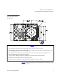
1
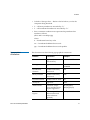
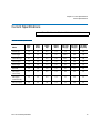
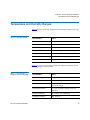
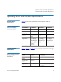
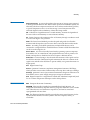
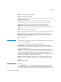
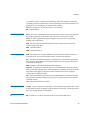
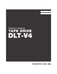
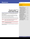
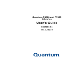
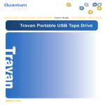
3URGXFW6SHFLILFDWLRQ 3URGXFW6SHFLILFDWLRQ 3URGXFW6SHFLILFDWLRQ
7DSH'ULYH
'/79
$
DLT-V4 Product Specification, 81-81349-02 A01, November 2005, Made in USA.
Quantum Corporation provides this publication “as is” without warranty of any kind, either express or
implied, including but not limited to the implied warranties of merchantability or fitness for a particular
purpose. Quantum Corporation may revise this publication from time to time without notice.
COPYRIGHT STATEMENT
Copyright 2005 by Quantum Corporation. All rights reserved.
Your right to copy this document is limited by copyright law. Making copies or adaptations without prior
written authorization of Quantum Corporation is prohibited by law and constitutes a punishable violation of
the law.
TRADEMARK STATEMENT
Quantum, the Quantum logo, DLT, DLTtape, the DLTtape logo, and Super DLTtape logo are all registered
trademarks of Quantum Corporation. DLTIce, DLTSage, and Super DLTtape are all trademarks of Quantum
Corporation.
Other company and product names used in this document are trademarks, registered trademarks, or service
marks of their respective owners.
Contents
Preface
Chapter 1
ix
Physical Specifications
1
Physical Description ........................................................................................................ 2
Physical Dimensions and Weights ......................................................................... 2
Internal Tape Drive Mounting Hole Dimensions........................................................ 4
Chapter 2
Functional Specifications
7
Chapter 3
Performance Specifications
9
Timing Characteristics ................................................................................................... 10
Data Cartridge and Media Characteristics ................................................................. 11
Reliability Factors ........................................................................................................... 11
Chapter 4
Power Specifications
12
Current Specifications.................................................................................................... 13
External Power Supply and Chassis Requirements .................................................. 14
DLT-V4 Product Specification
iii
Contents
Chapter 5
Environmental Specifications
15
Temperature and Humidity Ranges............................................................................ 16
Altitude ............................................................................................................................ 17
Chapter 6
Shock and Vibration Specifications
18
Operating Shock and Vibration Specifications .......................................................... 19
Operating Shock Specifications............................................................................. 19
Operating Vibration Specifications ...................................................................... 19
Non-operating Shock and Vibration Specifications .................................................. 21
Non-operating Shock Specifications .................................................................... 21
Non-operating Packaged Vibration Specifications ............................................ 21
Non-operating Unpackaged Vibration Specifications....................................... 23
Chapter 7
Emission and Immunity Specifications
24
Emissions ......................................................................................................................... 24
Radiated Emissions................................................................................................. 25
Conducted Emissions ............................................................................................. 25
Harmonic Current Emissions ................................................................................ 25
Acoustic Noise Emissions ...................................................................................... 27
Immunities ...................................................................................................................... 28
Electrostatic Discharge (ESD) Immunity ............................................................. 28
Radiated Immunity................................................................................................. 28
Fast Transient Immunity........................................................................................ 29
Surge Immunity....................................................................................................... 29
Conducted Immunity ............................................................................................. 29
Power Frequency Magnetic Field Immunity ...................................................... 29
Voltage Dips, Short Interruptions, and Variations Immunity.......................... 30
Voltage Fluctuations and Flicker Limits ..................................................................... 31
Direct Current (DC) Magnetic Field Interference...................................................... 31
Chapter 8
Safety Specifications
32
Safety Requirement ........................................................................................................ 32
Consumer Bulletin Scheme ........................................................................................... 32
DLT-V4 Product Specification
iv
Contents
Appendix A
Regulatory Statements
33
Environmental Compliance .......................................................................................... 37
Disposal of Electrical and Electronic Equipment ...................................................... 37
Glossary
DLT-V4 Product Specification
38
v
Figures
Figure 1
Internal Tape Drive Mounting Hole Dimensions (Bottom View) ....... 5
Figure 2
Mounting Hole Dimensions (Side View) ................................................ 6
DLT-V4 Product Specification
vi
Tables
Table 1
Physical Dimensions .................................................................................... 2
Table 2
Weight Specifications ................................................................................... 2
Table 3
Proper and Acceptable DLT-V4 Tape Drive Orientation........................3
Table 4
Functional Specifications .............................................................................7
Table 5
Tape Drive Timing Characteristics........................................................... 10
Table 6
Data Cartridge and Media Characteristics.............................................. 11
Table 7
Reliability Factors ....................................................................................... 11
Table 8
Current Specifications ................................................................................ 13
Table 9
Common Mode Noise Limitations........................................................... 14
Table 10
Operating Ranges ....................................................................................... 16
Table 11
Non-Operating Ranges (Packed or Unpacked)...................................... 16
Table 12
Half Sine Wave Pulse Shock Operating Vibration Specifications ....... 19
Table 13
Random Overstress Operating Vibration Specifications ...................... 19
Table 14
Random Overstress Operating Vibration Specifications
(PSD Spectrum) ....................................................................................... 20
Table 15
Sweep / Dwell Operating Vibration Specifications .............................. 20
Table 16
Non-operating (Unpackaged) Shock Specifications ..............................21
DLT-V4 Product Specification
vii
Tables
Table 17
Random Survival Non-operating (Packaged) Vibration
Specifications ........................................................................................... 21
Table 18
Random Overstress Non-operating Vibration Specifications
(PSD Spectrum) ....................................................................................... 22
Table 19
Impact Drop Non-operating (Packaged) Shock (Drop)
Specifications ........................................................................................... 22
Table 20
Random Non-operating (Unpackaged) Vibration Specifications........ 23
Table 21
Standalone Random Non-operating (Unpackaged) Vibration
Specifications (PSD Spectrum).............................................................. 23
Table 22
Sweep/Dwell Non-operating (Unpackaged) Vibration
Specifications ........................................................................................... 23
Table 23
Radiated Emissions Limits ........................................................................ 25
Table 24
Conducted Emissions Limits..................................................................... 25
Table 25
Odd Harmonic Limits for Class A Equipment Limits .......................... 26
Table 26
Even Harmonic Limits for Class A Equipment...................................... 26
Table 27
Acoustic Noise Emissions, Nominal ........................................................ 27
Table 28
Acoustic Noise Declaration for German Noise Declaration Law ........ 27
Table 29
Electrostatic Discharge (ESD) Immunity Limits..................................... 28
Table 30
Radiated Immunity Limits ...................................................................... 29
Table 31
Fast Transient Immunity Limits ............................................................... 29
Table 32
Surge Immunity Limits .............................................................................. 29
Table 33
Conducted Immunity Limits..................................................................... 29
Table 34
Magnetic Field Immunity Limits.............................................................. 30
Table 35
Voltage Dips, Short Interruptions, and Variations Immunity
Limits ........................................................................................................ 30
Table 36
Voltage Fluctuations and Flicker Limits.................................................. 31
DLT-V4 Product Specification
viii
Preface
This document serves as an easy-to-use information source to familiarize
Quantum customers and systems professionals with the DLT-V4 tape
drive system. The DLT-V4 tape drive is an extension of Quantum’s
Digital Linear Tape (DLT®) product family.
This chapter describes the purpose, scope, and audience of this
document. It also lists the typographical conventions used in this
document.
Purpose
0
This document describes the tape drive, listing its physical, functional,
and performance specifications, and describing the standards that the
tape drive meets.
Audience
0
The primary audience for this document consists of engineers and
technicians interested in integrating the tape drive into tape libraries and
other equipment.
Document Organization 0
DLT-V4 Product Specification
This document is organized as follows:
•
Chapter 1, Physical Specifications, contains the physical description
of the DLT-V4 tape drive, including the internal and tabletop tape
drives, and the environmental temperature and humidity
specifications.
•
Chapter 2, Functional Specifications, contains the functional
specifications of the DLT-V4 tape drive, including the LED functions.
ix
Preface
Notational Conventions
•
Chapter 3, Performance Specifications, describes the performance
specifications of the DLT-V4 tape drive, including timing
characteristics, data cartridge and media characteristics, and the
reliability factors of the tape drive.
•
Chapter 4, Power Specifications, describes the power specifications of
the DLT-V4 tape drive.
•
Chapter 5, Environmental Specifications, describes the
environmental specifications of the DLT-V4 tape drive.
•
Chapter 6, Shock and Vibration Specifications, describes the shock
and vibration specifications of the DLT-V4 tape drive. All testing was
done on both the internal and tabletop tape drives.
•
Chapter 7, Emission and Immunity Specifications, describes the
emission and immunity specifications of the DLT-V4 tape drive.
•
Chapter 8, Safety Specifications, describes the safety specifications of
the DLT-V4 tape drive.
•
Appendix A, Regulatory Statements, provides the regulatory
statements of the DLT-V4 tape drive.
This document uses the following conventions:
Note:
Notes emphasize important information related to the main
topic.
Caution:
Cautions indicate potential hazards to equipment and are
included to prevent damage to equipment.
Warning:
Warnings indicate potential hazards to personal safety and
are included to prevent injury.
This document uses the following:
DLT-V4 Product Specification
•
Tape Drive System — Refers to the complete system including the
cartridge.
•
Tape Drive — Refers to just the tape drive and does not include the
cartridge.
•
Right side of the tape drive — Refers to the right side as you face the
component being described.
x
Preface
•
Left side of the tape drive — Refers to the left side as you face the
component being described.
•
b — All binary numbers are succeeded by “b.”
•
h — All hexadecimal numbers are succeeded by “h.”
•
Error or attention conditions are represented in parenthesis that
translate as follows:
(SK=S ASC=AA ASCQ=QQ)
where:
S — hexadecimal sense key value
AA — hexadecimal additional sense code
QQ — hexadecimal additional sense code qualifier
Typographical
Conventions
DLT-V4 Product Specification
This document uses the following typographical conventions:
0
Element
Convention
Example
Commands
Uppercase (unless
case-sensitive)
FORMAT UNIT
Messages
Uppercase
INVALID PRODUCT
NUMBER
Hexadecimal
Notation
Number followed by
lowercase h
25h
Binary Notation
Number followed by
lowercase b
101b
Decimal Notation
Number without suffix
512
Acronyms
Uppercase
POST
Abbreviations
Lowercase, except
where standard usage
requires uppercase
Mb (megabits)
MB (megabytes)
Dimensions in
Figures
No units specified
(Inches understood
unless otherwise
specified)
0.57 EJECT DISTANCE
xi
Preface
Related Documents
The following documents are related to the DLT-V4 tape drive:
Document No.
Document Title
Document Description
81-81252-xx
Bezel Replacement
Guide
Provides bezel replacement
instructions
81-81422-xx
DLT-V4 Product
Manual
Provides detailed product
information for the tape
drive.
81-81355-xx
DLT-V4 Quick Start
Guide
Provides basic tape drive
installation instructions.
Current SCSI standards documents available from www.t10.org
• SCSI Architecture Model (SAM-3)
• SCSI Primary Commands (SPC-3)
• SCSI Parallel Interface (SPI-5)
• SCSI Stream Commands (SSC-3)
Current SATA standards documents available from www.serialata.org
• Serial ATA 1.0a Specification
SCSI Standards
0
Copies of the approved version of the SCSI standards may be obtained
from:
Global Engineering Documents
15 Inverness Way, East
Englewood, CO 80112
(800) 854-7179 or (303) 397-2740
DLT-V4 Product Specification
xii
Preface
Contacts
0
Quantum company contacts are listed below.
Quantum Corporate Headquarters
0
To order documentation on this or other Quantum products, contact:
Quantum Corporation
141 Innovation Drive
Irvine, CA 92617
(949) 856-7800
(800) 284-5101
0
Technical Publications
To comment on existing documentation send e-mail to:
[email protected]
0
Quantum Home Page
Visit the Quantum home page at:
http://www.quantum.com
0
Customer Support
The Quantum Customer Support Department provides a 24-hour help
desk that can be reached at:
North/South America:
(949) 725-2100 or (800) 284-5101
Asia/Pacific Rim:
(International Code) + 61 7 3839 0988
Europe/Middle East/Africa: (International Code) + 44 (0) 1256 848748
Send faxes for the Customer Support Department to:
North/South America:
(949) 725-2176
Asia/Pacific Rim:
(International Code) + 61 7 3839 0955
Europe/Middle East/Africa: (International Code) + 44 (0) 1256 848777
DLT-V4 Product Specification
xiii
Preface
Send e-mail for the Customer Support Department to:
North/South America:
http://www.quantum.com/am/service_support/
Index.aspx
Asia/Pacific Rim:
[email protected]
Europe/Middle East/Africa: [email protected]
DLT-V4 Product Specification
xiv
Chapter 1
Physical Specifications
1
This chapter contains the physical description of the DLT-V4 tape drive,
including the internal and tabletop tape drives, and the environmental
temperature and humidity specifications.
DLT-V4 Product Specification
1
Chapter 1 Physical Specifications
Physical Description
Physical Description
1
Physical Dimensions and
Weights
1
Table 1 Physical Dimensions
Table 2 Weight Specifications
Specification
Internal Tape Drive
Tabletop Tape Drive
Height
1.656 in. (42.05 mm)
with the bezel
1.618 in. (41.10 mm)
without the bezel
2.608 in. (66.24 mm)
Width
5.748 in. (146.00 mm)
behind the bezel
5.807 in. (147.50 mm)
with the bezel
8.352 in. (212.13 mm)
Length
8.614 in. (218.80 mm)
measured from the rear
of the front bezel
8.874 in. (225.40 mm)
including the bezel
10.728 in. (272.49 mm)
Specification
Internal Tape Drive
Tabletop Tape Drive
Unit Weight
3.00 lb. (1.36 kg)
8.00 lb. (3.63 kg)
Shipping Weight
4.39 lb. (1.99 kg)
depending on the
configuration
11.81 lb. (5.36 kg)
depending on the
configuration
Table 3 shows the acceptable operating orientation for the DLT-V4 tape
drive.
DLT-V4 Product Specification
2
Chapter 1 Physical Specifications
Physical Description
Table 3 Proper and
Acceptable DLT-V4 Tape Drive
Orientation
Orientation
Internal Tape Drive
Tabletop Tape Drive
Top Side Up
(typical)
Left Side
Down
Right Side
Down
DLT-V4 Product Specification
3
Chapter 1 Physical Specifications
Internal Tape Drive Mounting Hole Dimensions
Internal Tape Drive Mounting Hole Dimensions
1
Figure 1 shows the mounting holes and dimensions in a bottom view for
the internal tape drive.
DLT-V4 Product Specification
4
Chapter 1 Physical Specifications
Internal Tape Drive Mounting Hole Dimensions
Figure 1 Internal Tape Drive
Mounting Hole Dimensions
(Bottom View)
Data cartridge
Notes: The following is additional information for figure 1.
• The dimension referenced in boxed note [1] is from the front of the base plate.
• The dimension referenced in boxed note [2] is from the right-side tape drive mounting plane to the
interior guiding surface of the media opening.
• The dimension referenced in boxed note [3] is from the bottom tape drive mounting hole to the
interior guiding surface of the media opening.
• The tape drive width and length are standard 5¼-inch form factor measurements.
• Dimensions are identical on left side and right sides.
• Dimensions are in millimeters. The dimensions in brackets [x.x] are in inches.
Figure 2 shows the mounting holes and dimensions in a side view for the
internal tape drive.
DLT-V4 Product Specification
5
Chapter 1 Physical Specifications
Internal Tape Drive Mounting Hole Dimensions
Figure 2 Mounting Hole
Dimensions (Side View)
Data cartridge
Notes: The following is additional information for figure 2.
• The dimension referenced in boxed note [1] is from the front of the base plate.
• The dimension referenced in boxed note [2] is from the bottom tape drive mounting plane to the
interior guiding surface of the media opening.
• Boxed note [3] states that the data cartridge is shown in the ejected position.
• The tape drive width and length are standard 5¼-inch form factor measurements.
• Dimensions are identical on left side and right sides.
• Dimensions are in millimeters. The dimensions in brackets [x.x] are in inches.
DLT-V4 Product Specification
6
Chapter 2
2
Functional Specifications
This chapter contains the functional specifications of the DLT-V4 tape
drive, including the LED functions.
Table 4 lists the key functional specifications of the DLT-V4 tape drive.
Table 4 Functional
Specifications
DLT-V4 Product Specification
Specification
Value
Formatted Capacity,
Native Mode
160 gigabytes (GB)
Formatted Capacity,
Compressed Modea
320 GB
Interface
Low-Voltage Differential (LVD)
Tape Drive Type
DLT Derivative, streaming; 16-bit LVD
Recording Type
Partial Response Maximum Likelihood
(PRML)
Read Compatibilityb
DLT-V4, DLT VS160, DLT VS80 / DLT1
Write Compatibility
DLT-V4
Form Factor
5¼-in. Half-height
Sustained Transfer
Rate, Native Mode
Up to 10 megabyte (MB) per second
7
Chapter 2 Functional Specifications
Specification
Value
Sustained Transfer
Rate, Compressed
Modea
Up to 20 MB / sec
Transfer Rate, Burst
160 MB / sec
Error Rate
(Unrecoverable)
1 in 1017 bits (non-media error)
a. Compressed values use a nominal 2:1 compression ratio.
Actual compression ratios achieved depend on the
redundancy of data files being recorded.
b. Performance may vary when the tape drive reads data
previously written to the DLT VS80 and DLT1 formatted data
cartridges. Performance depends on the quality of the data
cartridge you are reading, not the DLT-V4 tape drive.
DLT-V4 Product Specification
8
Chapter 3
Performance Specifications
3
This chapter describes the performance specifications of the DLT-V4 tape
drive, including timing characteristics, data cartridge and media
characteristics, and the reliability factors of the tape drive.
DLT-V4 Product Specification
9
Chapter 3 Performance Specifications
Timing Characteristics
Timing Characteristics
3
Table 5 lists the timing characteristics of the DLT-V4 tape drive.
Table 5 Tape Drive Timing
Characteristics
DLT-V4 Product Specification
Specification
Value
Read/Write Tape Speed
118 inches per second
Rewind Tape Speed
160 inches per second
Linear Search Tape Speed
118 inches per second
Average Rewind Time
68 seconds
Maximum Rewind Time
135 sec
Average Access Time (BOT)
84 sec
Maximum Access Time (from BOT)
168 sec
Load to BOT — previously recorded tape
90 sec
Unload from BOT
22 sec (no brush), 61
sec (brush)
10
Chapter 3 Performance Specifications
Data Cartridge and Media Characteristics
Data Cartridge and Media Characteristics
3
Table 6 lists the data cartridge and media characteristics.
Table 6 Data Cartridge and
Media Characteristics
Characteristic
Specification
Media Width
0.5 in.
Media Length
1,847 ft
Media Type
Metal Particle
Data Cartridge Dimensions
4.1 in. x 4.1 in. x 1.0 in.
Shelf Life
30 years minimum @ 20 ºC and 40%
relative humidity (non-condensing)
Usage
600 hrs (150 full read/write uses)
Reliability Factors
3
Table 7 lists the reliability factors for the DLT-V4 tape drive.
Table 7 Reliability Factors
DLT-V4 Product Specification
Factor
Hours / Cycles
Comments
Head Life
30,000 tape
motion hours
Continuous operation.
MTBF
250,000 hours
Quantum Corporation does not
warrant that predicted MTBF is
representative of any particular
unit installed for customer use.
Actual figures vary from unit to
unit.
MTBF is measured at 100% duty
cycle, excluding head life.
Load/Unload
50,000 cycles
This excludes media errors.
11
Chapter 4
4
Power Specifications
This chapter describes the power specifications of the DLT-V4 tape drive.
DLT-V4 Product Specification
12
Chapter 4 Power Specifications
Current Specifications
Current Specifications
Note:
4
The +5 Volt bus is ±5%; the +12 Volt bus is ±10%.
Table 8 Current Specifications
5VDC
Apk
5VDC
Arms
12VDC
Apk
12VDC
Arms
DC Pwr
W (typ)
AC Pwr
W (typ)
AC Pwr
W (max)
Power Up
1.6
1.2
0.3
0.1
7.2
9
18
Load Tape
1.6
1.3
2.7
0.7
14.9
20
24
Unload Tape
1.6
1.3
2.6
0.8
16.1
20
24
Write Tape
1.9
1.6
1.4
0.5
14
20
21
Read Tape
1.9
1.4
1.3
0.5
13
19
21
Rewind
1.5
1.4
1.4
0.5
13
17
19
Idle (tape
tensioned)
1.3
1.3
0.6
0.2
8.9
13
14
Idle (tape
untensioned)
1.3
1.3
0.3
0.1
7.7
12
13
Idle (no tape)
1.3
1.3
0.1
0.1
7.7
12
13
Mode
DLT-V4 Product Specification
13
Chapter 4 Power Specifications
External Power Supply and Chassis Requirements
External Power Supply and Chassis Requirements
4
This section lists the common mode noise limitations between enclosures.
The noise level cannot exceed the values listed in the following table. All
measurements must be administered with an active or differential probe
to reduce oscilloscope ground loops.
Table 9 Common Mode Noise
Limitations
DLT-V4 Product Specification
First Enclosure
Second Enclosure
Common Mode
Noise Limit
Millivolt (mV)
Enclosure Chassis
(Host Server,
Workstation, or DLTV4 Tabletop Enclosure)
DLT-V4 Tape Drive
Chassis
<1 mV
Peak to Peak
Enclosure Chassis
(Host Server,
Workstation, or DLTV-4 Tabletop
Enclosure)
Power Supply
Enclosure Ground
<300 mV
Peak to Peak
14
Chapter 5
Environmental Specifications
5
This chapter describes the environmental specifications of the DLT-V4
tape drive.
The tape drive operates in environments that include general offices and
workspaces that consist of:
•
Conditioned and marginally-conditioned areas with central or
remote air-conditioning
•
Complete temperature and humidity controls
•
Moderate control tolerances
•
Systems capable of maintaining consistent comfort levels.
The tape drive does not conform to environments that consist of:
•
Marginal heating or cooling apparatus
•
No humidity conditioning
•
Uncontrolled tolerances
•
Systems inadequate to maintain constant comfort levels.
For long-term trouble-free operation, we strongly recommend that you
operate and store the tape drive in a clean, smoke-free environment.
The following tables provide the operating, non-operating, storage, and
shipping environmental specifications for the DLT-V4 tape drive systems
(both the internal and the tabletop configurations).
DLT-V4 Product Specification
15
Chapter 5 Environmental Specifications
Temperature and Humidity Ranges
Temperature and Humidity Ranges
5
Table 10 lists the operating temperature and humidity ranges of the tape
drive.
Table 10 Operating Ranges
Specification
Value
Temperature Range
10 ºC to 40 ºC (50 ºF to 104 ºF)
Airflow
3.0 CFM (min.)
Wet Bulb Temperature
25 ºC (77 ºF)
Temperature Gradient
11 ºC (19.8 ºF) per hour (across range)
Temperature Shock
10 ºC (18 ºF) over two minutes
Relative Humidity
20% to 80% non-condensing
Humidity Gradient
10% per hour
Table 11 lists the non-operating storage and shipment temperature and
humidity ranges of the tape drive.
Table 11 Non-Operating
Ranges (Packed or Unpacked)
DLT-V4 Product Specification
Specification
Value
Dry Bulb Temperature
-40 ºC to 66 ºC (-40 ºF to 150.8 ºF)
Wet Bulb Temperature
46 ºC (114.8 ºF)
Temperature Gradient
20 ºC (36 ºF) per hour with 5º margin
(across the range)
Temperature Shock
15 ºC (27 ºF) with 5º margin (over two
minutes)
Relative Humidity
10% to 95% non-condensing
Humidity Gradient
10% per hour
16
Chapter 5 Environmental Specifications
Altitude
Altitude
5
The tape drive operates normally in pressures from -500 feet to 30,000
feet.
DLT-V4 Product Specification
17
Chapter 6
6
Shock and Vibration
Specifications
This chapter describes the shock and vibration specifications of the DLTV4 tape drive. All testing was done on both the internal and tabletop tape
drives.
DLT-V4 Product Specification
18
Chapter 6 Shock and Vibration Specifications
Operating Shock and Vibration Specifications
Operating Shock and Vibration Specifications
Operating Shock
Specifications
6
Table 12 Half Sine Wave
Pulse Shock Operating
Vibration Specifications
Operating Vibration
Specifications
6
Table 13 Random Overstress
Operating Vibration
Specifications
DLT-V4 Product Specification
6
Table 12 lists the shock specifications for the tape drive while it is
operating.
Specification
5 G Shock
8 G Shock
62 G Shock
Pulse Shape
½ Sine Pulse
½ Sine Pulse
½ Sine Pulse
Peak
Acceleration
5G
8G
62 G
Duration
11 millisecond
(ms)
10 ms
2 ms
Application
X, Y, and Z
axis, 10 pulses
per axis (± ), 60
total, 1 pulse
every 6
seconds
X, Y, and Z
axis, 1 pulse
per axis (± ), 6
total
X, Y, and Z
axis, 1 pulse
per axis (± ), 6
total
Table 13, table 14, and table 15 list the vibration specifications for the tape
drive while it is operating.
Factor
Criteria
Frequency
Range
5 to 800 Hz
Acceleration
Level
0.5 Grms
Application
X, Y, and Z axis
Comments
Top to bottom, 10 minutes per
axis (min.)
19
Chapter 6 Shock and Vibration Specifications
Operating Shock and Vibration Specifications
Table 14 Random Overstress
Operating Vibration
Specifications (PSD Spectrum)
Table 15 Sweep / Dwell
Operating Vibration
Specifications
DLT-V4 Product Specification
Power Spectral Density (PSD) Spectrum
Frequency
(Hz)
PSD
(G2/Hz)
5
0.0002113
20
0.0004225
200
0.0004225
800
0.0002113
Factor
Criteria
Comments
Frequency
Range
5 to 500 to 5 Hz
1 – Upward and Downward
Sweep
Acceleration
Level
0.5 G, 0 to Peak
Application
X, Y, and Z axis
Sweep Rate; ½ octave per
minute
Dwell on 4 lowest resonances
per axis for 15 minutes each
20
Chapter 6 Shock and Vibration Specifications
Non-operating Shock and Vibration Specifications
Non-operating Shock and Vibration Specifications
Non-operating Shock
Specifications
6
Table 16 Non-operating
(Unpackaged) Shock
Specifications
Non-operating Packaged
Vibration Specifications 6
Table 17 Random Survival
Non-operating (Packaged)
Vibration Specifications
DLT-V4 Product Specification
6
Table 16 lists the shock specifications for the tape drive without its
shipping package (non-operating).
Specification
40 G Shock
142 G Shock
Pulse Shape
Square Wave
½ Sine Pulse
Peak Acceleration
40 G
142 G
Duration
10 ms
2 ms
Application
X, Y, and Z axis, twice
in each axis (once in
each direction)
X, Y, and Z axis, twice
in each axis (once in
each direction)
Table 17, table 18, and table 19 list the vibration specifications for the tape
drive in its shipping package (non-operating).
Factor
Criteria
Frequency
Range
5 to 200 Hz
Acceleration
Level
1.46 Grms
Application
X, Y, and Z axis
Comments
30 minutes per axis
21
Chapter 6 Shock and Vibration Specifications
Non-operating Shock and Vibration Specifications
Table 18 Random Overstress
Non-operating Vibration
Specifications (PSD Spectrum)
Table 19 Impact Drop Nonoperating (Packaged) Shock
(Drop) Specifications
Power Spectral Density (PSD) Spectrum
Frequency
(Hz)
PSD
(G2/Hz)
3
0.0144717
100
0.0144717
200
0.0036662
Factor
Criteria
Test Type
Drop Shock
Drop Height
Internal Single Pack = 42 in.
External Single Pack = 36 in.
Application
DLT-V4 Product Specification
10 drops total; 1 each side, 3 edges, 1 corner
22
Chapter 6 Shock and Vibration Specifications
Non-operating Shock and Vibration Specifications
Non-operating
Unpackaged Vibration
Specifications
Table 20 Random Nonoperating (Unpackaged)
Vibration Specifications
Table 20, table 21, and table 22 lists the vibration specifications for the
tape drive without its shipping package (non-operating).
6
Factor
Criteria
Frequency
Range
5 to 500 Hz
Acceleration
Level
2.41 Grms
Application
X, Y, and Z axis
Table 21 Standalone Random
Non-operating (Unpackaged)
Vibration Specifications (PSD
Spectrum)
Table 22 Sweep/Dwell Nonoperating (Unpackaged)
Vibration Specifications
DLT-V4 Product Specification
Comments
30 minutes per axis (min.)
Power Spectral Density (PSD) Spectrum
Frequency
(Hz)
PSD
(G2/Hz)
5
0.0201
100
0.0201
137
0.0107
350
0.0107
500
0.0052
Factor
Criteria
Comments
Frequency
Range
5 to 500 to 5 Hz
1 – Upward and Downward
Sweep
Acceleration
Level
1.0 Grms, 0 to
Peak
Application
X, Y, and Z axis
Sweep Rate; ½ octave per
minute
Dwell on 4 lowest resonances
per axis for 15 minutes each
23
Chapter 7
7
Emission and Immunity
Specifications
This chapter describes the emission and immunity specifications of the
DLT-V4 tape drive.
Emissions
7
The tape drive meets the following standards:
DLT-V4 Product Specification
•
FCC CFR Part 15 Class B (ANSI C63.4: 1992, IEC/CISPR 22: 1997,
+A1: 2000, +A2: 2003 Class B)
•
EMC Directive (89/336/EEC)
•
EN 55022: 1998, +A1: 2000, +A2: 2003 Class B
•
IEC/CISPR 22: 1997, +A1: 2000, +A2: 2003 Class B
•
VCCI-03: 2004 Class B
•
CNS 13438
•
AS/NZS 3548
•
ICES – 0003
24
Chapter 7 Emission and Immunity Specifications
Emissions
7 The tape drive meets the radiated emissions limits per IEC/CISPR 22:
Radiated Emissions
1997, +A1: 2000, +A2: 2003 Class B listed in table 23.
Table 23
Limits
Radiated Emissions
Frequency Range
Megahertz (MHz)
Quasi-peak limit decibel (dB)
microVolt per meter (µV/m) @ 10m
30 to 230
30
230 to 1000
37
7 The tape drive meets the conducted emissions limits per IEC/CISPR 22:
Conducted Emissions
1997, +A1: 2000, +A2: 2003 Class B listed in table 24.
Table 24 Conducted
Emissions Limits
Limits
dB (µV)
Frequency Range
(MHz)
Quasi–peak
Average
0.15 to 0.50
66 to 56a
56 to 46a
0.50 to 5
56
46
5 to 30
60
50
a. The limit decreases with the logarithm of the frequency.
Harmonic Current
Emissions
7
The tape drive meets this standard: EN 61000–3–3: 2001, Limitation of
voltage fluctuations and flicker in low-voltage supply systems for
equipment with rated current up to and including 16A.
Table 25 lists the odd harmonic limits for Class A equipment. The
harmonics of the input current do not exceed the maximum permissible
values given in this table multiplied by a factor of 1.5.
DLT-V4 Product Specification
25
Chapter 7 Emission and Immunity Specifications
Emissions
Table 25 Odd Harmonic Limits
for Class A Equipment Limits
Harmonic Order
(n)
Maximum Permissible
Harmonic Current
(A)
3
2.3
5
1.14
7
0.77
9
0.40
11
0.33
13
0.21
15 <= n <= 39
0.15 x (15/n)
Table 26 lists the even harmonic limits for Class A equipment.
Table 26 Even Harmonic
Limits for Class A Equipment
DLT-V4 Product Specification
Harmonic Order
(n)
Maximum Permissible
Harmonic Current
(A)
2
1.08
4
0.43
6
0.30
8 <= n <= 40
0.23 x (8/n)
26
Chapter 7 Emission and Immunity Specifications
Emissions
Acoustic Noise Emissions 7 Table 27 lists the acoustic noise emission levels, both as noise power and
sound pressure for the tape drive. The table provides the preliminary
declared values per ISO 9296 and 7779 / EN27779.
Table 27 Acoustic Noise
Emissions, Nominal
Noise Power Emission Level
(LwA, B)
Mode
Idle
Streaming
Sound Pressure Level
(LpAm, dBA)
(bystander positions)
Internal
Tabletop
Internal
Tabletop
Not applicable
Not applicable
Not applicable
Not applicable
5.8
5.8
54
54
Note:
Current values for specific configurations are available from
Quantum representatives.
Table 28 lists the acoustic noise declaration for the German Noise
Declaration Law.
Table 28 Acoustic Noise
Declaration for German Noise
Declaration Law
Schallemissionswerte – Werteangaben nach ISO 9296 und ISO 7779 / DIN EN27779
Gerät
DLT-V4
Schalleistungspegel
Schalldruckpegel
LwA, B
LpAm, dBA
(Zuschauerpositionen)
Leerlauf
Betrieb
Leerlauf
Betrieb
N/A
5,8
N/A
54
Note:
DLT-V4 Product Specification
Aktuelle Werte für spezielle Ausrüstungsstufen sind über die
Quantum Corporation Equipment Vertretungen erhältlich.
27
Chapter 7 Emission and Immunity Specifications
Immunities
Immunities
7
The tape drive meets the following standards:
Electrostatic Discharge
(ESD) Immunity
7
Table 29 Electrostatic
Discharge (ESD) Immunity
Limits
•
EMC Directive (89/336/EEC)
•
EN 55024: 1998 Information Technology Equipment – Immunity
(reference the basic standard IEC 61000–4–n)
•
IEC/CISPR 22: 1997, +A1: 2000, +A2: 2003 Class B Information
Technology Equipment – Immunity
The tape drive meets the ESD immunity limits per EN 61000–4–2: 2001
listed in table 29 for operator access areas of the tape drive.
Specification
Performance Criteria
Contact discharge ± 8 kV
No operator intervention
Air discharge ± 10 kV
(soft recoverable errors allowed)
Air discharge (stress) ± 15 kV
Survival ± 25 kV
Note:
Radiated Immunity
No physical damage
The product meets the product reliability levels (air discharge
to 10 kV, with 15 kV desired).
7 The tape drive meets the radiated immunity limits per EN 61000–4–3:
2002 listed in table 30.
DLT-V4 Product Specification
28
Chapter 7 Emission and Immunity Specifications
Immunities
Table 30 Radiated Immunity
Limits
Specification
Performance Criteria
80 to 1000 MHz, 1 kHz (80% AM)
No errors allowed
900 MHz, 200 Hz, 3V/m
Fast Transient Immunity
7 The tape drive meets the fast transient immunity limits per EN 61000–4–
4: 2004 listed in table 31.
Table 31 Fast Transient
Immunity Limits
Surge Immunity
Specification
Performance Criteria
AC Mains ± 1 kV
No operator intervention
Signal Port (L ≥ 3m) ± 500V
(soft recoverable errors allowed)
7 The tape drive meets the surge immunity limits per EN 61000–4–5: 2001
listed in table 32.
Table 32 Surge Immunity
Limits
Conducted Immunity
Specification
Performance Criteria
Common/Differential Mode
No operator intervention
AC Mains ± 2 kV / ± 1 kV
(soft recoverable errors allowed)
7 The tape drive meets the conducted immunity limits per EN 61000–4–6:
2003 listed in table 33.
Table 33 Conducted Immunity
Limits
Power Frequency
Magnetic Field Immunity 7
DLT-V4 Product Specification
Specification
Performance Criteria
0.150 to 80 MHz, 1 kHz (80% AM), 3V
No errors allowed
The tape drive meets the magnetic field immunity limits per EN 61000–4–
8: 2001 listed in table 34.
29
Chapter 7 Emission and Immunity Specifications
Immunities
Table 34 Magnetic Field
Immunity Limits
Voltage Dips, Short
Interruptions, and
Variations Immunity
Table 35 Voltage Dips, Short
Interruptions, and Variations
Immunity Limits
DLT-V4 Product Specification
Specification
Performance Criteria
50 Hz, 10 Amps per meter (A/m)
No errors allowed
The tape drive meets the AC dips, interruptions, and variations
immunity limits per EN 61000–4–11: 2004 listed in table 35.
7
Specification
Performance Criteria
95% Vreduction 10 milliseconds per
0.5 periods (Dips)
Soft recoverable errors allowed
30% Vreduction 500 ms per 25
periods (Dips)
Operator intervention allowed
95% Vreduction 5 sec per 250
periods (Interruptions)
Operator intervention allowed
30
Chapter 7 Emission and Immunity Specifications
Voltage Fluctuations and Flicker Limits
Voltage Fluctuations and Flicker Limits
7
The tape drive meets this standard: EN 61000–3–3: 2001, Limitation of
voltage fluctuations and flicker in low-voltage supply systems for
equipment with rated current up to and including 16A.
Table 36 lists the EN 61000–3–3: 2001 Fluctuation and Flickers limits.
Table 36 Voltage Fluctuations
and Flicker Limits
Pst
Plt
dc (%)
dmax (%)
d(t)ms
<1.0
<0.65
<3.0
<4.0
<200
Direct Current (DC) Magnetic Field Interference
7
The tape drive meets the following standards:
DLT-V4 Product Specification
•
IATA Dangerous Goods Regulations, 30th Edition, 1989–01–01
•
U.S. CFR 49, paragraph 173.1020, rev. date: 1983–11–01
31
Chapter 8
Safety Specifications
8
This chapter describes the safety specifications of the DLT-V4 tape drive.
Safety Requirement
8
The tape drive meets the following standards:
•
Low Voltage Directive (73/23/EEC)
•
UL 60950 – US Standard: Safety of Information Technology
Equipment including Electrical Business Equipment
•
CSA C22.2 #950 – Canadian Standard: Safety of Information
Technology Equipment including Electrical Business Equipment
•
EN 60950-1:2001, 1st Edition – European Standard: Safety of
Information Technology Equipment including Electrical Business
Equipment
Consumer Bulletin Scheme
8
The tape drive meets this scheme: CB Scheme – The Scheme of the IECEE
for Mutual Recognition of Test Certificates for Electrical Equipment.
DLT-V4 Product Specification
32
Appendix A
Regulatory Statements
A
Statements for Class A Equipment
(Internal Tape Drive)
CE Notice (European
Union)
DLT-V4 Product Specification
1
1
Marking by the symbol
indicates compliance of this tape drive to the
EMC Directive (89/336/EEC), and Low Voltage Directive (73/23/EEC)
of the European Union. Compliance with these directives implies
conformity to the following European Norms (the equivalent
international standards and regulations are in parentheses):
•
EN 60950-1:2001, 1st Edition, Safety of Information Technology
Equipment including Electrical Business Equipment
•
EN 55024: 1998 (IEC 1000-4-2, 1000-4-3, 1000-4-4, 1000-4-5, 1000-4-6,
1000-4-8, 1000-4-11) - “Information technology equipment –
Immunity characteristics – Limits and methods of measurement”
•
Part 2 - Electrostatic Discharge (ESD) Requirements
•
Part 3 - Radiated Electromagnetic Field Requirements
•
Part 4 - Electrical Fast Transient/Burst (EFT) Requirements
•
Part 5 - Surge Requirements
33
Appendix A Regulatory Statements
Product Manual Statements for Class B Equipment (Tabletop Tape Drive)
•
Part 6 - Conducted disturbances, induced by radio-frequency fields
Requirements
•
Part 8 - Power frequency magnetic field Requirements
•
Part 11 - Voltage dips, short interruptions and voltage variations
Requirements
•
EN 55022: 1998, +A1: 2000, +A2: 2003 Class B/CISPR 22: 1997, +A1:
2000, +A2: 2003 Class B, “Limits and Methods of Measurement of
Radio Disturbance Characteristics of Information Technology
Equipment.”
The following standards only apply to the tabletop tape drive:
FCC Notices (U.S. Only)
•
EN 61000-3-2: 2000, Limits for harmonic current emissions
(equipment input) current up to and including 16A per phase
•
EN 61000-3-3: 2001, Limitation of voltage fluctuations and flicker in
low-voltage supply systems for equipment with rated current up to
and including 16A.
1 This device complies with Part 15 of the FCC Rules. Operation is subject
to the following two conditions: (1) this device may not cause harmful
interference, and (2) this device must accept any interference received,
including interference that may cause undesired operation.
Product Manual Statements for Class B Equipment
(Tabletop Tape Drive)
1
This equipment has been tested and found to comply with the limits for a
Class B digital device, pursuant to Part 15 of the FCC Rules. These limits
are designed to provide reasonable protection against harmful
interference in residential installation. This equipment generates, uses,
and can radiate radio frequency energy and, if not installed and used in
accordance with the instructions, may cause harmful interference to radio
communications. However, there is no guarantee that interference will
not occur in a particular installation. If this equipment does cause
harmful interference to radio or television reception, which can be
determined by turning the equipment off and on, the user is encouraged
DLT-V4 Product Specification
34
Appendix A Regulatory Statements
Product Manual Statements for Class B Equipment (Tabletop Tape Drive)
to try to correct the interference by one or more, of the following
measures:
•
Reorient or relocate the receiving antenna.
•
Increase the separation between the equipment and receiver.
•
Connect the equipment into an outlet on a circuit different from that
to which the receiver is connected.
•
Consult the dealer or an experienced radio /TV technician for help.
The user may find the following booklet prepared by the Federal
Communications Commission helpful: How to Identify and Resolve RadioTV Interference Problems. This booklet is available from the U.S.
Government Printing Office, Washington D.C., 20402. Stock No. 00400398-5.
All external I/O cables connecting to this unit need to be shielded. See the
Product Manual or Quick Start Guide for cabling more options.
Caution:
Any changes or modifications made to this equipment
may void the user’s authority to operate this equipment.
FCC Label
1
IC Notice (Canada)
1 This Class [B] digital apparatus complies with Canadian ICES-003.
Cet appareil numérique de la classe [B] est conforme à la norme NMB-003
du Canada.
DLT-V4 Product Specification
35
Appendix A Regulatory Statements
Product Manual Statements for Class B Equipment (Tabletop Tape Drive)
VCCI Notice (Japan)
1
DEN-AN Notice (Japan)
1
Class B ITE Translation
1 This is a Class B product based on the standard of the Voluntary Control
Council for Interference from Information Technology Equipment
(VCCI). If this product is used near a radio or television receiver in a
domestic environment, it may cause radio interference. Install and use the
equipment according to the instruction manual.
VCCI Class B ITE
Regulatory Mark
DLT-V4 Product Specification
1
36
Appendix A Regulatory Statements
Product Manual Statements for Class B Equipment (Tabletop Tape Drive)
Environmental Compliance
1
Quantum is committed to providing quality products in an
environmentally sound manner and to comply with all applicable
environmental laws, rules and regulations.
This product was designed, manufactured and made available with
consideration to worldwide laws, rules and regulations applicable to the
product and the electronics industry including the European Union
Directives 2002/95/EC & 2002/96/EC (RoHS and WEEE).
For further information on Quantum’s Environmental Compliance and
Global Citizenship, please consult the following Web site at
http://qcare.quantum.com.
Disposal of Electrical and Electronic Equipment
1
This symbol on the product or on its packaging
indicates that this product should not be disposed of
with your other waste. Instead, it should be handed
over to a designated collection point for the recycling of
electrical and electronic equipment. The separate
collection and recycling of your waste equipment at the
time of disposal will help to conserve natural resources
and ensure that it is recycled in a manner that protects human health and
the environment. For more information about where you can drop off
your waste equipment for recycling, please visit our Web site at
http://qcare.quantum.com or contact your local government authority,
your household waste disposal service or the business from which
you purchased the product.
DLT-V4 Product Specification
37
Glossary
A
(v.) To read, write, or update information on a storage medium, such as
magnetic media. (n.) The operation of reading, writing, or updating stored
information.
Access
Access Time The interval between the time a request for data is made by the
system and the time the data is available from the tape drive.
Advanced PRML Advanced Partial Response Maximum Likelihood. The
advanced PRML channel technology provides high-encoding efficiency recording
densities for greater capacity and performance.
Allocation The process of assigning particular areas of the media to particular
data or instructions.
Archiving The removal or copying of data from the computer system onto
secondary storage media that is safely stored away.
ASIC Application Specific Integrated Circuit.
ASTM American Society for Testing and Materials.
B
Backup A copy of a file, directory, or volume on a separate storage device from
the original, for the purpose of retrieval in case the original is accidentally erased,
damaged, or destroyed.
Bad Data Block A block that cannot reliably hold data because of a media flaw or
damaged format markings.
DLT-V4 Product Specification
38
Glossary
Base Plate An aluminum die casting that acts as the support platform for the
other modules and for the tape drive enclosure. The base plate includes the
precision mounting holes used to install tape drives into a server or tape library.
Bezel (Also known as the faceplate.) A plastic panel that extends the face of a
tape drive so that it covers a computer’s tape drive bay opening.
BIOS Basic Input/Output System. A set of routines that work closely with the
hardware to support the transfer of information between various elements of the
system, such as memory, disks, and peripheral devices.
Block A sector or group of sectors. DLT-V4 supports block sizes up 16 MB.
BOM or BOT Beginning of Media or Beginning of Tape. The physical beginning
of the media.
BRC Backward-read Compatibility is the ability of a current tape drive product
to read cartridges written on earlier model tape drives.
BSMI Bureau of Standards, Metrology, and Inspection (Taiwan).
Buckling Mechanism The buckling mechanism engages the media leaders on
cartridge load and disengages them on cartridge unload.
Buffer An area of RAM reserved for temporary storage of data that is waiting to
be sent to a device. The data is usually on its way to or from the tape drive or
some other peripheral device.
Bus The part of a chip, printed circuit board, or interface designed to send and
receive data.
C
C The degree Celsius (°C) is a unit of temperature.
Cache Specialized RAM used as a buffer between a fast CPU or I/O channel and
storage which has a relatively slow access time (for example, cartridge or
diskette), to avoid slowing down the former.
Cartridge Receiver At media insertion, the cartridge receiver assembly is
responsible for guiding the media into its operating position, opening the door,
unlocking the cartridge brakes, and securing the media for operation. At media
ejection, the cartridge receiver assembly reverses the process and automatically
ejects the cartridge a fixed distance from the front of the tape drive.
CE Council of Europe.
Compressed Capacity Capacity after data has been processed, using either
software or hardware, to reduce storage space while maintaining data integrity.
(See also Data Compression.)
CFR Code of Federal Regulations (United States).
CSA Canadian Standards Association, also known as CSA International.
CUP Code Update (a firmware update).
DLT-V4 Product Specification
39
Glossary
D
Data Compression A process that reduces the amount of storage space required
to hold a particular block of data. Data transfer speed and total media capacity are
affected by the data compression achieved. In accordance with industry practice,
a typical compression ratio is 2:1 of data storage. Actual compression ratios
achieved depend on the redundancy of data files being written.
dB A Decibel is a logarithmic unit of sound intensity; 10 times the logarithm of
the ratio of the sound intensity to some reference intensity.
DC Direct Current is the continuous flow of electricity through a conductor such
as a wire from high to low potential.
DCM The Data Control Module provides the path and guides for all media
motion inside the tape drive and to write data to and read data from the media.
Device According to the SCSI specification, multiple SCSI devices can be
connected to a single SCSI bus. Each SCSI device contains a SCSI ID number that
can be set in the range 0 to 15.
Device Driver A low-level (usually kernel-mode) operating system component
that enables a PC to communicate with peripheral devices such as printers, CDROMs, and tape drives. Each kind of device requires a different driver.
Differential A term referring to the electrical characteristics of the signal used on
the SCSI bus interface. Differential signals minimize the effect of common mode
signal noise and allow the SCSI bus to operate reliably over greater distances at a
higher speed.
DLT Digital Linear Tape.
DLTIce Quantum’s firmware compliance management function of DLTSage,
which provides secure archival functionality to the tape drive and tape cartridge.
DLTSage Quantum’s suite of preventative maintenance diagnostic software tools
that enables users to more simply mange tape storage environments.
DLZ Digital Lempel-Ziv 1 Algorithm is named after Abraham Lempel and Jacob
Ziv. It is a data compression technique used in all tape drives.
E
EEC European Economic Community.
EEPROM Electronically Erasable Programmable Read-Only Memory. An
integrated circuit memory chip that can store programs and data in a non-volatile
state. These devices store firmware in tape drives, and can be erased and
reprogrammed with new data.
EIM The Electronic Interface Module provides the main control function for the
system and the interface from the system to the host computer, library, or
autoloader.
DLT-V4 Product Specification
40
Glossary
EMC Electromagnetic Compatibility.
EMI Electromagnetic Interference.
EN EN standards are voluntary technical standards of the European Union and
European Economic Area.
Encoding (n.) Characters (or bytes) of information converted to magnetic
patterns on the media. (v.) The process of converting to the desired pattern.
EOD End of Data. Location on media where the last session stopped.
EOM or EOT End of Media or End of Tape. Logical EOM allows space to
complete a write operation; physical EOM signifies that the media is completely
used.
Erase The removal of data from media.
Error A message that occurs when there is a loss of ability to interpret recorded
data; usually because of magnetic issues or defects in or on the media.
ESD An Electrostatic Discharge is a sudden flow of electric current through a
material that is normally an insulator.
EU European Union.
F
F Fahrenheit is a temperature scale where a degree Fahrenheit (°F) is 5/9ths of a
kelvin (or of a degree Celsius).
FCC Federal Communications Commission (United States).
Fibre Channel A high-speed serial architecture that allows either optical or
electrical connections at data rates from 265 MB to 2 Gb per second. Fibre Channel
is sometimes abbreviated FC.
Firmware Permanent or semi-permanent instructions and data programmed
directly into the circuitry of a programmable read-only memory or electronically
erasable programmable read-only memory chips. Used for controlling the
operation of the computer or tape drive. Distinct from software, which is stored in
random access memory and can be altered with ease.
FPM The Front Panel Module (also known as the bezel) is a plastic panel that
extends the face of a tape drive so that it covers a computer’s tape drive bay
opening.
FUP Firmware Update.
G
GB Gigabyte
SI — 1,000,000,000 bytes or 109. This is the International System of Units (SI)
definition commonly used by telecommunications and storage manufacturers.
GiB — 1,073,741,824 bytes, equal to 10243, or 230. This is the definition often used
DLT-V4 Product Specification
41
Glossary
in computer science, computer programming, and in the majority of computer
operating systems documentation. This measurement can be abbreviated as GiB
(gibibyte) to avoid ambiguity, as defined in IEC 60027-2.
Note: For the purpose of this document we are using SI.
GS German Safety.
H
Head The tiny electromagnetic coil and metal pole used to create and read back
the magnetic patterns on the media. Also known as the read/write head.
HiFN An ASIC (Application Specific Integrated Circuit) for the system that
handles data compression.
HIM The Host Interface Module implements the interface between the host
system and the tape drive.
HRE Hard Read Error.
HWE Hard Write Error.
I
ICM The Integrated Controller Module contains the main controller and servo
microprocessor, the custom-designed ASICs, and the cache memory.
IEC The International Electrotechnical Commission is a standards organization
that prepares and publishes international standards for all electrical, electronic,
and related technologies.
IEEE Institute of Electrical and Electronics Engineers
Interface A hardware or software protocol—contained in the electronics of the
media controller and tape drive—that manages the exchange of data between the
tape drive and computer. The most common interfaces for small computer
systems are AT (IDE) and SCSI.
ISO The International Organization for Standardization is an international nongovernmental standard-setting body made up of representatives from national
standards bodies.
ISV Independent Software Vendor.
J
Jumper A tiny connector box that slips over two pins that protrude from a circuit
board. While in place, the jumper connects the pins electrically. The jumper can be
moved to change electrical connections.
K
KB A kilobyte is a unit of measure equal to 1 thousand (1024) bytes.
DLT-V4 Product Specification
42
Glossary
L
LED Light Emitting Diode.
LGMR Laser Guided Magnetic Recording.
LVD Low Voltage Differential signalling is an electrical signalling system that
can run at high speeds over cheap, twisted-pair copper cables.
M
µM A Micrometer is an SI unit of length. It is defined as one millionth of a metre
(1 × 10⁻⁶ m), equivalent to one thousandth of a millimeter.
MB Megabyte
SI — 1 000 000 bytes or 106 bytes. This is the International System of Units (SI)
definition used by telecommunications engineers and storage manufacturers.
1 048 576 bytes - 10242, or 220. This definition is often used in computer science
and computer programming, when talking about the size of files or computer
memory. The reason is that computers use the binary numeral system internally.
Note: For the purpose of this document we are using SI.
MRC Heads Magneto Resistive Cluster Heads. A cluster of small, cost-effective
Magneto Resistive (MR) media heads packed densely together.
ms A Millisecond is equal to one thousandth of a second.
MSE Multi-mode Single-Ended is a signaling alternative for multi-mode SCSI
devices that allows multi-mode SCSI devices to operate while SE SCSI devices are
present on the bus.
MTBF Mean Time Between Failures.
N
Native Capacity The capacity of a given media product in its basic recording
format (without the use of data compression).
Native Mode Refers to the uncompressed storage capacity of a media subsystem.
(See Native Capacity.)
Node In referring to a Fibre Channel network, a node is any device attached to
the network.
P
Parity A method of generating redundant information that can be used to detect
errors in stored or transmitted data.
Peripheral A device added to a system as a complement to the basic central
processing unit (CPU), such as a disk drive, tape drive, or printer.
Port In referring to a Fibre Channel network, a port connects a node to the
network.
DLT-V4 Product Specification
43
Glossary
Positive Engagement Buckling Mechanism A highly robust, solidly engineered
media leader-buckling mechanism for heavy-duty-cycle automated
environments.
POST Power-on Self-Test. When power is applied to the tape drive, it performs a
POST.
PRML Partial Response Maximum Likelihood is a method for converting the
weak analog signal from the head of a magnetic disk drive into a digital signal.
Also see Advanced PRML.
PWA Printed Wiring Assembly.
R
Restore To replace data on the hard drive with data obtained from another
media device.
RoHS Restrictions on Hazardous Substances is an EU directive that restricts, and
in some cases bans, the use of certain compounds in the manufacture of electronic
equipment. RoHS mandates that new electrical and electronic equipment put on
the market does not contain lead, mercury, cadmium, hexavalent chromium,
poly-brominated biphenyls (PBB), or poly-brominated diphenyl ethers (PBDE).
S
SAN Storage Area Network.
SATA Serial Advanced Technology Attachment. A Serial ATA International
Organization (SATA-IO) standard for the interface between a computer and
peripheral controllers.
SCSI Small Computer System Interface. An American National Standards
Institute (ANSI) standard for the interface between a computer and peripheral
controllers.
SDLT Super Digital Linear Tape.
SE Single-ended SCSI Mode. A term referring to the electrical characteristics of
the signal used on the SCSI bus interface. For each signal that needs to be sent
across the bus, there exists a wire to carry it. SE SCSI uses one line for each signal,
with all lines using a common ground reference.
Seek The movement of a read/write head to a specific data track.
Server A powerful computer system with a large tape drive capacity that serves
the information access and communication needs of multiple users.
Shelf Life The length of time that media can be stored without losing its
magnetic strength. For VS1 media, this period is 30 years or more.
SI The International System of Units.
SRAM
DLT-V4 Product Specification
Static RAM. A memory chip that requires power to hold its content.
44
Glossary
T
The reel inside every tape drive onto which DLTtape or
Super DLTtape media is wound. The in-the-tape drive take-up reel enables
DLTtape and Super DLTtape systems to operate using a single-reel cartridge and
thereby pack more media and data into every cartridge.
Take-up Reel
TapeAlert™ A firmware feature that monitors and returns the results of the tape
drive’s on-going self-diagnosis activity.
Tape Path The path through which media moves from the cartridge, past the
read/write head, and onto the take-up reel.
TCM The Tape Control Module implements the functions required to buckle and
unbuckle the media and control the media motion.
A physical requirement of the SCSI bus. A terminator is a device
that attaches to both ends of an electrical bus and prevents reflection or echoes of
signals that reach the end of the bus.
Termination
Track A linear or angled pattern of data written on a media surface. SDLT tape
drives write information on multiple tracks simultaneously.
Transfer Rate The speed at which the data moves between a host (that is, tape
drive) and a recorded device. Usually expressed as bytes/sec or bits/sec.
TTL Transistor-to-Transistor Logic is a class of digital circuits built from bipolar
junction transistors (BJT), diodes, and resistors. It is the base for the
semiconductor integrated circuit (IC) technology.
TUR Test Unit Ready (see also Take-up Reel).
U
UL Underwriters Laboratories is a testing laboratory, which develops standards
for consumer products, chiefly dealing with product safety.
Unformatted Capacity The total number of usable byes on the media, including
the space that will be required later to record location, boundary definitions, and
timing information. (See also Native Capacity.)
Ultra 320 A tape drive SCSI interface that provides a low-voltage differential
(LVD) mode running up to 160 MB/sec and a single-ended (SE) mode running up
to 40 MB/sec.
USB Universal Serial Bus is a serial bus standard for connecting devices to a
computer.
V
V A Volt is the potential difference across a conductor when a current of one
ampere dissipates one watt of power.
VCCI Voluntary Control Council for Interference by Information Technology
Equipment (Japan).
DLT-V4 Product Specification
45
Glossary
W
W The Watt is the SI derived unit of power.
WEEE Waste Electronic and Electrical Equipment is an EU directive that
mandates that producers of electronic goods assume the responsibility of
recycling WEEE and create sustainable development programs to design more
easily reusable and recyclable products.
WORM Write Once Read Many is a functionality, which provides secure
archived records needed for government compliance.
DLT-V4 Product Specification
46
Glossary
DLT-V4 Product Specification
47
141 Innovation
Irvine, CA 92617
(949) 856-7800
(800) 284-5101
November 2005
81-81349-02
*81-81349-02 A01*
81-81349-02 A01