1
R
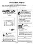
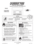
Cumberland Gap
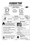
Non-Catalytic, Front/Side Load, Wood Heater
Owner’s Manual
Installation and Operation
Tested and
Listed by
Models:
Portland
Oregon USA
O-T L
US
C
OMNI-Test Laboratories, Inc.
CUMBGAP-MBK
CUMBGAP-PMH
CAUTION
• Important operating
and maintenance
instructions included.
• Read, understand and
follow these instructions
for safe installation and
operation.
• Leave this manual with
party responsible for
use and operation.
WARNING
WARNING
If the information in these
instructions is not followed
exactly, a fire may result causing
property damage, personal injury,
or death.
• Do not store or use gasoline or other
flammable vapors and liquids in the vicinity
of this or any other appliance.
• Do not overfire - If heater or chimney
connector glows, you are overfiring.
Overfiring will void your warranty.
• Comply with all minimum clearances to
combustibles as specified. Failure to comply
may cause house fire.
HOT SURFACES!
Glass and other surfaces are
hot during operation AND
cool down.
Hot glass will cause burns.
• Do not touch glass until it is cooled
• NEVER allow children to touch glass
• Keep children away
• CAREFULLY SUPERVISE children in same room
as fireplace.
• Alert children and adults to hazards of high
temperatures.
High temperatures may ignite clothing or other
flammable materials.
• Keep clothing, furniture, draperies and other
flammable materials away.
WARNING
Installation and service of this appliance should
be performed by qualified personnel. Hearth &
Home Technologies recommends NFI certified
professionals, or technicians supervised by an
NFI certified professional.
www.quadrafire.com
T
O
N RD
O A
D SC
I
D
DO NOT DISCARD THIS MANUAL
Fire Risk.
For use with solid wood fuel only.
Other fuels may overfire and generate
poisonous gases (i.e. carbon monoxide).
7006-188G
November 5, 2010
R
Cumberland Gap Wood Stove
and Welcome to the Quadra-Fire Family!
Hearth & Home Technologies welcomes you to our tradition of
excellence! In choosing a Quadra-Fire appliance, you have our
assurance of commitment to quality, durability, and performance.
This commitment begins with our research of the market, including
‘Voice of the Customer’ contacts, ensuring we make products that
will satisfy your needs. Our Research and Development facility
then employs the world’s most advanced technology to achieve
the optimum operation of our stoves, inserts and fireplaces. And
yet we are old-fashioned when it comes to craftsmanship. Each
unit is meticulously fabricated and surfaces are hand-finished for
lasting beauty and enjoyment. Our pledge to quality is completed
as each model undergoes a quality control inspection.
We wish you and your family many years of enjoyment in the
warmth and comfort of your hearth appliance. Thank you for
choosing Quadra-Fire.
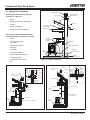
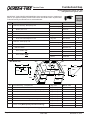
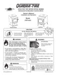
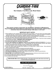
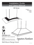
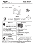
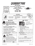
NOTE: Clearances may only be reduced by means
approved by the regulatory authority having jurisdiction
LABEL IS LOCATED ON THE BACK OF THE STOVE
CAUTION:
HOT WHILE IN OPERATION DO NOT TOUCH, KEEP CHILDREN AND CLOTHING AWAY. CONTACT MAY CAUSE SKIN BURNS. KEEP
FURNISHINGS AND OTHER COMBUSTIBLE MATERIAL FAR AWAY FROM THE APPLIANCE. SEE NAMEPLATE AND INSTRUCTIONS.
R
Tested and
Listed by
Portland
Oregon USA
O-T L
C
Cumberland Gap
US
OMNI-Test Laboratories, Inc.
TESTED TO:
UL 1482, UL737, ULC S627-00.
Report: #061-S-55-2
LISTED ROOM HEATER, SOLID FUEL TYPE. ALSO FOR
USE IN MOBILE HOMES. (UM) 84-HUD . "For Use with
Solid Wood Fuel Only"
PREVENT HOUSE FIRES
007
SERIAL NO.
Serial Number
VENT SPECIFICATIONS:
SINGLE WALL: Six inch (6") (152mm) diameter, minimum 24 MSG black or blued steel connector pipe, with a listed
factory-built UL103 HT Class "A" chimney, suitable for use with solid fuels, or a masonry chimney, and the referenced
clearances.
Install and use only in accordance with manufacturer's DOUBLE WALL: Six inch (6") (152mm) diameter, listed double wall air insulated connector pipe with listed
installation and operating instructions. Contact local building or
fire officials about restrictions and installation inspections in factory-built UL103 HT Class "A" chimney, or a masonry chimney and the referenced clearances.
your area. Do not obstruct the space beneath heater.
*In Canada must comply with Standard CAN/ULC-S629-M87 for the 650 degree Factory-built chimneys.
WARNING - For Mobile Homes: Do not install in a sleeping
room. An outside combustion air inlet must be provided and MOBILE HOME: Use double wall pipe by Dura-Vent DVL, Selkirk Metalbestos DS or Security DL double wall
unrestricted while unit is in use. The structural integrity of the connector pipe. Must be equipped with a spark arrestor. Apply double wall clearances below when installing unit.
mobile home floor, ceiling and walls must be maintained. The
stove needs to be properly grounded to the frame of the mobile
MINIMUM CLEARANCES TO COMBUSTIBLE MATERIALS: In Inches & (Millimeters)
home. Components required for mobile home installation:
NOTE: All "A" , "C" and "F" Dimensions are to the inside diameter of the flue collar.
Outside Air Kit, Part Number 831-1780.
A
B
C1
C2*
D1
D2*
E1
E2*
F1
F2*
G
H
Refer to manufacturer's instructions and local codes for TOP VENT VERTICAL
precautions required for passing chimney through a
13(330) 11.5(292) 27(686) 27(686) 18(457) 18 457) 16.5(419) 16.5(419) 20(508) 20(508) 56.5(1435) N/A
Single Wall-USA
combustible wall or ceiling and maximum offsets.
Inspect and clean chimney frequently - Under Certain Conditions of Single Wall-Canada 13(330) 11.5(292) 27(686) 27(686) 18(457) 18(457) 16.5(419) 18(457) 20(508) 21.5(546) 56.5(1435) N/A
Use, Creosote Buildup May Occur Rapidly.
12(305) 10.5(267) 25(635) 26(660) 15(381) 16(406) 11(279) 16(406) 14(356) 19(483) 56.5(1435) N/A
Do not connect this unit to a chimney serving another appliance. Double Wall-USA
Optional Components:Optional Blower, Part 831-1701.
Double Wall-Canada 12(305) 10.5(267) 25(635) 28(711) 15(381) 18(457) 11(279) 18(457) 14(356) 21(533) 56.5(1435) N/A
Electrical Rating: 115 VAC, 1.2 Amps, 60 Hz.
Route power cord away from unit. Do not route cord under or
in front of appliance.
HORIZONTAL WITH MINIMUM 2FT (609mm) VERTICAL OFF STOVE TOP
DANGER: Risk of electrical shock. Disconnect power supply
before servicing.
Single Wall-USA
13.5(343) 12(305) 27(686) 27(686) 17(432) 17(432) N/A
N/A
N/A
N/A 42.5(1080) 10.5(267)
Replace glass only with 5mm ceramic available from your dealer.
N/A
N/A
N/A 42.5(1080) 10.5(267)
Do not use grate or elevate fire. Build wood fire directly on firebrick. Single Wall-Canada 13.5(343) 12(305) 27(686) 28(711) 17(432) 18(457) N/A
Do not overfire - if heater or chimney connector glows, you are Double Wall-USA
11(279) 9.5(241) 27(686) 27(686) 17(432) 17(457) N/A
N/A
N/A
N/A 39(991) 8(203)
overfiring.
N/A
N/A
N/A
39(991) 8(203)
Operate only with the fuel loading door closed. Open only to Double Wall-Canada 11(279) 9.5(241) 27(686) 28(686) 17(432) 18(457) N/A
add fuel to the fire.
Optional Fire Screen Part SCR-7006 can only be used in full
vertical installations.
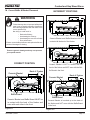
SEE MANUAL FOR OTHER CONFIGURATIONS
S
M
A
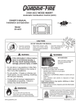
FLOOR PROTECTION*:
Both fuel loading doors accessible Side fuel loading door locked shut
Floor protector must be 1/2"
8"(200mm)
minimum thickness ("k" value =
0.84, R value = 0.59)
non-combustible material or
39-1/8"
equivalent, extending beneath
(994mm)
36-11/16"
Minimum
(932mm)
heater and to front/sides/rear as
Minimum
Minimum 16"
8"
8"
indicated on the diagram.
from
(200mm)
16" (406mm) from fuel (200mm)
fuel loading
Exception: Non-combustible floor
loading door
door
USA
USA
protections must extend beneath
44-7/8"(1140mm) Minimum
34-5/8"(879mm) Minimum
the flue pipe when installed with
horizontal venting and extend 2" *In Canada: Must be minimum 18"(450mm) in front of both fuel loading
doors and 8" (200mm) on both sides and back.
(51mm) beyond each side.
Fuel loading doors
Side
Front
B
P
L
1445 N. Highway, Colville, WA 99114
www.quadrafire.com
Page 2
2010 2011 2012 Jan. Feb. Mar. Apr.
E1
C2
Non-fuel
door side
H
F1
G
F2
D1
Non-fuel
door side
D2
Fuel Door
side
May June July Aug. Sept. Oct. Nov. Dec.
DO NOT REMOVE THIS LABEL
Testing Lab &
Report Number
C1
(406mm)
Mfg by
E
A
Front Fuel
loading door
Model Name
Made in U.S.A with US and Imported Parts.
7006-188G
E2
Fuel door
side
U.S. ENVIRONMENTAL PROTECTION AGENCY Certified to comply with July 1990 particulate emission
standards.
Mfg Date
7006-186G
November 5, 2010
R
Cumberland Gap Wood Stove
Safety Alert Key:
•
DANGER! Indicates a hazardous situation which, if not avoided will result in death or serious injury.
•
WARNING! Indicates a hazardous situation which, if not avoided could result in death or serious injury.
•
CAUTION! Indicates a hazardous situation which, if not avoided, could result in minor or moderate injury.
•
NOTICE: Indicates practices which may cause damage to the fireplace or to property.
TABLE OF CONTENTS
Section 1: Listing and Code Approvals
A.
B.
C.
D.
Section 6: Mobile Home ...............................23
Appliance Certifications ......................4
Mobile Home Approved ......................4
Glass Specifications ............................4
BTU & Efficiency Specifications ..........4
Section 7: Appliance Set-Up
A. Door Handle Assembly .......................24
B. Blower Speed Adjustment ..................24
Section 2: Getting Started
Section 8: Operating Instructions
A. Design, Installation & Location
Considerations ....................................5
B. Fire Safety ..........................................5
C. Negative Pressure ..............................6
D. Flue Draft Considerations ...................7
E. Venting Systems .................................7
F. Tools and Supplies Needed................7
G. Inspect Appliance & Components
and Pre-Burn Check List.....................7
H. Typical Stove System .........................8
A.
B.
C.
D.
E.
F.
G.
H
I.
J.
K.
L.
M.
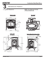
Section 3: Dimensions & Clearances
A. Appliance Dimensions ........................9
B. Clearances to Combustibles ...............10
Section 4: Installation Consideration
A.
B.
C.
D.
E.
F.
G.
H.
Hearth Requirements .........................11-12
Calculating Alternate Floor Protection
Material...............................................12
Reversible Flue Collar & Horizontal
Flue Heat Shield .................................13
Baffle Diverter.....................................14-15
Leg Leveling System ..........................16
Side Fuel Loading Door Locking
Mechanism .........................................16
Outside Air..........................................17
Optional Blower Installation ................17
Section 9: Maintaining & Servicing Appliance
A.
B.
C.
D.
E.
F.
Section 11: Reference Material
Venting Components ..........................18
Chimney Systems ...............................18-21
Installing Chimney Components .........21
Chimney Termination Requirements ..22
2-10-3 Rule ..........................................22
November 5, 2010
General Maintenance & Cleaning .......32-33
Appliance Inspection - Routine ...........34
Firebrick Inspection & Replacement ...34
Glass Replacement .............................34
Baffle Removal & Installation ..............35
Quick Reference Maintenance Guide .36
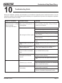
Section 10: Troubleshooting ........................37
Section 5: Chimney Requirements
A.
B.
C.
D.
E.
Overfiring Your Appliance ...................25
Wood Selection & Storage ..................25-26
Burning Process ..................................26-27
Combustible / Non-Combustible
Materials .............................................27
Air Controls .........................................27
Heat Output Settings ...........................28
Burn Rates ..........................................28
Building A Fire .....................................28
Blower Operating Instructions .............29
Opacity (Smoke) .................................29
Clear Space ........................................30
Frequently Asked Questions ...............30
Correct Baffle & Blanket Position ........31
7006-188G
A.
B.
C.
D.
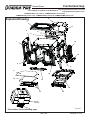
Exploded Drawings .............................38
Service Parts & Accessories...............39-41
Warranty Policy...................................42-43
Contact Information .............................44
Page 3
R
Cumberland Gap Wood Stove
1
Listing and Code Approvals
D. BTU & Efficiency Specifications
A. Appliance Certification
Model:
Cumberland Gap
Laboratory:
OMNI Test Laboratories, Inc.
Report No & Date: 061-S-55-2
EPA Certified:
3.44 grams per hour
Efficiency:
79.3%
BTU Output:
11,200 to 44,300
Type:
Listed Room Heater, Solid Fuel Type
Heating Capacity:
Standard:
UL1482, UL737, ULC S627-00
and (UM) 84-HUD, Mobile Home
Approved.
1,940 to 3,350 sq ft
depending on climate zone
Vent Size:
6 inches
Firebox Size:
2.39 cubic feet
Max Wood Length:
20 inches
Fuel:
Cord Wood
Shipping Weight:
462 lbs
NOTE: This installation must conform with local codes. In the
absence of local codes you must comply with the UL1482, UL737,
(UM) 84-HUD and NPFA211 in the U.S.A. and the ULC S627-00
and CAN/CSA-B365 Installation Codes in Canada.
WARNING
The Quadra-Fire Yosemite Wood Stove meets the U.S.
Environmental Protection Agency’s 1990 particulate emission standards.
B. Mobile Home Approved
• This appliance is approved for mobile home installations when not installed in a sleeping room and when
an outside combustion air inlet is provided.
• The structural integrity of the mobile home floor, ceiling, and walls must be maintained.
• The appliance must be properly grounded to the frame
of the mobile home with #8 copper ground wire, and
use only listed double-wall connector pipe.
• Outside Air Kit, part 831-1780 must be installed in a
mobile home installation.
Fire Risk.
•
•
•
•
•
•
•
Hearth & Home Technologies disclaims any
responsibility for, and the warranty will be
voided by, the following actions:
Installation and use of any damaged appliance.
Modification of the appliance.
Installation other than as instructed by Hearth & Home
Technologies.
Installation and/or use of any component part not
approved by Hearth & Home Technologies.
Operating appliance without fully assembling all
components.
Operating appliance without legs attached (if supplied
with unit).
Do NOT Overfire - If appliance or chimney connector
glows, you are overfiring.
Any such action that may cause a fire hazard.
C. Glass Specifications
This stove is equipped with 5mm ceramic glass. Replace
glass only with 5mm ceramic glass. Please contact your
dealer for replacement glass.
Quadra-Fire is a registered trademark of Hearth & Home
Technologies.
Page 4
Improper installation, adjustment, alteration, service or
maintenance can cause injury or property damage.
For assistance or additional information, consult a qualified
installer, service agency or your dealer.
NOTE: Hearth & Home Technologies, manufacturer of
this appliance, reserves the right to alter its products,
their specifications and/or price without notice.
7006-188G
November 5, 2010
R
Cumberland Gap Wood Stove
2
Getting Started
A. Design, Installation & Location Considerations
Consideration must be given to:
•
•
•
•
Safety
Convenience
Traffic flow
Chimney and chimney connector required
It is a good idea to plan your installation on paper, using exact
measurements for clearances and floor protection, before
actually beginning the installation. If you are not using an
existing chimney, place the appliance where there will be a
clear passage for a factory-built listed chimney through the
ceiling and roof.
We recommend that a qualified building inspector and your
insurance company representative review your plans before
and after installation
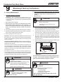
B. Fire Safety
To provide reasonable fire safety, the following should be
given serious consideration:
1.
Install at least one smoke detector on each floor of
your home to ensure your safety. They should be
located away from the heating appliance and close
to the sleeping areas. Follow the smoke detector
manufacturer’s placement and installation instructions,
and be sure to maintain regularly.
2.
A conveniently located Class A fire extinguisher to
contend with small fires resulting from burning embers.
3.
A practiced evacuation plan, consisting of at least two
escape routes.
4.
A plan to deal with a chimney fire as follows:
In the event of a chimney fire:
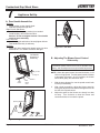
If this appliance is in an area where children may be near it
is recommended that you purchase a decorative barrier to go
in front of the appliance. Remember to always keep children
away while it is operating and do not let anyone operate
this appliance unless they are familiar with these operating
instructions.
a
b.
Evacuate the house immediately
Notify fire department
WARNING
Fire Risk.
CAUTION
Check building codes prior to installation.
• Installation MUST comply with local, regional, state and
national codes and regulations.
• Consult insurance carrier, local building, fire officials or
authorities having jurisdiction about restrictions, installation
inspection, and permits.
•
•
•
•
•
•
WARNING
•
Asphyxiation Risk.
• DO NOT CONNECT THIS UNIT TO A CHIMNEY FLUE SERVICING ANOTHER APPLIANCE.
• DO NOT CONNECT TO ANY AIR DISTRIBUTION DUCT OR SYSTEM.
May allow flue gases to enter the house.
Hearth & Home Technologies disclaims any
responsibility for, and the warranty will be
voided by, the following actions:
Installation and use of any damaged appliance.
Modification of the appliance.
Installation other than as instructed by Hearth & Home
Technologies.
Installation and/or use of any component part not
approved by Hearth & Home Technologies.
Operating appliance without fully assembling all
components.
Operating appliance without legs attached (if supplied
with unit).
Do NOT Overfire - If appliance or chimney connector
glows, you are overfiring.
Any such action that may cause a fire hazard.
WARNING
Fire Risk.
November 5, 2010
7006-188G
•
Do not operate appliance before reading and
understanding operating instructions.
•
Failure to operate appliance properly may
cause a house fire.
Page 5
R
Cumberland Gap Wood Stove
C. Negative Pressure
Draft is the pressure difference needed to vent appliances
successfully. Considerations for successful draft include:
•
Preventing negative pressure
•
Location of appliance and chimney
To minimize the affects of negative air pressure the following must be considered:
Negative pressure results from the imbalance of air available for the stove to operate properly. Causes for this imbalance include:
•
Exhaust fans (kitchen, bath) etc.)
•
Range hoods
•
Combustion air requirements for furnaces, water
heaters and other combustion appliances
•
Clothes dryers
•
Location of return-air vents to furnace or air conditioning
•
Imbalances of HVAC air handling system
•
Upper level air leaks
•
Install the outside air kit. Install the intake on the
side of the house towards prevailing winds during
the heating season.
•
Ensure adequate outdoor air is supplied for combustion appliances and exhaust equipment.
•
Ensure furnace and air conditioning return vents are
not located in the immediate vicinity of the appliance,
•
Avoid installing the appliance near doors, walkways
or small isolated spaces.
•
Recessed lighting should be of “sealed can” design;
attic hatches weather stripped or sealed; and attic
mounted ductwork and air handler joints and seams
taped or sealed.
WARNING
Asphyxiation Risk.
•
Recessed lighting
•
Attic hatch opening
•
Duct leaks
• Negative pressure can cause spillage of
combustion fumes, soot and carbon monoxide.
• Appliance needs to draft properly for
safety.
Recommended Location:
• Above peak
Recommended Location:
• Above peak
• Inside heated space
Marginal Location:
• Wind loading possible
Marginal Location:
• Below peak
Location NOT recommended:
• Not the highest point of the roof
• Wind loading possible
Recommended:
• Insulated exterior chase
in cooler climates
Location NOT recommended:
• Too close to tree
• Below adjacent structure
• Lower roof line
• Avoid outside wall
Windward
Leeward
Recommended:
Outside Air Intake
on windward side
Multi-level Roofs
NOT recommended:
Outside Air Intake
on leeward side
Figure 6.1
Page 6
7006-188G
November 5, 2010
R
Cumberland Gap Wood Stove
D. Flue Draft Considerations
F. Tools And Supplies Needed
Location of the appliance and chimney will affect performance. As shown in Figure 6.1 on page 6 the chimney
should:
Before beginning the installation be sure that the following
tools and building supplies are available.
•
Be installed through the warm space enclosed by the
building envelope. This helps to produce more draft,
especially during lighting and die down of the fire.
•
Penetrate the highest part of the roof. This minimizes
the affects of wind turbulence and down drafts.
•
Consider the appliance location in order to avoid
floor and ceiling attic joists and rafters.
Exterior conditions such as roof line, surrounding trees,
prevailing winds and nearby hills can influence stove
performance. Your local dealer is the expert in your geographic
area and can usually make suggestions or discover solutions
that will easily correct your flue problem.
To be sure that your appliance burns properly, the chimney
draft (static pressure) should be approximately -.04 inch water
column (W.C.) during a low burn and -.10 inch W.C. during a
high burn, measured 6 inches (152mm) above the top of the
appliance after one hour of operation at each burn setting.
NOTE: These are guidelines only, and may vary somewhat
for individual installations.
E. Venting Systems
The venting system consists of a chimney connector (also
known as stove pipe) and a chimney. These get extremely
hot during use. Temperatures inside the chimney may
exceed 2000F (1100C) in the event of a creosote fire. To
protect against the possibility of a house fire, the chimney
connector and chimney must be properly installed and
maintained. An approved thimble must be used when a
connection is made through a combustible wall to a chimney.
A chimney support package must be used when a connection
is made through the ceiling to a prefabricated chimney.
These accessories are absolutely necessary to provide
safe clearances to combustible wall and ceiling material.
Follow venting manufacturer’s clearances when installing
venting system.
Reciprocating saw
Pliers
Hammer
Phillips Head Screwdriver
Flat Blade Screwdriver
Plumb Line
Level
Tape Measure
Framing Material
G. Inspect Appliance & Components and
Pre-Burn Check List
1.
Place the appliance in a location near the final
installation area and follow the procedures below:
2.
Open the appliance and remove all the parts and
articles packed inside the Component Pack. Inspect
all the parts and glass for shipping damage. Contact
your dealer if any irregularities are noticed.
3.
All safety warnings have been read and followed.
4.
This Owner’s Manual has been read.
5.
Floor protection requirements have been met.
6.
Venting is properly installed.
7.
The proper clearances from the appliance and
chimney to combustible materials have been met.
8.
The masonry chimney is inspected by a professional
and is clean, or the factory built metal chimney is
installed according to the manufacturer’s instructions and clearances.
9.
The chimney meets the required minimum height.
10.
All labels have been removed from the glass door.
11.
A power outlet is available nearby if installing
optional blower assembly.
WARNING
WARNING
Asphyxiation Risk.
• DO NOT CONNECT THIS UNIT TO A CHIMNEY FLUE SERVICING ANOTHER APPLIANCE.
• DO NOT CONNECT TO ANY AIR DISTRIBUTION DUCT OR SYSTEM.
May allow flue gases to enter the house.
November 5, 2010
Non-Combustible Sealant
Material
Gloves
Framing Square
Electric Drill & Bits (1/4”)
Safety Glasses
1/2 in. - 3/4 in. length, #6 or
#8 self drilling screws (need 3
per pipe section connection)
7006-188G
Fire Risk.
Inspect appliance and components for damage.
Damaged parts may impair safe operation.
• Do NOT install damaged components.
• Do NOT install incomplete components.
• Do NOT install substitute components.
Report damaged parts to dealer.
Page 7
R
Cumberland Gap Wood Stove
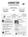
H. Typical Stove Systems
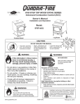
Spark Arrestor Cap
Stove system with masonry chimney
consists of: Figure 8.1
Fireclay Flue Liner
With Air Space
Concrete Cap
• Stove
Rafter
• Chimney Connector (stove pipe)
Flashing
• Thimble
1 in (25mm) Clearance
With Firestop
• Masonry Chimney
Ceiling Joist
• Hearth Pad Floor Protection
Eave
Combustible Wall
Stove system with prefabricated metal
chimney consists of: Figures 8.2 and 8.3
• Stove
Thimble,
12 in (305mm)
Of Brick
• Chimney Connector
(stove pipe)
Sheathing
• Thimble (for exterior
chimney)
Outside Air Rear Vent
• Firestops
Outside Air
Termination Cap
Floor
Protector
• Insulations Shields
• Storm Collar and Flashing
Airtight
Cleanout Door
• Termination Cap
Figure 8.1 Masonry Chimney
• Hearth Pad Floor Protection
Combustible Outside Wall
Listed
Chimney Pipe
Maintain 2" (51mm)
Clearance
2" (51mm)
Clearance
Chimney
Connector
Storm Collar
Insulated "T"
Ceiling
Support
Chimney
Connector
Wall Support
Attic
Insulation
Shield
Specified
Clearance
Flashing
To Stove
Trim Collar
on Inside
Wall
Combustible
Ceiling
Joists
Listed Chimney
Listed Cap
Maintain 2" (51mm)
Clearance Through Eave
Listed
Chimney
Listed Cap
Listed Chimney
To Stove
Wall Spacer on
Outside Wall
Flashing
Combustible
Ceiling
Ceiling Support
*
Chimney
Connector
Insulated "T"
Chimney
Connector
Combustible Wall
*
*
*
Floor
Protector
*Refer to Clearances
to Combustibles
Floor
Protector
*Refer to Clearances to Combustibles
Figure 8.2 Exterior Prefabricated Chimney
Page 8
*
Combustible Wall
Figure 8.3 Interior Prefabricated Chimney
7006-188G
November 5, 2010
R
Cumberland Gap Wood Stove
3
Dimensions and Clearances
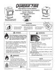
NOTE: Flue Collar size is 6 inch
(152mm) diameter (ID)
A. Appliance Dimensions
FRONT VIEW
TOP VIEW
16.0"
(406mm)
CL
26-7/8"
(683mm)
C
L
16-11/16"
(424mm)
12-3/16"
(310mm)
18-1/8"
(460mm)
27-1/4"
(692mm)
20-3/16"
(513mm)
2-9/16"
(65mm)
SIDE VIEW
SIDE VIEW WITH FUEL DOOR
22-7/8"
(581mm)
4-1/2"
(114mm)
20-3/16" (513mm)
16-5/8" (422mm)
C
L
CL
28-3/16"
(716mm)
27-11/16"
(703mm)
25.0"
(635mm)
27-11/16"
(703mm)
6-9/16"
(167mm)
4-3/16"
(106mm)
17-3/4"(451mm)
27-15/16"(710mm)
8-11/16"
(221mm)
November 5, 2010
7006-188G
Page 9
R
Cumberland Gap Wood Stove
B. Clearances To Combustibles (UL And ULC)
B
E1
A
F1
Non-fuel
door side
C2
H
G (Ceiling)
G (Ceiling)
F2
C1
D2
D1
Non-fuel
door side
E2
Fuel door
side
Fuel Door
side
Max Mantel Depth
10" (254mm)
G (Mantel)
IF SIDE FUEL LOADING DOOR IS NOT USED:
• Must remain in the locked position at all times
• Use clearances for non-fuel side door for both sides
MINIMUM CLEARANCES TO COMBUSTIBLE MATERIALS: In Inches & (Millimeters)
NOTE: All "A" , "C" and "F" Dimensions are to the inside diameter of the flue collar.
TOP VENT VERTICAL
A
B
C1
C2
D1
D2
Single Wall-USA
Single Wall-Canada
Double Wall-USA
Double Wall-Canada
13(330)
13(330)
12(305)
12(305)
11.5(292)
11.5(292)
10.5(267)
10.5(267)
27(686)
27(686)
25(635)
25(635)
27(686)
27(686)
26(660)
28(711)
18(457)
18(457)
15(381)
15(381)
18(457)
18(457)
16(406)
18(457)
E1
E2
16.5(419) 16.5(419)
16.5(419) 18(457)
11(279) 16(406)
11(279) 18(457)
F1
20(508)
20(508)
14(356)
14(356)
F2
20(508)
21.5(546)
19(483)
21(533)
G
56.5(1435)
56.5(1435)
56.5(1435)
56.5(1435)
H
N/A
N/A
N/A
N/A
HORIZONTAL WITH MINIMUM 2FT (609mm) VERTICAL OFF STOVE TOP. (Note: Horizontal must be with 2ft (609mm) vertical
and NOT directy off stove).
Single Wall-USA
13.5(343) 12(305) 27(686)
Single Wall-Canada 13.5(343) 12(305) 27(686)
Double Wall-USA
11(279) 9.5(241) 27(686)
Double Wall-Canada 11(279) 9.5(241) 27(686)
27(686)
28(711)
27(686)
28(711)
17(432)
17(432)
17(432)
17(432)
17(432)
18(457)
17(432)
18(457)
N/A
N/A
N/A
N/A
N/A
N/A
N/A
N/A
N/A
N/A
N/A
N/A
N/A
N/A
N/A
N/A
42.5(1080) 10.5(267)
42.5(1080) 10.5(267)
39(991)
8(203)
39(991)
8(203)
ALCOVE - Six inch (6") (152mm) diameter listed DOUBLE WALL air insulated connector pipe with UL103 HT listed factory-built Class "A"
chimney, or a masonry chimney. (Mobile Home must be equipped with a spark arrestor.)
Max Depth
Min Width
Min Height
Front Door
48(1219)
55(1397)
72(1829)
Side Door-USA
48(1219)
57(1448)
72(1829)
Side Door-Canada
48(1219)
61(1549)
72(1829)
Double Wall-USA
12(305) 10.5(267) 25(635) 26(660) 15(381) 16(406) N/A
N/A
N/A
N/A
44(1118)
N/A
Double Wall-Canada 12(305) 10.5(267) 25(635) 28(711) 15(381) 18(457) N/A N/A
N/A
N/A
44(1118)
N/A
REAR VENT INSTALLATIONS IN A MASONRY FIREPLACE OR THROUGH THE WALL . HORIZONTAL FLUE HEAT SHIELD, PART HTSHLD-7006,
REQUIRED ON REAR VENT INSTALLATIONS: Six inch (6") (152mm) diameter listed double wall air insulated connector pipe with UL103 HT listed
factory-built Class "A" chimney, or a masonry chimney. (Mobile Home must be equipped with a spark arrestor). Additional specifications include a
MAXIMUM 10" (254mm) MANTEL WIDTH and the following clearances.
Double Wall-USA
N/A
12(305) 27(686) 27(686) 17.5(445) 17.5(445) N/A N/A
N/A
N/A 39(991) ceiling N/A
12(305) 27(686) 27.5(699) 17.5(445) 18(457) N/A N/A
N/A
N/A 39(991) ceiling N/A
Double Wall-Canada N/A
USA or Canada -Single or Double Wall Pipe: 31(787) mantel N/A
USA or Canada -Single or Double Wall Pipe: 24(610) mantel* N/A
*with metal shield spaced 1" (25mm) away from bottom mantel surface
HEARTH MOUNT - SIDE DOOR MUST BE LOCKED CLOSED
Single Wall-USA
Single Wall-Canada
18(457) 10(254) 22(559)
18(457) 10(254) 22(559)
31(787)
31(787)
N/A
N/A
N/A
N/A
N/A
N/A
N/A
N/A
N/A
N/A
N/A
N/A
N/A
N/A
N/A
N/A
NOTE: Optional Fire Screen, Part SCR-7006, can only be used in FULL Vertical installations
Page 10
7006-188G
November 5, 2010
See page 6 for stove clearances
R
Cumberland Gap Wood Stove
4
Installation Considerations
A. Hearth Protection Requirements
FLOOR PROTECTOR: Floor protector must be noncombustible material, extending beneath heater and to the
front/sides/rear as indicated. The floor must be a minimum
of 1/2 inch (26mm) thickness ("k" value = 0.84, R value =
0.59) non-combustible or otherwise adequately protected
from radiant heat given off by the unit and from sparks and
falling embers. A layer of thin brick or ceramic tile over a
combustible floor is not sufficient. See Alternate Floor Protection on page 12.
In USA installations, it is necessary to install a noncombustible floor protector at least 16 inches in front and 8
inches to both sides of the fuel loading doors. See *exception below.
In Canada, similar floor protection must be provided 18
inches (450mm) in front and 8 inches (200mm) from the
sides and rear of the stove. See *exception below.
*EXCEPTION: Non-combustible floor protections must
extend beneath the flue pipe when installed with horizontal
venting and extend 2 inches (51mm) beyond each side.
SIDE FUEL DOOR LOCKED SHUT
200mm (8")
Front Fuel
loading door
39-1/8"
(994mm)
Minimum
16" (406mm) from
fuel loading door
200mm
(8")
200mm
(8")
1371mm
(54")
Minimum
8"
(200mm)
USA
450mm (18")
34-5/8"(879mm)
Minimum
CANADA
1089mm (42-7/8") Minimum
Figure 11.1
Figure 11.2
BOTH FUEL DOORS ACCESSIBLE
Figure 11.3
November 5, 2010
Figure 11.4
7006-188G
Page 11
R
Cumberland Gap Wood Stove
A. Hearth Protection Requirements (Cont'd)
B. Calculating Alternate Floor Protection Material
SIDE FUEL DOOR LOCKED SHUT - USA ONLY
Thermal Conductivity: k value
52"
e
o
lc
a
on
ti
op
o
co ptio
ve na
ra l
ge
ag
r
ve
The k value indicates the amount of heat (in BTU’s) that will flow
in 1 hour through 1 square foot of a uniform material 1 inch thick
for each degree (F) of temperature difference from one side of
the material to the other. The LOWER the k factor means less
heat is being conducted through the non-combustible material
to the combustible material beneath it. The k value of a material must be equal or smaller then the required k value to be
acceptable.
(BTU) (inch)
(foot2 (hour) (oF)
"
/8
5
4-
3
e
ra
g
ve
co
"
ire
/8
qu
30
-3
re
38
Thermal Resistance: R value
d
8”
/
-5
8"
o
co ptio
ve na
ra l
ge
16
"
8"
l
r
ue oo
tf gd
n
o n
Fr adi
lo
52"
Figure 12.1
BOTH FUEL DOORS ACCESSIBLE - USA ONLY
The R value is a measure of a material’s resisteance to heat
transfer. R value is convenient when more than one material
is used since you can add the R values together, whereas you
can not do this for k value. The HIGHER the R factor means
less heat is being conducted through the non-combustible material to the combustible material beneath it. The R value of a
material must be equal or larger then the required R value to be
acceptable.
Converting k to R:
48-7/16"
optional coverage
53-7/16"
Divide 1 by k and multiply the results times the thickness in inches of the material.
R = 1/k x inches of thickness
Converting R to k:
44-3/4"
Divide the inches of thickness by R.
optional
coverage
optional
coverage
Fuel loading
door
38-5/8"
8"
11-1/8"
16"
k = inches of thickness/R
Calculatons:
Example: Floor protection requires k value of 0.84 and 3/4 inch
thick.
Alternative material has a k value of 0.6 and is 3/4 inch thick.
25-3/4"
16"
required coverage
Divide 0.6 by .75 = k value of 0.80. This k value is smaller than
0.84 and therefore is acceptable.
18-5/8"
Figure 12.2
HORIZONTAL VENTING
NOTE:
• Illustrations and photos reflect typical
Floor protection must extend
length of flue and 2 inches
(51mm) beyond each side of
pipe (shaded area)
installations and are FOR DESIGN
PURPOSES ONLY.
•
Illustrations/diagrams are not drawn to
scale.
•
Actual installation may vary due to
individual design preference
•
Hearth & Home Technologies reserves
the right to alter its products.
Page 12
USA - Required
CANADA - Recommended
7006-188G
November 5, 2010
R
Cumberland Gap Wood Stove
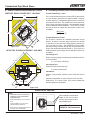
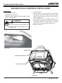
B. Reversible Flue Collar and Horizontal
Flue Heat Shield
Remove cast top
Tools Required: Phillips head screwdriver; 3/8" and 7/16"
wrench
Remove bolts and
rotate flue collar
The flue collar is reversible for either a top or rear venting
installation. The appliance is shipped with the flue collar in
the top vent position.
Discard heat
shield
REQUIRED PARTS FOR REAR INSTALLATION:
•
Baffle Diverter: Shipped with appliance located inside
firebox
•
Horizontal Flue Heat Shield, Part HTSHLD-7006: Not supplied, must be purchased from your local authorized dealer
Rear Heat
Shield
Remove 4 screws and set
rear shield & screws aside
Converting Collar For Rear Vent Installation
and
Installing Required Horizontal Flue Shield
Figure 13.1
1.
Lift off cast top. Remove 4 Phillips head screws from the
heat shield. Discard heat shield and save the screws.
Figure 13.1.
2.
Remove 4 Phillips head screws from the rear shield, 2 on
each side, lift shield off and set aside. Figure 13.1.
3.
Remove 1 bolt from each side of the flue collar and retrieve
nuts attached to bolts. Use 3/8" and 7/16" wrenches. Figure
13.1.
4.
Turn vent to horizontal position. Inspect sealant to ensure
a leak free application. Re-attach bolts. Figure 13.1.
Secure
Horizontal Flue
Heat Shield
5. Re-attach the rear heat shield.
6. Attach required accessory Horizontal Flue Shield with 2
of the screws removed in Step #1 and secure in place.
7. Follow instructions for placing the Baffle Diverter on
pages 14 & 15.
Figure 13.2
8. Place cast top on the unit. See Figure 13.3 for completed
view.
Figure 13.3 - Completed View
November 5, 2010
7006-188G
Page 13
R
Cumberland Gap Wood Stove
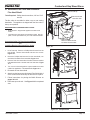
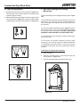
D. Baffle Diverter
REQUIRED ON ALL HORIZONTAL INSTALLATIONS
Baffle Diverter:
1. Open both doors.
•
Packed inside the firebox
•
Shipped flat from the factory.
•
Use the template on page 15 to bend the baffle diverter
into the proper position.
2. Hold the diverter in a vertical position with the straight
edge going in first and then rotate it to the inside of the
firebox as you slide the bent diverter over the ceramic
blanket . Figure 14.1.
Fire Risk.
3. Place in position as shown in Figure 14.2 below. The
front edge of the diverter will rest on the front edge of
the manifold chamber in a flush position. The back
edge will butt up against the back slanted corner.
Required on all rear horizontal installations.
4. Repeat for other side.
WARNING
Excessive smoke or flame spillage into the
room may occur.
Figure 14.1
Slanted corner
Ceramic Blanket
Straight end to the back
Manifold
chamber
Cut end to the front
Figure 14.2
Page 14
7006-188G
November 5, 2010
R
Cumberland Gap
Wood Stove
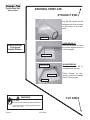
BENDING TEMPLATE
STRAIGHT END
Lay the flat diverter on the
template with the cut ends
at the bottom of the template.
Cut Ends
HAND BEND #1
Bend the diverter to match
the same degree bend as
in the template.
Baffle Diverter
is shipped
inside firebox.
Hand Bend #1
Hand bend #2
Straight End
HAND BEND #2
Bend the diverter 90° to
complete the process.
Place diverter on template to confirm the bends
match the template.
Cut Ends
WARNING
CUT ENDS
Fire Risk.
Required on all rear horizontal installations.
Excessive smoke or flame spillage into the
room may occur.
Page 15
7006-188G
R
Cumberland Gap Wood Stove
E. Leg Leveling System
1. Thread Allen bolts through nuts until flush. Figure 16.1.
The Allen bolts and nuts are included in the component pack
inside the appliance firebox.
2. Slide assembled nuts and bolts into slots on legs with the
nuts on the bottom. Figure 16.2. Use a 5/32 Allen wrench
to adjust legs up and down to desired level. Figure 16.3.
F. Side Fuel-Loading-Door Locking
Mechanism
The side fuel loading door is shipped locked in place. Figure
16.4
You must first decide where you are locating your stove and
determine if you meet the minimum required clearances
from combustibles for loading wood into the firebox from
the side door.
If you do not meet the clearances found on page10, leave the
door locked in place. If you unlock the door without meeting
the minimum required clearances YOU WILL VOID YOUR
WARRANTY AND ASSUME ALL RESPONSIBILITIES.
If you meet the minimum clearances, follow the instructions
to unlock the door.
Figure 16.1
If in the future you decide to relocate your stove, again
determine if you meet the mimimum required clearances
to combustibles in the new location. If you do not, you are
required to lock the door shut and it must remain locked at
all times.
Instructions To Unlock Side Fuel Door
1. Open front door.
Figure 16.2
2.. Using a 5-32 Allen wrench, remove the bolt from the
locking bracket. Figure 16.4.
3. Save the bracket and bolt for potential future use.
Figure 16.3 - Bolt fully extended
Figure 16.4
Page 16
7006-188G
November 5, 2010
R
Cumberland Gap Wood Stove
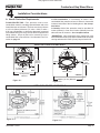
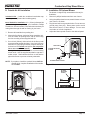
H. Installation Of Optional Blower
G. Outside Air Kit Installation
Included in Kit: 2 cable ties; oustide air termination cap;
mounting screws (Discard the remaining parts).
Items Needed for Installation: 4 in. (102mm) diameter flex
pipe in the length as required for your installation; Phillips
screwdriver; Silicone sealant; Drills and saws necessary for
cutting holes through the wall or flooring in your home.
1. Remove all materials from packing box.
1.
The blower is shipped fully assembled and ready for
installation.
Remove 3 phillips head screws from rear of stove.
2.
Using the phillips head screws, attach blower to lower
rear of stove, as shown.
3.
Plug blower cord into a grounded outlet. Do not remove
ground prong from plug. Route power cord to avoid
heat from the stove, or other damage. Do not route
cord under or in front of appliance.
4.
Adjust the blower speed control to the desired speed.
2. Mount the flex flange (with pipe fitting extending out),
over the intake air opening at the rear of stove using
the four mounting screws supplied with kit.
3. Cut a 4 inch (102mm) minimum hole in the floor or wall
to accommodate outside air piping. Use 4 inch (102mm)
metal flex or rigid piping to directly connect outside air
to the unit or into vented crawl space. (Do not put flex
into a non-vented crawl space).
REAR SHIELD
BLOWER MOUNTING
FLANGE
If using flex tubing attach cable ties to secure tubing
at both ends. Use the supplied termination cap with a
rodent screen. Seal between the floor or wall and the
pipe with silicone to prevent moisture penetration.
NOTE: If you plan to install the optional blower AND the
outside air kit, complete installation of the outside
air kit FIRST.
BLOWER SPEED CONTROL
Figure 17.2
BLOWER
MOUNTING
FLANGE
REAR
SHIELD
OUTSIDE AIR
TERMINATION CAP
(contains rodent screen)
Figure 17.3
OUTSIDE AIR
INTAKE
Figure 17.1
November 5, 2010
7006-188G
Page 17
R
Cumberland Gap Wood Stove
5
Chimney Requirements
A. Venting Components
B. Chimney Systems
Chimney Connector:
Prefabricated Metal Chimney
It is also known as flue pipe or stove pipe. The chimney
connector joins the stove to the chimney. It must be a 6 inch
(152mm) minimum diameter 24 gauge mild steel black or
26 gauge blued steel, or an approved air-insulated double
wall venting pipe.
Thimble:
A manufactured or site-constructed device installed in
combustible walls through which the chimney connector
passes to the chimney. It is intended to keep the walls
from igniting. Site constructed thimbles must meet
NFPA 211 Standards. Prefabricated must be suitable
for use with selected chimney and meet UL103 Type
HT Standards. Follow instructions provided by the
manufacturer for manufactured thimbles for masonry
chimney and prefabricated chimneys.
•
Must be minimum 6 inch (152mm) diameter (ID) high
temperature chimney listed to UL 103 HT (2100oF) or
ULC S629M.
•
Must use components required by the manufacturer for
installation.
•
Must maintain clearances required by the manufacturer
for installation.
•
Refer to manufacturers instructions for installation.
NOTE: In Canada when using a factory-built chimney it must
be safety listed, Type UL103 HT (2100oF) CLASS “A” or
conforming to CAN/ULC-S629M, STANDARD FOR 650oC
FACTORY-BUILT CHIMNEYS.
ADDITIONAL REQUIRED PARTS FOR REAR INSTALLATION:
Chimney:
•
The chimney can be new or existing, masonry or
prefabricated and must meet the following minimum
requirements specified in Section 5B.
Baffle Diverter: Shipped with appliance located inside
firebox
•
Horizontal Flue Heat Shield, Part HTSHLD-7006: Not supplied, must be purchased from your local authorized dealer
Combustible Outside Wall
Listed
Chimney Pipe
Maintain 2" (51mm)
Clearance
2" (51mm)
Clearance
Chimney
Connector
Storm Collar
Listed Chimney
To Stove
Attic
Insulation
Shield
Specified
Clearance
Insulated "T"
Ceiling
Support
Chimney
Connector
Wall Support
Trim Collar
on Inside
Wall
Combustible
Ceiling
Joists
Flashing
Listed Cap
Maintain 2" (51mm)
Clearance Through Eave
Listed
Chimney
Listed Cap
Listed Chimney
To Stove
Wall Spacer on
Outside Wall
Flashing
Combustible
Ceiling
Ceiling Support
*
Chimney
Connector
Insulated "T"
Chimney
Connector
Combustible Wall
*
*
*
Floor
Protector
*Refer to Clearances
to Combustibles
Floor
Protector
*Refer to Clearances to Combustibles
Figure 18.1 Prefabricated Exterior Chimney
Page 18
*
Combustible Wall
Figure 18.2 - Prefabricated Interior Chimney
7006-188G
November 5, 2010
R
Cumberland Gap Wood Stove
Thimble
C
L
Site constructed for masonry chimney installation:
ceiling
Components
• A minimum length of 12 inches [305mm] (longer for thicker
walls) of solid insulated factory-built chimney length constructed to UL 103 Type HT 6 inch (152mm) inside diameter. Chimney needs to extend a minimum of 2 inches
(51mm) from the interior wall and a minimum of 1 inch
(25mm) from the exterior wall.
• Wall spacer, trim collar and wall band to fit solid pack
chimney selected.
• Minimum 8 inch (203mm) diameter clay liner section (if
not already present in chimney) and refractory mortar.
Air Clearances
Wall
Minimum18.0”
NFPA 211
13.5” below ceiling to top
of opening
or top of opening is a min.of
4.5” below min.clearance
specified by connector mfg.
1.5 2x2 framing stud
2.0 min air clearance
1.0 min air clearance
4.5
1.5”
2.0”
1.0”
17.0” OD 14.0” ID 8.0”
1.0”
C
L
2.0”
1.5”
Center of Hole
Thimble
• Masonry chimney clearance must meet NFPA 211 minimum requirement of 2 inches (51mm) to sheet metal supports and combustibles.
Include depth
of hearth pad
• Minimum of 1 inch (25mm) clearance around the chimney
connector.
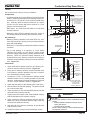
• Top of wall opening is a minimum of 13-1/2 inches
(343mm) from ceiling or 4-1/2 inches (114mm) below
minimum clearance specified by chimney connector manufacturer. NFPA 211 minimum vertical clearance of 18
inches (457mm) from chimney connector and ceiling or
minimum recommended by chimney connector manufacturer. Figure 19.1.
Figure 19.1
Fire Clay Flue
Liner
with Airspace
Instructions:
1. Open inside wall at proper height for the chimney connector to entry the masonry chimney. Figure 19.1
2. Entry hole to masonry chimney must be lined with an 8
inch (203mm) minimum diameter clay liner, or equivalent, secured with refractory mortar.
3. Construct a 17 inch x 17 inch (432mm x 432mm) outside
dimension frame from 2 x 2 framing lumber to fit into wall
opening. Inside opening of frame should be no less than
14 inch x 14 inch (356mm x 356mm). Figure 19.1.
4. Attach the wall spacer to the chimney side of the frame.
5. Nail the frame into the wall opening. The spacer should
be on the chimney side.
6. Insert the section of the solid insulated chimney into the
outer wall of the masonry chimney.
7. Tightly secure the length of the solid insulated chimney
with the wall band to the masonry chimney.
8. Insert a section of chimney connector into the chimney.
Make sure it does not protrude past the edge of the clay
chimney liner inside the chimney.
9. Seal the end of the chimney connector to the clay liner
with refractory mortar.
10. Install trim collar around the sold pack chimney section.
November 5, 2010
7006-188G
Masonry
Chimney
Trim Collar
Wall Spacer
Chimney Section
with 2 inch
(51mm)
Clearance to
Combustibles
Wall Band to
Secure Chimney
Section
Chimney
Connector
Wood Studs Used
for Framing - Spaced
2 inch (51mm)
clearance from
Masonry Chimney
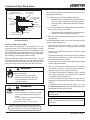
Figure 19.2 - Solid Pack Chimney with Metal Supports as a Thimble
WARNING
Fire Risk.
Do NOT pack insulation or other combustibles between
spacers.
• ALWAYS maintain specified clearances around
venting and spacers.
• Install spacers as specified.
Failure to keep insulation or other material away from
vent pipe may cause fire.
Page 19
R
Cumberland Gap Wood Stove
Masonry Chimney Liner
Min. Chimney Clearance to
Wall Spacer and
Combustibles - 2 inch (51mm)
For optimal performance, masonry chimneys used to vent
this appliance should be:
Min. Clearance
2 inch (51mm)
1. Lined with a 6 inch (152mm) stainless steel liner.
1 inch (25mm) Air
Space to Chimney
Section
Chimney Flue
Liner
Fireclay
Liner or
Equivalent
• Installations into a clay flue without a stainless steel
liner may reduce draw which affects performance,
cause the glass to darken and produce excessive
creosote.
Chimney
Connector
Chimney Section
2. It is recommended that a chimney with a larger diameter
than 6 inches (152mm) be relined.
Trim Collar
Wall Band
Wall Spacer
Masonry Chimney
Constructed to NFPA 211
• The oversized flue can cause poor performance and
contribute to the accumulation of creosote.
3. Have the chimney cleaned before the stove is installed
and operated.
Figure 20.1 - Solid Pack Chimney with Metal Supports
as a Thimble (Cont’d)
The following bullets list the more critical requirements for a
properly constructed chimney:
Chimney Height / Rise and Run
•
This product was designed for and tested on a 6 inch
(152mm) chimney, 12 to 14 feet (420-480cm) high, (includes
stove height) measured from the base of the appliance to the
top of the chimney (not including chimney cap). The further
your stack height or diameter varies from this configuration,
the possibility of performance problems exists.
The masonry wall of the chimney, if brick or modular
block, must be a minimum of 4 inches (102mm) nominal
thickness.
•
A chimney of rubble stone must be at least 12 inches
(305mm) thick.
Chimney height may need to be increased by 2 - 3% per
each 1000 feet above sea level. It is not recommended to
use offsets or elbows at altitudes above 4000 feet above sea
level or when there are other factors that affect flue draft.
•
• The chimney must have a fire clay flue liner (or equivalent)
with a minimum thickness of 5/8 inch (16mm) and must
be installed with refractory mortar.
An equivalent liner must be a listed chimney liner system
or other approved material.
• Since an oversized flue contributes to the accumulation
of creosote, the size of the flue should be checked to
determine that it is not too large for the insert.
WARNING
Fire Risk.
Inspection of Chimney:
• Chimney must be in good condition.
• Meets minimum standard of NFPA 211
• Factory-built chimney must be 6 inch
(152mm) UL103 HT.
• The chimney should also be checked to ensure it meets
the minimum standard of the National Fire Protection
Association (NFPA) Standard 211.
•
A chimney support package must be used when a
connection is made through the ceiling to a factory built
chimney.
•
An approved thimble and chimney support package
are absolutely necessary to provide safe clearances to
combustible wall and ceiling material.
WARNING
Asphyxiation Risk.
• DO NOT CONNECT THIS UNIT TO A CHIMNEY FLUE SERVICING ANOTHER APPLIANCE.
• DO NOT CONNECT TO ANY AIR DISTRIBUTION DUCT OR SYSTEM.
May allow flue gases to enter the house.
NOTICE: In Canada, the installation shall conform to
CAN/CSA-B365.
NOTICE: Check with your local building authorities
and/or consult the National Fire Protection Association
(NFPA 211).
NOTE: Optional Fire Screen, Part SCR-7006,
can only be used in FULL Vertical installations.
Page 20
7006-188G
November 5, 2010
R
Cumberland Gap Wood Stove
Masonry Chimney Liner (Cont'd)
C. Installing Chimney Components
Chimney Connector
Wood Stud 2 in.
(51mm)
Clearance from
chimney wall
Single wall connector or stove pipe.
Fireclay liner 5/8 in.
(16mm) Minimum
or Equivalent.
Header
This must be at least 24 gauge mild steel or 26 gauge blue
steel. The sections must be attached to the appliance and
to each other with the crimped (male) end pointing toward
the stove. All joints, including the connection at the flue
collar, should be secured with 3 sheet metal screws. Make
sure to follow the minimum clearances to combustibles.
Where passage through the wall, or partition of combustible
construction is desired in Canada, the installation shall
conform to CAN/CSA-B365.
Factory-built listed chimney connector (vented).
A listed connector (vented) must be used when installing
this unit in a mobile home. The listed connectors must
conform to each other to ensure a proper fit and seal.
Fireclay liner 5/8 in.
(16mm) Minimum
or Equivalent.
Sill support
Crimped
End
Toward
Stove
Thimble Assembly:
12 in. (305mm) of
brick separation
between clay liner
and combustibles.
Flue Gas
Direction
Secure pipe sections with a
minimum of 3 screws
Figure 21.2 Chimney Connector (Stove Pipe)
Figure 21.1
WARNING
Improper installation, adjustment, alteration, service or
maintenance can cause injury or property damage. Refer
to the owner’s information manual provided with this appliance. For assistance or additional information consult a
qualified installer, service agency or your dealer.
WARNING
Fire Risk.
Follow Chimney Connector Manufacturer’s
Instructions for Proper Installation.
ADDITIONAL REQUIRED PARTS FOR REAR INSTALLATION:
•
Baffle Diverter: Shipped with appliance located inside
firebox
•
Horizontal Flue Heat Shield, Part HTSHLD-7006: Not supplied, must be purchased from your local authorized dealer
ONLY use connector:
• Within the room, between appliance and ceiling or wall.
Connector shall NOT pass through:
• Attic or roof space
• Closet or similar concealed space
• Floor or ceiling
Maintain minimum clearances to combustibles
NOTE: Optional Fire Screen, Part SCR-7006,
can only be used in FULL Vertical installations.
November 5, 2010
7006-188G
Page 21
R
Cumberland Gap Wood Stove
D. Chimney Termination Requirements
NOTE:
• Chimney performance may vary.
• Trees, buildings, roof lines and wind conditions affect
performance.
• Chimney height may need adjustment if smoking or
overdraft occurs.
Follow manufacturer’s instructions for clearance, securing
flashing and terminating the chimney.
• Must have an approved and Listed cap
• Must not be located where it will become plugged
by snow or other material
•
Must terminate at least 3 feet (91cm) above the
roof and at least 2 feet (61cm) above any portion
of the roof within 10 feet (305cm).
•
Must be located away from trees or other structures
E. 2-10-3 Rule
These are safety requirements and are not meant to assure proper flue draft.
Less than 10 ft. (305cm)
2 ft. (61cm)
2 ft. (61cm)
3 ft. (91cm)
Minimum
10 ft. (305cm) To Nearest Roofline
3 ft. (91cm)
Minimum
Pitched Roof
Figure 22.1
10 ft. (305cm) or more
Less than 10 ft. (305cm)
Wall or Parapet
2 ft. (61cm)Minimum
3 ft. (91cm) Minimum
Figure 22.2
Page 22
3 ft. (91cm) Minimum
Flat Roof
7006-188G
November 5, 2010
R
Cumberland Gap Wood Stove
6
Mobile Home Installation
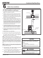
You must use a Quadra-Fire Outside Air Kit Part
831-1780 for installation in a mobile home.
Spark Arrestor Cap
1. An outside air inlet must be provided for combustion See
page 17 for installation information.
Storm Collar
2. Appliance must be secured to the mobile home structure
by bolting the pedestal through hearth pad and into floor.
Roof Flashing
3. Appliance must be grounded with #8 solid copper
grounding wire or equivalent and terminated at each end
with N.E.C. approved grounding device.
Joist Shield/Firestop
4. Appliance must be installed with an approved UL103 HT
ventilated chimney connector, UL103 HT chimney, and
terminal cap with spark arrestor. Never use a single wall
connector (stove pipe) in a mobile home installation. Use
only double-wall connector pipe, Dura-Vent DVL, Selkirk
metalbestos DS or Security DL double-wall connector or
any listed double-wall connector pipe.
Listed Chimney
5. In Canada, this appliance must be connected to a 6 inch
(152mm) factory-built chimney conforming to CAN/ULC629M, STANDARD FOR FACTORY BUILT CHIMNEYS.
6. Follow the chimney and chimney connector manufacturer’s
instructions when installing the flue system for use in a
mobile home.
Outside Air Kit
Connector
Floor Protector
7. Maintain clearance to combustibles.
8. Floor protection requirements must be followed precisely.
9. Use silicone to create an effective vapor barrier at
the location where the chimney or other component
penetrates to the exterior of the structure.
NOTE: Offsets from the vertical, not exceeding 45°, are
allowed per Section 905(a) of the Uniform Mechanical Code
(UMC). Offsets greater than 45° are considered horizontal
and are also allowed, providing the horizontal run does not
exceed 75% of the vertical height of the vent. Construction,
clearance and termination must be in compliance with the
UMC Table 9C. This installation must also comply with NFPA
211.
NOTE: Top sections of chimney must be removable to allow
maximum clearance of 13.5 feet (411cm) from ground level
for transportation purposes.
Outside Air Floor Vent
Figure 23.1
CAUTION
THE STRUCTURAL INTEGRITY OF THE MOBILE HOME
FLOOR, WALL AND CEILING/ROOF MUST BE MAINTAINED
Do NOT cut through:
• Floor joist, wall, studs or ceiling trusses.
• Any supporting material that would affect the structural
integrity.
10. Burn wood only. Other types of fuels may generate
poisonous gases (e.g., carbon monoxide).
11. If unit burns poorly while an exhaust blower is on in
home, (i.e., range hood), increase combustion air.
12. Installation shall be in accordance with the Manufacturers
Home & Safety Standard (HUD) CFR 3280, Part 24.
November 5, 2010
7006-188G
WARNING
Asphyxiation Risk.
NEVER INSTALL IN A SLEEPING ROOM.
Consumes oxygen in the room.
Page 23
R
Cumberland Gap Wood Stove
7
Appliance Set-Up
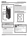
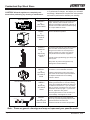
A. Door Handle Assemblies
All Doors
• Install washer on door handle shaft.
• Slide door handle through door.
Right Front & Side Doors:
• Install additional spacing washer(s) as needed.
• Install bushing, door latch and locknut.
Caution! Do not overtighten locknut. Door handle
needs to move smoothly.
Left Front Door:
• Install locking pin and locknut. Securely tighten locknut.
This handle assembly is stationary.
All Doors
• Insert fiber door handle with threads going into door
handle shaft. Turn handle clockwise until tight.
Left Handle
Assembly is
Stationary
Figure 24.3 - Side Door
B. Adjusting The Blower Speed Control
*If Necessary
*The blower speed control for this unit is adjusted at the
factory, and normally does not require further adjustment.
Lock Nut
Locking Pin
Washer
NOTE: When the speed control is turned clockwise, it will
click on to high speed. Turn the speed control clockwise
to decrease the speed. At full clockwise, the blower
should blow gently, but should not stop.
Door
Handle
Shaft
1.
With the stove plugged in, turn the speed control knob
to slow (full clockwise).
Figure 24.1 - Left Front Door
2.
With a small screwdriver, adjust the blower speed by
turning the adjustment mechanism through the hole on
the side of the speed control.
3.
Adjust the speed so the blower runs slowly, but does
not stop. Turn clockwise to slow the blower and
counterclockwise to increase the speed.
Fiber
Handle
Spacing Washers
Door
Latch
Lock
Nut
Bushing
Washer
Handle
Fiber Handle
Figure 24.2 - Right Front Door
Page 24
7006-188G
November 5, 2010
R
Cumberland Gap Wood Stove
8
Operating Instructions
B. Wood Selection and Storage
A. Over-Firing Your Appliance
WARNING
WARNING
FIRE RISK.
Fire Risk
• DO NOT BURN GARBAGE OR FLAMMABLE
FLUIDS SUCH AS GASOLINE, NAPTHA OR
ENGINE OIL.
Do not over-fire.
Over-firing may ignite creosote or will damage
the stove and chimney.
• DO NOT USE CHEMICALS OR FLUIDS TO START A
FIRE.
• Do NOT burn treated wood or wood with salt (driftwood).
• May generate carbon monooxide if burn material other
than wood.
May result in illness or possible death.
To prevent over-firing your stove, DO NOT:
• Use flammable liquids
• Overload with wood
• Burn trash or large amounts of scrap lumber
• Permit too much air to the fire
1. Symptoms of Over-Firing
Symptoms of over-firing may include one or more of the
following:
Hardwood vs Softwood
Your appliance performance depends on the quality of the
firewood you use.
• Chimney connector or appliance glowing
• Roaring, rumbling noises
•
Seasoned wood contains about 8,000 BTUs per pound .
•
Hard woods are more dense than soft woods.
•
Hard woods contain 60% more BTUs than soft woods.
•
Hard woods require more time to season, burn slower and
are harder to ignite.
• Immediately close the door and air controls to reduce
air supply to the fire.
•
Soft woods require less time to dry, burn faster and are
easier to ignite.
• If you suspect a chimney fire, call the fire department
and evacuate your house.
•
Start the fire with softwood to bring the appliance up to
operating temperature and to establish draft.
• Contact your local chimney professional and have
your stove and stove pipe inspected for any damage.
•
Add hardwood for slow, even heat and longer burn time.
• Loud cracking or banging sounds
• Metal warping
• Chimney fire
2. What To Do if Your Stove is Over-Firing
• Do not use your stove until the chimney professional
informs you it is safe to do so.
Hearth & Home Technologies WILL NOT warranty stoves
that exhibit evidence of over-firing. Evidence of over-firing
includes, but is not limited to:
• Warped air tube
• Deteriorated refractory brick retainers
Soft woods
Hard woods
•
•
•
•
•
•
•
•
•
•
•
Douglas Fir
Pine
Spruce
Cedar
Oak
Maple
Apple
Birch
Poplar
Aspen
Alder
• Deteriorated baffle and other interior components
Processed Solid Fuel Fire Logs
•
November 5, 2010
NOT permitted for use in this appliance
7006-188G
Page 25
R
Cumberland Gap Wood Stove
Moisture
C. Burning Process
The majority of the problems appliance owners experience
are caused by trying to burn wet, unseasoned wood.
•
Wet, unseasoned wood requires energy to evaporate the
water instead of heating your home, and
•
Causes evaporating moisture which cools your chimney,
accelerating formation of creosote.
WARNING
Fire Risk.
• Do NOT burn wet or green wood.
• Store wood in dry location.
• Stack wood so both ends are exposed to air.
Wet, unseasoned wood can cause accumulation of
creosote.
In recent years there has been an increasing concern about
air quality. Much of the blame for poor air quality has been
placed on the burning of wood for home heating.
In order to improve the situation, we at Quadra-Fire have
developed cleaner-burning wood appliances that surpass
the requirements for emissions established by our governing
agencies.
These wood appliances must be properly operated in order
to ensure that they perform the way they are designed to
perform.
NOTICE: Improper operation can turn any wood appliance into a smoldering environmental hazard.
1. Kindling or First Stage
Seasoned Wood
•
Cut logs to size
•
Split to 6 inches (152 mm) or less in diameter
•
Air dry to a moisture content of not more than 20%
-
Soft wood - about nine months to dry
-
Hard wood - about eighteen months to dry
It helps to know a little about the actual process of burning in
order to understand what goes on inside the appliance. The
first stage of burning is called the kindling stage.
In this stage:
• Wood is heated to a temperature high enough to evaporate the moisture present in all wood.
• Wood will reach the boiling point of water (212°F) and will
not get any hotter until the water is evaporated.
NOTICE: Seasoning time may vary depending on drying
conditions.
This process takes heat from the coals and tends to cool the
appliance.
Fire requires three things to burn:
Storing Wood
Steps to ensure properly seasoned wood:
•
Stack wood to allow air to circulate freely around and
through woodpile.
•
Elevate wood pile off ground to allow air circulation
underneath.
•
Smaller pieces of wood dry faster. Any piece over 6 in.
(152 mm) in diameter should be split.
•
Wood (whole or split) should be stacked so both ends of
each piece are exposed to air. More drying occurs through
the cut ends than the sides.
•
Store wood under cover to prevent water absorption
from rain or snow. Avoid covering the sides and ends
completely.
WARNING
Fire Risk
Do NOT store wood:
• In front of the appliance.
• In space required for loading or ash
removal.
Page 26
• Fuel
• Air
• Heat
If heat is robbed from the appliance during the drying stage,
the new load of wood has reduced the chances for a good
clean burn.
It is always best to burn dry, seasoned firewood. When the
wood isn’t dry, you must open the air controls and burn at a
high burn setting for a longer time to start it burning.
The heat generated from the fire should be warming your
home and establishing the flue draft, not evaporating the moisture out of wet, unseasoned wood, resulting in wasted heat.
2. Second Stage
In the secondary stage wood gives off flammable gases which
burn above the fuel with bright flames.
During this stage of burning:
• The flames must be maintained and not allowed to go out
to ensure the cleanest possible fire.
• If the flames tend to go out, it is set too low for your burning conditions.
7006-188G
November 5, 2010
R
Cumberland Gap Wood Stove
The Primary Air Slide Control located under the ashlip adjusts the burn rates. Figure 27.1.
3. Final Stage
The final stage of burning is the charcoal stage. This occurs
when the flammable gases have been mostly burned and
only charcoal remains. This is a naturally clean portion of
the burn. The coals burn with hot blue flames.
• It is very important to reload your appliance while enough
lively hot coals remain in order to provide the amount of
heat needed to dry and rekindle the next load of wood.
• It is best to open the Primary Air Control and the Start-Up
Air Controls before reloading. This livens up the coalbed and reduces excessive emissions (opacity/smoke).
E. Air Controls
Start-Up Air System
The combustion air enters at the rear of the firebox through
the rear air tubes. This air supply is controlled by the Startup Air Control. For more air push control IN, for less air pull
control OUT.
Primary Air System
The primary air enters below the ash catcher and is directed
to the upper front of the firebox, near the top of the glass
door and to the lower front of firebox. This preheated air supplies the necessary fresh oxygen to mix with the unburned
gases, helping to create secondary, tertiary and quaternary
combustions. This air is regulated by the Primary Air Slide
Control. For more primary air slide control LEFT, for less air
slide control RIGHT.
• Open door slowly so that ash or smoke does not exit appliance through opening.
• Break up any large chunks and distribute the coals so
that the new wood is laid on hot coals.
Air quality is important to all of us, and if we choose to use
wood to heat our homes we should do so responsibly.
We need to learn to burn in the cleanest way possible allowing us to continue using our wood appliances for many
years to come.
Primary Air
Slide Control
Start-Up Air
Control
Figure 27.1
D. Combustible/Non-Combustible Materials
Primary Slide Control
Start-Up Air Control
•
OPEN - SLIDE LEFT
OPEN - PUSH IN
CLOSE SLIDE RIGHT
CLOSE - PULL OUT
•
•
Combustible Material
Material made of or surfaced with wood, compressed
paper, plant fibers, plastics, or any material capable
of igniting and burning, whether flame-proofed or not,
plastered or unplastered.
Non-Combustible Material
Material which will not ignite and burn. Such materials are
those consisting entirely of steel, iron, brick, tile, slate,
glass or plasters, or any combination thereof.
Materials that are reported as passing ASTM E 136,
Standard Test Method for Behavior of Materials in a
Vertical Tube Furnance at 750 oC and UL763 shall be
considered non-combustible materials.
Non-Combustible Sealant Material
Sealants which will not ignite and burn: Rutland, Inc.
Fireplace Mortar #63, Rutland 76R, Nuflex 304, GE
RTV106 or GE RTB116 (or equivalent).
November 5, 2010
7006-188G
WARNING
Fire Risk.
•
ALWAYS OPERATE THIS APPLIANCE WITH
THE DOOR CLOSED AND LATCHED EXCEPT
DURING START-UP AND RE-FUELING OR
WHEN USING THE FIRESCREEN.
•
OPERATING WITH THE DOOR PARTLY OPEN
CAN CAUSE:
•
HOT EMBERS OR SPARKS TO FALL OUT
• FLAMES AND SMOKE MAY BE DRAWN OUT
FROM FIREBOX OPENING
Page 27
R
Cumberland Gap Wood Stove
H. Building A Fire
F. Heat Output Settings
For maximum operating efficiency with the lowest
emissions, follow these operating procedures:
Before lighting your first fire make certain that the
baffle and blanket are correctly positioned. They
should be resting against the rear support.
1.
Regardless of desired heat output, when loading stove,
burn it with both air controls wide open for 5 to 15 minutes.
2.
Regulate burn rate (heat output) by using the Primary Air
Slide Control (center under ashcatcher). The Start-Up
Air Control (on the right) is used for initial start-up and
reloading.
There are many ways to build a fire. The basic principle
is to light easily-ignitable tinder or paper, which ignites the
fast burning kindling, which in turn ignites the slow-burning
firewood. Here is one method that works well:
3.
Heat output settings are listed below, following 5 to 15
minutes of burning with controls wide open (see #1
above):
1.
Place several wads of crushed paper on the firebox floor.
Heating the flue with slightly crumpled newspaper
before adding kindling keeps smoke to a minimum.
4.
Burn dry, well-seasoned wood.
2.
Lay small dry sticks of kindling on top of the paper.
3.
Open Start-Up Air Control and Primary Air Slide Control
fully. After 5 to 15 minutes, when the fire is well established,
gently pull Start-Up Air Control forward until resistance is
felt. Do not allow control to "spring back" into the open
position.
4.
Make sure that no matches or other combustibles are
in the immediate area of the stove. Be sure the room is
adequately ventilated and the flue unobstructed.
5.
Light the paper in the stove. NEVER light or rekindle stove
with kerosene, gasoline, or charcoal lighter fluid; the results
can be fatal.
6.
Once the kindling is burning quickly, add several full-length
logs 3 inches (76mm) or 4 inches (102mm) in diameter.
Be careful not to smother the fire. Stack the pieces of
wood carefully: near enough to keep each other hot, but
far enough away from each other to allow adequate air
flow between them.
7.
When ready to reload the stove, add more logs. Large
logs burn slowly, holding a fire longer. Small logs burn fast
and hot, giving quick heat.
8.
Adjust the Start-Up Air Control and Primary Air Slide Control; the more you close down (slide right) the Primary Air
Slide Control, the lower and slower the fire will burn. The
more you open (slide left) the Primary Air Slide Control,
the more heat will be produced. The Start-Up Air Control
is only used for the first 5 to 15 minutes.
9.
As long as there are hot coals, repeating steps 7 and 8 will
maintain a continuous fire throughout the season.
G. Burn Rates
1. High Burn Rate - Maximum Heat* - 30,000+ BTU/hr
• Close Start-Up Air Control after 5 to 15 minutes, fully open
(slide all the way to the left) the Primary Air Slide Control.
2. Medium-High Burn Rate* - 15,000 to 30,000 BTU/hr
• Close Start-Up Air Control after 5 to 15 minutes, open the
Primary Air Control 1/4 inch to 1 inch.
3. Medium-Low Burn Rate* - 10,000 to 15,000 BTU/hr
• Close Start-Up Air Control after 5 to 15 minutes, open the
Primary Air Control 1/8 inch to 1/4 inch.
4. Low Burn Rate* - Below 10,000 BTU/hr
• Close Start-Up Air Control after 5 to 15 minutes. Gradually close down (sliding to the right) the Primary Air Slide
Control making sure to maintain flames in the stove. You
must maintain flames during the first few hours of a low
burn to avoid excessive air pollution.
*NOTE: These are approximate settings, and will vary with
type of wood or chimney draft. Due to altitude and other
environmental circumstances, this operational information is
a guideline only.
WARNING
Risk of extreme temperatures!
• Do not operate with Start-Up Air Control in the open position
in excess of 15 minutes!
• Prolonged operation with the Start-Up Air Control in the open
position may cause the combustible materials around the
stove to exceed safe temperature limits.
Page 28
NOTE: The special high temperature paint that your stove is
finished with will cure as your stove heats. You will
notice an odor and perhaps see some vapor rise from
the stove surface; this is normal. We recommend that
you open a window until the odor dissipates and paint
is cured.
NOTE: Stove should be run full open for 15 minutes a day to
keep air passages clean.
7006-188G
November 5, 2010
R
Cumberland Gap Wood Stove
I. Optional Blower Operating Instructions
WARNING
Fire Risk.
• DO NOT BURN GARBAGE OR FLAMMABLE
FLUIDS SUCH AS GASOLINE, NAPTHA OR
ENGINE OIl.
• Do NOT burn treated wood or wood with salt (driftwood).
• May generate carbon monoxide if burn material other
than wood.
May result in illness or possible death.
1. Initial (cold) start-up: Leave blower off until your stove
is hot and a good coalbed is established. The blower
may be turned on approximately 30 minutes after a good
coalbed is established.
2. High burn setting: The blower may be left on throughout the burn at your desired setting.
3. Medium burn settings: The blower should be left off
until a good burn is established, then turned on at your
desired setting.
4. Low burn setting: The blower tends to cool off the
stove. Leave blower off until burn is well established.
Then turn on at your desired rate.
WARNING
5. The highest blower speed is obtained by turning the
speed control on and then adjusting counterclockwise
towards "OFF" as far as possible without turning the
blower off. For a low blower speed, turn the control knob
clockwise as far as possible.
Fire Risk.
Keep combustible materials, gasoline
and other flammable vapors and liquids
clear of appliance.
• Do NOT store flammable materials in the appliance’s
vicinity.
• DO NOT USE GASOLINE, LANTERN FUEL,
KEROSENE, CHARCOAL LIGHTER FLUID OR
SIMILAR LIQUIDS TO START OR “FRESHEN UP” A
FIRE IN THIS HEATER.
J. Opacity (Smoke)
• Keep all such liquids well away from the heater while it
is in use.
Opacity is measured in percent:
Opacity is the measure of how cleanly your appliance is
burning.
• Combustible materials may ignite.
• 100% opacity is when an object is totally obscured by
the smoke column from a chimney, and
• 0% opacity means that no smoke column can be seen.
As you become familiar with your appliance, you should periodically check the opacity. This will allow you to know how to
burn as nearly smoke-free as possible (goal of 0% opacity).
CAUTION
Odors and vapors released during initial operation.
• Curing of high temperature paint.
• Open windows for air circulation.
WARNING !
•
The outside surfaces of this unit will become extremely hot
during use.
•
If this appliance is in a high traffic area or children may be
near it is recommended that you purchase a decorative barrior to go in front of the appliance.
•
Always keep children away while it is operating
•
Do not let anyone operate this appliance unless they are
familiar with these operation instructions.
Odors may be irritating to sensitive individuals.
NOTE:
• Build fire on brick firebox floor.
• Do NOT use grates, andirons or other methods to support
fuel.
It will averserly affect emissions.
November 5, 2010
7006-188G
Page 29
R
Cumberland Gap Wood Stove
K. Clear Space
•
Do NOT place combustible objects within 4 ft (1.2 m) of
the front of fireplace. Figure 30.1.
WARNING
Fire Risk.
•
Do not place combustible objects within 48 inches
in front of the appliance.
•
High temperatures may ignite clothing, furniture or
draperies.
Maintain 4 ft (1.22m) clearance to
combustible in front of appliance
Figure 30.1 - Clear Space
L. Frequently Asked Questions
ISSUES
SOLUTIONS
Odor from appliance
When first operated, this appliance may release an odor for the first several hours. This is
caused by the curing of the paint and the burning off of any oils remaining from manufacturing.
Metallic noise
Noise is caused by metal expanding and contracting as it heats up and cools down, similar to
the sound produced by a furnace or heating duct. This noise does not affect the operation or
longevity of the appliance.
Whirring sound
The blower may produce a whirring sound which increases in volume as the speed is
increased.
Page 30
7006-188G
November 5, 2010
R
Cumberland Gap Wood Stove
M. Correct Baffle & Blanket Placement
INCORRECT POSITIONS
WARNING
Fire Risk
Firebox damage due to improper baffle placement is not covered by warranty. Operate the
wood burning appliance with the baffle in the
correct position only.
Not doing so could result in:
• Reduced efficiency
• Overheating the chimney
• Overheating the rear of the firebox
Ceramic Blanket and Baffle Board are NOT in
• Poor performance
Ensure correct baffle placement and replace baffle components if damaged or missing.
contact with the back of the firebox.
These are generic drawings and may not represent
your specific model.
CORRECT POSITION
Ceramic Blanket is NOT in contact with the
back of the firebox and NOT even with the Baffle Board in the front.
Back of Firebox
Ceramic Blanket
Back of Firebox
Ceramic Blanket
Baffle Board
Baffle Board
Ceramic Blanket and Baffle Board MUST be
in contact with the back of the firebox and
even with each other in the front.
Figure 31.1
November 5, 2010
Ceramic Blanket is bunched up at the back of
the firebox and NOT even with the Baffle Board
in the front.
Figure 31.2
7006-188G
Page 31
R
Cumberland Gap Wood Stove
9
Maintaining & Servicing Your Appliance
2. Ash Removal System (ARS) Operating and Cleaning
A. General Maintenance
•
Frequency: Weekly when in constant operation or as
needed.
By: Homeowner
1. Creosote (Chimney) Cleaning
•
•
•
Frequency: Every 2 months during heating season or as
recommended by a certified chimney sweep; more frequently
if chimney exceeds or is under 12-14 ft. (measured from base
of appliance).
Injury Risk.
By: Certified Chimney Sweep
• Gloves recommended
1. Remove all ash from the firebox and extinguish all hot embers
before disposal. Allow the appliance to cool completely. It is
also recommended that before each heating season the entire
system be professionally inspected, cleaned and repaired if
necessary.
CAUTION
• Ash coals can remain extremely hot for
several days.
1.
The stove and ashes must be completely cooled down before
using the Ash Removal System. The hinged door will open
from the right hand side. Pull ash pan out carefully.
2.
Clean ash down through the ash removal system grate into
the drawer below. If there are large pieces in the ashes, you
can remove the grate before brushing the ash into the drawer.
3.
Be sure to replace the grate before operating the stove.
Remember to leave 1/4 to 1/2 inch (6-13mm) of ash on the
firebox floor to act as a natural grate, allowing air to flow freely
underneath wood
4.
Replace ash pan and close ash door handle. Dispose of the
ashes following the directions on page 33.
2. Close the door tightly and proceed with sweeping the chimney.
3. Sweep the collected ashes into the ash removal box, and empty.
Clean out the remaining ashes from firebox.
4. Open top-loading door and vacuum out.
Inspection: Inspect the system at the appliance connection and at
the chimney top. Cooler surfaces tend to build creosote deposits
quicker, so it is important to check the chimney from the top as well
as from the bottom.
Formation and Need For Removal: When wood is burned slowly, it
produces tar and other organic vapors which combine with expelled
moisture to form creosote.
The creosote vapors condense in the relatively cool chimney flue
of a newly-started or a slow-burning fire. As a result, creosote
residue accumulates on the flue lining. When ignited, this creosote
creates an extremely hot fire which may damage the chimney or
even destroy the house.
The chimney connector and chimney should be inspected once
every 2 months during the heating season to determine if a creosote
or soot buildup has occurred. If creosote or soot has accumulated,
it should be removed to reduce the risk of a chimney fire.
Ash Door
Handle
Figure 32.1
Do not allow ashes to build up in the ashpan until they reach
the grate. This will lead to premature deterioration of the
grate and make it difficult to empty the ash pan.
WARNING
Fire Risk.
Prevent creosote buildup.
• Inspect chimney connector and chimney once
every two months during heating season.
• Remove creosote to reduce risk of chimney fire.
• Ignited creosote is extremely HOT.
WARNING
Fire risk
Injury risk
Make sure ash removal system door
Air leakage may cause:
• Over-fire condition.
• Flame and/or smoke spillage.
• Wood to burn too fast.
WARNING
Fire Risk.
• Do not use chimney cleaners or flame
colorants in your appliance.
Will corrode pipe.
Page 32
Swings Open
Do not operate with ash pan door open or with
ash pan removed
7006-188G
November 5, 2010
R
Cumberland Gap Wood Stove
3. Disposal of Ashes
5. Glass Cleaning
•
•
•
•
Frequency: When ash is within 1-3/4 in. (44mm) of firebox
lip
By: Homeowner
Frequency: As desired
By: Homeowner
Clean glass with a non-abrasive glass cleaner. Abrasive
cleaners may scratch and cause glass to crack. If the
deposits on the glass are not very heavy, normal glass
cleaners work well. Heavier deposits may be removed
by using a damp cloth dipped in wood ashes or by using
a commercially available oven cleaner.
Ashes should be placed in a metal container with a
tight fitting lid. The closed container of ashes should
be placed on a non-combustible floor or on the ground,
well away from all combustible materials, pending final
disposal.
After using an oven cleaner, it is advisable to remove any
residue with a glass cleaner or soap and water. Oven
cleaner left on during the next firing can permanently
stain the glass and damage the finish on plated metal
surfaces.
If the ashes are disposed of by burial in soil or otherwise
locally dispersed, they should be retained in the closed
container until all cinders have thoroughly cooled.
A portion of the combustion air entering the firebox is deflected
down over the inside of the door glass. This air flow “washes”
the glass, helping to keep smoke from adhering to its surface.
WARNING
Fire Risk.
Disposal of Ashes
• Ashes should be placed in metal container with tight
fitting lid.
• Do not place metal container on combustible surface.
• Ashes should be retained in closed container until all
cinders have thoroughly cooled.
When operated at a low burn rate, less air will be flowing over
the glass and the smokey, relatively cool condition of a low
fire will cause the glass to become coated.
Operating the appliance with the Primary Air Control all
the way open for 15-20 minutes should remove the built up
coating.
4. Cleaning Plated Surfaces
•
•
CAUTION
Frequency: Prior to first burn and then as desired
By: Homeowner
Handle glass assembly with care.
Clean all the fingerprints and oils from plated surfaces
BEFORE firing the appliance for the first time. If not
cleaned properly before lighting your first fire, the oils
can cause permanent markings on the plating.
After the plating is cured, the oils will not affect the
finish and little maintenance is required. Wipe clean
as needed.
Glass
Assembly
•
•
•
•
When cleaning glass:
• Avoid striking, scratching or
slamming glass.
• Do NOT clean glass when hot.
Do NOT use abrasive cleaners.
Use a hard water deposit glass cleaner on white film.
Use commerical oven cleaner on heavier deposits.
Remove all residue of oven cleaner or will permanently
stain glass on next firing.
•
Refer to maintenance instructions.
CAUTION
• Do not use polishes with abrasives.
It will scratch plated surfaces.
November 5, 2010
7006-188G
Page 33
R
Cumberland Gap Wood Stove
B. Appliance Inspection - Routine
D. Glass Replacement
•
Frequency: Every 2 months at the same time the chimney and chimney connector are inspected.
1.
•
By: Homeowner
2.
Check for:
3.
• Cracks in glass
4.
• Door handle - smooth cam operation
• Baffles are in correct placement
5.
• Baffle for warpage
• Firebrick for cracks, broken or crumbly
• Door gasket. (Dollar bill test). Place a dollar bill between
the stove and the door and then shut the door. If you can
pull the dollar bill out, replace the door gasket.
6.
• Glass frame for loose screws
7.
8.
C. Inspect Firebrick & Replacement
Instructions
•
Frequency: After each ash removal
•
By: Homeowner
9.
Replace the firebrick if they become crumbly and/or if there
is a 1/4 inch (6.35mm) gap between the bricks.
The firebox is lined with firebrick, which has exceptional insulating properties. Do not use a grate; simply build a fire on
the firebox floor. Do not operate appliance without firebrick.
Ensure that the firebricks are correctly positioned and that
the firebox does not contain any broken brick prior to operating the unit.
Ensure that the fire is out and the appliance is cool
to the touch.
Protect a table or counter top with padding or towels.
Protect your hands and wear gloves to prevent injury.
Remove the door with the broken glass by lifting the
door up and off of the hinges.
Lay door face down on a table or counter making sure
the door handle and fiber handle hangs over the edge
so the door lays flat on a soft surface.
Remove the screws from each glass retainer and
remove the glass. (If screws are difficult to remove,
soak with penetrating oil first).
Center the glass with edges evenly overlapping the
opening in the door, (i.e. same space top and bottom,
left and right sides).
Replace the glass retainers. Be careful not to cross
thread the screws.
Tighten each retainer just a few turns until each is
secured. Check again for centering of glass in door
frame. Continue to tighten each retainer alternately,
a few turns at a time, until the glass is snug. DO NOT
OVERTIGHTEN.
Replace the door on the appliance.
Quadra-Fire stoves are equipped with ceramic super
heat-resistant glass, which can only be broken by impact
or misuse.
Do not slam stove door or impact the glass. When closing
door, make sure that logs do not protrude against the
glass. Inspect glass regularly.
If you find a crack or break, immediately put the fire out
and return the door to your dealer for replacement of glass
before further use.
1. After the coals have completely cooled, remove all old
brick and ash from unit and vacuum out firebox.
WARNING
2. Remove new brick set from box and lay out to the
diagram shown in the instructions that come with the
replacement brick set
Handle glass with care.
Glass
Assembly
3. Lay bottom bricks in unit.
4. Install rear bricks on the top of the bottom bricks. Slide
top of bricks under clip on back of firebox wall and push
bottom of bricks back.
• Inspect the gasket to ensure it is
undamaged.
• Do NOT strike, slam or scratch glass.
• Do NOT operate appliance with glass
& door assembly removed.
• Do NOT operate with glass cracked, broken or scratched.
5. Install side bricks. Slide top of brick under clips on side
of firebox and push the bottom of the brick until it is flush
with the side of the unit.
Use Part #832-0550 when ordering individual
brick. Provide brick dimension or copy the page
in the Service Parts List showing the brick diagram, mark the desired brick and take it to your
authorized dealer.
Page 34
7006-188G
WARNING
Fire Risk.
Injury Risk.
• Use only glass specified in manual.
• DO NOT REPLACE with any other material.
Glass breakage will occur.
November 5, 2010
R
Cumberland Gap Wood Stove
E. Baffle Removal & Installation
1. Remove all ash from firebox, and extinguish all hot embers
before disposal into a metal container.
2. Remove ceramic blanket & baffle together
3. With a 3/16” Allen wrench, remove the front manifold tube
retainer bolts on the air channel under the end of the front
tube. Figure 35.1.
NOTE: Soak the bolts with penetrating oil for at least 15
minutes before trying to remove them.
4. To remove manifold tube, slide the tube to one side until one
end is out of its hole. Then, while lifting that end of the fiber
board baffle, pull tube up over the air channel and out of hole
at the other end.
5. Slide fiber board baffle forward to front of stove and straight
out through door. Figure 35.2.
6. To install the fiber board baffle, repeat steps 2 through 4 in
reverse.
7. The front manifold tube is shorter than the back two. It is
IMPORTANT that they are replaced in the correct position or
your stove will not operate properly.
8. Be sure the fiber board baffle and ceramic blanket are fully
pushed back into position and the blanket is down flat. The
front of the blanket should be flush with the front of the baffle.
Baffle Board
Push baffle board up slightly to
allow room to turn the handle
Figure 35.1
Ceramic Blanket
Baffle Board
Figure 35.2
November 5, 2010
7006-188G
Page 35
R
Cumberland Gap Wood Stove
F. Quick Reference Maintenance Guide
CAUTION! Allow the appliance to completely cool
down before performing any cleaning or maintenance.
Baffle & Blanket
Blanket
Baffle
Optional Blower
Chimney System
Start the first inspection after the first 2 months of use,
or if performance changes, and adjust your schedule
accordingly. Maintenance is required for safe operation
and must be performed to maintain your warranty.
Frequency
MONTHLY
or
After Every
Cord of Wood
YEARLY
or
After Every
4 Cords of
Wood
EVERY 2
MONTHS
or
After Every
4 Cords of
Wood
Task
Baffle and blanket placement is critical to heat
output, efficiency and overall life of the unit.
Make sure the baffle is pushed all of the way to
the back of the firebox and the blanket is laying
flat. Inspect baffle for cracks.
Vacuum the blower impellers.
The chimney and chimney cap must be inspected for soot and creosote every two months
during the burn season or more frequency if
chimney exceeds or is under 14-16 ft (4.3m4.8m) measured from bottom of appliance.
This will prevent pipe blockage, poor draft, and
chimney fires.
Always burn dry wood to help prevent cap
blockage and creosote build-up.
Firebrick & Ash Removal
WEEKLY
or
After Every
25 Loads of
Wood
Door & Glass Assemblies
WEEKLY
or
After Every
25 Loads of
Wood
Ashes must be cool before you can dispose of
the ashes in a non-combustible container.
Firebrick is designed to protect your firebox.
After ashes are removed, inspect the firebrick
and replace firebricks that are crumbling,
cracked or broken.
Keep door and glass gasket in good shape to
maintain good burn times on a low burn setting.
To test: place a dollar bill between the stove and
door and then shut the door. If you can pull the
dollar out, remove one washer from door handle
behind latch cam and try again. If you can still
pull it out, replace the door gasket.
Check the glass frame for loose screws to prevent air leakage. Check glass for cracks.
Door Handle
Latch Cam
Spacing Washers
WEEKLY
or
After Every 25
Loads of Wood
Check the door latch for proper adjustment.
This is very important especially after the door
rope has formed to the stove face.
Check door handle for smooth cam operation.
Note: These are generic drawings and may not represent your specific model.
Page 36
7006-188G
November 5, 2010
R
Cumberland Gap Wood Stove
10
Troubleshooting Guide
With proper installation, operation, and maintenance your woodstove will provide years of trouble-free service. If you do
experience a problem, this troubleshooting guide will assist you or a qualified service person in the diagnosis of a problem
and the corrective action to be taken.
Start Fire Problems
Possible Cause
Solution
Can not get fire started
Excessive smoke or spillage
Burns too slowly
Not enough heat output
Not enough kindling/paper or no
kindling/paper
Use dry kindling, more paper. Arrange kindling &
wood for air movement.
Check for restricted termination cap
Check for blockage of outside air kit (if installed).
Check for flue blockage.
Not enough air for fire to ignite
Pre-warm flue before starting fire (refer to Building
a Fire Section).
Check for adequate vent height (refer to Chimney
Height Section).
Open window below the appliance towards the
wind.
Wood condition is too wet, too
large
Use dry, seasoned wood (refer to Seasoned Wood
Section).
Bed of coals not established
before adding wood
Start with paper & kindling to establish bed of
coals (refer to Building a Fire Section).
Flue blockage such as birds’
nests or leaves in termination
cap
Have chimney inspected for creosote and cleaned
by a certified chimney sweep.
Down draft or negative pressure
Competition with exhaust
devices
Do not use exhaust fans during start-up (refer to
Negative Pressure Section).
Fire burns too fast
Open window below the appliance towards the
wind.
Mix in hardwood.
Extremely dry or soft wood
Mix in less seasoned wood after fire is established
(refer to Wood Fuel Section).
Check for correct vent height; too much vertical
height creates overdrafting.
Overdrafting
November 5, 2010
Check location of vent termination (refer to
Chimney Termination Requirement Section).
7006-188G
Page 37
R
&XPEHUODQG*DS
6HUYLFH3DUWV
1RQ&DWDO\WLF)URQW6LGH/RDG:RRG6WRYH
%HJLQQLQJ0DQXIDFWXULQJ'DWH-DQ
(QGLQJ0DQXIDFWXULQJ'DWH$FWLYH
&80%*$30%.WR$FWLYH&80%*$330+WR$FWLYH
&80%*$33&5WR&80%*$33*5WR&80%*$330%WR
Exploded Drawing
%ULFN6HW
$VVHPEO\
10-19-10
3DUWQXPEHUOLVWRQIROORZLQJSDJH
Page 38
7006-188G
November 5, 2010
R
&XPEHUODQG*DS
6HUYLFH3DUWV
%HJLQQLQJ0DQXIDFWXULQJ'DWH-DQ
(QGLQJ0DQXIDFWXULQJ'DWH$FWLYH
,03257$177+,6,6'$7(',1)250$7,21:KHQUHTXHVWLQJVHUYLFHRUUHSODFHPHQW
SDUWVIRU\RXUDSSOLDQFHSOHDVHSURYLGHPRGHOQXPEHUDQGVHULDOQXPEHU$OOSDUWVOLVWHG
LQWKLVPDQXDOPD\EHRUGHUHGIURPDQDXWKRUL]HGGHDOHU
,7(0
'(6&5,37,21
&200(176
6WRFNHG
DW'HSRW
3$57180%(5
6KLHOG)OXH
)OXH6KLHOG7RS
7RS0XVW6SHFLI\FRORU
)OXH7UDQVLWLRQ$VVHPEO\
0DWWH%ODFN
3RUFHODLQ0DKRJDQ\
)W/HQJWK
%DFN6KLHOG
3RUFHODLQ0DKRJDQ\
*DVNHW´)LHOG&XWWR6L]H)DFH'RRU
6LGH/HIW0XVW6SHFLI\FRORU
'RRU/HIW
<
0DWWH%ODFN
)DFH0XVW6SHFLI\FRORU
325
*DVNHW5RSH´)LHOG&XWWR6L]H
0%.
325
)W/HQJWK
0DWWH%ODFN
0%.
3RUFHODLQ0DKRJDQ\
0DWWH%ODFN
3RUFHODLQ0DKRJDQ\
*DVNHW´)LHOG&XWWR6L]H)DFH'RRU
0%.
)W/HQJWK
<
325
0%.
325
<
&HUDPLF)LEHU%ODQNHW´7KLFN
<
%DIIH%RDUG
659
<
$VK*UDWH
0DQLIROG7XEH6HW
0DQLIROG&OLS6FUHZV
$VKOLS)URQW0XVW6SHFLI\FRORU
'RRU5LJKW0XVW6SHFLI\FRORU
$UV'RRU$VVHPEO\
78%(6
<
3NJRI
<
0DWWH%ODFN
0%.
3RUFHODLQ0DKRJDQ\
0DWWH%ODFN
3RUFHODLQ0DKRJDQ\
325
0%.
325
*DVNHW5RSH)LHOG&XWWR6L]H
)W/HQJWK
+DQGOH$VK5HPRYDO6\VWHP
659
1XW/RFNLQJ'RRU+DQGOH
3NJRI
<
6FUHZ3DQ+HDG3KLOLSV;
3NJRI
$
<
$UV3DQ
6LGH5LJKW0XVW6SHFLI\FRORU
$VKOLS6LGH0XVW6SHFLI\FRORU
0DWWH%ODFN
3RUFHODLQ0DKRJDQ\
0DWWH%ODFN
3RUFHODLQ0DKRJDQ\
0%.
325
0%.
325
$GGLWLRQDOVHUYLFHSDUWQXPEHUVDSSHDURQIROORZLQJSDJH
November 5, 2010
7006-188G
Page 39
R
&XPEHUODQG*DS
6HUYLFH3DUWV
%HJLQQLQJ0DQXIDFWXULQJ'DWH-DQ
(QGLQJ0DQXIDFWXULQJ'DWH$FWLYH
,03257$177+,6,6'$7(',1)250$7,21:KHQUHTXHVWLQJVHUYLFHRUUHSODFHPHQW
SDUWVIRU\RXUDSSOLDQFHSOHDVHSURYLGHPRGHOQXPEHUDQGVHULDOQXPEHU$OOSDUWVOLVWHG
LQWKLVPDQXDOPD\EHRUGHUHGIURPDQDXWKRUL]HGGHDOHU
,7(0
'(6&5,37,21
&200(176
3$57180%(5
0DWWH%ODFN
6LGH'RRU$VVHPEO\0XVWVSHFLI\FRORU
6WRFNHG
DW'HSRW
0%.
3RUFHODLQ0DKRJDQ\
30+
%UDFNHW'RRU/RFN
659
<
*DVNHW'RRU´)LHOG&XWWR6L]H
)LEHU+DQGOH
)W
<
6FUHZ)ODW+HDG3KLOLSV[
3NJRI
6FUHZ3DQ+HDG3KLOLSV[
3NJRI
0DWWH%ODFN
0%.
3RUFHODLQ0DKRJDQ\
325
6LGH'RRU0XVWVSHFLI\FRORU
6LGH'RRU+DQGOH*ROG
6LGH'RRU6KLHOG
659
'RRU+DQGOH/HIW
'RRU+DQGOH5LJKW
*ROG
1LFNHO
*ROG
1LFNHO
6LGH'RRU/DWFK%UDFNHW
%ULFN6HW
<
%ULFN$VVHPEO\&RPSOHWH6HW
3NJRI
%ULFN´[´[´
4W\5HT
%ULFN´[´[´Z+ROHVHHGLDJUDP
4W\5HT
%ULFN´[´[´
4W\5HT
%ULFN´[´[´
4W\5HT
%ULFN´[´
4W\5HT
%ULFN´[´DQJOHGVHHGLDJUDP
4W\5HT
%ULFN´[´[´
4W\5HT
%ULFN8QFXW0XVWVSHFLOI\VL]HZKHQRUGHULQJ
%5,&.
659
3NJRI
3NJRI
<
$GGLWLRQDOVHUYLFHSDUWQXPEHUVDSSHDURQIROORZLQJSDJH
Page 40
7006-188G
November 5, 2010
R
&XPEHUODQG*DS
6HUYLFH3DUWV
%HJLQQLQJ0DQXIDFWXULQJ'DWH-DQ
(QGLQJ0DQXIDFWXULQJ'DWH$FWLYH
,03257$177+,6,6'$7(',1)250$7,21:KHQUHTXHVWLQJVHUYLFHRUUHSODFHPHQW
SDUWVIRU\RXUDSSOLDQFHSOHDVHSURYLGHPRGHOQXPEHUDQGVHULDOQXPEHU$OOSDUWVOLVWHG
LQWKLVPDQXDOPD\EHRUGHUHGIURPDQDXWKRUL]HGGHDOHU
,7(0
'(6&5,37,21
&200(176
6WRFNHG
DW'HSRW
3$57180%(5
0DWWH%ODFN
&RPSRQHQW3DFN,QFOXGHV%DIIH'LYHUWHUDQG,QVWUXFWLRQV
/HJ/HYHOLQJ1XWV%ROWV7RXFK8S3DLQW2ZQHUV0DQXDO
3RUFHODLQ0DKRJDQ\
:DUUDQW\&DUG
'LYHUWHU%DIIH5HTXLUHGRQDOO+RUL]RQWDO,QVWDOODWLRQV
/HYHOLQJ$VVHPEO\
0DWWH%ODFN
3DLQW7RXFK8S
<
<
)W/HQJWK
<
*ODVV7DEV
3NJRI
.QRE
3NJRI
3RUFHODLQ0DKRJDQ\
*ODVV$VVHPEO\
*DVNHW5RSH´)LHOG&XWWR6L]H
/DWFK$UV
/DWFK%ORFN'RRU
/DWFK0DJQHW
6LGH'RRU+LQJH$VVHPEO\
6SHHG&RQWURO2QO\5KHRVWDW
<
<
$&&(6625,(6
%ORZHU$VVHPEO\
)LUHVFUHHQ
6&5
6FUHHQ+DQGOH
+76+/'
+RUL]RQWDO+HDW6KLHOG5HTXLUHGRQDOO+RUL]RQWDO,QVWDOODWLRQV
2XWVLGH$LU.LW
<
)URQW&RYHU
2XWVLGH$LU&ROODU$VVHPEO\
2XWVLGH$LU6KLHOG
5HDU&KDQQHO
5HDU&RYHU3ODWH
6LGH&KDQQHOV
<
)$67(1(56
$YN5LYQXW5HSDLU.LW5LYQXW7RROV
5,91875(3$,5
<
%ROW+H[+HDG;
3NJRI
$
<
1XW/RFNLQJ'RRU+DQGOH
3NJRI
<
1XW6HU)ODQJH6PDOO
3NJRI
<
6FUHZ)ODW+HDG3KLOLSV;
3NJRI
<
6FUHZ3DQ+HDG3KLOLSV;
3NJRI
$
<
6FUHZ3DQ+HDG3KLOLSV;
3NJRI
<
6FUHZ3DQ+HDG3KLOLSV;
3NJRI
<
6FUHZ6KHHW0HWDO;6*ULS
3NJRI
<
November 5, 2010
7006-188G
Page 41
R
Cumberland Gap Wood Stove
C. Warranty Policy
Page 42
7006-188G
November 5, 2010
R
Cumberland Gap Wood Stove
November 5, 2010
7006-188G
Page 43
R
CONTACT INFORMATION:
Hearth & Home Technologies
1445 North Highway
Colville, WA 99114
Division of HNI INDUSTRIES
Please contact your Quadra-Fire dealer with any questions or concerns.
For the number of your nearest Quadra-Fire dealer,
log onto www.quadrafire.com
CAUTION
and maintenance
instructions included.
• Read, understand and
follow these instructions
for safe installation and
operation.
• Leave this manual with
party responsible for
use and operation.
T
O
N RD
O A
D SC
I
• Important operating
D
DO NOT DISCARD THIS MANUAL
We recommend that you record the following pertinent
information for your CUMBERLAND GAP WOOD STOVE
Date purchased/installed:
Serial Number:
Location on appliance:
Dealership purchased from:
Dealer phone:
Notes:
This product may be covered by one or more of the following patents: (United States) 5341794, 5263471, 6688302, 7216645,
7047962 or other U.S. and foreign patents pending.
Page 44
7006-188G
November 5, 2010