1
> >» PyLE
м PRO
T_T
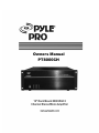
Owners Manual
PT8000CH
19" Rack Mount 8000 Watt 8
Channel Stereo/Mono Amplifier
www.pyleaudio.com
Thank you for purchasing the PYLE PRO PT8000CH power amplifier.
The PT8000CH contains the excellent performance and reliability that
PYLE PRO products have been recognized for. The PT8000CH fea-
tures the flexibility needed for demanding custom installation appli-
cations. It is ideal for use in home theater, stereo, multi-room, multi-
zone and commercial applications. For best performance, please
carefully read the instructions in this manual.
Table Of Contents Page
Features ---------=============oeecooeea ooo eee
Ргоп! Рапе! О1а0гаМ ===================================================----------3
Rear Panel Diagram ======================================================-=------4
System Design &Operation Considerations -------==-==========accncaca===-5-6
System Design Examples ----------=-============ce=eeeeeeceeeeeeece eee nee /
Diagram 4 - Multi Room Installation =========================================-- 8
Diagram 5 - Multi-Zone Installation 41 ===================================----- 9
Diagram 6 - Multi-Zone Installation 4F2 -------=-=-=======e=====nanancacaaaaas 10
Diagram 7 - Home Theater/Multi-Room Installation -----------------------11
Installation Considerations =============================================------- 12
Installation ------------======e=ecaaaanaaaaaaaaanaaaana aaa aaa IN
Operation ------------=--=--======-eeeeeeeeeneeeeeo eee eee $
Troubleshooting ==============ттеттттетететчетеенттеетеетнееееееенееееееее--- 18-19
Specifications -----------===-====-=-===———————————————————[————————————————_Z
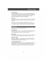
FEATURES
Audiophile Design
Sophisticated design and superior internal components result in outstanding
sound quality, performance and long term reliability.
Advanced Protection
Each channel is individually protected. If the circuitry determines that a chan-
nel must be shut down for protection, a rare occurrence, only the channel
affected will be turned off. The other channels will continue to play. Once
conditions return to normal, the affected channel will be turned back on and
operate as normal.
Flexible Input Selection
Each of the 8 channels can be assigned a variety of source inputs. A dedi-
cated input can be assigned to each channel. Each channel can also be con-
figured to play common signals from the Bus or Auxiliary inputs. This provides
the flexibility needed in sophisticated custom audio installations.
Bridging
The power output of adjacent channels can be combined to provide extra
power when needed in certain areas. This is easily accomplished by flipping a
single switch.
Individual Channel Level Adjustments
Each channel has its own level adjustment. This allows the loudness of each
speaker to be perfectly matched to its area.
Multiple Power Modes and Output Trigger
There are three ways to turn the amplifier on: constant, trigger and audio
sense. This allows the amplifier to operate seamlessly as part of a sophisticat-
ed custom installation. Aseparate output trigger allows the amplifier to acti-
vate other components via a voltage trigger.
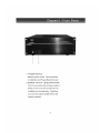
Diagram 1 - Front Panel
Ci
PRO
LAR ELE
FTEODEDCH
1. POWER SWITCH
Master power switch. Turns off power
to amplifier and Power Mode Circuitry.
2. POWER QUTPUT LEVEL INDICATOR
This is level meter which shows outputs
levels of ch 1-2 ch 3-4 ch 5-6 & ch 7-8
condition on the operation. Therefore,
you can see output condition thru this
master indicator.
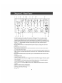
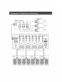
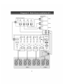
Diagram 2 - Rear Panel
1 2 3 4 5 6 7 a g 10 11
| ==> - | mr | — = [Tee
2 1 # El | @ + - @ «т “-
eA IE 210 ETS PES
wn = SE SE 7 yr Чар a a
hacia) à SCI В В Е ВЫ.
ee en om mA O AO ELO EE BEA
= = a == A
Ea == ==. a= <=. "E E E» 5
o «()) a (DO) O0 у”
: QO O00 | 00 OO [=
AL —
12 13 14 15 16 17 18
1-2. Main bus inputs allow outputs from receivers, CD players, TVs, or any stereo audio
sources to be amplified across all channels for easy multi-room applications. Auxiliary
inputs allow an additional audio source to be played on any channel that is switched to AUX.
3-4.Bus outputs allow the bus inputs to be sent to other amplifiers or a daisy chain without the
need for *Y'" cables splitters. Auxiliary out-puts allow you to daisy chain the input to
other audio sources,
=. Bridging switch allows you to easily double the power output by coupling two chan-nels
together.
6.Level controls for each channel.
7.Input Selection switch allows you to select between the common bus and auxiliary inputs,
er the individual channel input.
8.0ne switch allows you to select which stereo input channel will play through the speaker out-
puts: left, right, or left and right combined. If switched to Left + Right,both input channels are
combined.
9.Gold plated individual channel inputs allow you to connect different audio sources to each
channel.
10, Line signal output
11 Voltage Selector 110-220V
12.The Power Mode switch is used to toggle between three different trigger methods to power
up the amplifier.
13.12V output to turn on other devices when amplifier is powered up. Connect to projector
screens, powered drapes, or other devices with voltage triggers.
14.12-13V A/C or D/C input to trigger power up with voltage from another device, such as a
receiver.
15.5peaker channel output binding posts.
16.5peaker channel bridged mode binding.
17.3-Prong removable power plug.
18.Fused AC
SYSTEM DESIGN & OPERATION CONSIDERATIONS
To best understand system design and operation ofthe PTBOOOCH it is useful to
understand the following terms and features as they relate to the PTÉOOOCH.
Multi-Room
A system design that plays the same source atthe same time in all rooms. [fa
change is made in one room, the same change takes place in all other
rooms. For example, if a listener changes from CD to Tuner in the bedroom,
the same change will be heard in the kitchen. Note: With the use of volume
controls or speaker switchers the volume of each room can be controlled sep-
arately ofthe other rooms.
Multi-Zone
À system design that allows different sources to be played in each room. À
change in one room can be made without changing the other rooms. Far
example the CD player can be heard in the bedroom while the kitchen is
playing the tuner,
Bridging
The combining of 2 channels to create one mono channel, Itis useful when
more volume is needed in a particular area.
Source
Component, audio or video, that provides an audio signal. Examples are CD,
VCR, DVD, tape deck and tuner. The source provides the audio information
that is amplified by the BBB35.
Channel
A distinct unit of the amplifier that provides output to one speaker. On the
FTS000CH the input to each channel can be configured to select from the BUS
INPUT, the AUX INPUT or that channel's unique CHANNEL INPUT. Two adja
cent channels can be bridged to provide higher power to one speaker.
Level Controls
Allows any of the channels to be adjusted independently to raise or lower the
output of each channel. This may be used to control the speaker output in
order to balance different rooms or areas of the system.
BUS*AUX*LINE Switch
Allows each channel to play a variety of different inputs, Depending on the
switch position the channel amplifies the signal connected to the BUS input,
the AUX input, orits own LINE input,
R R+L L Switch
When either à BUS or AUX input is selected, this switch is used to direct the
channel to play the left signal from the input “L” orthe right signal from t
input “R” ,oracombinedright and left signal from the input “R+L"
SYSTEM DESIGN & OPERATION CONSIDERATIONS
Bus Input
Allows the signal from a source to be distributed to any of the 17 channels
on the amplifier.
Auxiliary Inputs
Allows a the signal from a secondary source to be distributed to any of the 12
channels of the amplifier.
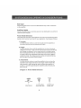
Power Mode Selection
There are three ways to turn the amplifier on and off. Use the following list to
decide which mode will work best for your application. See Diagram 3 below,
1. Constant
Use this selection when you wish to manually turn the amplifier on
and off by using the front mounted power button.
2. Trigger
Use this selection If you wish the amplifier tum on when it receives
voltage (12-15V A/C or D/C} from an external source and turn off once
that voltage has stopped. Some components have voltage outputs
that are designed for this use. In addition there are devices that can
be used as part of an automated system that will provide voltage to
enable the mode. The voltage source must be connected to the trig-
ger-input jack on the back of the amplifier.
3. Audio Sense
Use this selection when you want the amplifier to turn on when the
amplifiers main input receives an audio signal. At the moment tha
gither the leftor right input jacks receive a signal the amplifier is
turned on. Once the signal stops the amplifier wats 3 minutes and
then turns off.
Diagram 3: Power Mode Selection
{CONTROL
11-197 ADS MEA RS
FRE TECH AT UT
O О
; 2 \mmx5.5mm J.omm Power
Mode Switch Power Input Jack Output Jack
SYSTEM DESIGN EXAMPLES
There are many ways to configure the PTBOO0CH amplifier. The following pages
contain some typical installation examples. Use these examples to generate
ideas for your system design.
Multi-Room Installation Example (Diagram 4)
This illustrates the simplest use of the BBB35, distributing audio throughout
the home. In this example only one source can be selected at a time, all pairs
of speakers have the same audio signal available.
The Input Selection switch issatto “BUS” on all channels, Adjacent channe
are assigned left and right.
Multi-Zone Example #1 (Diagram 3)
This illustrates the simplest way to provide an audio signal to one area that is
independent of the main audio signal. Zone 2 uses a CD player connected to
justthat Zone. The rest of the system operates Zone 1 and is connected to
the preamplifier / receiver.
The Input Selection switch on channels 1-10issetto “BUS” with adjace
channels assigned left and right. The Input Selection Switch on channels 11
and 12 are setto “LINE”
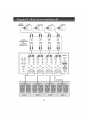
Multi-Zone Example #2 (Diagram 6)
This illustrates the ability to listen to different audio signals in each zone, inde-
pendent of avery other zone. The system relies on a multi-zone preamplifier
or up to 6 independent preamplifiers.
The Input Selection switch on each channel is setto “LINE”
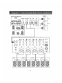
Home Theater / Multi-Room Example (Diagram 7)
This configuration allows the user to access the sources connected to a home
theater receiver for use in a multi-room installation. Itrelies on the home the-
ater receiver having a multi-room or similar output.
The Input Selection switch on each channel is setto “BUS” with adjace
channels assigned left and right.
—
=
‚9
®
Г.
о
Е
=
O
=
X
=
=
=
|
hs
=
©
ds
©
©
m
AUDIO SOURCES
PREAMPLIFIER / RECEIVER
mC
Room 4
О ©
| ho Oil
cou | 7
haa 90
100: a: 798
cou 1 0
Ia: IF SO
ego E: ¡Y
edad: 1
Ia; 1790
Eo El 728
Sl
* ec» ai Wi
138
i $
"1%
Room 2
C
fa loto
00 00 0
100 091
> ajo:
Room 1
©
Le speaker Right speaker Lal epeañor Fi speaker De Ph po Led Epeañar Righl spaaiisr
=i
Diagram 5 - Multi Zone Installation #1
AUDIO SOURCES
PREAMPLIFIER | RECEIVER
x OVD
OUTPUT INPUT INPUT
L L OR LR
úl Tl
A
o o о о о о o o
Left speaker Fightapeaker —— Leflapesiar Right speaker Lefapesñor Rightspeakes | | Lafspesker Right speaker
ZONE 1 ZONE 2
Diagram 6 - Multi Zone Installation #2
AUDIO CD Player DVD Player
4 STEREO NET PUT
PREAMPLIFIERS
OR fot] CUTPUT
MULTIZONE L E L
PREAMPLIFIER =;
ZONE 1
10
Diagram 7 - Home [heater/Multi Room Installation
HOME THEATER RECEIVER
SPEAKER
OUTPUTS SUBWOCFER MULTI-ROCM
OUTPUT OUTPUT
REAR REAR LR
LEFT CENTER RIGHT LEFT RIGHT $ =
11
INSTALLATION CONSIDERATIONS
DO:
Flace the amplifier with the feet resting on a solid flat level surface.
Place the amplifier in a well-vented area to provide proper cooling. In
areas that lack proper ventilation, such as tight cabinets or racks, it may
be necessary to install small fans to create air movement.
DONOT:
Don't block the ventilation holes on the top or bottom of the amplifier
Mever place it on carpeting or similar material.
Don't place the amplifier in any other position other than horizonta
with the feet down. Never place on its side orresting on the back
where the terminals are located.
Don't the amplifier near heat sources, orin an area thatitwouldb
exposed to moisture.
YOUSHOULD KNOW
The power supply is very large and therefore may cause a hum to be
heard in some components if they are placed very close to the amplifier.
12
INSTALLATION
CAUTION: All connections and switching must be done with the amplifier's
master power switch positioned to “off”
Selectthe Power Mode Selection
Refer to the Power Mode Selection area under installation considerations to
determine which setting to use to turn the amplifier on. Once you have
determined which mode you will be using set the switches as outlined in the
following chart:
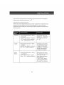
Selection Switch Settings Active Light
Mode
Constant Power Mode Selection = Setto Will light up when the
“Constant” amplifieris “On/Active”
Master Power Button = Pushto and will go off when it
“In” position to turn amplifier is “off”
“On” , out position is “Off”
Trigger Power Mode Selection = Set to Will light up only when
“Trigger” the amplifier receives a
Master Power Button = Leave in voltage indicating the
the “On” position (Button in amplifier is “Cn/Active”
Will turn off once the
voltage has stopped.
Audio Power Mode Selection = Setto Will light up only when
Sense “Audi Sense” the amplifier receives an
Master Power Button = Leave audio signal to the
inthe “On” position (Button in main inputs indicating
the amplifier is
“ON” /active. Will tu
off three minutes after
the signal has stopped.
13
INSTALLATION
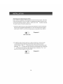
Selecting Inputs (See Diagrams 8 & 9)
Each channel is capable of delivering the source from many inputs. The three
main inputs are BUS, AUX and LINEIN. The selection for these inputs is done
via the Input Selection switch, marked “BUS-AUX-LINE” . To select a source
for each channel, followthe steps below:
1. Selectthe desired source input. Set the Input Selection switch to BUS (will
play source connected to the BUSINPUT), AUX (will play source connect-
ed to the AUX INPUT) or LINE (will play source connected to the LINEIN).
Ш | Diagram 8
BUS.AUX.LINE
2. The BUS and AUX inputs each have a left and right input. The left, right
or combined left and right signal fromthese may be selected viathe
switch marked “RR+LL" . Selectthe side you want the channel to deliver
Selecting “RR” + will play the right channel of the selected input. Selecting
“L™ will play the left channel of the selected input. Selecting “R+L" will
play the combined signals of right and left.
[Ш |
R R+L R
Diagram 9
14
INSTALLATION
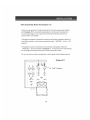
Selecting Bridge Mode (See Diagram 11)
Under normal operation, this should be left in the 8 ohm position as illustrat-
edin Diagram 10. It is sometimes desirable to combine two channels into
one through bridging. The output of the combined channels can then be
used to power one speaker.
To bridge two adjacent channels first make sure thatthe Impedance Switch is
inthe 8ohm position. Мех! move the switch marked “BRIDGE” tothe “ОМ”
position.
The speaker must be connected to the terminals immediately under the
“BRIDGED” textasindicatedin Diagram 11. All input selection and settings
for the bridged channels will be done on the channel to the left.
Do not connect more than one speaker to the outputs of the bridged channel.
« Diagram 11
a
@ 1, @
= x NE EN
eo. e = To “ON” Position
oe
и
E _EE—€E E e €
8) (e) ©
— vm
L L Ш
ERATE. E 5 EE
€ E E E
ni $n E Ш
= и yy | в ва, ©
i eg TE
“140
rima la |
i fen +.
1 p— mmm CANNEL. EAE.
— |
(+) (-)
Wires to Speaker
INSTALLATION
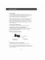
Control Output
The 12V output jack on the back of the amplifier can be used to turn on a
variety of components equipped to be activated when they receive a 12V DC
output. Voltage is only delivered to the jack when the amplifieris “on” or
active, When the amplifier turns off, the voltage ceases.
Before connecting another device to the 12 output please make sure that the
device canaccept12V DC at 150ma. To connect the output to another
device you must access the output jack with a two-conductor plug that fits
into the 3.5mm jack. Be aware that the tip of the plug will be (+). Ifyou are
unsure about using this feature please contact an authorized PYLE PRO
dealer for assistance.
Connecting the Speaker Wires
CAUTION: Only make connections when the amplifier is turned off.
Using Standard Connections (See Diagram 12)
For best performance use high quality speaker cables, The banana plug
outputs on the back of the amplifier allow for a variety of ways to con-
nect your speakers to the amplifier.
Diagram 12: Binding Post Detail
fa q Turn To Tighten
Insert Speaker Wire Insert Banana Plug
or Spade Connector
Connecting the Line Level Audio Inputs
CAUTION: Only make connections when the amplifier is turned off.
There are three areas that an input signal can be connected, BUS, AUX and
LINE IM. Refar to the System Design Examples to determine which is best suit-
ed for your application.
16
INSTALLATION
Audio Outputs
Sources connected to the “BUS” or "AUX" inputs can be forwarded to o
components or amplifiers by connecting to the corresponding output sections
to the right of each input section. By using standard audio patch cables, you
can connect these outputs to the inputs of another amplifier. Up to 5
SpeakerCraftamplifiers can be daisy-chained together.
AC Power
Plug the socket of the AC cord supplied with the amplifier into the receptacle
on the rear of the amplifier. Plug the Z prong plug directly into a 120V 60 Hz
wall outlet.
CAUTION: Do not plug the amplifier into the preamplifier or receivers
switched outlet. If you wish to have the amplifier turn on once the preamplifi-
erorrecelver is activated, use one of the turn on modes, voltage or audio.
OPERATION
See Diagram | for the location of the following:
Power Switch
The switch marked “Power” on the front panel of the amplifier will turn off a
amplifier circuitry no matter which turn on mode is selected, Refer to the
“Power Mode Selection” section for further information
Active LED
When lit, the Active LED indicates that the amplifier is operating. Refer to the
“Power Mode Selection” section of this manual for further information
Protection LEDs
When litthe “Protection” LEDs located on the front of the amplifier indica
that either a faultin the wiring, the speaker, or the amplifier has caused the
channels associated with the LED to shut down.
Level Adjustment Knobs
The level adjustment knobs on the back panel of the amplifier can be used to
adjust the level of each channel. There are many reasons for needing to
adjust the level. You many wish to closely match other levels in the system, or
you may wish to limit the volume level in an area, such as a child's room.
17
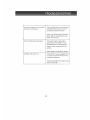
TROUBLESHOOTING
The amplifier is designed to function trouble-free. Most problems occur
because of operating errors. If you have a problem please check the trou-
bleshooting list first. Ifthe problem persists, contact your authorized
PYLE PRO customer service al (7 18)535-1800
The Problem Possible Causes And Solutions
Mo sound is heard on all channels. Audio cable to the source component
is not connected properly or the cable
is bad. Use another cable that you
know is good.
The Input Selection switch Is posi-
tioned incorrectly. Refer to installation
instructions for proper settings.
Some or all ofthe internal fuses are
blown. Return the amplifier to your
dealer for servicing.
Mo sound is heard on one or some Audio cable to the source component
channels. s not connected properly or the cable
s bad, Use another cable that you
know is good.
The Input Selection switch is posi-
tioned incorrectly. Refer to installation
nstructions for proper settings.
The Bridging switch is positioned
ncorrectly. Refer to installation instruc-
tions for proper settings.
Check the termination points ofthe
speaker cable at both the amplifier
and speaker. If using InstaL Lock
Connector, check the connections at
the levers.
A speaker is not working. Make sure
by connecting the channelto a
speaker that you know to be working.
Continuedon next page.)
TROUBLESHOOTING
No sound is heard on one or some | The level adjustment on the channel
channels. (Continued) is turned all the way down. Turn it
clockwise to raisa the volume.
some or all of the internal fuses are
blown. Return the amplifier to your
dealer for servicing.
Hum or buzzing sound is heard. The sound may be caused by a
ground loop in the system. Try to
eliminate this by reversing the AC
plugs of other components in the
system.
Other causes include faulty cables.
Amplifier will not turn on. The amplifier must be plugged into a
ive outlet. The power switch on the
ront panel must be on.
The Power Mode switch may be posi-
tioned incorrectly.
19
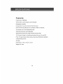
SPECIFICATIONS
Features:
Peak Power:1000Wx8
Three Color (L.E.D) Output Level Indicator
Bridgeable Amplifier
Independent Level Controls for Each Channel
Each Channel Can Be Set to Left, Right or Mono of the Bus,
Aux Inputs or it's Own Dedicated Input
Adjoining Channels are Bridgeable
Separate Protection Circuitry for Each Channel Pair
12V Control Output for Switching Auxiliary Devices On and Off
Pass Through Output Allows Daisy-Chaining of Multiple Amplifiers
5-Way Binding Posts
4U High
Dimensions: 19"w x19.2"hx7.2"d
Weight: 43.4 Ibs
20
PYLE
= PRO
PyleAudio.com
718.535.1800 718.236.2400 (fax)
1600 63rd Street, Brooklyn NY 11204