1
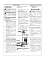
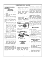
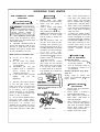
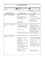
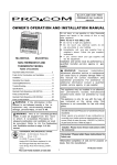
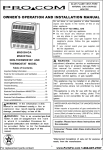
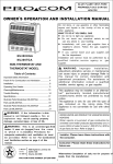
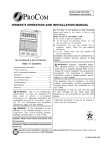
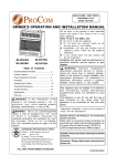
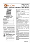
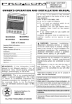
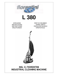
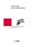
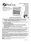
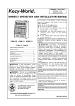
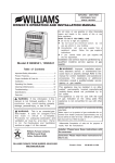
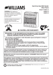
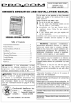
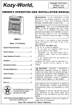
B LU E FL A ME V E NT -F RE E
NATURAL GA S G A R AG E
H EATE R
OWNER ’S OPERATION AND INSTALLATION MANUAL
MN300HGA
Do not store, or use gasoline or other flammable
vapors and liquids in the vicinity of this or any
other appliance.
WHAT TO DO IF YOU SMELL GAS
l Do not try to light any appliance.
l Do not touch any electrical switch; do not
use any phone in your building.
l Immediately call your gas supplier from a
neighbor’s phone. Follow the gas supplier’s
instructions.
l If you cannot reach your gas supplier, call
the fire department.
Installation and service must be performed by a
qu alified in stal ler, servic e a genc y or ga s
supplier.
MN300TGA
NON-THERMOSTAT AND
THERMOSTAT MODEL
Table of Contents
WAR N I N G : I m p ro p e r
i n st a l l a t i o n ,
adjustment, alteration, service or maintenance
can cause injury or property damage. Refer to
this manual f or correct installation and
operational procedures. For assistance or
additional information consult a qualif ied
installer, service agency, or gas supplier.
Important Safety Information..................................... 2
Fresh Air for Combustion and Ventilation ............... 4
Installation..................................................................... 8
Operating Your Heater............................................... 11
Cleaning&Maintenance.............................................13
Trouble Shooting.........................................................14
Specifications..............................................................17
This appliance may be installed in an aftermarket* permanent ly l ocated, m anuf act ured
(mobile) home, where not prohibited by local
codes.
This appliance is only for use with the type of
gas indicated on the rating plate. This
appliance is not convertible for use with other
gases.
Illustrate Parts Breakdown MN300TGA .................18
Parts List MN300TGA .................................................19
Illustrate Parts Breakdown MN300HGA .................20
Parts List MN300HGA .................................................21
WARNING: If the information in this
manual is not followed exactly, a fire o r
e x p l o s i o n m a y re s u l t causing property
damage, personal injury, or loss of life.
WATER VAPOR: A BY-PRODUCT OF UNVENTED ROOM
HEATERS
W ater vaporis a by-product of gas combustion.An
unvented room heater produces approximately one (1)
ounce (30ml) of water for every 1,000 BTU’s (.3KW ’s)
of gas input per hour. Refer to page 3.
WARNING: This is an unvented gas-fired
heater. It uses air (oxygen) f r o m t h e r o o m
i n w h i c h i t i s installed. Provisions for
adequate combustion and ventilation air must
b e p ro v i d e d . R e f e r t o A i r F o r Combustion
and Ventilation section on page 4 of this
manual.
Installer: Please leave these instructions with
the consumer.
CONTINENTAL APPLIANCE INC/U.S. OFFICE
5 Musick
4600 Highlands Parkway S.E.
Irvine
Suite # D/E
CA 92618
Smyrna, GA 30080
Consumer: Please retain these instructions for
future use.
Nanjing PRO-COM Electric Appliance Co.,Ltd.
*Aftermarket: Completion of sale, not for purpose of
resale, from the manufacturer.
#6 Chuangye Road,High New Tech.Zone,
Great Bridge Road North,Nanjing,210061,
China.
PRO-COM PHONE NUMBER: (877)886-5989
1
PR-ML062-09-0504
IMPORTANT
SAFETY INFORMATION
IM P O RTA N T: R ead t h is
owner’s manual carefully and
c o m p l e t e l y b e f o re t ryi n g t o
assem b le, op erat e, o r servic e
th is heat er. Im prop er use o f
this heater can cause serious
inj ury o r d eat h f ro m b urns,
fir e,
e xp lo sio n ,
ele c tric al
shock, and carbon m onoxide
poisoning.
WARNING: Do not use any
acc esso ry n o t app roved fo r
use with this heater.
WARNING: Any change to
this heater or its controls can
be dangerous.
Do not place clothing or other
flammable material on or near
the appliance. Never place any
objects on the heater.
Due to high temperatures, heater
should
be
k ep t
out
of
traffic and away from furniture
and draperies.
S u rfac e o f h eat er b ec o m es
very hot when running heater.
Keep children and adults away
from hot surface to avoid burns
or clothing ignition. Heater will
remain hot for a time after shut
d ow n. Allo w su rf ace to c oo l
before touching.
C ar ef u lly s u p e rvis e
yo u n g
children when they are in the
same room with heater.
Make sure grill gu ard is
place before running heater.
Keep the appliance area clear
a n d f r ee f r o m c o m b u s t i b l e
m at erials, gaso lin e, an d ot her
flammable vapors and liquids.
WARNING
Modeles MN300HGA, MN300TGA,
are equipped for natural gas. Field
conversion is not permitted.
1. This appliance is only for use
with the type of gas indicated
on the rating plate. This
appliance is not convertible for
use with other gases.
2. If you smell gas
l Shut off gas supply.
l Do not try to light any appliance.
l Do not touch any electrical switch;
l
l
3.
4.
5.
in
State of Massachusetts: The
installation must be made by a licensed plumber or gas fitter in the
Commonwealth of Massachusetts.
Sellers of unvented propane or natural gas-fired supplemental room heaters shall provide to each purchaser a
copy of 527 CMR 30 upon sale of the
unit.
In t he stat e o f M assac h u set ts,
unvented propane or nature gas-fired
space heaters shall be prohibited in
6.
7.
l
l
do not use any phone in your
building.
Immediately call your gas supplier
from a neighbor’s phone. Follow
the gas supplier’s instructions.
If you cannot reach your gas
supplier, call the fire department.
This heater shall not be
installed in a bedroom or
bathroom, or the place which
the strong wind would shut
down the appliance.
This heater needs fresh,
outside air ventilation to run
properly. This heater has an
Oxygen Depletion Sensor
(ODS) safety shutoff system.
The ODS shuts down the
heater if not enough fresh air
is available. See Fresh Air For
Combustion And Ventilation
pages 4 and 5.
Keep all air openings in the front
and bottom of heater clear
and free of debris. This will
insure enough air for proper
combustion.
If heater shuts off. Do not
relight until you provide fresh,
outside air. If heater keeps
shutting off, have it serviced.
Do not run heater
where flammable liquids or vapors
are used or stored
under dusty conditions
bedrooms and bathrooms.
2
8.
Turn heater off ,Before using
furniture polish, wax, carpet
cleaner, or similar products. If
heated, the vapors from these
products may create a white
powder residue within burner
box or on adjacent walls or
furniture.
9. Do not use heater if any part
has been under water.
Immediately call a qualified
service technician to inspect
the room heater and to
replace any part of the control
system and any gas control
which has been under water.
10. Turn off heater and let cool
before servicing. Only a
qualified service person should
service and repair heater.
11. Operating heater above elevations
of 4,500 feet could cause pilot
outage.
DANGER: Carbon monoxide
poisoning may lead to death!
Carbon Monoxide Poisoning:
Early signs of carbon monoxide
poisoning resemble the flu with
headaches, dizziness, or nausea.
If you have these signs, the heater
may not be working properly. Get
fresh air at once! Have heater
serviced. Some people are more
affected by carbon monoxide than
others. These include pregnant
women, persons with heart or lung
disease or anemia, those under the
influence of alcohol, and those
at high altitudes.
Natural Gas: Natural gas is odorless.
An odor-making agent is added to
natural gas. The odor helps you detect a natural gas leak . However,
the odor added to natural gas can
fade. Natural gas may be present
even though no odor
exists.
Make certain you read and understand all warnings. Keep this manual
for reference. It is your guide to safe
and proper operation of this heater.
PRODUCT FEATURES
Figure1-Vent-Free Natural Gas Heater(Model MN300TGA Shown)
SAFETY DEVICE
LOCAL CODES
A standard requirement for all vent-free room
heaters. This heater has a pilot with an Oxygen
Depletion Sensor(ODS) safety shutoff system.
The ODS/pilot shuts off the heater if there is
not enough fresh air.
Install and use heater with care. Follow all local
codes. In the absence of local codes, use the
latest edition of National Fuel Gas code ANSZ223.1,
also known as NFPA 54*.
*Available from :
American National Standards Institute, Inc.
1430 Broadway
New York, NY 10018
National Fire Protection Association, Inc.
Batterymarch Park
Quincy, MA 02269
PIEZO IGNITION SYSTEM
This heater is equipped with a piezo ignitor.
This system requires no matches, batteries, or
other sources to light heater.
THERMOSTATIC HEAT
CONTROL ON THERMOSTAT
MODEL MN300TGA
UNPACKING
1. Remove heater from carton.
2. Remove all protective packaging applied to
heater for shipment.
3. Check heater for any shipping damage. If heater
is damaged. promptly inform dealer where you
bought heater.
These heaters have a control valve with a
thermostat sensing bulb. This results in the
greatest heater comfort and may result in
lower gas bills.
WATER VAPOR: A BY-PRODUCT OF UNVENTED ROOM HEATERS
W ater vaporis a by-product of gas combustion.An unvented
room heater produces approximately one (1) ounce (30ml) of
water for every 1,000 BTU’s (.3KW ’s) of gas input per hour.
Unvented room heaters are remommended as supplemental
heat (a room) rather than a primary heat source (an entire
house) .In most supplemental heat application, the water
vapor does not create a problem. In most applications, the
water vapor enhances the low humidit y atmosp here
experience during cold weather.
3
The following steps will help insure that water
vapor does not become a problem.
1. Be sure the heater is sized properly for the
application, including ample combusion air and
circulation air.
2. If high humidity is experienced, a dehumidifier
may be used to help lower the water vapor content
of the air.
3. Do not use an unvented room heater as the
primary heat source.
FRESH AIR FOR
COMBUSTION AND
VENTILATION
WARNING: This heater
sh all no t b e in st alled in a
confined space or unusually
t ig h t
c o n st r u c t io n
u n less
provisions are pro vided f or
ad equ ate
com bu stion
and
ve n t i l at i o n a i r. R ea d t h e
follow in g
in s tr u c t io n s
to
insure proper fresh air for this
and
ot h er
f u el-bu rn in g
appliances in your home.
PRODUCING ADEQUATE
VENTILATION
The following are excerpts from
National Fuel Gas Code. NFPA 54/
ANS Z223.1, Section 5.3. Air for
Combustion and Ventilation. All
spaces in homes fall into one of
the three following ventilation
classifications:
1. Unusually Tight Construction
2. Unconfined Space
3. Confined Space
The information on pages 4
through 6 will help you classify
your space and provide adequate
ventilation.
Unusually Tight Construction
The air that leaks around doors and
windows may provide enough fresh
air for combustion and ventilation.
However, in buildings of unusually
tight construction, you must provide
additional fresh air.
Unusually tight construction is
defined as construction where:
a. walls and ceilings exposed to the
outside
atmosphere
have
a
continuous water vapor retarder
with a rating of one perm (6×10-11 kg
per pa-sec-m 2 )
o r less with
openings gasketed or sealed and
b. weather stripping has been
added on openable windows and
doors and
c. caulking or sealants are applied
to areas such as joints around
window and door frames, between
sole plates and floors, between
wall-ceiling joints, between wall
panels, at penetrations for plumbing,
electrical, and gas lines, and at
other openings. If your home meets
all of the three criteria above, you
must provide additional fresh air.
See Ventilation Air from Outdoors,
page 6.
If your home does not meet all of
th e th ree crit eria above, se e
Determining Fresh-Air Flow for
Heater Location, page 5
Confined and
Unconfined Space
The National Fuel Gas Code ANS
Z223.1 defines a confined space
as a space whose volume is less
than 50 cubic feet per 1,000 Btu per
h o u r ( 4 . 8 m 3 p er k w ) o f t h e
agg regate inpu t ratin g o f all
appliances installed in that space
and an unconfined space as a
space whose volume is not less
than 50 cubic feet per 1,000 Btu per
h o u r (4 . 8 m 3 p er k w ) o f t h e
agg regate inpu t ratin g o f all
appliances installed in that space.
Rooms communicating directly with
th e sp ac e in
w h ic h
the
appliances are installed*, through
openings not furnished with doors,
are considered a part of the
unconfined space.
This heater shall not be installed
in a confined space or unusually
tight
c o n s tru c t io n
u n le ss
p r o vi sio n s are p ro vid ed f o r
ad eq uate
co mb ustion
an d
ventilation air.
* A dj oining roo ms are
communicating only if there are
do orless
p assageways
or
ventilation grills between them.
DETERMINING FRESH-AIR FLOW FOR HEATER LOCATION
Determining if you have a Confined or Unconfined Space*
Use this worksheet to determine if you have a confined or unconfined space.
Space: Includes the room in which you will install heater plus any adjoining rooms with doorless passageways
or ventilation grills between the rooms.
1. Determine the volume of the space (length×width×height)
Length×Width×Height=
cu.ft. (volume of space)
Example: Space size 20ft. (length)×16ft.( width)×8ft. (ceiling height)=2560cu. ft. (volume of space)
If additional ventilation to adjoining room is supplied with grills or openings, add the volume of these
rooms to the total volume of the space.
2. Divide the space volume by 50 cubic feet to determine the maximum Btu/Hr the space can support.
(volume of space)÷ 50 cu. ft.=(Maximum Btu/Hr the space can support)
Example: 2560 cu. ft. (volume of space)÷50 cu.ft.=51.2 or 51.200(maximum Btu/Hr the space can support)
WARNING: If the area in which the heater may be operated is smaller than that defined as an
unconfined space or if the building is of unusually tight construction, provide adequate combustion and
ventilation air by one of the methods described in the National Fuel Gas Code, ANS Z223.1, Section 5.3
or applicable local codes.
4
3. Add the Btu/Hr of all fuel burning appliances in the space.
Vent-free heater
Btu/Hr
Gas water heater*
Btu/Hr
Example:
Gas furnace
Btu/Hr
Gas water heater
40,000
Btu/Hr
Vented gas heater
Btu/Hr
Vent free heater +
20,000
Btu/Hr
Gas Fireplace logs
Btu/Hr
Total
= 60,000
Btu/Hr
Other gas appliances* +
Btu/Hr
Total
=
Btu/Hr
*Do not include direct-vent gas appliances. Direct-vent draws combustion air from the outdoors and
vents to the outdoors.
4. Compare the maximum Btu/Hr the space can support with the actual amount of Btu/Hr used.
Btu/Hr (maximum the space can support)
Btu/Hr (actual amount of Btu/Hr used)
Example : 51,200 Btu/Hr(maximum the space can support)
60,000 Btu/Hr(actual amount of Btu/Hr used)
The space in the above example is a confined space because the actual Btu/Hr used is more than the
maximum Btu/Hr the space can support.
You must provide additional fresh air. Your options are as follows:
A. Rework worksheet, adding the space of an adjoining room. If the extra space provides an unconfined
space, remove door to adjoining room or add ventilation grills between rooms. See Ventilation Air From
Inside Building, page 5.
B. Vent room directly to the outdoors. See Ventilation Air From Outdoors, page 6 .
C. Install a lower Btu/Hr heater, if lower Btu/Hr size makes room unconfined.
If the actual Btu/Hr used is less than the maximum Btu/Hr the space can support, the space is an
unconfined space. You will need no additional fresh air ventilation.
VENTILATION AIR
Ventilation Air From Inside Building
This fresh air would come from an
adjoining unconfined space. W hen
ventilating to an adjoining unconfined
space, you must provide two permanent
openings: one within 12" of the ceiling
and one within 12" of the floor on the
wall connecting the two spaces (see
options 1 and 2, Figure 2). You can also
remove door into adjoining room (see
option 3, Figure 2). Follow the National
Fuel Gas Code NFPA 54/ANS Z223.1.
Section 5.3, Air for Combustion and
Ve n t i l a t i o n f o r re q u ire d size o f
ventilation grills or ducts
WARNING: Rework worksheet, addin g th e spac e of the ad j oining
unconfined space. The combined spaces
must have enough fresh air to supply all
appliances in both spaces.
Figure 2 -Ventilation Air from Inside Building
5
VENTILATION AIR
Ventilation Air From Outdoors
Provide extra f resh air b y using
ventilation grills or duels: You must
provide two permanent openings: one
within 12" of the ceiling and one within
12" of the floor.
Connect these items directly to the
outdoors or spaces open to the outdoors.
These spaces include attics and crawl
spaces. Follow the National Fuel Gas
Code NFPA 54/ANS Z223.1, Section 5.3.
Air for Combustion and Ventilation for
required size of ventilation grills or ducts.
IMPORTANT: Do not provide openings
for inlet or outlet air into attic if attic has
a thermostat-controlled power vent.
Heated air entering the attic will activate
the power vent.
Figure 3 -Ventilation Air from Outdoors
INSTALLATION
NOTICE: This heater is
intended for use as supplemental
heat. Use this heater along with
your primary heating system. Do
not install this heater as your
primary heat source. If you have
a central heating system, you
may run system’s circulating
blower while using heater. This
will help circulate the heat
throughout the house. In the
event of a power outage, you can
use this heater as your primary
heat source.
WARNING: A qualified
service person must install
heater. Follow all local codes.
CHECK GAS TYPE
Use only natural gas. If your gas
supply is not natural, do not install
heater. Call dealer w here you
bought heater for proper type heater.
INSTALLATION NEEDS
Before installing heater, make sure
you have the items listed below.
l piping (check local codes)
l sealant (resistant to natural
gas)
l
l
l
l
l
l
equipment shutoff valve*
ground joint union
test gauge connection*
sediment trap
*A CSA/AGA design-certified equipment shutoff valve with 1/8 " NPT
tap is an acceptable alternative to
test gauge connection. Purchase
the optional CSA/AGA design certified equipment shutoff valve from
your dealer. See Accessories, page
17.
LOCATING HEATER
This heater is designed to be
mounted on a wall. You can locate
heater on floor, away from a wall.
An optional floor mounting stand is
need ed. P urchase
th e
floor
mounting stand from your dealer.
See Accessories, page 17.
For convenience and efficiency,
install heater
l
where there is easy access for
operation, inspection, and service
l in coldest part of room
An optional fan kit is available from
your dealer. See Accessories,
page 17. If planning to use fan,
locate heater near an electrical
outlet.
CAUTION: If you install the
heater in a home garage
l heater pilot and burner must
be at least 18 inches above
floor.
l locate heater where moving
vehicle will not hit it.
tee joint
pipe wrench
6
CAUTION: This heater
creates warm air cu rrent s.
Th ese c urrents mo ve heat
t o w a ll
s u rf ac e s n ext t o
h e ate r. In s tallin g
h eater
next to vinyl or cloth wall
c overing s
or
o p e r at in g
heater where impurities (such as
tobacco smoke, aromatic candles,
cleaning fluids, oil or kerosene
lamps, etc.) in the air exist may
discolor walls.
the
l
l
l
l
l
l
WARNING: Never install
heater
in a bedroom or bathroom.
in a recreational vehicle.
where curtains, furniture,
clothing, or other flammable
objects are less than 36 inches
from the front, top, or sides
of the heater.
as a fireplace insert.
in high traffic areas.
in windy or drafty areas.
INSTALLATION
WARNING: Maintain the
minim um clearances sho wn
i n F i g u r e 4 . I f yo u c a n ,
provide greater clearances from
floor, ceiling, and joining wall.
FASTENING HEATER TO WALL
Mounting Bracket
The mounting bracket is located
on back panel of heater (see
figure 6). It has been taped there
fo r sh ip ping . Remo ve m ou nt in g
bracket from back panel.
Figure 6 -Mounting Bracket
Location
Figure 4 -Mounting Clearaances
As Viewed From Front Of Heater
IMPORTANT: Vent-free
heaters add moisture to the
air. Although this is beneficial,
in stallin g h eat er in ro o m s
without enough ventilation air
may cause mildew to
form
from too much moisture. See
Fresh Air for Combustion and
Ventilation, pages 4 and 5.
INSTALLING THERMOSTAT
SENSING BULB
For MN300TGA
1. Pull out the sensing bulb from the
two clips located in the shippng
position according to the direction
as shown by the arrow. There is no
need to take out the two bulb clips.
2. Take out the bulb clip from the
hardware package and insert it into
the square hole and then insert the
sensing bulb into the bulb clip (see
Figure 5).
Removing Lower Front Panel Of
Heater
1. Remove two screws near bottom
corners of lower front panel .
2. Pull bottom of lower front panel
forward, then down (see Figure 7).
Attaching to Wall Stud: This method
provides the strongest
hold. Insert
mounting screws through mounting
b rac k et and int o wall st ud s.
Attaching to Wall Anchor: This
m et ho d allow s you to att ac h
mounting bracket to hollow walls
(wall areas between studs) or to
solid walls (concrete or masonry).
Decide which method better
suits
your needs. Either method
will
provide a secure hold for the
mounting bracket.
Marking Screw Locations
1. Tape mounting bracket to wall
where heater will be located.
Make sure mounting bracket is
level.
WARNING:
Maintain
minimum clearances shown in
Figure 8. If you can, provide
greater clearances from floor
and joining wall.
2. Mark sc rew loc at io ns on
wall. (see Figure 8)
Note: Only mark last hole on
each end of mounting bracket.
Insert mounting screws through
these holes only.
3. Remove tape and mounting
bracket from wall.
Figure 7 - Removing Lower Front
Panel Of Heater
Methods For Attaching Mounting
Bracket To Wall
Only use last hole on each end
of mounting bracket to attach
bracket to wall. These two holes
are 16 inches apart from their
centers. Attach mounting bracket
to wall only in one of two ways:
1. Attaching to wall stud
2. Attaching to wall anchor
Figure 5 - Moving Thermostat
Sensing Bulb
7
Model MN300HGA MN300TGA
Figure 8 - Mounting Bracket
Clearances
INSTALLATION
Attaching Mounting Bracket to
Wall
Note: Wall anchors, mounting
screws, and spacers are in
hardware package. The hardware
package is provided with heater.
Attaching to Wal l Stud Method
For attaching mounting bracket to
wall studs
1. Drill holes at marked locations
using 9/64" drill bit.
2. Place mounting bracket onto
wall. Line up last hole on each
end of bracket with holes drilled
in wall.
3. Insert mounting screws through
bracket and into wall studs.
4. Tighten screws until mounting
bracket is firmly fastened to
wall studs.
Attaching to Wall Anchor
Method
For attaching mounting bracket to
hollow walls (wall areas between
studs) or solid walls. (concrete or
masonry)
1. Drill holes at marked locations
using 5/16" drill bit. For solid
walls (concrete or masonry),
drill at least 1" deep.
2. Fold wall anchor as shown in
Figure 9 below.
Figure 9 - Folding Anchor
3.
4.
Insert wall anchor (wings
first) into hole. Tap anchor
flush to wall.
For thin walls (1/2" or less),
insert red key into wall
anchor. Push red key to
"pop" open anchor wings.
IMPORTANT: Do not hammer key! For thick walls (over 1/
2 " t h i c k ) o r s o li d w all s,
do not pop open wings.
Figure 10 - Popping Open Anchor
Wing for Thin Walls
5. Place mounting bracket onto
wall. Line up last hole on
each end of bracket with wall
anchors.
6. Insert mounting screws through
bracket and into wall anchors.
7. Tighten screws until mounting
bracket is firmly fastened to
wall.
Placing Heater on Mounting
Bracket
1. Locate two horizontal slots on
back panel of heater (see
Figure 11).
2. Place heater onto mounting
bracket. Slide horizontal slots
onto stand-out
tabs
on
mounting bracket.
Figure 11 - Mounting Heater Onto
Mounting Bracket
Installing Bottom Mounting
Screws
1. Locate two bottom mounting
holes. These holes are near
bottom on
back panel of
heater(see Figure 12).
8
Figure 12 - Installing Bottom
Mounting Screws
2. Mark screw locations on wall.
3. Remove heater from mounting
bracket.
4. If installing bottom mounting
screws into hollow or solid wall,
install wall anchors. Follow steps
1 through 4 under Attaching To
Wall Anchor Method. If installing
bottom mounting screw into wall
stud, drill holes at marked
locations using 9/64" drill bit.
5. Replace heater onto mounting
bracket.
6. Place spacers between bottom
mounting holes and wall anchor
or drilled hole.
7. Hold spacer in place with
one
hand. W ith other hand, insert
mounting screw through bottom
mounting hole and
spacer. Place tip of screw in
opening of wall anchor or drilled
hole.
8. Tighten both screws until heater
is firmly secured to wall. Do not
over tighten.
l Note: Do not replace lower front
panel at this time. Replace lower
front panel after making gas
connections and checking for
leaks (see page 9).
INSTALLATION
CONNECTING TO GAS SUPPLY
WARNING: A qualified
service person must connect
heater to gas supply. Follow all
local codes.
WARNING: This appliance
requires a 3/8 " NPT (National
Pipe Thread) inlet connection
to the pressure regulator.
WARNING: Never connect
heater to private (non-utility) gas
well. This gas is commonly
known as well-head gas.
IMPORTANT: Check your gas line
pressure before connecting heater
to gas line. Gas line pressure must
be no greater than 14 inches of
water. If gas line pressure is higher,
heater regulator damage could
occur.
CAUTION: Use only new,
b la c k ir o n o r stee l p ip e.
Internally-tinned copper tubing
may be used in certain areas.
Check your local codes. Use pipe
of large enough diameter to
allow proper gas volume to heater.
If
p ip e
is
too
s m a ll ,
undue loss of pressure will
occur.
Typical Inlet Pipe Diameters
MN300HGA/MN300TGA 1/2” or
greater
Installation
mu st
inclu de an
equipment shutoff valve, union,
and plugged 1/8" NPT tap. Locate
NPT tap within reach for test gauge
hook up. NPT tap must be up
stream from heater (see Figure
13).
Figure 13 -Gas Connection
*A CSA/AGA design-certified equipment shutoff valve with 1/8" NPT tap is
an acceptable alternative to test gauge connection. Purchase the optional
C S A / A G A d es i g n - c e rt i f ie d e q u ip m e n t sh u t o f f va l ve f r o m
your dealer. See Accessories, page 17.
IMPORTANT: Install an equipment
shutoff valve in an accessible
location. The equipment shutoff
valve is for turning on or shutting
off the gas to the appliance.
Apply pipe joint sealant lightly to
male threads. This will prevent
excess sealant from going into
pipe. Excess sealant in pipe could
result in clogged heater valves.
CAUTION: Use pipe joint
sealant that is resistant to
natural gas.
9
Install sediment trap in supply line
as shown in Figure 13. Locate
sediment trap where it is within
reac h
f o r c lean in g . L o c at e
sediment
trap where trapped
matter is not likely to freeze. A
sediment trap traps moisture and
contaminants. This keeps them
from going into heater controls. If
sediment trap is not installed or is
in st alled w ro ng , h eat er m ay
not run properly.
IMPORTANT:
Hold pressure
reg u lat o r w ith w ren c h w h en
connecting it to gas piping and/or
fittings.
INSTALLATION
CHECKING GAS
CONNECTIONS
WARNING:
Test all gas
piping and connections for leaks after
installing or servicing. Correct all
leaks at once.
WARNING: Never use an open
flame to check for a leak. Apply a
mixture of liquid soap and water
to
all
joints. Bubbles forming
show a leak. Correct all leaks at
once.
Pressure Testing Gas Supply
Piping System
Test Pressures In Excess Of
1/2 PSIG (3.5 K Pa)
1. Disconnect appliance with its
appliance
main
gas valve
(control valve) and equipment
shutoff valve from gas supply
piping system. Pressures in
excess of 1/2 psig will damage
heater regulator.
2. Cap off open end of gas pipe
where equipment shutoff valve
was connected.
3. Pressurize
supply
piping
s ys t e m
by
e ith e r u s in g
compressed air or opening
main gas valve located on or
near gas meter.
4. Check all joints of gas supply
piping system. Apply mixture of
liquid soap and water to gas
joints. Bubbles forming show
a leak.
5. Correct all leaks at once.
6. Reconnect heater and equipment
shutoff valve to gas supply. Check
reconnected fittings for leaks.
OPERATING YOUR HEATER
Pressure Testing Heater Gas
Connections
1. Open equipment shutoff valve
(see Figure 14).
2. Open main gas valve located on
or near gas meter.
3. Make sure control knob of
heater is in the OFF position.
4. Check all joints from equipment
shutoff valve to control valve
(see Figure 15 ). Apply mixture of
liquid soap and water to gas
joints. Bubbles forming show
a leak.
5. Correct all leaks at once.
6. Light heater (see Operating
Heater, pages 11 for thermostat
m o d el o r
p ag e 1 2
for
non-thermostat model). Check
the rest of the internal joints for
leaks.
7. Turn off heater (see To Turn Off
Gas To Appliance, page 11 for
thermostat model or page 12
for non-thermostat model).
8. Replace lower front panel.
nFOR YOUR SAFETYn
READ BEFORE LIGHTING
WARNING: If you do not
f o llo w
t h ese
in st r u c t io n s
exactly, a fire or explosion may
r e su l t
c au s i n g
p r o p er t y
damage, personal injury
or
loss of life.
A. This appliance has a pilot which
must
be lighted by hand.
W hen lighting the pilot, follow
these instructions exactly.
B. BEFORE LIGHTING smell all
around the appliance area for
gas. Be sure to smell next to
the floor because some gas is
heavier than air and will settle
on the floor .
WHAT TO DO IF YOU SMELL GAS
l
l
l
l
Figure 14 -Equipment Shutoff Valve
Test Pressures Equal To or
Less Than 1/2 PSIG (3.5 K Pa)
Close equipment shutoff valve
(see Figure 14).
2. Pressurize supply piping system
by either using compressed air
or opening main gas valve
located on or near gas meter.
3. Check all joints from gas meter to
equipment shutoff valve (see
Figure 15). Apply mixture of
liquid soap and water to gas
joints. Bubbles forming show
a leak.
4. Correct all leaks at once.
THERMOSTAT MODEL
MN300TGA
1.
Figure 15 -Checking Gas Joints
WARING:Do not over tighten gas
connections.
10
Do not try to light any appliance.
Do not touch any electric switch;
do not use any phone in your
building.
Immediately
call
your gas
sup plier fro m a neighbo r’s
phone. Follow
the
gas
supplier’s instructions.
If you cannot reach your
gas supplier, call the fire
department.
C. Use only your hand to push in
or turn the gas control knob.
Never use tools. If the knob
will not push in or turn by
hand, don’t try to repair it, call
a qualified service technician or
gas supplier. Force or attempted
repair may result in a fire or
explosion.
D. Do not use this appliance if any
p art h as b ee n u n d er w at er.
Immediately call a qualified
service technician to inspect
the appliance and to replace
any part of the control system
and any gas control which has
been under water.
OPERATING YOUR HEATER
THERMOSTAT MODEL
MN300TGA
nLIGHTINGn
INSTRUCTIONS
1. STOP! Read
the safety
information on the side of
heater.
2. Check that gas supply to
heater is on.
3. Push in gas control knob
slightly and turn clockwise
to the OFF position.
NOTE: knob cannot be turned from
“PILOT” to “OFF” unless knob is
p u sh e d in s li g h t l y. D o n o t
force.
4. W ait five (5) minutes to clear
out any air. Then smell for
gas, including near the floor.
If
you
smell gas, STOP!
Follow “B”
in
the
safety
information on the side of the
heater. If you do not smell
gas, go to the next step.
5. Push
in gas control knob
slightly and turn
counterclockwise to the “PILOT/IGN”
po sit ion an d dep ress fo r
five(5) seconds
NOTE: The first time that the
h eater
is o p er at ed af te r
connecting the gas supply , the
control knob should be depressed
for about thirty (30) seconds. This
will allow air to bleed from the gas
system.
6. With control knob pressed in,
push down and release the
ignitor button. This will light
pilot. If needed, keep pressing
ignitor button until pilot lights.
NOTE: If pilot does not stay lit,
refer to Troubleshooting, pages 14
through 16. Also contact a qualified
service person or gas supplier for
repairs. Until repairs are made, light
pilot with match. To light pilot with
match, see Manual Lighting
Procedure.
7.
Keep control knob pressed in
for thirty (30) seconds after
lighting
pilot.
After
30
seconds, release control knob.
l If control knob does not pop
up when released, contact a
qualified
service person or
gas supplier for repairs.
NOTE: If pilot goes out, repeat
steps 3 through 7. W ait one (1)
minute before lighting pilot again
8. Turn
control
knob
counterclockwise
to
desired heating Level. The
main burner should light. Set
control knob to any heat level
between HI and LO.
Figure 16 - Control Knob in The
OFF Position
This increases or decreases the
burner flame height. At times the room
may exceed the set temperature. If
so, the burner will shut off. The burner
will cycle back on when room temperature drops below the set
temperature. The control knob can be
set to any heat level between HI and
LO. Selecting the HI setting will cause
the burner to remain fully on without
modulating down in most cases.
NOTE:
the thermostat sensing
bulb measures the temperature
of air near the heater cabinet.
This may not always agree with
ro o m t em p erat u re (d ep en d in g
on
hou sing
c o n s tr u c t io n .
installation location, room size,
o p en air t em perat u res, etc . ) .
frequent use of your heater will
let yo u determ in e yo ur ow n
comfort levels.
nTO TURN OFFn
GAS TO APPLIANCE
Shutting Off Heater
1. Turn control knob clockwise
2.
to the OFF position.
Turn off all electric power to
the appliance if service is to
be performed.
SHUTTING OFF BURNER ONLY
(PILOT STAYS LIT)
Turn control knob clockwise
to
the PILOT/IGN position
Figure 17 - Pilot
nMANUAL LIGHTINGn
PROCEDURE
nTHERMOSTATn
1.
CONTROL
OPERATION
2.
The thermostatic control used on
these models differs from standard
thermostats. Standard thermostats
simply turn on and off the burner.The
thermostat used on this heater
senses the room temperature. The
thermostat adjusts the amount
of gas flow to the
burner.
3.
4.
5.
11
Remove lower front panel (see
Figure 7 page 7).
Follow steps 1 through 5
under Lighting Instructions.
With control knob pressed in,
strike match. Hold match to
pilot until pilot lights.
Keep control knob pressed in
for 30 seconds after lighting
pilot. After 30 seconds, release
control knob. Follow step 8
under Lighting Instructions.
Replace lower front panel.
OPERATING YOUR HEATER
nLIGHTINGn
INSTRUCTIONS
NON-THERMOSTAT MODEL
MN300HGA
nFOR YOUR SAFETYn
READ BEFORE LIGHTING
2.
WARNING: If you do not
follow these instructions exactly,
a fire or explosion may result
causing property
damage,
personal injury or loss of life
3.
A.
This appliance has a pilot
which must be lighted by hand.
When lighting the pilot, follow these
instructions exactly.
B.
BEFORE LIGHTING smell all
around the appliance area for gas.
Be sure to smell next to the floor
because some gas is heavier than
air and will settle on the floor.
WHAT TO DO IF YOU SMELL GAS
l
l
l
l
1.
Do not try to light any
appliance.
Do not touch any electric
switch, do not use any phone
in your building.
Immediately call your gas
supplier from a neighbor’s
p h o n e. F o l lo w t h e g a s
supplier’s instructions.
If you cannot reach your gas
supplier,
call
the
fire
department.
C. Use only your hand to push in
or turn the gas control knob.
Never use tools. If the knob will
not push in or turn by hand, don’t
try to repair it , call a qualified
service technician or gas supplier.
Force or attempted repair may
result in a fire or explosion.
D. Do not use this appliance if any
p art h as b een u nd er w at er.
Immediately call a qualified service
t ec h n ic ia n t o in s p e c t th e
appliance and to replace any part of
the control system and any gas
control which has been under water.
4.
5.
STOP!
Read
the
safety
information on the side of heater.
Check
that gas supply to
heater is on.
Push in control knob slightly
and turn clockwise
to the
OFF position (see Figure 18).
NOTE: Knob cannot be turned
from "PILOT " to "OFF " unless
knob is pushed in slightly. Do
not force.
Wait five minutes to clear out
any gas. Then smell for gas,
including near the floor. If you
smell gas, STOP! Follow " B " in
the safety information on the side
of heater. If you don’t smell gas,
go to the
n ext
step.
Push in and turn control knob
counterclockwise
to PILOT
position. Press in control knob
for five(5) seconds.
Note: You may be running
this heater for the first time
after hooking up to gas supply.
If so, you may need to press
in control knob for 30 seconds.
This will allow air to bleed from
the gas system.
6.
7.
8.
With control knob pressed in,
push down and release the
ignitor button. This will light
pilot. If needed, keep pressing
ignitor button until pilot lights.
Keep control knob depressed
for ten (10) seconds after lighting
pilot. if pilot goes out, repeat
steps 5,6 and 7.
To select the desired heating
level, partially press down the
control knob slightly and rotate
counterclockwise
. Release
the downward pressure on the
knob while continuing to turn
until the knob locks at the
desired setting position. Do not
o p erat e
b et w een lo c k ed
positions.
nTOTURN OFFn
GAS TO APPLIANCE
Shutting Off Heater
1. Turn control knob clockwise
to the OFF position.
2. Turn off all electric power to
the appliance if service is to
be performed.
Shutting Off Burner Only (pilot
stays lit )
Slightly press in control turn
control knob clockwise
to the
PILOT position.
nMANUAL LIGHTINGn
Figure 18 - Control Knob in The
OFF Position
PROCEDURE
1.
2.
3.
4.
Figure 19 - Pilot
5.
12
Remove lower front panel (see
Figure 7 page 7).
Follow steps 1 through 5
under Lighting Instructions.
With control knob pressed in,
strike match. Hold match to
pilot until pilot lights.
Keep control knob pressed in
for 30 seconds after lighting
pilot. After 30 seconds, release
control knob. Follow step 8
under Lighting Instructions.
Replace lower front panel.
INSPECTING
BURNER
Check pilot flame pattern and
burner flame pattern often.
PILOT FLAME PATTERN
Figure 20 shows a correct pilot
flame pattern. Figure 21 shows an
incorrect pilot flame pattern. The
incorrect pilot flame is not touching
thermocouple. This will cause the
thermocouple to cool. W hen the
thermocouple cools, the heater will
shut down. If pilot flame pattern is
incorrect, as shown in Figure 21:
l
turn heater off (see To Turn
Off Gas To Appliance on page
12 for non-thermostat model or
page 11 for thermostat model)
l see Troubleshooting pages 14
through 16.
Figure 20 - Correct Pilot Flame
Pattern
BURNER FLAME PATTERN
Figure 22 shows a correct burner
flame pattern. Figure 23 shows an
incorrect burner flame pattern. If
pilot flame pattern is incorrect, as
shown in Figure 23:
l turn heater off (see To Turn Off
Gas To Appliance on page 12 for
non-thermostat model and page
11 for thermostat model).
l see Troubleshooting on pages 14
through 16.
WARNING: If yellow tipping
occurs, your heater could produce
in c reased levels o f c arb o n
monoxide. If burner flame pattern
shows yellow tipping, follow instructions at bottom of this page.
Notice: Do not mistake orange
flames with yellow tipping. Dirt or
other fine particles enter the heater
and burn causing brief
patches of orange flame.
Figure 22 - Correct Burner Flame
Pattern
Figure 23 - Incorrect Burner
Flame Pattern
Figure 21 - Incorrect Pilot Flame
Pattern
CLEANING ODS/PILOT AND
BURNER
l
Use a
vacuum cleaner,
pressurized air or a small, soft
bristled brush to clean.
CLEANING BURNER PILOT
AIR INLET HOLE
We recommend that you clean the
unit every 2,500 hours of operation or
every t hree mon ths. W e also
recommend that you keep the burner
tube and pilot assembly clean and free
of dust and dirt. To clean these parts
we recommend using compressed
air no greater than
30 PS l.
Your local computer store, hardware
store. or home center may carry compressed air in a can. You can use a
vacuum cleaner in the blow position. If
using compressed air in a can, please
follow the directions on the can. If you
don’t follow directions on the can, you
could damage the pilot assembly.
1. Shut off the unit, including thepilot
Allow the unit to cool for
at least thirty minutes.
2. Inspect burner and pilot for dust
and dirt.
3. Blow air through the ports/slots
and holes in the burner.
Also, clean the pilot assembly . A
yellow tip on the pilot flame indicates dust and dirt in the pilot
assembly. There is a small pilot air
inlet hole about two inches from
where the pilot flame comes out of
the pilot assembly (see Figure 24).
With the unit off lightly blow air through
the air inlet hole. You may blow through
a drinking straw if
compressed air is
not available.
CLEANING AND
MAINTENANCE
WARNING : Turn off heater
and let cool before servicing.
CAUTION: You must keep control
areas, burner, and circulating air
passageways of heater clean. Inspect these
areas of heater before each use. Have
heater Inspected yearly by a qualified
service person. Heater may need more
frequent cleaning due to excessive lint
f r om carpeting,
bedding
material, pet hair, etc.
13
Figure 24 - Pilot Inlet Air Hole
CLEANING HEATER CABINET
Air Passageways
l Use a
vacuum cleaner or
pressurized air to clean.
Exterior
l Use a soft cloth dampened with
a mild soap and water mixture.
Wipe the cabinet to remove dust.
TROUBLESHOOTING
Note :
All
troubleshooting
items are listed in order of
operation.
WARNING: Only a qualified
service person should service and
repair heater.
OBSERVED PROBLEM
When ignitor button is pressed in,
there is no spark at ODS/pilot.
POSSIBLE CAUSE
1. Ignitor electrode is positioned
wrong.
2. Ignitor electrode is broken.
3. Ignitor electrode is not connected
to ignitor cable.
4. Ignitor cable pinched or wet.
5. Broken ignitor cable.
6. Bad piezo ignitor.
When ignitor button is pressed in,
there is a spark at ODS/pilot but no
ignition.
1 . G as su p p ly t u rn ed o f f o r
equipment shutoff valve is closed.
2. Control knob not fully pressed in
while pressing ignitor button.
3. Air in gas lines when installed.
4.
ODS/pilot is clogged.
5. Gas regulator setting is not correct
6. Control knob not in PILOT position.
ODS/pilot lights but flame goes out
when control knob is released.
1. Control knob is not fully pressed
in.
2. Control knob is not pressed in
long enough.
3. Equipment shutoff valve is not
fully open.
4. Thermocouple connection is loose
at control valve.
5 Pilot flame is not touching thermocouple, This allows
thermocouple
to cool, causing
pilot flame to go out.
This problem could be caused
by one or both of the following:
A) Low gas pressure.
B) Dirty
or
partially clogged
ODS/pilot.
6. Thermocouple damaged.
7. Control valve damaged.
14
CAUTION: Never use a wire,
needle, or similar object to clean
ODS/pilot. This can damage
ODS/pilot unit.
REMEDY
1. Replace ignitor.
2. Replace ignitor.
3. Reconnect ignitor cable.
4. Free ignitor cable if pinched by
any
metal or tubing. Keep
ignitor cable dry.
5. Replace ignitor cable.
6. Replace piezo ignitor.
1. Turn on gas supply or open
equipment shutoff valve.
2. Fully press in control knob
while pressing ignitor button.
3. Continue holding down control
knob. Repeat igniting operation
until air is removed.
4. Clean ODS/pilot (see Cleaning
and Maintenamce, Page 13) or
replace ODS/pilot assembly.
5. Replace gas regulator.
6. Turn control knob to PILOT position.
1. Press in control knob fully.
2. After ODS/pilot lights, keep control
knob pressed in 30 seconds.
3. Fully open equipment shutoff valve.
4. Hand tighten until snug, then
tighten 1/4 turn more.
5. A) Contact local natural gas
company.
B) Clean ODS/pilot (see Cleaning
and Maintenance, Page 13) or
replace ODS/pilot assembly.
6. Replace thermocouple.
7. Contact Dealer or PRO-COM.
TROUBLESHOOTING
Continued
OBSERVED PROBLEM
POSSIBLE CAUSE
B u rn er(s)d o es n o t lig h t a f t er
ODS/pilot is lit.
1.
REMEDY
Burner orifice is clogged.
2. Burner orifice diameter is too small.
3. Inlet gas pressure is too low.
Delayed ignition of burner(s).
1. Manifold pressure is too low.
2. Burner orifice is clogged.
Burner backfiring during combustion.
1. Burner orifice
damaged.
is clogged
1. Contact local natural gas company.
2. Clean burner (see Cleaning and
Maintenance, Page 13) or replace
burner orifice.
or
2. Burner is damaged.
3. Gas regulator is defective.
Yellow flame during burner
combustion.
1. Not enough air.
2. Gas regulator defective.
3. Inlet gas pressure is too low .
Slight smoke or
initial operation.
odor
during
Heater produces a whistling noise
when burner is lit.
1. Clean burner orifice (see Cleaning
and Maintenance, Page 13) or
replace burner orifice.
2. Replace burner orifice.
3. Contact local natural gas company.
1. Residues from manufacturing
processes
.
1. Turning control knob to HI position
when burner is cold.
2. Air in gas line.
3. Air passageways on heater are
blocked.
4. Dirty or partially clogged burner
orifice.
1. Clean burner orifice (see Cleaning
and Maintenance, Page 13) or
replace.
2. Contact Dealer or PRO-COM.
3. Replace gas regulator.
1. Check burner for dirt and debris.
If found, clean burner(see Cleaning
And Maintenance, Page 13).
2. Replace gas regulator.
3. Contact local natural gas company.
1. Problem will stop after a few hours
of operation.
1. Turn control knob to LO position
and let warm up for a minute.
2. Operate burner until air is removed
from line. Have gas line checked
by local natural gas company.
3. Observe
minimum installation
clearances (see Figure 4, page 7).
4. Clean burner (see Cleaning and
Maintenance, Page 13) or replace
burner orifice.
Heater produces a clicking/ticking
noise just after burner is lit or
shut off.
1. Metal is expanding while heating
or contracting while cooling.
1. This is common with most
heaters. if noise is excessive,
contact qualified service person.
White powder residue forming within
burner box or on adj ac ent
walls or furniture.
1. When heated the vapors from
furniture polish, wax, carpet
cleaners, etc. turn into white
powder residue.
1. Turn heater off when using
furniture polish, wax, carpet
cleaner, or similar products.
15
TROUBLESHOOTING
Continued
WARNING: If you smell gas
l
l
l
l
Shut off gas supply.
l
If you cannot reach your gas supplier, call the fire department.
Do not try to light any appliance.
Do not touch any electrical switch; do not use any phone in your building.
Immediately cal l your gas supplier from a neighbor’s phone. Follow the gas
supplier’s instructions.
IMPORTANT : Operating heater where impurities in air exist may create odors. Cleaning supplies, paint, paint remover, cigarette smoke, cements and glues, new carpet or
textiles, etc, create fumes. These fumes may mix with combustion air and create odors.
POSSIBLE CAUSE
OBSERVED PROBLEM
Heater produces unwanted odors.
Heater shuts off in use (ODS operates).
1. Heater is burning vapors from
paint, hair spray, glues, etc.
(See IMPORTANT statement
above).
2 . G as le ak . S ee W a rn in g
Statement at top of page.
1.
Ventilate room. Stop using odor
causing products while heater
is running.
2.
Locate and correct all leaks(see
Checking Gas Connections,
Page 10).
1.
Not enough fresh air is available.
1.
2.
Low line pressure.
3. ODS/pilot is partially clogged.
Gas odor exists even when control
knob is in OFF position.
Gas odor during combustion.
Moisture/condensation
windows.
noticed
on
REMEDY
Open window and/or door for
ventilation.
2. Contact local natural gas
company.
3. Clean ODS/pilot (see Cleaning
Page 12).
1. Gas leak. See W arning
Statement at top of page.
1.
2. Control valve is defective.
2.
1.
Foreign matter between control
valve and burner.
2. Gas
leak.
See Warning
Statement at top of page.
1.
1.
1.
Not enough combustion/ventilation
air.
16
2.
Locate and correct all leaks(see
Checking Gas Connections,
Page 10).
Contact Dealer or PRO-COM
Take apart gas tubing and
remove foreign matter.
Locate and correct all leaks
(see
Checking
Gas
Connections, Page 10).
Refer to Air for Combustion and
Ventilation requirements, Page
4.
SPECIFICATIONS
Btu(available)
Gas Type
Ignition
Pressure Regulator Setting
Inlet Gas Pressure (inches of water)
Maximum
Minimum
Dimensions, Inches (HxWxD)
Heater
Carton
Weight (pounds)
Heater
Shipping
MN300HGA
15,000/30,000
Natural Only
Piezo
3" W.C.
MN300TGA
14,000/30,000
Natural Only
Piezo
3"W.C
10.5 "
4"
10.5 "
4"
23 1/2×26 5/8×8
26 1/2×28 1/2×91/4
23 1/2×26 5/8×8
26 1/2×28 1/2×91/4
26
31
26
31
Note: Dimensions listed are outer most points on the heater (includes control knobs and grill).
* For purposes of input adjustment.
REPLACEMENT PARTS
ACCESSORIES
Note: Use only original replacement
parts. This will protect your warranty
coverage for parts replaced under
warranty.
Purchase these heater accessories
from your local dealer. If they can
not supply these accessories,
contact PRO-COM for information.
You can also write to the address
listed on the back page of this
manual.
PARTS UNDER WARRANTY
Contact authorized dealer from
whom you purchased this product.
If they are unable to supply original
replacement part(s), call the number
on the back of this manual. When
contacting your dealer or PRO-COM,
have ready:
l your name
l your address
l model and serial numbers of
your heater
l how heater was malfunctioning
l type of gas used (propane/LP or
natural gas)
l purchase date
l Warranty Card
Usually, we will ask you to return the
defective part to the factory.
FAN PF06-YJLF-B
EQUIPMENT SHUTOFF VALVE
PARTS NOT UNDER
WARRANTY
Contact authorized dealers of this
product. If they can’t supply
original replacement part(s), contact
PRO-COM.
For all models, provides better heat
distribution. Makes heater or efficient.
Complete installation and operating
instructions included.
Thermostatically-controlled PF06YJLF-B, includes three settings
ON/OFF/AUTO
For all models. Equipment shutoff
valve with 1/8" NPT tap. This part
is not currently available from
PRO-COM.
TECHNICAL SERVICE
You may have further questions
about installation, operation, or
troubleshooting. If so, contact
PRO-COM.The information is listed
on the back of manual.
17
ILLUSTRATED PARTS
BREAKDOWN
MN300TGA
ODS/Pilot Assembly
18
PARTS LIST
MN300TGA
This list contains replaceable parts for your heater. When ordering replacement
parts, follow the instructions listed under Replacement Parts on page17 of this
manual.
KEY
NO.
1
2
3
4
5
6
7
8
9
10
11
12
13
14
15
16
17
18
19
20
21
22
23
24
24_1
24_2
25
26
27
MN300TGA
PART NO.
QTY
MB10052
MB09052
MB11052
ML089-01
ML157-01
MB29001
ML069-02
SIT545-250
845-4.8x60Z
ML111-01
ML083-03
ML073-01
NRV81FI-3
96-4Z
ML079-01
MB40006
MB40022
MB40023
NBB30-000B1
ML101-01
ML091-02
ML103-01
ML104-01
ND1103x800x9
ND0803-8
ND0807
ML105-03
6170-5Z
ML060-01
DESCRIPTION
Cabinet Assembly
Lower Front Panel Assembly
Reflector Unit
Steel Wind Shield
Middle Panel
Grill Guard Assembly
Self Tapping Screw
Thermostat Valve Assembly
Screws
Thermostat Valve Base/Bracket
Ignitor Assembly
Ignitor Line
Pressure Regulator
Washer
Self Locking Screw
Main Inlet Tube Assembly
ODS Line Assembly
Burner Inlet Tube Assembly
Burner
Burner connector
Injector
Left Burner Support Bracket
Right Burner Support Bracket
ODS/pilot Assembly
Thermocouple
Ignitor Electrode
ODS Upper Deflector
Nut
Mounting Bracket
MB28001
ML070-27
ML071-01
ML072-01
ML065-01
Assembly Hardware
AGA/CSA Label
Gas Instruction Decal
Inside Warning Label
Thermostat Sensing Bulb Clip
1
1
1
1
2
19
1
1
1
1
1
1
12
1
2
1
1
1
1
2
2
1
1
1
1
1
1
1
1
1
1
1
1
2
1
ILLUSTRATED PARTS
BREAKDOWN
MN300HGA
ODS/Pllot Assembly
20
PARTS LIST
MN300HGA
This list contains replaceable parts for your heater. W hen ordering replacement parts, follow the instructions listed under Replacement Parts on page17
of this manual.
KEY
NO.
MN300HGA
PART NO.
DESCRIPTION
QIY
1
2
3
4
5
6
7
8
9
10
11
12
13
14
15
16
17
18
19
20
21
22
23
24
25
26
27
28
28-1
28-2
29
30
31
MB10053
MB09051
MB11052
ML089-01
MB29001
ML157-01
ML083-03
ML069-02
NV2020-14
ML073-01
MB16002
ML029-01
NRV81FI-3
96-4Z
ML079-01
MB40016
MB40018
MB40019
MB40020
MB40021
ML096-01
MB40017
NBB30-000B1
ML101-01
ML091-01
ML103-01
ML104-01
ND1103x800x9
ND0803-8
ND0807
ML105-03
6170-5Z
ML060-01
Cabinet Assembly
Lower Front Panel Assembly
Reflector Unit
Steel Wind Shield
Grill Guard Assembly
Middle Panel
Ignitor Assembly
Self Tapping Screw
Control Valve
Ignitor Line
Control Knob
Control Valve Fixed Nut
Pressure Regulator
Washer
Self Locking Screw
Main Inlet Tube Assembly
ODS Line Assembly
Lower Gas Outline Tube Assembly
Medium Gas Outline Tube Assembly
High Gas Outline Tube Assembly
4-Way Connector
Burner Inlet Tube Assembly
Burner
Burner Connector
Injector
Left Burner Support Bracket
Right Burner Support Bracket
ODS/pilot Assembly
Thermocouple
Ignitor Electrode
ODS Upper Deflector
Nut
Mounting Bracket
1
1
1
1
1
1
1
12
1
1
1
1
1
2
2
1
1
1
1
1
1
1
1
1
1
1
1
1
1
1
1
2
1
MB28001
ML160-25
ML071-01
ML072-01
ML065-01
Assembly Hardware
AGA/CSA Label
Gas Instruction Decal
Inside Warning Label
Thermostat Sensing Bulb Clip
1
1
1
1
2
21