1
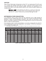
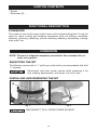
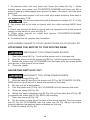
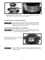
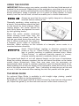
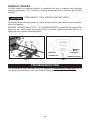
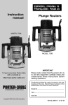
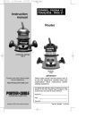
Instruction
manual
ESPAÑOL: PÁGINA 17
FRANÇAISE : PAGE 31
Router
MODEL
100
To learn more about Porter-Cable
visit our website at:
http://www.porter-cable.com
IMPORTANT
Please make certain that the person who is
to use this equipment carefully reads and
understands these instructions before
starting operations.
The Model and Serial No. plate is located on the main
housing of the tool. Record these numbers in the
spaces below and retain for future reference.
Model No. ______________________________________
Type ___________________________________________
Serial No. _______________________________________
Copyright © 2004 Porter-Cable Corporation
Part No. 907395 - 12-15-04
TABLE OF CONTENTS
IMPORTANT SAFETY INSTRUCTIONS . . . . . . . . . . . . . . . . . . . . . . . . . .2
SAFETY GUIDELINES . . . . . . . . . . . . . . . . . . . . . . . . . . . . . . . . . . . . . . . .3
GENERAL SAFETY RULES . . . . . . . . . . . . . . . . . . . . . . . . . . . . . . . . . . .4
ADDITIONAL SPECIFIC SAFETY RULES . . . . . . . . . . . . . . . . . . . . . . . .6
CARTON CONTENTS . . . . . . . . . . . . . . . . . . . . . . . . . . . . . . . . . . . . . . . .9
FUNCTIONAL DESCRIPTION . . . . . . . . . . . . . . . . . . . . . . . . . . . . . . . . .9
OPERATION . . . . . . . . . . . . . . . . . . . . . . . . . . . . . . . . . . . . . . . . . . . . . . .9
TROUBLESHOOTING . . . . . . . . . . . . . . . . . . . . . . . . . . . . . . . . . . . . . .13
MAINTENANCE . . . . . . . . . . . . . . . . . . . . . . . . . . . . . . . . . . . . . . . . . . . .14
SERVICE . . . . . . . . . . . . . . . . . . . . . . . . . . . . . . . . . . . . . . . . . . . . . . . . .14
ACCESSORIES . . . . . . . . . . . . . . . . . . . . . . . . . . . . . . . . . . . . . . . . . . . .15
WARRANTY . . . . . . . . . . . . . . . . . . . . . . . . . . . . . . . . . . . . . . . . . . . . . . .15
ESPAÑOL . . . . . . . . . . . . . . . . . . . . . . . . . . . . . . . . . . . . . . . . . . . . . . . . .17
FRANÇAISE . . . . . . . . . . . . . . . . . . . . . . . . . . . . . . . . . . . . . . . . . . . . . . .31
SERVICE CENTER LOCATIONS . . . . . . . . . . . . . . . . . . . . . . .back cover
IMPORTANT SAFETY INSTRUCTIONS
Read and understand all warnings and operating instructions
before using any tool or equipment. When using tools or equipment, basic safety
precautions should always be followed to reduce the risk of personal injury.
Improper operation, maintenance or modification of tools or equipment could
result in serious injury and property damage. There are certain applications for
which tools and equipment are designed. Porter-Cable strongly recommends that
this product NOT be modified and/or used for any application other than for
which it was designed.
If you have any questions relative to its application DO NOT use the product
until you have written Porter-Cable and we have advised you.
Online contact form at www.porter-cable.com
Postal Mail: Technical Service Manager
Porter-Cable Corporation
4825 Highway 45 North
Jackson, TN 38305
Information regarding the safe and proper operation of this tool is available from
the following sources:
Power Tool Institute
1300 Sumner Avenue, Cleveland, OH 44115-2851
www.powertoolinstitute.org
National Safety Council
1121 Spring Lake Drive, Itasca, IL 60143-3201
American National Standards Institute, 25 West 43rd Street, 4 floor, New York, NY
10036 www.ansi.org ANSI 01.1Safety Requirements for Woodworking
Machines, and the U.S. Department of Labor regulations www.osha.gov
SAVE THESE INSTRUCTIONS!
2
SAFETY GUIDELINES - DEFINITIONS
It is important for you to read and understand this manual. The
information it contains relates to protecting YOUR SAFETY and
PREVENTING PROBLEMS. The symbols below are used to help
you recognize this information.
indicates an imminently hazardous situation which, if not
avoided, will result in death or serious injury.
indicates a potentially hazardous situation which, if not
avoided,could result in death or serious injury.
indicates a potentially hazardous situation which, if not
avoided,may result in minor or moderate injury.
used without the safety alert symbol indicates potentially
hazardous situation which, if not avoided, may result in
property damage.
CALIFORNIA PROPOSITION 65
Some dust created by power sanding, sawing, grinding, drilling,
and other construction activities contains chemicals known (to the
State of California) to cause cancer, birth defects or other reproductive harm. Some
examples of these chemicals are:
● lead from lead-based paints
● crystalline silica from bricks and cement and other masonry products
● arsenic and chromium from chemically-treated lumber
Your risk from these exposures varies, depending on how often you do this type
of work. To reduce your exposure to these chemicals: work in a well ventilated
area, and work with approved safety equipment, always wear NIOSH/OSHA
approved, properly fitting face mask or respirator when using such tools.
3
GENERAL SAFETY RULES
Read all instructions. Failure to follow all
instructions listed below may result in electric shock, fire and/or
serious injury. The term "power tool" in all of the warnings listed
below refers to your mains-operated (corded) power tool or
battery-operated (cordless) power tool.
SAVE THESE INSTRUCTIONS
1) Work area safety
a) Keep work area clean and well lit. Cluttered or dark areas invite
accidents.
b) Do not operate power tools in explosive atmospheres, such as in the
presence of flammable liquids, gases or dust. Power tools create
sparks which may ignite the dust or fumes.
c) Keep children and bystanders away while operating a power tool.
Distractions can cause you to lose control.
2) Electrical safety
a) Power tool plugs must match the outlet. Never modify the plug in any
way. Do not use any adapter plugs with earthed (grounded) power
tools. Unmodified plugs and matching outlets will reduce risk of electric
shock.
b) Avoid body contact with earthed or grounded surfaces such as
pipes, radiators, ranges and refrigerators. There is an increased risk of
electric shock if your body is earthed or grounded.
c) Do not expose power tools to rain or wet conditions. Water entering a
power tool will increase the risk of electric shock.
d) Do not abuse the cord. Never use the cord for carrying, pulling or
unplugging the power tool. Keep cord away from heat, oil, sharp
edges or moving parts. Damaged or entangled cords increase the risk
of electric shock.
e) When operating a power tool outdoors, use an extension cord
suitable for outdoor use. Use of a cord suitable for outdoor use reduces
the risk of electric shock.
3) Personal safety
a) Stay alert, watch what you are doing and use common sense when
operating a power tool. Do not use a power tool while you are tired
or under the influence of drugs, alcohol or medication. A moment of
inattention while operating power tools may result in serious personal
injury.
b) Use safety equipment. Always wear eye protection. Safety equipment
such as dust mask, non-skid safety shoes, hard hat, or hearing
protection used for appropriate conditions will reduce personal injuries.
c) Avoid accidental starting. Ensure the switch is in the off-position
before plugging in. Carrying power tools with your finger on the switch
or plugging in power tools that have the switch on invites accidents.
4
GENERAL SAFETY RULES
continued
d) Remove any adjusting key or wrench before turning the power tool
on. A wrench or a key left attached to a rotating part of the power tool
may result in personal injury.
e) Do not overreach. Keep proper footing and balance at all times. This
enables better control of the power tool in unexpected situations.
f) Dress properly. Do not wear loose clothing or jewelry. Keep your
hair, clothing and gloves away from moving parts. Loose clothes,
jewelry or long hair can be caught in moving parts.
g) If devices are provided for the connection of dust extraction and
collection facilities, ensure these are connected and properly used.
Use of these devices can reduce dust-related hazards.
4) Power tool use and care
a) Do not force the power tool. Use the correct power tool for your
application. The correct power tool will do the job better and safer at the
rate for which it was designed.
b) Do not use the power tool if the switch does not turn it on and off.
Any power tool that cannot be controlled with the switch is dangerous
and must be repaired.
c) Disconnect the plug from the power source before making any
adjustments, changing accessories, or storing power tools. Such
preventive safety measures reduce the risk of starting the power tool
accidentally.
d) Store idle power tools out of the reach of children and do not allow
persons unfamiliar with the power tool or these instructions to
operate the power tool. Power tools are dangerous in the hands of
untrained users.
e) Maintain power tools. Check for misalignment or binding of moving
parts, breakage of parts and any other condition that may affect the
power tools operation. If damaged, have the power tool repaired
before use. Many accidents are caused by poorly maintained power
tools.
f) Keep cutting tools sharp and clean. Properly maintained cutting tools
with sharp cutting edges are less likely to bind and are easier to control.
g) Use the power tool, accessories and tool bits etc., in accordance
with these instructions and in the manner intended for the
particular type of power tool, taking into account the working
conditions and the work to be performed. Use of the power tool for
operations different from those intended could result in a hazardous
situation.
5) Service
a) Have your power tool serviced by a qualified repair person using
only identical replacement parts. This will ensure that the safety of the
power tool is maintained.
5
ADDITIONAL SPECIFIC SAFETY RULES
1.
2.
3.
4.
5.
6.
7.
8.
9.
10.
11.
12.
13.
14.
15.
16.
17.
18.
19.
HOLD POWER TOOL BY INSULATED GRIPPING SURFACES WHEN
PERFORMING AN OPERATION WHERE THE CUTTING TOOL MAY
CONTACT HIDDEN WIRING OR ITS OWN CORD. Contact with a "live"
wire will make exposed metal parts of the tool "live" and shock the operator.
USE CLAMPS OR OTHER PRACTICAL WAY TO SECURE AND SUPPORT
THEWORKPIECE TO A STABLE PLATFORM. Holding the work by hand or
against your body is unstable and may lead to loss of control.
DISCONNECT TOOL FROM POWER SOURCE before making adjustments
or changing bits.
TIGHTEN COLLET NUT securely to prevent the bit from slipping.
USE A CLAMP or some other device to hold the workpiece rigidly in position.
and clear the path of the tool of obstructions.
PROVIDE CLEARANCE under workpiece for router bit when throughcutting.
CHECK TO SEE THAT THE CORD will not “hang up” during routing
operation.
CLEAR THE ROUTER BIT AREA before starting motor.
MAINTAIN FIRM GRIP on router to resist starting torque.
KEEP HANDS CLEAR OF BIT when motor is running to prevent personal
injury.
KEEP CUTTING PRESSURE CONSTANT. Do not overload motor.
LET THE MOTOR COME TO A COMPLETE STOP before putting the tool
down.
NEVER TOUCH router bits after use. They may be extremely hot.
NEVER TIGHTEN COLLET NUT without a bit.
DO NOT USE ROUTER BITS with a diameter in excess of 2-1/2" at RPM
above 13,000. Router bits up to 3-1/2" in diameter can be used when speed
control is set for 13,000 RPM or less.
ALWAYS KEEP CHIP SHIELD clean and in place.
AVOID “CLIMB-CUTTING” (see “Using The Router” section in this manual).
“Climb-cutting” increases the chance for loss of control resulting in possible
personal injury.
DO NOT HAND-HOLD THE ROUTER IN AN UPSIDE-DOWN OR
HORIZONTAL POSITION. The motor can separate from the base if not
properly attached according to the instructions.
USE OF THIS TOOL CAN GENERATE AND DISBURSE
DUST OR OTHER AIRBORNE PARTICLES, INCLUDING WOOD DUST,
CRYSTALLINE SILICA DUST AND ASBESTOS DUST. Direct particles
away from face and body. Always operate tool in well ventilated area and
provide for proper dust removal. Use dust collection system wherever
possible. Exposure to the dust may cause serious and permanent
respiratory or other injury, including silicosis (a serious lung disease), cancer,
and death. Avoid breathing the dust, and avoid prolonged contact with dust.
Allowing dust to get into your mouth or eyes, or lay on your skin may
promote absorption of harmful material. Always use properly fitting
NIOSH/OSHA approved respiratory protection appropriate for the dust
exposure, and wash exposed areas with soap and water.
SAVE THESE INSTRUCTIONS!
6
SYMBOL
V
........................
A
........................
Hz
........................
W
........................
kW
........................
F
........................
µF
........................
l
........................
g
........................
kg
........................
bar
........................
Pa
........................
h
........................
min
........................
s
........................
n
........................
…/min or …min-1 .........
0
DEFINITION
volts
amperes
hertz
watts
kilowatts
farads
microfarads
litres
grams
kilograms
bars
pascals
hours
minutes
seconds
no-load speed
Revolutions or reciprocations per minute
or d.c. ............... direct current
or a.c. ................ alternating current
2
2N
3
3N
........................ two-phase alternating current
........................ two-phase alternating current with neutral
........................ three-phase alternating current
........................ three-phase alternating current with neutral
........................ rated current of the appropriate fuse-link in amperes
........................ time-lag miniature fuse-link where X is the symbol
for the time/current characteristic, as given in IEC 60127
........................ protective earth
IPXX
........................ class II tool
........................ IP symbol
7
MOTOR
Many Porter-Cable tools will operate on either D.C., or single phase 25 to 60 cycle
A.C. current and voltage within plus or minus 5 percent of that shown on the
specification plate on the tool. Several models, however, are designed for A.C.
current only. Refer to the specification plate on your tool for proper voltage and
current rating.
Do not operate your tool on a current on which the
voltage is not within correct limits. Do not operate tools rated A.C.
only on D.C. current. To do so may seriously damage the tool.
EXTENSION CORD SELECTION
If an extension cord is used, make sure the conductor size is large enough to
prevent excessive voltage drop which will cause loss of power and possible motor
damage. A table of recommended extension cord sizes will be found in this
section. This table is based on limiting line voltage drop to 5 volts (10 volts for 230
volts) at 150% of rated amperes.
If an extension cord is to be used outdoors, it must be marked with the suffix WA or W following the cord type designation. For example – SJTW-A to indicate it
is acceptable for outdoor use.
Nameplate Ampere Rating
RECOMMENDED EXTENSION CORD SIZES FOR USE WITH PORTABLE ELECTRIC TOOLS
115V
230V
25 Ft.
50 Ft.
50 Ft.
100 Ft.
0-2
2-3
3-4
4-5
5-6
6-8
8-10
10-12
12-14
14-16
16-18
18-20
18
18
18
18
18
18
18
16
16
16
14
14
18
18
18
18
16
16
14
14
12
12
12
12
Length of Cord in Feet
100 Ft. 150 Ft. 200 Ft. 250 Ft.
200 Ft. 300 Ft. 400 Ft. 500 Ft.
18
16
16
14
14
12
12
10
10
10
8
8
16
14
14
12
12
10
10
8
8
8
8
6
16
14
12
12
10
10
8
8
6
6
6
6
14
12
12
10
10
8
8
6
6
6
4
4
SAVE THESE INSTRUCTIONS!
8
300 Ft.
600 Ft.
14
12
10
10
8
6
6
6
6
4
4
4
400 Ft. 500 Ft.
800 Ft. 1000 Ft.
12
10
10
8
8
6
6
4
4
4
2
2
12
10
8
8
6
6
4
4
2
2
2
2
CARTON CONTENTS
* Router
* Wrenches (2)
FUNCTIONAL DESCRIPTION
FOREWORD
The router is one of the most useful tools in the woodworking field. It may be
used for many cutting and shaping operations such as slotting, mortising,
dadoing, grooving, rabbeting, corner-rounding, beading, dovetailing, veining,
inlay work, etc.
OPERATION
NOTE: This tool is shipped completely assembled. No assembly time or
tools are required.
SELECTING THE BIT
This Router comes with a 1/4" split type collet which accommodates bits with
1
/4" shanks.
Disconnect tool from power source while preparing it for
use, making adjustments, and when it is not in use.
INSTALLING AND REMOVING THE BIT
B
A
Fig. 2
Fig. 1
DISCONNECT TOOL FROM POWER SOURCE.
9
1. To remove motor unit from base unit: Open the clamp (A) Fig. 1. While
holding base, turn power unit COUNTERCLOCKWISE until lower pin (B) in
motor housing is disengaged from groove in base. Lift power unit free from
base unit.
2. Clean and insert shank of bit into collet until shank bottoms, then back it
out approximately 1/16".
Do not use router bits with a diameter in excess of 1.5" in this
tool.
3. Lay power unit on its side on bench with the collet pointing AWAY from
you.
4. Place one wrench on flats of chuck with the opposite end of the wrench
resting on the bench to your left (Fig. 2).
5. Place other wrench on collet and tighten COUNTERCLOCKWISE.
TIGHTEN FIRMLY.
6. To remove the bit, reverse the procedure.
AVOID POSSIBLE DAMAGE TO COLLET. NEVER TIGHTEN COLLET WITHOUT BIT.
ATTACHING THE MOTOR TO THE ROUTER BASE
DISCONNECT TOOL FROM POWER SOURCE.
1. Open the clamp (A) Fig. 1 and set the power unit in the base unit.
2. Align the lower pin of the power unit (B) Fig. 1 with the groove in the base.
3. Rotate the power unit CLOCKWISE into the base until the upper guide
pins are set in the groove of the base.
4. Close the clamp.
ADJUSTING DEPTH OF CUT
DISCONNECT TOOL FROM POWER SOURCE.
1. Open the clamp (A) Fig. 3A.
2. Hold the base (E) and turn the power unit (F) Fig. 3A COUNTER-CLOCKWISE until the tip of the bit is above the bottom of the base.
3. Set the tool on a flat surface.
4. Turn the power unit (F) Fig. 3A CLOCKWISE until bit touches the work.
5. Close the clamp (A) Fig. 3A.
6. Rotate the depth adjusting ring (B) Fig. 3A until the zero-line (C) Fig. 3B
is opposite the index line (D) Fig. 3B on the housing.
7. Open the clamp (A) Fig. 3A.
8. Tip the router so that the bit is clear of the wood surface. Turn the power
unit (F) Fig. 3A CLOCKWISE until the index line (D) Fig. 3B on the motor
housing reaches the desired depth indicated on the ring.
9. Close the clamp (A) Fig. 3A.
10
F
B
E
D
C
A
Fig. 3A
Fig. 3B
NOTE: Setting the index line to 1/4" on the ring means the cutting
edge of the bit is exposed 1/4" below the base.
CONNECTING TO POWER SOURCE
Before connecting tool to power source ALWAYS MAKE
SURE SWITCH IS IN THE “OFF” POSITION. Also check
that the power circuit is the same as that shown on
specification plate of the router.
STARTING AND STOPPING THE MOTOR
Before starting the router, make sure that the bit is clear
of the workpiece and foreign objects. Keep a firm grip
on router to resist starting torque.
A
Start and stop the motor by setting
the toggle switch (A) Fig. 4 to the
“ON” or “OFF” position.
Fig. 4
To avoid personal injury or damage to finished work, always
allow the motor to come to a COMPLETE STOP before
setting it down.
11
USING THE ROUTER
IMPORTANT: Before using your router, consider the kind and total amount of
material to be removed. Depending on the workpiece, more than one cut may
be necessary to avoid overloading the motor. Before beginning the cut on the
actual workpiece, make a sample cut on a piece of scrap lumber to show
exactly how the cut will look, as well as enable you to check dimensions.
Always be sure that the work is rigidly clamped or otherwise
secured before making a cut.
Generally speaking, when working on
a bench, the workpiece should be held
on the bench by wood clamps. When
routing edges, the router should be
held firmly down and against the work
by both guiding knobs.
Since the cutter rotates clockwise
(when viewing router from top), the
router should be moved from left to
right as you stand facing the work (see
Fig. 5
Fig. 5). When working on the inside of
a templet, move router in clockwise
direction. When working on the outside of a templet, move router in a
counterclockwise direction.
Avoid “Climb-Cutting” (cutting in direction opposite that
shown in Fig. 5). “Climb-Cutting” increases the chance for
loss of control resulting in possible personal injury. When
“Climb-Cutting” is required (backing around a corner),
exercise extreme caution to maintain control of router.
The speed and depth of cut will depend largely on the type of workpiece.
Keep the cutting pressure constant, but do not crowd the router so the motor
speed slows excessively. More than one pass may be necessary on
exceptionally hard woods or problem materials to get the desired depth of cut.
When making cuts on all four edges of the workpiece, make the first cut on the
end of the piece across the grain. Thus, if chipping of wood occurs at the end
of a cut, it will be removed when making the next cut parallel with the grain.
THE EDGE GUIDE
An optional Edge Guide is available to aid straight edge planing, parallel
grooving, and dado or slotting operations.
To assemble, insert guide rods (A) in holes in base Fig. 6 and secure with screws
(B). Adjust the guide (C) on the rods and secure it with thumb screws (D).
12
TEMPLET GUIDES
A wide variety of templet guides is available for use in pattern and templet
routing operations. Fig. 7 shows a typical combination bit, templet guide, and
locknut.
DISCONNECT TOOL FROM POWER SOURCE.
To install, insert templet guide in center hole of router base and secure in place
with the locknut.
BEFORE CONNECTING TOOL TO POWER SOURCE, install the bit, adjust the
depth of cut, and rotate the router chuck by hand. Make sure that the bit or
collet do not contact templet guide.
B
A
D
ROUTER
BASE
B
LOCKNUT
SUB-BASE
ROUTER BIT
C
Fig. 6
TEMPLET GUIDE
Fig. 7
TROUBLESHOOTING
For assistance with your tool, visit our website at www.porter-cable.com for a
list of service centers or call the Porter-Cable help line at 1-800-487-8665.
13
MAINTENANCE
KEEP TOOL CLEAN
Periodically blow out all air passages with dry compressed air. All plastic parts
should be cleaned with a soft damp cloth. NEVER use solvents to clean plastic
parts. They could possibly dissolve or otherwise damage the material.
Wear ANSI Z87.1 safety glasses while using compressed air.
FAILURE TO START
Should your tool fail to start, check to make sure the prongs on the cord plug are
making good contact in the outlet. Also, check for blown fuses or open circuit
breakers in the line.
LUBRICATION
This tool has been lubricated with a sufficient amount of high grade lubricant for
the life of the unit under normal operating conditions. No further lubrication is
necessary.
BRUSH INSPECTION (If applicable)
For your continued safety and electrical protection, brush inspection and
replacement on this tool should ONLY be performed by an AUTHORIZED
PORTER-CABLE SERVICE STATION or a PORTER-CABLE•DELTA FACTORY
SERVICE CENTER.
At approximately 100 hours of use, take or send your tool to your nearest
authorized Porter-Cable Service Station to be thoroughly cleaned and inspected.
Have worn parts replaced and lubricated with fresh lubricant. Have new brushes
installed, and test the tool for performance.
Any loss of power before the above maintenance check may indicate the need for
immediate servicing of your tool. DO NOT CONTINUE TO OPERATE TOOL
UNDER THIS CONDITION. If proper operating voltage is present, return your tool
to the service station for immediate service.
SERVICE
REPLACEMENT PARTS
When servicing use only identical replacement parts. For a service parts list or
to learn more about Porter-Cable visit our website at www.porter-cable.com
SERVICE AND REPAIRS
All quality tools will eventually require servicing, or replacement of parts due to
wear from normal use. For assistance with your tool, visit our website at
www.porter-cable.com for a list of service centers or call the Customer Care
Department at 1-800-487-8665. All repairs made by our service centers are fully
guaranteed against defective material and workmanship. We cannot guarantee
repairs made or attempted by others.
Should you have any questions about your tool, feel free to write us at any time.
In any communications, please give all information shown on the nameplate of
your tool (model number, type, serial number, etc.).
14
ACCESSORIES
A complete line of accessories is available from your Porter-Cable•Delta
Supplier, Porter-Cable•Delta Factory Service Centers, and Porter-Cable
Authorized Service Stations. Please visit our Web Site www.porter-cable.com
for a catalog or for the name of your nearest supplier.
Since accessories other than those offered by
Porter-Cable•Delta have not been tested with this product, use of
such accessories could be hazardous. For safest operation, only
Porter-Cable•Delta recommended accessories should be used with
this product.
WARRANTY
PORTER-CABLE LIMITED
ONE YEAR WARRANTY
Porter-Cable warrants its Professional Power Tools for a period of one year from the date of original
purchase. We will repair or replace at our option, any part or parts of the product and accessories
covered under this warranty which, after examination, proves to be defective in workmanship or
material during the warranty period. For repair or replacement return the complete tool or accessory,
transportation prepaid, to your nearest Porter-Cable Service Center or Authorized Service Station.
Proof of purchase may be required. This warranty does not apply to repair or replacement required
due to misuse, abuse, normal wear and tear or repairs attempted or made by other than our Service
Centers or Authorized Service Stations.
ANY IMPLIED WARRANTY, INCLUDING THE IMPLIED WARRANTIES OF MERCHANTABILITY AND
FITNESS FOR A PARTICULAR PURPOSE, WILL LAST ONLY FOR ONE (1) YEAR FROM THE DATE
OF PURCHASE.
To obtain information on warranty performance please write to: PORTER-CABLE CORPORATION,
4825 Highway 45 North, Jackson, Tennessee 38305; Attention: Product Service. THE FOREGOING
OBLIGATION IS PORTER-CABLE’S SOLE LIABILITY UNDER THIS OR ANY IMPLIED WARRANTY
AND UNDER NO CIRCUMSTANCES SHALL PORTER-CABLE BE LIABLE FOR ANY INCIDENTAL OR
CONSEQUENTIAL DAMAGES. Some states do not allow limitations on how long an implied warranty
lasts or the exclusion or limitation of incidental or consequential damages, so the above limitation or
exclusion may not apply to you.
This warranty gives you specific legal rights and you may also have other legal rights which vary from
state to state.
15
NOTES
16
PORTER-CABLE • DELTA SERVICE CENTERS
(CENTROS DE SERVICIO DE PORTER-CABLE • DELTA)
(CENTRE DE SERVICE PORTER-CABLE • DELTA)
Parts and Repair Service for Porter-Cable • Delta Power Tools are Available at These Locations
(Obtenga Refaccion de Partes o Servicio para su Herramienta en los Siguientes Centros de Porter-Cable • Delta)
(Locations où vous trouverez les pièces de rechange nécessaires ainsi qu’un service d’entretien)
ARIZONA
Tempe 85282 (Phoenix)
2400 West Southern Avenue
Suite 105
Phone: (602) 437-1200
Fax: (602) 437-2200
GEORGIA
Forest Park 30297 (Atlanta)
5442 Frontage Road,
Suite 112
Phone: (404) 608-0006
Fax: (404) 608-1123
CALIFORNIA
Ontario 91761 (Los Angeles)
3949A East Guasti Road
Phone: (909) 390-5555
Fax: (909) 390-5554
ILLINOIS
Addison 60101 (Chicago)
400 South Rohlwing Rd.
Phone: (630) 424-8805
Fax: (630) 424-8895
San Diego 92111
7638 Clairemont Blvd.
Phone: (858) 277-9595
Fax: (858) 277-9696
Woodridge 60517 (Chicago)
2033 West 75th Street
Phone: (630) 910-9200
Fax: (630) 910-0360
San Leandro 94577 (Oakland)
3039 Teagarden Street
Phone: (510) 357-9762
Fax: (510) 357-7939
MARYLAND
Elkridge 21075 (Baltimore)
7397-102 Washington Blvd.
Phone: (410) 799-9394
Fax: (410) 799-9398
COLORADO
Arvada 80003 (Denver)
8175 Sheridan Blvd., Unit S
Phone: (303) 487-1809
Fax: (303) 487-1868
FLORIDA
Davie 33314 (Miami)
4343 South State Rd. 7 (441)
Unit #107
Phone: (954) 321-6635
Fax: (954) 321-6638
MINNESOTA
Minneapolis 55429
5522 Lakeland Avenue North
Phone: (763) 561-9080
Fax: (763) 561-0653
Cleveland 44125
8001 Sweet Valley Drive
Unit #19
Phone: (216) 447-9030
Fax: (216) 447-3097
MISSOURI
North Kansas City 64116
1141 Swift Avenue
Phone: (816) 221-2070
Fax: (816) 221-2897
OREGON
Portland 97230
4916 NE 122 nd Ave.
Phone: (503) 252-0107
Fax: (503) 252-2123
St. Louis 63119
7574 Watson Road
Phone: (314) 968-8950
Fax: (314) 968-2790
PENNSYLVANIA
Willow Grove 19090 (Philadelphia)
520 North York Road
Phone: (215) 658-1430
Fax: (215) 658-1433
NEW YORK
Flushing 11365-1595 (N.Y.C.)
175-25 Horace Harding Expwy.
Phone: (718) 225-2040
Fax: (718) 423-9619
NORTH CAROLINA
Charlotte 28270
9129 Monroe Road, Suite 115
Phone: (704) 841-1176
Fax: (704) 708-4625
MASSACHUSETTS
Franklin 02038 (Boston)
Franklin Industrial Park
101E Constitution Blvd.
Phone: (508) 520-8802
Fax: (508) 528-8089
MICHIGAN
Madison Heights 48071 (Detroit)
30475 Stephenson Highway
Phone: (248) 597-5000
Fax: (248) 597-5004
OHIO
Columbus 43214
4560 Indianola Avenue
Phone: (614) 263-0929
Fax: (614) 263-1238
TEXAS
Carrollton 75006 (Dallas)
1300 Interstate 35 N, Suite 112
Phone: (972) 446-2996
Fax: (972) 446-8157
Houston 77043
4321 Sam Houston Parkway, West
Suite 180
Phone: (713) 983-9910
Fax: (713) 983-6645
WASHINGTON
Auburn 98001(Seattle)
3320 West Valley HWY, North
Building D, Suite 111
Phone: (253) 333-8353
Fax: (253) 333-9613
Tampa 33609
4538 W. Kennedy Boulevard
Phone: (813) 877-9585
Fax: (813) 289-7948
Authorized Service Stations are located in many large cities. Telephone 800-487-8665 or 731-541-6042 for assistance locating one. Parts and
accessories for Porter-Cable • Delta products should be obtained by contacting any Porter-Cable • Delta Distributor, Authorized Service Center,
or Porter-Cable • Delta Factory Service Center. If you do not have access to any of these, call 888-848-5175 and you will be directed to the
nearest Porter-Cable • Delta Factory Service Center. Las Estaciones de Servicio Autorizadas están ubicadas en muchas grandes ciudades. Llame
al 800-487-8665 ó al 731-541-6042 para obtener asistencia a fin de localizar una. Las piezas y los accesorios para los productos Porter-Cable
• Delta deben obtenerse poniéndose en contacto con cualquier distribuidor Porter-Cable • Delta, Centro de Servicio Autorizado o Centro de
Servicio de Fábrica Porter-Cable • Delta. Si no tiene acceso a ninguna de estas opciones, llame al 888-848-5175 y le dirigirán al Centro de
Servicio de Fábrica Porter-Cable • Delta más cercano. Des centres de service agréés sont situés dans beaucoup de grandes villes. Appelez au
800-487-8665 ou au 731-541-6042 pour obtenir de l’aide pour en repérer un. Pour obtenir des pièces et accessoires pour les produits PorterCable • Delta, s’adresser à tout distributeur Porter-Cable • Delta, centre de service agréé ou centre de service d’usine Porter-Cable • Delta. Si
vous n’avez accès à aucun de ces centres, appeler le 888-848-5175 et on vous dirigera vers le centre de service d’usine Porter-Cable • Delta le
plus proche.
CANADIAN PORTER-CABLE • DELTA SERVICE CENTERS
ALBERTA
Bay 6, 2520-23rd St. N.E.
Calgary, Alberta
T2E 8L2
Phone: (403) 735-6166
Fax: (403) 735-6144
MANITOBA
1699 Dublin Avenue
Winnipeg, Manitoba
R3H 0H2
Phone: (204) 633-9259
Fax: (204) 632-1976
BRITISH COLUMBIA
8520 Baxter Place
Burnaby, B.C.
V5A 4T8
Phone: (604) 420-0102
Fax: (604) 420-3522
ONTARIO
505 Southgate Drive
Guelph, Ontario
N1H 6M7
Phone: (519) 767-4132
Fax: (519) 767-4131
QUÉBEC
1515 Ave.
St-Jean Baptiste, Suite 160
Québec, P.Q.
G2E 5E2
Phone: (418) 877-7112
Fax: (418) 877-7123
1447, Begin
St-Laurent, (Mtl), P.Q.
H4R 1V8
Phone: (514) 336-8772
Fax: (514) 336-3505
The following are trademarks of PORTER-CABLE • DELTA (Las siguientes son marcas registradas de PORTER-CABLE • DELTA S.A.) (Les marques
suivantes sont des marques de fabriquant de la PORTER-CABLE • DELTA): Auto-Set®, BAMMER®, B.O.S.S.®, Builder’s Saw®, Contractor’s Saw®,
Contractor’s Saw II™, Delta®, DELTACRAFT®, DELTAGRAM™, Delta Series 2000™, DURATRONIC™, Emc²™, FLEX®, Flying Chips™, FRAME
SAW®, Grip Vac™, Homecraft®, INNOVATION THAT WORKS®, Jet-Lock®, JETSTREAM®, ‘kickstand®, LASERLOC®, MICRO-SET®, Micro-Set®, MIDI
LATHE®, MORTEN™, NETWORK™, OMNIJIG®, POCKET CUTTER®, PORTA-BAND®, PORTA-PLANE®, PORTER-CABLE®&(design), PORTERCABLE®PROFESSIONAL POWER TOOLS, PORTER-CABLEREDEFINING PERFORMANCE™, Posi-Matic®, Q-3®&(design), QUICKSAND®&(design),
QUICKSET™, QUICKSET II®, QUICKSET PLUS™, RIPTIDE™&(design), SAFE GUARD II®, SAFE-LOC®, Sanding Center®, SANDTRAP®&(design),
SAW BOSS®, Sawbuck™, Sidekick®, SPEED-BLOC®, SPEEDMATIC®, SPEEDTRONIC®, STAIR EASE®, The American Woodshop®&(design), The
Lumber Company®&(design), THE PROFESSIONAL EDGE®, THE PROFESSIONAL SELECT®, THIN-LINE™, TIGER®, TIGER CUB®, TIGER SAW®,
TORQBUSTER®, TORQ-BUSTER®, TRU-MATCH™, TWIN-LITE®, UNIGUARD®, Unifence®, UNIFEEDER™, Unihead®, Uniplane™, Unirip®, Unisaw®,
Univise®, Versa-Feeder®, VERSA-PLANE® , WHISPER SERIES®,
WOODWORKER’S CHOICE™.
Trademarks noted with ™ and ® are registered in the United States Patent and Trademark Office and may also be registered in other countries.
Las Marcas Registradas con el signo de ™ y ® son registradas por la Oficina de Registros y Patentes de los Estados Unidos y también pueden
estar registradas en otros países. Marques déposées, indiquées par la lettre ™ et ®, sont déposées au Bureau des brevets d’invention et
marques déposées aux Etats-Unis et pourraient être déposées aux autres pays.
7.2-PTG-F-1