1
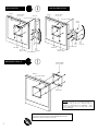
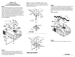
FLAT PANEL MOUNT
Each mount comes with two VESA mounting plates – one combination of 75/100 (mm) and one 75 (mm)-only plate for smaller mounting surfaces.
All Prestige flat panel mounts easily support most VESA-standard LCD flat panels on the market today.
PRF FLAT PANEL MOUNT
Features: Mount comes in both VESA 75 and VESA-100 models. Stands
.750" off the wall.
Lbs: 1
Description
Qty
Size
Wood screws
Anchors
Handy box screws
Monitor screws
Security screws
Monitor screws
Nylon spacers
4
4
2
4
2
4
4
#10 x 1-1/4"
#10
6-32 x 1"
M4 x 10 (mm)
M6 x 12 (mm)
M4 x 20 (mm)
.5"
HARDWARE
NOTE: If the screws (supplied) require being longer than M4 x 10 (mm) for your
monitor, use commercially available (suitable hardware) to complete your
installation.
NOTE: For monitors with a recessed VESA 75 use the four M4 x 20 (mm) Phillips
screws and the .5" nylon spacers (supplied).
PRF
1
IN-PRF.R1
WARNING!
The wall should be capable of supporting a weight of at least 50 lbs. If it cannot, the wall must be reinforced. Proper installatio
procedure by qualified personnel as outlined in the installation instructions must be adhered to. Failure to do so could result i
serious personal injury. It is strongly recommended that two people perform the installation procedures.
CAUTION! The entire installation instructions should be fully read and understood, including all of the safety symbols an
safety precautions, before beginning installation. The installation instructions should be read, understood and followed to preven
personal injury or property damage. Keep these installation instructions in an easily accessible location for future reference.
Indicates that the power plug is to be disconnected
from the power outlet.
Safety precautions must be taken at all times.
Warning and caution in general
INSTALLATION INSTRUCTIONS
PRF
Step 1
Check that you have all the hardware listed on the front of the page. If any of the hardware described is missing on your particular model do not
continue, contact PREMIER MOUNTS INC. shown on the front cover.
Separate the plates and choose the location for the monitor and follow any safety and precautions from the monitor’s manufacturer.
Single studs: For single wood studs use the two (2) middle mounting points found on the back plate. Locate the center of the wood stud behind
the wall, mark the height and location desired. Drill two (2) 1/8" pilot holes on the marked wall. Secure the back plate to the center of the wood
stud by using two (2) of the #10 wood screws (supplied). All electrical wiring should be done at this time use the two (2) 6-32 x 1" handy box
screws (supplied) for your installation needs. Secure the front plate to the monitor using the four (4) M4 x 10 (mm) Phillip screws (supplied). The
flange opening must be facing up and the flat surface touching the flat panel surface. Raise the monitor with the front plate attached and slip the
top flange opening to the flange on the back plate. Slide the monitor down slowly. Make sure the back plate flange captures the front plate top
flange opening before letting go of the monitor. Slide down and push in. To secure the two plates install the two (2) M6 x 12 (mm) securing
screws to the bottom of the plates using a long Phillip head screwdriver.
Solid structure: Use the four (4) mounting points on the back plate. Choose the wall where the monitor will be located. Level and mark with a
pencil the four (4) mounting points found on the back plate. Drill four (4) 1/16" pilot holes for the plastic anchors then secure the wall bracket
with the four (4) #10 x 1¼" screws (supplied) to the anchors. All electrical wiring should be done at this time use the two (2) 6-32 x 1" handy box
screws (supplied) for your installation needs. Secure the front plate to the monitor. The flange opening must be facing up and the flat surface
touching the monitor surface. Secure using the four (4) M4 x
10 (mm) Phillip screws (supplied). Raise the flat panel with the front plate attached and slip the top flange opening to the flange on the back
plate. Slide the monitor down slowly. Make sure the back plate flange captures the front plate top flange opening before letting go of the monitor.
Slide down and push in. To secure the two plates install the two (2) M6 x 12 (mm) securing screws to the bottom of the plates using a long
Phillip head screwdriver.
Recessed monitor: If you have a recessed VESA 75 the four (4) .5" nylon spacers and the four (4) M4 x 20 (mm) Phillips must be used to follow
the single stud
Or the solid structure installation methods to complete the installation.
CAUTION:
Do not over tighten the M4 screws to the monitor. Failure to do so could result in damaging the threads and
monitor.
2
SINGLE STUD
monitor
SOLID STRUCTURE
monitor
monitor screws
M4 x 10 (mm)
wood stud
monitor screws
M4 x 10 (mm)
electrical opening
electrical opening
plastic
anchors
back
plate
back
plate
front plate
M6 x 12 (mm)
security screws
solid
wall
structure
#10 wood screw RECESSED VESA 75
solid
wall
structure
#10 wood screw front plate
M6 x 12 (mm)
security screws
monitor screws
M4 x 20 (mm)
monitor
.5" nylon spacers
front plate
NOTE: Use the four (4) .5" nylon spacers and four (4)
M4 x 20 (mm) if you have a recessed VESA 75
monitor to compensate for the indentation. Then
secure both plates as shown on single stud or solid
structure diagrams.
Thank you for choosing PREMIER MOUNTS for your installation needs.
If you have any questions please contact PREMIER MOUNTS INC.
information is shown on the front of this page.
3