1
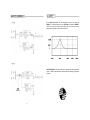
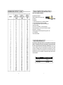
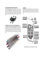
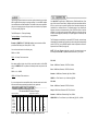
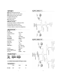
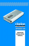
PCX 1250
PCX 1500
PrecisionPower 9235 South McKemy Street, Tempe, Arizona 85284 www.precisionpower.com
8900-4006
NO SOUND
Is the LED lit?
YES
NO
Check Power and Remote turn-on
wire for voltage. Make sure Ground
wire is secure.
STILL NO SOUND
See your Authorized PrecisionPower Dealer or call 1-800-62POWER.
SOUND IN ONE CHANNEL ONLY
NEW! Advanced Instrumentation Input Stage.
NEW! 12dB/Octave; HP/LP/FULL; 30-4kHz Crossover.
NEW! Independent Line Output Crossover 30-4kHz.
PWM Power Supply.
Triple Darlington Output Stage.
AP-IV Protection Circuitry.
QBASS™ Bass Boost.
High Voltage Input Capability with -12dB Attenuation Switch.
Gold Plated RCA Input and Output Connectors.
PowerLock™ Speaker and Power Wire Connectors.
3-Yr Warranty; installed by an Authorized PrecisionPower Dealer.
Reverse left and right speakers by unplugging the speaker connector, turning it
over and plugging it back in.
SOUND IS NOW IN
OPPOSITE CHANNEL
Reverse RCAinputs
SAME CHANNEL
Problem is in the speaker or
speaker wire of the silent channel
SOUND IS NOW IN
OPPOSITE CHANNEL
Reverse RCAs at head unit
SAME CHANNEL
Problem is in the Amplifier. See your
local Authorized PrecisionPower Dealer
or call 1-800-62POWER.
SOUND IS NOW IN
OPPOSITE CHANNEL
Problem is in the head unit
or before the amplifier
SAME CHANNEL
Problem is in the RCAcables
PCX 1250
Power Bandwidth
Total Harmonic Distortion
S/N Ratio
Input Topology
Input Sensitivity
Input Impedance
Load Impedance (mono)
Supply Voltage
Damping Factor
Slew Rate
QBASS ™
Crossovers
Crossover Frequency
Subsonic Crossover Frequency
Idle Current:
10 Hz - 50 kHz
< 0.02 %
> 110dB
Instrumentation
150mv - 12 Volts RMS
10k Ohms
2 - 8 Ohms
11 - 15 Volts
> 500
> 50 V/µS
Up To +12dB Boost
@ 40Hz
12dB/Octave
30-4kHz
5-80Hz
PCX 1250 1 Amp
MODEL
4ohm MONO
2ohm MONO
PCX 1250
1 X 250
1X 500
* ALL POWER RATINGS SHOWN ARE TESTED @ 12V; 20-20kHz
PCX 1250
20
Length
Height
Width
17.00”
2.375”
10”
1
On the PCX 1250 amplifier, we offer tremendous control of your bass with
QBASS™. On the front end panel of your PCX 1250 you will find the QBASS™
level control. Adjust the level control clockwise for up to 12 dB of boost at a
factory preset frequency of 40Hz with a Q-factor of 2
CAUTION: QBASS ™ should only be used in systems with a strong subwoofer
section. +12dB is a large amount of bass boost and may damage your speakers
if abused.
18
3
NOTE: TOOLS ARE NOT SUPPLIED
Small flat blade screwdriver
Phillips screwdriver (#2 or medium sized)
Wire cutters
Wire strippers
4 - #6 round head screws, and 1 - #8 sheet metal screw
(or nut, bolt, flat washer star washer) [see detail]
2 - Ring connectors (large enough to accommodate your
method of grounding)
In-line fuse or circuit breaker - see fuse chart below
Power and ground wire - see Power Wire Calculator on page 4
Speaker wire - 12-16 gauge
Grommets (sized to work with the power wire you plan to use
in your installation)
Tube of silicone sealant
You will need to install an in-line fuse or circuit breaker in the power wire
within 18" of the battery. This fuse or circuit breaker is to protect your vehicle
from fire in case the power wire shorts to the vehicle body. If you are only
using one amplifier, use the fuse rating indicated in this chart. If you are using
more than one amplifier, add up the fuse ratings for all the amplifiers. This sum is
the rating for your main fuse or circuit breaker. You may also want to add a power
distribution block near your amplifiers to distribute large gauge power cable to
multiple amplifiers.
16
Amplifier
Maximum Fuse Rating
PCX 1250
PCX 1500
60 Amp
100 Amp
5
The New! PCX™ amplifiers mass has been increased by 2 lbs. per linear foot
over last year’s P O W E RC L A S S ™ amplifiers, resulting in far superior heat
dissipation. The unique heatsink on your PCX™ amplifier has been designed with
fins on the inside of the aluminum extrusion. This allows for the transfer of heat
from the circuitry to the heatsink fins and out through the vents in the endplates.
Be sure you have ample space around the amplifier for cooling; at least 2" on all
sides.
Before beginning, disconnect the negative (-) terminal of the battery prior to
working on the positive (+) terminal to prevent a short to ground. This is important,
unless you want to spend the rest of your life with a nickname like "Sparky," or
"Smokey." Reconnect the negative terminal only after all connections have been
made.
To manage the additional heat associated with higher output capability, a thermally
controlled fan has been designed into the PCX 1500. When the heatsink temperature reaches a pre-determined value, the fan is activated and cool air is
drawn in through the lower intake vents on the endplate. This cool air flows below
the circuit board, through the fan and across the internal fins, cooling the
heatsink. The warm air is then forced out through the upper endplate exhaust
vents.
Warning! A Main Fuse must be installed within 18" of battery!
14
7
When using 16 gauge or larger, run the speaker wires from the amplifier location
through the vehicle to the speakers. Observe the same precautions for routing
these wires that you followed for running the power and remote turn-on wires. Cut
o ff excess and, using wire strippers, strip 1/4 inch of insulation. Locate the
speaker/remote turn-on PowerLock connector. Loosen the outer screws on the
underside of the connector. Insert the speaker leads into the end. Check to be
sure you've maintained proper polarity before securing each wire, and plug the
PowerLock into the amplifier.
Once you have run both the power and ground wires, it's time to connect the
cables to the amplifier. Cut off excess wire and, using wire strippers, strip the ends
of the power and ground cables approximately 1/4 inch. Locate the PowerLock
power and ground connector (supplied). With a small flat bladed screw driver,
loosen the screws before attempting to insert the cables. Insert the wires into the
appropriate hole, and tighten the screws. Once the wires are secure, the
PowerLock™ may be plugged into the amplifier. The Power/Ground
PowerLock™ will accommodate 4 gauge wire for the PCX 1500 .
Power/Ground PowerLock™
12
9
PCX 1250
PCX 1500
6
7
8
9
10
11
12
1
2
3
4
6
7
8
9
10
11
12
1
3
5
2
1. Cooling Plenums: Maintain a minimum 2” clearance around cooling plenums for proper amplifier
cooling.
2. HP/LP/FULL Switch: Select the desired crossover setting, HP/LP/FULLfor the speaker output
signal of the front channel.
3. Freq. Control: Move this detented control in a clockwise rotation to adjust the front crossover frequency from 30Hz to 4kHz.
4. Subsonic Filter Freq. Control: Move this detented control in a clockwise rotation to adjust the
subsonic crossover frequency from 5Hz to 80Hz.
5. RCAInputs: Connect the RCAcables from the head-unit, video unit, or line driver to these RCA
connectors.
6. Gain Control: Use this control to match the output level of the source unit to the input of the amplifier.
7. -12dB: For use with high level inputs (4V up to 12V). Push this switch in to attenuate the input by
12dB.
8. QBASS™ 0 to +12dB
9. Output Crossover HP/LP/FULLSwitch: Select the desired crossover setting, HP/LP/FULLfor
the output signal of the RCAoutput.
10. Output Crossover Freq. Control: Move this detented control in a clockwise rotation to adjust
the front crossover frequency from 30Hz to 4kHz.
11. RCAOutputs: RCAoutputs provide HP/LP/Full; 30-4KHz to another amplifier.
12. Speaker Output Connections: Plug the Speaker PowerLock™ connector in here.
2
1
3
1. Thermal Management Intake/Exhaust Plenums
2. Power / Ground PowerLock: After you have securely connected your power and ground wires,
plug in the Power/Ground PowerLock connector here.
3. Power indicator: A green light indicates that the amplifier is on.
10
4
5
1. Cooling Plenums: Maintain a minimum 2” clearance around cooling plenums for proper amplifier
cooling.
2. Subsonic Filter Freq. Control: Move this detented control in a clockwise rotation to adjust the
front crossover frequency from 5Hz to 80Hz.
3. HP/LP/FULL Switch: Select the desired crossover setting, HP/LP/FULL for the speaker output
signal of the front channel.
4. Freq. Control: Move this detented control in a clockwise rotation to adjust the front crossover frequency from 30Hz to 4kHz. (See Crossover frequency chart pg. 16)
5. RCAInputs: Connect the RCAcables from the head-unit, video unit, or line driver to these RCA
connectors.
6. QBASS 1 & QBASS 2 Freq.: Use these switches, QBASS 1 & QBASS 2 to program the QBASS
PLUS™ circuit frequency.
6. -12dB Input Attenuation: Push this switch ‘IN’ for high voltage input (4V-12V) capability. This button
pushed ‘IN’ must be used for speaker level input on common ground head-units or for high voltage line drivers.
8. Freq. Control: Move this detented control in a clockwise rotation to adjust the front crossover frequency
from 30Hz to 4kHz.
9. Output Crossover Control: HP/LP/FULL, Move this detented control in a clockwise rotation to
adjust the front crossover frequency from 30Hz to 4kHz. (See Crossover frequency chart pg. 16)
10. Gain Control: Use this control to match the output level of the source-unit to the input of the amplifier
11. RCAOutputs: Left and right RCAoutputs provide HP/LP/Full;
30-4KHz to another amplifier.
12. Speaker Output Connections: Plug the Speaker PowerLock™ connector in here.
1
2
3
4
5
1. Forced Air Thermal Management Intake/Exhaust Plenums
2. QBASS PLUS™: level control up to 18dB.
3. QBASS REMOTE™ plug in: Plug in the data cable from the optional QBASS REMOTE™ dash
mount level control here. (This will bypass the amplifier’s on board QBASS™ control)
4. Power / Ground PowerLock: After you have securely connected your power and ground wires,
plug in the Power/Ground PowerLock connector here.
5. Power indicator: A green light indicates that the amplifier is on.
11
Locate an area near the amplifier(s) that is metal and clean an area about the size
of a quarter to bare metal. Inspect the area around and underneath to be sure you
won't drill into wires, brake or fuel lines, etc. Drill a pilot hole in the middle of this
area. Terminate the ground wire with a ring connector and attach it to the bare
metal using a #8 sheet metal screw and washer or preferably, a bolt, nut and a
star washer (not supplied). We suggest crimping and soldering this connection.
After the connection is complete, coat the area (on both sides) with silicone or
some similar material to prevent rust from developing on the bare metal. If your
grand total current draw is over 50 amps (or total output power is over 300 watts),
you should run a separate ground wire beside your power wire from the battery
to the amplifier(s). Keep the ground and power wires as close together as possible, and use the same gauge wire for both. This will ensure that you have a good
ground path, and may eliminate such potential problems as engine noise and
overheated amplifiers.
If your grand total current draw is over 100 amps (or total output power is over
600 watts), you are probably exceeding the capability of your charging system.
Dimming lights and fluctuating voltage are solid indicators that you need to
upgrade your alternator, battery, or both. Keep in mind that your amplifiers simply
convert electrical energy to acoustical energy, and any electrical deficiency will
compromise the performance of your sound system. For more information about
charging system upgrades, see your local authorized PrecisionPower Dealer or
call PrecisionPower Technical Support at 1-800-62POWER x 229.
8
There are two sets of RCA jacks on the front end of your amplifier. The RCA
cables from your source unit go in the set labeled INPUTS. If your source unit doesn't
have RCA outputs don't worry. Simply add a set of RCA plugs (available at your
dealer) to your front or rear set of speaker leads (see drawing below), plug them
into the input jacks, and push to the IN position -12dB input attenuation switch.
The Advanced Instrumentation Input has trickled down from the $15,000
PrecisionPower 2500F1. This circuit completely isolates the chassis ground from
the audio circuit of the amplifier and reduces noise radiated into your signal cables
by up to 40dB. This is equivalent to a noise reduction of approximately one hundred
times what the noise level would be without this circuitry. It provides all the benefits
of a true 'balanced' line without the need of any special cables (see diagram
below). This type of input works with any conventional RCAcable.
13
The following is a basic formula to be used as a guide to determine current draw.
A50% amplifier efficiency rating is used as an average. Your new PCX™ amplifier
is more efficient than most other amplifiers. This formula is to be used as a guideline.
Using wire of a larger gauge can only improve the current transfer of your system.
Do not use smaller gauge wire.
Total RMS output x 2 = Total Input Wattage
Total Input Wattage = Current Draw (in Amps)
Supply Voltage
Example: A POWERCLASS™ PCX 1500 amplifier has two channels at 200w
per channel RMS rating into 4 Ohms (500 x 1 = 500).
You would use the formula in the following way:
500W = 41.6 Amps Total current draw.
12V
PCX 1250
If the same amplifier is driven into a 2 Ohm mono load, double it's 4 Ohm RMS
rating. All POWERCLASS™ amplifiers will effectively double their power at this
load.
500W x 1 x 2 = 1000W
Rear - 12dB/Octave, Detented; HP/LP/Full; 30-4kHz;
QBASS - on Front Channel - up to 12db boost @ 40Hz.
If you are using more than one amplifier, add up the total current draw for all of
them and choose the appropriate gauge based on the grand total.
Total Current Draw
Length Of Wire To Be Run
7 to 10ft.
6
4
4
4
2
0
00
000
10 to 13ft.
4
4
2
2
2
0
000
0000
13 to 16ft.
4
2
2
2
0
00
000
0000
16 to 19ft.
4
2
2
0
0
00
000
0000
PCX 1500
Front - 12dB/Octave, Detented HP/LP/Full; 30-4kHz
Output - 12dB/Octave, Detented; HP/LP/Full; 30-4kHz
Recommended Minimum Gauge
4 to 7ft.
8
6
6
4
2
0
00
000
Front - 12dB/Octave, Detented; HP/LP/Full; 30-4kHz
Subsonic - 12dB/Octave, Detented; High Pass; 5-80Hz
1000W = 83.3 Amps Total current draw.
12V
Up to 4ft.
8
6
6
4
2
0
00
000
The RCAoutputs are controlled by a separate HP/LP/Full switch, and are always
independent of the speaker output crossover. As well as being able to independently
select HP/LP/Full, your new P C X ™ amplifier allows independent selection of
frequencies from 30-4kHz (See page 19).
NOTE: The System Diagrams beginning on page 18 show several ways to use
the virtually unlimited PCX™ amplifiers internal crossovers in your system.
500W x 1 = 500W
(in amps)
50-65
65-85
85-105
105-125
125-150
150-200
200-250
300-up
Your New! PCX™ amplifier has a TC-X Crossover (Total Control X-over©) (See
page 19 for crossover Detent Chart). 12dB per octave phase correlated crossover
built in to provide superior system flexibility without the added expense and
installation of an outboard crossover. The speaker outputs of your amplifier are
high-pass, low-pass, or all-pass according to the HP/LP/Full switch on the front
endplate. You would choose low pass (switch middle) to use this amp for subwoofers, choose high pass (switch left), or full (switch right) to use this amp for full
range speakers.
Subsonic - 12dB/Octave Detented; High Pass; 5-80Hz
19 to 22ft.
4
2
2
0
0
00
000
0000
22 to 28ft.
2
0
0
0
00
000
0000
00000
NOTE: The ground wire should be the same gauge as the power wire.
QBASS PLUS - on Front Channel - up to 18db boost @ 30, 36, 44, 60Hz.
15
On the PCX 1500 amplifier, we've taken bass control to a higher level with
QBASS PLUS™. The two QBASS™ switches (labeled 1 and 2) on the front end
of the amplifier allow you to select one of four frequency centers 30Hz, 36Hz,
44Hz and 60Hz, with a Q-Factor of 2. On the rear end plate you will find the
QBASS™ level control and the plug-in for an optional QBASS REMOTE™ dash
mounted level control. Adjust the level control clockwise for up to +18dB of
boost at your selected frequency.
Short Circuit Protection engaged: The amplifier will turn off and try to come
back on immediately. The amplifier will cycle like this indefinitely, with "blips" of
sound each time. If this is the case, check your speakers and wiring for low
impedance and short circuits.
Thermal Protection engaged: The amplifier will turn off and several minutes
later will come back on. In this case, ensure that there is nothing blocking the
normal convective airflow of the amplifier. No obstruction should be within 2" of
the amplifier on all sides.
NOTE: Low battery voltage will cause the amplifier to run warmer and
possibly damage the amplifier.
Q BASS™ Settings
1
2
Freq.
IN
IN
30Hz
IN
OUT 36Hz
OUT
IN
44Hz
OUT OUT 60Hz
CAUTION: QBASS PLUS™ should only be used in systems with a strong subwoofer
section. +18dB is a tremendous amount of bass boost and may damage your
speakers if abused.
Optional QBASS REMOTE™: This boost control can be mounted in the dash and
will supersede the boost control on the endplate.
Both excessive temperature and low impedance (or short circuit) conditions will
activate the amplifier's AM-V protection circuitry, which turns down the amplifier's
output. When the amplifier cools down, or the impedance is corrected, the AM-V
will restore full power. If your amp is turning down, check your speakers and wiring
for low impedance and short circuits. Also, ensure that there is nothing blocking
the normal convective airflow of the amplifier. No obstruction should be within 2"
of the amplifier on all sides.
NOTE: Low battery voltage will cause the amplifier to run warmer and
possibly damage the amplifier.
PrecisionPowerPCX™ amplifiers no longer need an optional QPORT™ to connect
multiple QBASS PLUS™ equipped amplifiers while using one QBASS
REMOTE™. The new QBASS PLUS™ circuitry in the PCX™ amplifiers is now
positioned before the crossover circuit. In doing this, PrecisionPower engineers
have allowed you to daisy chain your RCAoutput to the next amplifier input, causing
the first amplifier’s Q BASS Remote™ to become the master control amplifier. See
your Authorized PrecisionPower Dealer for more information! (See diagram pg.18)
4
17
NEW! Advanced Instrumentation Input Stage.
NEW! 12dB/Octave; HP/LP/FULL; 30-4kHz Crossover.
NEW! Independent Line Output Crossover 30-4kHz.
Fully Regulated PWM Power Supply.
Triple Darlington Output Stage.
AM-V Protection Circuitry.
Forced Air Thermal Management.
QBASS Plus™ Bass Boost.
High Voltage Input Capability with -12dB Attenuation Switch.
Gold Plated RCAInput and Output Connectors.
PowerLock™ Speaker and Power Wire Connectors.
3-Yr Warranty; installed by an Authorized PrecisionPower Dealer.
PCX 1500
Power Bandwidth
Total Harmonic Distortion
S/N Ratio
Input Topology
Input Sensitivity
Input Impedance
Load Impedance (mono)
Supply Voltage
Damping Factor
Slew Rate
QBASS PLUS™
Crossovers
Crossover Frequency
Subsonic Crossover Frequency
Idle Current:
MODEL
4ohm MONO
PCX 1500
1 X 500
20 Hz - 20 kHz
< 0.02 %
> 110dB
Instrumentation
150mv - 12 Volts RMS
10k Ohms
2 - 8 Ohms
11 - 15 Volts
> 500
> 50 V/µS
Up To +18dB Boost
@ 30, 36, 44, or 60Hz
12dB/Octave
30-4kHz
5-80Hz
PCX 1500
2 Amps
2ohm MONO
1 X 1000
* ALL POWER RATINGS SHOWN ARE TESTED @ 12V; 20-20kHz
PCX 1500
Length
Height
Width
25.00”
2.375”
10”
2
19
Three-Year Limited U.S.A Warranty
And thank you for choosing PrecisionPower audio equipment. At PrecisionPower
we proudly design, engineer and manufacture audio products at our production
facilities. Our award winning engineering team utilizes innovative technology to
consistently deliver Absolutely State of the Art TM performance, sound quality,
reliability, and value. This PrecisionPower product reflects our commitment to
offer you unparalleled versatility and quality for years of dependable service and
listening enjoyment.
Do not attempt to service PrecisionPower products yourself. Performing
exploratory surgery on your audio equipment yourself will void the warranty. Many
parts of your PrecisionPower product are custom built to our specifications. Our
factory parts are not made available to anyone else nor are they for sale. Our goal
is to make sure that your PrecisionPower product will always sound as good as
the day it was purchased. Contact your Authorized PrecisionPower Dealer about
obtaining any warranty service through PrecisionPower. (See Warranty inside
back cover)
The extended use of a high powered audio system may result in hearing loss or
damage. While PrecisionPower systems are capable of "Concert Level" volumes
with incredible accuracy, they are also designed for you to enjoy at more reasonable
levels all of the sonic subtleties created by musicians. Please try to observe all
local sound ordinances.
This warranty gives you specific legal rights, and you may also have other rights which vary from state
to state. PrecisionPower warrants its products to be free from defects in materials and workmanship
under normal use and service for a period of three (3) years from the date of original purchase when
the unit is installed by an Authorized Dealer. Non-Authorized Dealer installed products carry a one (1)
year parts and ninety (90) days labor limited warranty. The extent and conditions of Limited Warranty
are as follows:
1. Authorized Dealer Installed Products: PrecisionPower will either repair or replace at no charge, to
the original purchaser, any unit which PrecisionPower examination discloses to be defective and
under warranty, provided the defect occurs within three (3) years from the date of original purchase
when the unit is installed by an Authorized Dealer and the product is returned immediately to
PrecisionPower. This warranty is not transferable.
2. Non-Authorized Dealer Installed Products: PrecisionPower will either repair or replace at no charge,
to the original purchaser, any unit which PrecisionPower examination discloses to be defective and
under warranty, provided the defect occurs within ninety (90) days from the date of purchase and the
product is returned immediately to PrecisionPower. Warranty claims beyond ninety (90) days for NonAuthorized Dealer Installed Products will be for parts only and will extend for one (1) year from the
date of purchase. This warranty is not transferable.
3. Internet and mail order products purchased from non authorized PrecisionPower dealers are not
subject to factory warranty. PrecisionPower does not endorse or approve of internet and mail order
sales, but will repair products at current non warrantied part and labor rates.
4. The date of purchase and proof of Authorized Dealer Installation of a PrecisionPower product must
be established by an original sales receipt which must accompany the article being re-turned for warranty work.
5. This warranty shall NOTapply to any PrecisionPower product found to have the original factory serial
number removed or defaced. All products received (by PrecisionPower) for in warranty or out of war ranty repair, with their original serial numbers removed or defaced, will NOTbe repaired and will be
returned to sender, freight collect. Refer to original packaging for the serial number of your component
speakers.
6. The provisions of this warranty shall not apply to any PrecisionPower product used for a purpose
for which it is not designed, which has been repaired or altered in any way, or which has been connected, installed, or adjusted other than in accordance with the instructions furnished in
PrecisionPower owner’s manual. Nor shall this warranty apply to any part which has been subject to
misuse, neglect, or accident.
7. PrecisionPower does not authorize any other persons to assume any other liability in connection
with its products. THIS WARRANTY IS THE ONLY EXPRESS WARRANTY MADE BY
PrecisionPower APPLICABLE TO ITS PRODUCTS. ANY IMPLIED WARRANTY OR MERCHANTABILITY OR FITNESS FOR A PARTICULAR PURPOSE APPLICABLE TO PrecisionPower
PRODUCTS IS LIMITED IN DURATION TO THE DURATION OF THIS LIMITED WARRANTY.
PrecisionPower SHALL NOT BE LIABLE FOR THE INCIDENTAL, CONSEQUENTIAL, OR COMMERCIAL DAMAGES RESULTING FROM THE BREACH OF THIS WRITTEN WARRANTY. Some
states or provinces do not allow the exclusion or limitation of incidental or consequential damages or
limitations on how long an implied warranty lasts;so the above limitations or exclusions may not apply
to you.
8. Your product will be serviced on an in-warranty basis within the warranty period for the correction
of warranted defects. If improper operation of your PrecisionPower product should occur, contact your
Authorized Dealer for assistance with the return and factory repair of your PrecisionPower product. If
an Authorized Dealer is not available, return the unit including your name, telephone number, return
address, a copy of your sales receipt, and a description of the problem to:
PrecisionPower
Service Department
9235 S. McKemy Street
Tempe, AZ 85284
TO RETURN PrecisionPower PRODUCTS OUTOF WARRANTY: Return the unit, postage prepaid,
in the original protective carton. Please include a description of the problem and, if desired, a request
for an estimate of repair costs. Unless a request for an estimate is included, the unit will be repaired
as necessary. Please contact PrecisionPower Customer Service at 1-800-62-POWER for questions
concerning out of warranty repair charges. Repaired unit will be returned with an itemized statement,
C.O.D.
21