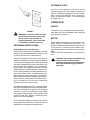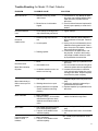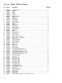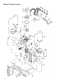
1
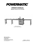
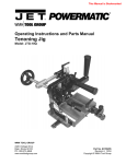
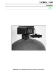
DUST COLLECTOR
Model 75
Instruction Manual & Parts List
M-0460200
(800) 248-0144
www.powermatic.com
This manual has been prepared for the owner and operators of a Powermatic Model 75 Dust
Collector. Its purpose, aside from machine operation, is to promote safety through the use of
accepted correct operating and maintenance procedures. Completely read the safety and maintenance instructions before operating or servicing the machine. To obtain maximum life and
efficiency from your dust collector and to aid in using the machine safely, read this manual thoroughly and follow all instructions carefully.
Warranty & Service
The JET Group warrants every product it sells. If one of our tools needs service or repair, one of our Authorized
Repair Stations located throughout the United States can give you quick service.
In most cases, any one of these JET Group Repair Stations can authorize warranty repair, assist you in obtaining parts, or perform routine maintenance and major repair on your JET, Performax or Powermatic tools.
For the name of an Authorized Repair Station in your area, please call 1-800-274-6848.
More Information
Remember, the JET Group is consistently adding new products to the line. For complete, up-to-date product
information, check with your local JET Group distributor.
JET Group Warranty
The JET Group (including Performax and Powermatic brands) makes every effort to assure that its products
meet high quality and durability standards and warrants to the original retail consumer/purchaser of our products that each product be free from defects in materials and workmanship as follow: 1 YEAR LIMITED WARRANTY ON ALL PRODUCTS UNLESS SPECIFIED OTHERWISE. This Warranty does not apply to defects
due directly or indirectly to misuse, abuse, negligence or accidents, normal wear-and-tear, repair or alterations
outside our facilities, or to a lack of maintenance.
THE JET GROUP LIMITS ALL IMPLIED WARRANTIES TO THE PERIOD SPECIFIED ABOVE, FROM THE
DATE THE PRODUCT WAS PURCHASED AT RETAIL. EXCEPT AS STATED HEREIN, ANY IMPLIED WARRANTIES OR MERCHANTIBILITY AND FITNESS ARE EXCLUDED. SOME STATES DO NOT
ALLOW LIMITATIONS ON HOW LONG THE IMPLIED WARRANTY LASTS, SO THE ABOVE LIMITATION MAY
NOT APPLY TO YOU. THE JET GROUP SHALL IN NO EVENT BE LIABLE FOR DEATH, INJURIES TO
PERSONS OR PROPERTY, OR FOR INCIDENTAL, CONTINGENT, SPECIAL, OR CONSEQUENTIAL DAMAGES ARISING FROM THE USE OF OUR PRODUCTS. SOME STATES DO NOT ALLOW THE EXCLUSION
OR LIMITATION OF INCIDENTAL OR CONSEQUENTIAL DAMAGES, SO THE ABOVE LIMITATION OR EXCLUSION MAY NOT APPLY TO YOU.
To take advantage of this warranty, the product or part must be returned for examination, postage prepaid, to an
Authorized Repair Station designated by our office. Proof of purchase date and an explanation of the complaint
must accompany the merchandise. If our inspection discloses a defect, we will either repair or replace the
product, or refund the purchase price if we cannot readily and quickly provide a repair or replacement, if you are
willing to accept a refund. We will return repaired product or replacement at JET's expense, but if it is determined there is no defect, or that the defect resulted from causes not within the scope of JET's warranty, then
the user must bear the cost of storing and returning the product. This warranty gives you specific legal rights;
you may also have other rights which vary from state to state.
The JET Group sells through distributors only. Members of the JET Group reserve the right to effect at any
time, without prior notice, those alterations to parts, fittings, and accessory equipment which they may deem
necessary for any reason whatsoever.
TABLE OF CONTENTS
Safety Rules ...................................................................................................................................... 4-5
Safety Decals ....................................................................................................................................... 6
Specifications ........................................................................................................................................ 7
Receiving .............................................................................................................................................. 8
Installation and Assembly ..................................................................................................................... 8
Accessories Attachment: Dust Bags & Hose .................................................................................. 8
Electrical Connection ...................................................................................................................... 8
Grounding Instructions .................................................................................................................... 9
Extension Cord ............................................................................................................................... 9
Operation .............................................................................................................................................. 9
Switch ............................................................................................................................................ 9
Motor .............................................................................................................................................. 9
Maintenance ....................................................................................................................................... 10
Dust Bags .................................................................................................................................... 10
Trouble-shooting .................................................................................................................................. 11
Parts List & Exploded View ............................................................................................................ 12-14
!
SAFETY RULES
Read the Manual. Always read the owner's manual carefully before attempting to use the machine. Know the
limitations and hazards associated with its use.
Eyes. Always wear approved safety goggles, glasses, or a face shield when operating this machine.
Dress Code. Do not wear loose clothing, neckties, jewelry, or gloves that can get caught in moving parts. Confine
long hair. Keep sleeves above the elbow.
Electrical Grounding. Your machine must be electrically grounded. If a cord and plug are used, make certain the
grounding lug connects to a suitable ground. Follow the grounding procedure indicated by the National Electric
Code.
Guards. Keep machine guards in place at all times when machine is in use. If removed for maintenance purposes, use extreme caution and replace the guards immediately.
Do not overreach. Maintain a balanced stance at all times so that you do not fall or lean against blades or other
moving parts.
Power off. Make sure the machine is either unplugged or electrically disconnected and locked out when performing maintenance or service work.
Housekeeping. Before turning on machine, remove all extra equipment such as keys, wrenches, scrap, stock,
and cleaning rags from the machine. Keep the area around machine clean and free of scrap material and sawdust
to mimimize the danger of slipping.
Power on. On machines equipped with a manual starter make sure the starter is in "OFF" position before
connecting power to machine.
Use the right tool. Don't force a tool or attachment to do a job which it was not designed for.
Check damaged parts. Check for alignment of moving parts, binding of moving parts, breakage of parts, mounting, and any other condition that may affect the machine's operation. A guard or other part that is damaged should
be properly repaired or replaced.
Turn power off. Never leave machine running unattended. Do not leave machine until it comes to a complete
stop.
No horseplay. Give your work your undivided attention. Looking around, carrying on a conversation, and "horseplay" are careless acts that can result in serious injury.
Use recommended accessories; improper accessories may be hazardous.
Collect wood materials only. Metal shavings and dust can set wood dust on fire.
Do not expose the dust collector to moisture or wet surfaces. Use only indoors and on a dry surface to avoid the
risk of electrical shock.
Do not use the dust collector around flammable products. Sparks may ignite the vapors.
Do not operate the dust collector without the hose connected to the suction chute. Hazardous moving parts are
inside and could cause serious injury.
Drugs, alcohol, medication. Do not operate tool while under the influence of drugs, alcohol, or any medication.
4
Health Hazards. Some dust created by power sanding, sawing, grinding, drilling and other construction
activities contains chemicals known to cause cancer, birth defects or other reproductive harm. Some examples of these chemicals are:
* Lead from lead-based paint.
* Crystalline silica from bricks and cement and other masonry products.
* Arsenic and chromium from chemically-treated lumber.
Your risk from these exposures varies, depending on how often you do this type of work. To reduce your
exposure to these chemicals, work in a well-ventilated area, and work with approved safety equipment, such
as those dust masks that are specifically designed to filter out microscopic particles.
Familiarize yourself with the following safety notices used in this manual:
!
!
CAUTION: (This means that if precautions are not heeded, it may result in minor or moderate injury
and/or possible machine damage)
WARNING: (This means that if precautions are not heeded, it could result in serious injury or
possibly even death).
5
! SAFETY
Familiarize yourself with the location of these safety decals on your dust collector.
6
SPECIFICATIONS: Model 66, 10" Table Saw
Motor .................................................................................................. 3 HP, 1 Ph, 230V
.................................................................. 3 HP, 3 Ph, 230/460V (prewired 230V)
CFM ........................................................................................................................ 1900
Capacity ........................................................................................................... 10 cu. ft.
Upper dust bag ....................................................................................................... cloth
Lower dust bag ........................................................................................... clear plastic
Switch ......................................................................................... industrial push button
Height ........................................................................................................................ 90"
Inlet sizes ............................................................................. one-8", one-6", or three-4"
Casters ........................................................................................................... four swivel
Weight (gross) .............................................................................................. 154.32 lbs.
NOTE: The above specifications were current at the time this manual was published, but because of our policy
of continuous improvement, Powermatic reserves the right to change specifications without notice and without
incurring obligations.
7
RECEIVING
Remove all contents from the shipping carton and
check each item against the packing list. Report any
missing or damaged parts immediately to your shipping agent and distributor. Read the instruction manual
thoroughly for assembly, alignment, maintenance and
safety instructions.
Box contents:
1 impeller housing with motor
2 housings
1 hose adapter
4 retainer straps
1 8"-6" adapter
1 support plate
4 clear (lower) bags
2 extension plates
2 cloth (upper) bags
4 support legs
2 upper hangers
2 support brackets
2 lower hangers
2 rubber gaskets
1 hardware bag containing: 4 casters, 2 hanger brackets, nuts, screws, washers.
INSTALLATION AND ASSEMBLY
Use the exploded view on page 14 to assist with the
following instructions:
1. Turn the base (18) on edge and screw the four
casters (21) into the threaded holes. Secure with nuts
(40) and lock washers (45).
2. Attach the two end extension plates (19) with
the hex head screws (32) and nuts (38) with lock washer
(46) and flat washer (43).
3. Mount the support plate (20) to both sides of base
using hex head screws (32) with flat washers (43),
lock washers (46), and nuts (38).
4. Mount the two support brackets (15) to the base
and support plate using the hex head screws (32) and
flat washers (43). NOTE: Be careful that you do not
strip the screws.
5. If shipped unassembled, mount the motor (22),
shaft key (25), and gasket (26) to the underside of the
impeller housing (1), and lock down on the topside
with nuts (39), lock washers (44), and flat washers
(42).
6. With the aid of an assistant, mount the impeller
housing (with attached motor) to the support brackets
(15) aligning the holes of the four housing bolts and
securing with nuts (38), lock washers (46) and flat
washers (43).
8
7. Screw the impeller (3) on to the threaded motor
shaft and be sure to install the shaft key (25) at the
same time. Tighten down with nut (37) and washer
(41).
8. Install the housing gasket (4) and inlet cover (5)
to the housing using the round head sheet metal
screws (31).
9. Attach both side housing units (2) with rubber
gaskets (30) to the impeller housing using the hex
head screws (32), washers (43), and nuts (38).
10. Attach the four leg supports (14) first to the base
(18) with hex head screws (32), washers (43), lock
washers (46) and nuts (38). Next, attach the top section of the hanger brackets to the side housing units
with hex head screws (32), washers (43), lock washers (46) and nuts (38).
NOTE: As shown in the exploded view, one bracket
on either side is mounted to the side housing with a
hanger bracket (11). Be sure to install hanger bracket
during assembly at this time.
ACCESSORIES ATTACHMENT
Dust Bags & Hose
1. Screw upper hanger into lower hanger (9 & 10)
and secure with large nut (38). Attach this assembly
to the hanger bracket (11).
2. Install the lower (17) and upper (8) dust bags with
the straps provided making sure they are securely fastened with no air leaks.
!
CAUTION: Retainer straps are rolled up
under tension. Hold strap with hand
and allow it to unroll gradually.
3. Choose the hose adapter (7 or 53) according to
your particular requirements and attach the accessories as shown.
ELECTRICAL CONNECTION
The dust collector is equipped with a 3 HP, single phase,
230 volt or three phase, 230/460 volt motor. The unit
is factory wired for 230 volts and equipped with a 20
amp cord and plug set. The 230 volt plug requires a
receptacle as illustrated in Figure 1. The three phase
motor may be reconnected for 460 volts by changing
the connections as illustrated in the diagram motor
wiring box. The three phase power cord is not equipped
with a plug.
EXTENSION CORD
Use only a 3-wire extension cord with a 3-prong
grounding plug and a 3-pole receptacle as shown in
Figure 1. Replace a damaged or worn cord immediately. The use of an extension cord, if required, results in a certain loss of power. The recommended
wire gage is no. 10.
OPERATION
SWITCH
FIGURE 1
!
WARNING: The dust collector must be
grounded to protect the operator from
electric shock. Not all outlets are
properly grounded. Have your outlets
checked by a qualified electrician.
GROUNDING INSTRUCTIONS
All grounded, cord connected tools:
In the event of a malfunction or breakdown, grounding
provides a path of least resistance for electric current
in order to reduce the risk of electric shock.
This tool is equipped with an electric cord having an
equipment-grounding conductor and a grounding plug.
The plug must be plugged into a matching outlet that
is properly installed and grounded in accordance with
all local codes and ordinances. Do not modify the
plug provided if it will not fit the outlet; have the proper
outlet installed by a qualified electrician. Improper connection of the equipment-grounding conductor can result in risk of electric shock. The conductor with insulation having an outer surface that is green with or
without yellow stripes is the equipment-grounding conductor. If repair or replacement of the electric cord or
plug is necessary, do not connect the equipment
grounding conductor to a live terminal.
The switch box is an industrial type switch with standard "start" and "stop" push buttons, and is attached
to the impeller housing unit.
MOTOR
Motors used in a woodworking environment are constantly exposed to sawdust and wood chips. The
operator should make frequent inspections of the motor and remove, or vacuum, any accumulation of foreign material in order to maintain normal motor ventilation.
Remove dust from the motor with a low pressure air
hose.
!
CAUTION: The operator should follow all
safety procedures regarding dust
particles and always wear safety goggles
and a filter mask during any cleaning
operation.
Check with a qualified electrician or service personnel
if the grounding instructions are not completely understood, or if in doubt as to whether the tool is properly
grounded. Use only 3-wire extension cords that have
3-prong grounding plugs and 3-pole receptacles that
accept the tools' plug. Repair or replace any damaged or worn cord immediately.
As the three phase 230/460 volt motor does not have
a plug, please carefully follow the rotation direction of
impeller when connecting to the power source.
9
MAINTENANCE
!
WARNING: Never perform maintenance
on this machine before turning switch to
"stop" and removing plug from power
source.
DUST BAGS
Each operator has his own particular application of
woodworking machinery. As such, a maintenance
schedule for the dust collector must be performed on
a regular and timely basis. To remove dust and chips:
1.
Disconnect machine from its power source.
2. Shake the upper dust bag and allow the fine dust
to settle down into the lower chip bag.
3. Release the clamp around upper bag, remove the
upper bag and deposit all remaining dust into a fireproof metal container.
4. Release clamp around lower chip bag, remove
the chip bag and deposit chips and dust into a fireproof metal container.
5. Reconnect both sets of dust bags making sure
the clamps firmly secure the bags to the upper and
lower chute extensions.
10
Trouble-Shooting for Model 75 Dust Collector
PROBLEM
POSSIBLE CAUSE
Motor will not run.
1. Defective cord, plug, switch,
and/or motor.
2. Blown fuse or circuit breaker
tripped.
Excessive sawdust
in air.
Excessive
impeller noise.
Motor fails to develop
full power.
Motor starts slowly or
fails to come up to full
speed.
1. Consult service. Any attempt to repair
this motor may create a hazard unless
repair is done by a qualified service
technician.
2. Check for blown fuses and replace with
fuse of proper capacity or re-set circuit
breaker.
1. Loose clamps; dust bag and/or
chip collection bag not secure.
1. Tighten clamps.
1. Picked up large chips and debris.
1. Stop the machine to allow material to
fall to the bottom of inlet pipe. Remove
debris.
2. Unplug unit prior to disassembly due to
hazardous moving parts inside. Use a
piece of wood to free impeller. Attach to
inlet guard before plugging in.
3. Consult service to repair loose or rubbing impeller. A repair to the housing
may create a hazard unless it is done
by a qualified service technician.
2. Loose impeller.
3. Rubbing impeller.
Excessive noise.
SOLUTION
1. Motor.
2. Overloaded circuit.
3. Undersize extension cord or extension cord too long.
1. Low voltage.
2. Windings burned out or open.
3. Starting switch will not operate.
(Switch contacts not working
properly.)
1. Have motor check by a qualified service
technician.
2. Do not overload circuit when using dust
collection system with other appliances.
3. Increase the wire sizes on extension
cord, reduce length of extension cord or
use larger wire sizes. Request a power
check from the power company.
1. Request voltage check from power company.
2. Have motor repaired or replaced by a
qualified service technician.
3. Replace capacitor by a qualified service
technician.
Motor overheats.
1. Motor overloaded.
2. Improper cooling. (Air circulation
restricted through motor due to
sawdust accumulation inside of
motor.
1 & 2. Clean out sawdust and provide normal air circulation through motor.
Motor stalls.
1. Low voltage does not permit motor to reach operating speed.
2. Fuses or circuit breakers lack
sufficient capacity.
1. Request voltage check from power company.
2. Install proper size fuses or circuit breakers.
Frequent opening of
fuses or circuit
breakers.
1. Motor overloaded.
2. Fuses or circuit breakers lack
sufficient capacity.
1 & 2. Install proper size fuses or circuit
breakers.
11
Parts List: Model 75 Dust Collector
No.
Part No.
Description
1
2
3
4
5
6
7
8
9
10
11
12
13
14
15
16
17
18
19
20
21
22
6286605
6286606
6286607
6286608
6286609
6286610
6286611
6286600
6286619
6286620
6286621
6286622
6286623
6286624
6286625
6286626
6286601
6286627
6286628
6286629
6286656
6286603
6286604
6286631
6286632
6286633
6286634
6286635
6286636
6286637
6286638
6286639
6286660
6286642
6286643
6286644
6286645
6286445
6286647
6286446
6286662
6286663
6286664
6286665
6286666
6286654
6286655
3330283
6286657
6286658
3312334
6286618
Impeller Housing .................................................................................................... 1
Housing ................................................................................................................. 2
Impeller ................................................................................................................. 1
Gasket .................................................................................................................. 1
Inlet Cover ............................................................................................................. 1
Adapter, 8" - (3)4" .................................................................................................. 1
Adapter Cap .......................................................................................................... 2
Upper Bag ............................................................................................................. 2
Upper Hanger ........................................................................................................ 2
Lower Hanger ........................................................................................................ 2
Hanger Bracket ..................................................................................................... 2
Handle ................................................................................................................... 4
Support Block ....................................................................................................... 4
Support Leg ........................................................................................................... 4
Support Bracket .................................................................................................... 2
Retainer Strap ....................................................................................................... 4
Lower Bag ............................................................................................................. 2
Base ..................................................................................................................... 1
Extension Plate ..................................................................................................... 2
Support Plate ........................................................................................................ 1
Pivoting Caster ...................................................................................................... 4
Motor, 3 HP, 1 Ph, 230V ........................................................................................ 1
Motor, 3 HP, 3 Ph, 230/460V ................................................................................. 1
Power Cord ........................................................................................................... 1
Power Cord Holder ................................................................................................ 1
Motor Shaft Key .................................................................................................... 1
Motor Gasket ........................................................................................................ 1
Control .................................................................................................................. 1
Control Box ........................................................................................................... 1
Strain Relief ........................................................................................................... 2
Rubber Gasket ...................................................................................................... 2
Round Head Screw, M6 x 1 x 12 ........................................................................... 8
Hex Head Screw, M8 x 1.25 x 20 ........................................................................ 48
Socket Head Screw, M8 x 1.25 x 12 ..................................................................... 8
Self Tapping Screw, M4 x 0.7 x 10 ......................................................................... 2
Round Head Screw, M5 x 0.8 x 12 ........................................................................ 3
Nut, 5/8 x 18 UNF ................................................................................................. 1
Nut, M8 x 1.25 .................................................................................................... 42
Nut, M10 x 1.5 ...................................................................................................... 4
Nut, 3/8 x 16 UNF ................................................................................................. 4
Flat Washer, M16 .................................................................................................. 1
Flat Washer, M10 .................................................................................................. 4
Flat Washer, M8 .................................................................................................. 76
Lock Washer, M8 ................................................................................................ 16
Lock Washer, M10 ............................................................................................... 8
Plate "Better by Design" ........................................................................................ 1
Motor Plate ........................................................................................................... 1
Safety Rules Decal ................................................................................................ 1
Caution Decal ........................................................................................................ 1
Warning Label ....................................................................................................... 1
Serial Plate ........................................................................................................... 1
Adapter Attachment Kit, 8" - 6" (Items 54 thru 59) ................................................. 1
23
24
25
26
27
28
29
30
31
32
34
35
36
37
38
39
40
41
42
43
44
46
47
48
49
50
51
52
53
12
Quantity
Parts List: Model 75 Dust Collector
No.
Part No.
Description
Quantity
54
55
56
57
58
59
60
61
6286612
6286615
6286614
6286613
6286616
6286617
6286630
M-0460200
Hose, 20' x 4" ........................................................................................................ 1
Clamp, 4" .............................................................................................................. 1
Adapter, 4" - 4 ....................................................................................................... 1
Stainless Clamp, 4" ............................................................................................... 2
Plastic Tube, 3'L x 4" ............................................................................................ 1
Vacuum Head ........................................................................................................ 1
Hardware ............................................................................................................... 1
Manual .................................................................................................................. 1
13
Model 75 Dust Collector
14
To order parts or reach our service department, please call our toll-free number between 8:00 a.m. and 4:30 p.m.
(CST), Monday through Friday. Having the Model Number and Serial Number of your machine available when you
call will allow us to serve you quickly and accurately. Locating the EDP number of the part(s) required from your
parts manual will also expedite your order.
Phone No.: (800) 248-0144
Fax No.
(800) 274-6840
If you are calling from Canada, please call 800-238-4746
E-mail: [email protected]
Website: www.powermatic.com
15
07/01
JET Equipment & Tools
427 Sanford Road
LaVergne, TN 37086
Phone: (800) 248-0144
Fax: (800) 274-6840
E-mail: [email protected]
Website: www.powermatic.com
C
POWERMATIC
ALL RIGHTS RESERVED