1
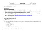
Data and Power on a Single Line
Power over LAN™ Midspans
PD-6006, PD-6012 & PD-6024
6/12/24-Port Models
IEEE 802.3af-compliant
User Guide
Notice
The information contained herein is believed to be accurate and reliable at the time of
printing. However, due to ongoing product improvements and revisions, PowerDsine cannot
accept responsibility for inadvertent errors, inaccuracies, subsequent changes or omissions
of printed material.
PowerDsine Ltd. reserves the right to make changes to products and to their specifications
as described in this document, at any time, without prior notice. This material may not be
photocopied or reproduced without permission.
Disclaimer
PowerDsine assumes no responsibility or liability arising from the use of Midspans, as
described herein, nor does it convey any license under its patent rights or the rights of
others. Applications that are described herein for any of theses products are for illustrative
purposes only. PowerDsine makes no representation or warranty that such applications will
be suitable for the specified use without further testing or modification.
The information in this guide refers to the 24-port Power over LAN Midspan
only. However this information and illustrations are also applicable for 6 and 12port AC, DC and AC/DC Power over LAN Midspans.
Note that the Midspan is designed for indoor use only.
© 2003 PowerDsine Ltd.
All rights reserved.
This document is subject to change without notice.
Original publication: 19 March 2003
Date Printed: Jun-18-2003
Acknowledgements
Power over LAN is a trademark of PowerDsine Ltd.
All other products or trademarks are property of their respective owners.
The product(s) described by this manual is (are) a licensed product of PowerDsine.
PD-6006/12/24
Contents
1
SAFETY INFORMATION .............................................................................
5
1.1 General Guidelines ................................................................................... 5
1.2 Power Cord............................................................................................. 6
2
ABOUT THE POWER OVER LAN MIDSPAN ........................................................
7
2.1 Power Management .................................................................................. 7
2.2 10/100BASE-TX Ports Definition ................................................................ 8
2.2.1 Data Input Ports ................................................................................ 8
2.2.2 Data & Power Output Ports .................................................................. 8
2.3 Indicators ............................................................................................... 8
2.3.1 Primary Power Indicators ..................................................................... 8
2.3.2 Port Indications ................................................................................. 9
2.4 Connectors ........................................................................................... 10
3
INSTALLING THE POWER OVER LAN MIDSPAN .................................................
11
3.1 Background Information ........................................................................... 11
3.2 Rack Mounting Brackets ........................................................................... 11
3.3 Connecting Ethernet Cables ...................................................................... 12
3.4 Connecting Power Cables......................................................................... 12
3.5 Powering up .......................................................................................... 12
3.6 Troubleshooting ..................................................................................... 12
3.6.1 Preliminary Steps ............................................................................ 12
3.6.2 Troubleshooting Guide ...................................................................... 13
4
WEB MANAGEMENT..............................................................................
Power over LAN Solutions
3
15
Cat. No.: 06-6800-056
PD-6006/12/24
Model Numbers Definition
PD-60xx/yyyy/M
where: xx represents the number of ports (6, 12 or 24)
yyyy establishes the type of input power used, such as:
AC (yy), or DC (yy), or both AC and DC (yyyy).
M if present, indicates that the Midspan includes the Web
Management feature (refer to Section 4).
The type of input power and the Web Management feature are customer- selected
Verifying Kit Contents
Unpack the kit and verify that the following items are uncluded:
• The Power over LAN Midspan
• Mounting brackets (for 19-inch racks)
• Screws for assembling mounting brackets
• Self-adhesive rubber feet
• User Guide
• Power cord.
Before proceeding, record the unit’s serial number below for future
reference. The serial number can be found on the information label at
the rear of the Power over LAN Midspan.
Serial Number
Electrical Compatibility Approvals
The PD-60xx/ACDC complies with the following standards:
• FCC Part 15, Class B, with FTP cabling; Class A with UTP cabling
• EN 55022 (CISPR 22), Class B with FTP cabling; Class A with UTP cabling
• EN 55024 (CISPR 24)
• Canadian ICES-003, Class B
Safety Standard Approvals
The PD-60xx/ACDC meets the following safety standards:
• UL/cUL per EN60950
• GS mark per EN60950
CE Marking
The CE marking on this product indicates that this product is in
compliance with 89/336/EEC (EMC Directive) and 73/23/EEC (Low
Voltage Directive).
Power over LAN Solutions
4
Cat. No.: 06-6800-056
PD-6006/12/24
1 Safety Information
1.1
General Guidelines
You must read the following safety information before carrying out any
installation, removal or any maintenance procedure on the Power over LAN
Midspan. Warnings contain directions that must be followed for personal and
product safety. Follow all directions carefully.
WARNINGS
a
•
Read the Installation Instructions in Section 3 before connecting the
Power over LAN Midspan to its power source.
•
The Midspan must use a grounded power cord, as defined in
paragraph 1.2.
•
This product relies on the building installation for short-circuit
(overcurrent) protection. Ensure that a fuse or circuit breaker no larger
than 15 A for 120 VAC, (U.S.) 10 A for 230 VAC (international) is
used.
•
Do not work on the system, connect or disconnect cables during
periods of lightning activity.
•
A voltage mismatch can cause equipment damage and may pose a
fire hazard. If the voltage indicated on the label is different from the
power outlet voltage, do not connect the Power over LAN Midspan to
this outlet.
•
For shelf-mounted equipment, be certain that the surface is stable and
strong enough to support the equipment. Do not stack more than four
the Power over LAN Midspans.
•
Ultimate disposal of this product should be handled according to all
local laws and regulations.
•
The Power over LAN Midspan "Data" and "Data + Power" ports are
shielded RJ-45 data sockets. They cannot be used as Plain Old
Telephone Service (POTS) telephone sockets. Only RJ-45 data
connectors may be connected to these sockets.
Power over LAN Solutions
5
Cat. No.: 06-6800-056
PD-6006/12/24
1.2
Power Cord
In the event that the power cord is replaced, the replacement must meet local
requirements.
The cord must be UL-approved or CSA certified.
U.S.A. and
The minimum specification for the flexible cord is:
Canada
• No. 18 AWG
• Type SV or SJ
• Three-conductor.
The cord set must have a rated current capacity of at least
10 A.
The attachment plug must be an earth-grounding type with a
NEMA 5-15P (15 A, 125 V) or NEMA 6-15P (15 A, 250 V)
configuration.
Denmark
The supply plug must comply with section 107-2-D1,
standard DK2-1a or DK2-5a.
Switzerland
The supply plug must comply with SEV/ASE 1011.
The appliance coupler (connecting to the Midspan and not to
the wall plug) must have a configuration for mating with an
EN60320/IEC320 appliance inlet.
The power socket outlet must be near the Midspan and be
easily accessible. You can only remove power from the unit by
disconnecting the power cord from the outlet.
This unit operates under SELV (Safety Extra Low Voltage)
conditions according to EN60950/IEC 950. The conditions are
only maintained if the equipment to which it is connected also
operates under SELV conditions.
France and Peru only: This unit cannot be powered from IT
supplies. If your supplies are of IT type, this unit must be
powered by 230 V (2P+T), via an isolation transformer with a
ratio of 1:1 and with the secondary connection point labeled
Neutral, connected directly to ground.
U.K. only: The Power over LAN Midspan is covered by
General Approval, NS/G/12345/J/100003, for indirect
connection to a public telecommunications system.
Power over LAN Solutions
6
Cat. No.: 06-6800-056
PD-6006/12/24
2 About the Power over LAN Midspan
PowerDsine’s family of Power over LAN Midspans, series 6000, injects power
over data-carrying Ethernet cabling. The PD-6006/6012/6024 Midspans,
support 6, 12 and 24 ports respectively in a 10/100BaseTx Ethernet network,
over TIA/EIA-568 Category 5/5e/6 cabling. DC operating power, for data
terminal units, is fed over unused pairs of the cabling (7/8 and 4/5).
The Power over LAN Midspan normally powers devices that are Power over
LAN enabled or are equipped to receive power over Ethernet. These devices
are called Powered Devices (PDs). Devices that are not equipped to receive
power over Ethernet may require an external power adapter in order to be
powered. Contact PowerDsine for such an adapter.
Power over LAN Midspan main features:
Remote power feeding of Ethernet terminals
Eliminates the need for AC outlets, local UPS and AC/DC
adapters
Universal range power input (100-240 VAC, 50/60 Hz and/or
46 to 57 VDC)
Power management
SNMP management (optional)
Independent overload and short-circuit protection per channel
Port status indications
Standard 19-inch rack mountable.
2.1
Power Management
When establishing a network, the total power required by PDs may exceed the
total power available from the Midspan. The built-in Power Management
feature will not allow the total power output to exceed the maximum power
available (refer to the Technical Specifications). When the total power
available is near maximum, attempts to connect an additional PD to a free port
will cause the corresponding LED of the port to blink orange, indicating an outof-power budget. This port will not deliver power. Power distribution is based
on “first come, first served” logic.
It is possible that connected and operating PDs will significantly increase or
suddenly raise their power requirements. If the power required exceeds the
power available, the Power over LAN Midspan will start to turn off ports,
starting from the last port down, until the total power is once again under the
maximum limit.
Power over LAN Solutions
7
Cat. No.: 06-6800-056
PD-6006/12/24
2.2
2.2.1
10/100BASE-TX Ports Definition
Data Input Ports
According to the model acquired, the Midspan has 6, 12 or 24 10BaseT/100Base-TX- data input ports, configured in a non-crossover manner
(straight-wired). These ports, shown in Figure 2-1 (bottom row of connectors),
are designed to carry Ethernet data only (Tx/Rx) over the standard 2-wire pairs
(pins 1/2 and 3/6).
Data & Power Output Ports
2.2.2
The Midspan has 6, 12 or 24 Data & Power ports also configured in noncrossover manner (straight-wired). These ports are designed to carry Ethernet
data over the standard 2-wire pairs (pins 1/2 and 3/6) and DC power over the
spare pairs (pins 4/5 and 7/8).
The Power over LAN Midspan is not a repeater. As such, the maximum distance from the
Ethernet switch is not to exceed 100 meters (328 ft). In accordance with the IEEE 802.3
standard, the Power over LAN Midspan is guaranteed to work up to this distance.
Figure 2-1: Power over LAN Midspan, Front View (PD-6024)
2.3
Indicators
A set of indicators provide the status of the Power over LAN Midspan and its
ports. Refer to Table 2-1 and Table 2-2 for status information during operation.
2.3.1
Primary Power Indicators
Depending on the configuration ordered, there may be two LEDs on the front
panel, marked by “AC” and “DC”, to provide the Power over LAN Midspan
power status. When either one of the indicators is illuminated in green, the
Power over LAN Midspan is receiving AC or DC power. The “AC” and “DC”
indicators are lit in orange to indicate an internal fault. Refer to Table 2-1 for
additional information.
Power over LAN Solutions
8
Cat. No.: 06-6800-056
PD-6006/12/24
2.3.2
Port Indications
One bi-color indicator (green and orange), per port, provides port status:
Green indicates that the terminal unit has been identified as
"Power over LAN Enabled" and is active and receiving power.
Orange indicates that the port is not supplying power and is
not active.
Refer to Table 2-2 for additional information.
Note
Due to the standard detection process performed on each PoL
port, power will not be supplied to an Ethernet device, that is not
PoL-enabled (indicated in orange or off). In this way, Ethernet
devices (not PoL-enabled) will not be affected by this connection.
Table 2-1: Power Status Indications
Indicator
Color
DC
AC and DC
Remarks
Internal power
supply unit is
unplugged or
faulty.
Internal power supply voltage
is too low. All ports are
disconnected.
Indicates AC
power input
active.
Internal power supply voltage
is within tolerance.
Green
blinking
Internal power
supply voltage is
out of tolerance.
All ports are disconnected.
Off
No DC input
power available.
DC input voltage is too low.
All ports are disconnected.
Indicates DC
power input
active.
DC input voltage is within
tolerance.
Green
blinking
DC Input voltage
is out of tolerance.
All ports are disconnected.
Orange
Internal problem
alarm.
Built in Test (BIT) failed.
Off
AC
Main Power
Status
Green
Green
Power over LAN Solutions
9
Cat. No.: 06-6800-056
PD-6006/12/24
Table 2-2: Port Status Indications
Port LED Color
Port Load Conditions
Port Voltage
Non-active load or
unplugged port.
Power to the port is disconnected.No
DC voltage present on spare pairs.
Green
Active load is plugged in
and complies with
normal load conditions.
Continuous nominal DC voltage is
present on the spare pairs.
Orange
Overload conditions; or
short; or forced external
voltage feed (constant
DC) into the port.
Power to the port is disconnected.
No DC voltage is present on the
spare pairs.
Green blinking
Transitional mode in
which load detection is in
process or discharged
capacitor in the PD.
Power to the port is disconnected.
No DC voltage is present on the
spare pairs.
Orange blinking
Total aggregated power
exceeds pre-defined
power budget.
Power to the port is disconnected.
No DC voltage is present on the
spare pairs.
Off
2.4
Connectors
The front panel of the Midspan includes a Console port (DB-9 connector). The
user may connect a terminal and perform software loading, via this connector,
using a standard null modem cable. The console port is set to 19,200-baud, 8
data bits, no parity and 1 stop bit. Pin connections for this connector are:
Pin 2 is Receive (RXD)
Pin 5 is Ground
Figure 2-2: Connecting to
the Midspan
Power over LAN Solutions
Ethernet
Switch
1
2
3
RJ-45 4
5
6
7
8
RJ-IN
Data
Data
Data
Data
1
2
3
4
5
6
7
8
RJ-OUT
Power Bus
Each data port is configured
as shown in Figure 2-2., as
data route-thru ports for all
data pins (pins 1, 2, 3 and
6).Be certain to use
Category 5 or higher cabling,
as shown in the figure.
Pin 3 is Transmit (TXD)
Pins 1 and 6 are shorted
1
2
3
4
5
6
7
8
PD
Data
Data
Data
DC +
DC +
Data
DC DC -
1
2
3
4
5
6
7
8
RJ-45
Midspan Channel
10
Cat. No.: 06-6800-056
PD-6006/12/24
3 Installing the Power over LAN Midspan
3.1
Background Information
As shown in Figure 3-1, the Midspan is connected in series to an Ethernet
switch/hub. The data outputs from the switch are connected to the Midspan.
The Midspan delivers power over spare twisted pairs (pins 7/8 and pins 4/5) of
the Category 5 cabling, without degrading the quality of data communications.
Most installations require the Midspan to be rack mounted, as described
hereafter.
Figure 3-1: Typical Installation
3.2
Rack Mounting Brackets
The Midspan comes with 19-in.
mounting brackets and screws. To
install the Midspan into a 19-in.
rack, first remove the selfadhesive rubber feet from the
bottom
surface.
Install
the
brackets using two screws per
side. Rack-mounting screws are
not provided.
Figure 3-2: Installing Mounting Brackets
Power over LAN Solutions
11
Cat. No.: 06-6800-056
PD-6006/12/24
3.3
Connecting Ethernet Cables
The ports on the front panel of the Midspan are configured as "route through"
ports for all eight conductors of the RJ-45 connectors. Use Category 5 cabling
in making connections.
1. Connect cables from the Ethernet Switch to the Data ports (bottom
row on Midspan).
2. Connect the cables from the IEEE 802.3af ready terminals (PDs) to
the corresponding Data & Power ports (top row on Midspan).
3.4
Connecting Power Cables
When using AC to power the Midspan, plug in the power cord supplied, at the
rear AC connector. If DC is to be used (as primary or back-up power), connect
the DC primary wiring to a Molex P/N 44441-2002 connector, with 2 Molex
terminals P/N 4330-75/0001. Pin 1 is the positive polarity of the DC connector,
at the rear of the chassis.
3.5
Powering up
The Power over LAN Midspan has no on/off switch. To apply or remove power
to the Midspan, insert or remove the power cable from the receptacle(AC
and/or DC) on the rear panel of the unit.
With power applied, the Midspan powers-up and the internal fan operates;
then, the device runs through its power-on self-test (POST), which takes less
than 10 seconds. During the POST, all ports are disabled and the indicators
illuminate in the following sequence:
1. Port indicators and power indicators (AC & DC) illuminate green.
2. Port indicators and the AC indicator illuminate orange.
3. Main (AC or DC) indicator remains lit green; port indicators are out.
Ports are now enabled for normal operation.
3.6
3.6.1
Troubleshooting
Preliminary Steps
If you encounter problems, check that:
Power is applied to the Midspan
A crossover-type Ethernet cable has not been used
The Ethernet cable from the network is connected to the Data port
The Ethernet cable to the PD is connected to the Data & Power port
Cable pairs are attached to corresponding ports.
Power over LAN Solutions
12
Cat. No.: 06-6800-056
PD-6006/12/24
3.6.2
Troubleshooting Guide
This paragraph provides a symptom and resolution sequence in order to assist
in the troubleshooting of minor operating problems. If the steps given do not
solve your problem, do not hesitate to call your local dealer for further
assistance. Refer to Table 3-1.
Table 3-1: Troubleshooting Steps
Symptom
Midspan does not
power up
Corrective Steps
1.
Verify that a known-good power cord is used.
2.
Verify that the voltage at the power inlet is between 100
and 240 Vac.
3.
AC indicator lit
orange
Remove and re-apply power to the device and check the
indicators during power up sequence.
Power-on self-test failed: the Midspan detected an internal
fault. In this case, contact your local dealer.
AC and DC
indicators lit orange
Power-on self-test failed: the Midspan detected an internal
fault. In this case, contact your local dealer.
A port indicator is
not lit and the
corresponding PD
does not operate.
1. The Midspan did not detect a PD and therefore the port is
not enabled.
2. Verify that the PD is designed for Power over LAN
operation.
3. Verify that you are using a standard Category 5/5e/6,
straight-wired cable, with four pairs.
4. If an external power splitter is in use, replace it with a
known-good splitter.
5. Verify that the PD is connected to the Data & Power port.
6. Try to reconnect the same PD to a different port on the
same or into different Midspan. If it works, there is
probably a faulty port or RJ-45 connection.
The end device
operates, but there
is no data link.
1.
2.
3.
4.
Power over LAN Solutions
Verify that the port indicator on the front panel is
continuously lit.
If an external power splitter is in use, replace it with a
known-good splitter.
Verify that for this link, you are using standard UTP/FTP
Category 5 straight (non-crossover) cabling, with all four
pairs. Check that the link is 100 m or less.
Try to re-connect the same end device into a different
port on the same unit or into different unit – if it works,
there is probably a faulty port or RJ-45 connection.
13
Cat. No.: 06-6800-056
PD-6006/12/24
Table 3-1: Troubleshooting Steps
Symptom
Is it safe to keep
the Midspan
running while a port
indicator is orange?
Corrective Steps
This is a safe condition. The orange indication is due to:
1. A device, not compliant to IEEE 802.3af, was detected.
2. Terminals 4/5 and 7/8 are shorted together.
3. Forced external power fed into the port.
During these conditions, port power is disconnected.
Technical Specifications
Physical Specifications
Dimensions
(h x w x l)
Weight
44 x 433 x 302 mm
(1.75 x 17 x 11.9 inch)
4 kg (8.8 lb)
Environmental Specifications
Temperature
- Operating
- Storage
Humidity
0 to 40 °C (32 to 104 °F)
-20 to 70 °C (-4 to 158 °F)
10 to 90% (non-condensing)
Electrical Specifications
Parameter
PD-6006
PD-6012
PD-6024
AC Input Voltage
90 to 264 VAC at 47-63 Hz
DC Input Voltage
46 to 57 VDC
Input Current @ 115 VAC
4 A max.
Input at 48 VDC
10 A max.
Total Output Power (1)
92 W max.
200 W max.
200 W max.
Output Power, per Port
15.4 W (not to exceed Total Output Power)
Nominal Output Voltage
44 to 57 VDC
Total Output Power (2)
400 W
(1) Using AC Power
(2) Using DC power
Power over LAN Solutions
14
Cat. No.: 06-6800-056
PD-6006/12/24
4 Remote Power Management
SNMP Remote Management is an optional feature, for monitoring and control
of the device. For further details, refer to PowerDsine’s PowerView, Power
over LAN™ SNMP Web Manager User Guide, catalog number 06-6910-056.
PowerView manages Midspans via an Web Manager or via a remote Network
Management station, using Java applets. The system provides direct on-line
power supervision, configuration, monitoring and diagnostics . It also provides
for complete monitoring, control and configuration of PowerDsine products, via
their SNMP agents.
PowerDsine PowerView allows for monitoring and controlling at Network and
Element levels, as shown in Figure 4-1:
Figure 4-1: Management Deployment
PowerDsine PowerView provides a number of unique features for PoL
Midspan management:
Web-based application for remote management of Power over
LAN™ devices
Web management capabilities for network element management
Configuration using graphical representations of remote device
Real time monitoring with visual status indicators and alarms
Events and performance data recording using trap log
System status display
Real time power parameters, in a flowing graph mode
Optional DHCP enabled-client
Runs on a PC platform with Windows graphic user interface (GUI).
Power over LAN Solutions
15
Cat. No.: 06-6800-056
Covered under US Patent 6,473,608
Visit our web site at: www.powerdsine.com
For technical support, call: +972-9-7755123
In the USA: +631-756-4680 or 1-877-4-802-3AF
Part Number: 06-6800-056
Release 1.0