1
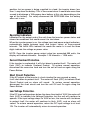
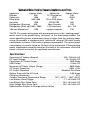
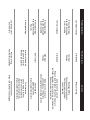
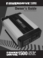
powerdriveinverters.com
Owner’s Guide
Please Save for Future Reference
1500
1500 Watt
DC to AC
Power Inverter
Thank you for purchasing the POWERDRIVE1500 power inverter, a high
performance solution to using household power while on the road. Please read
and understand all of the information provided in this manual before operating or
installing. If properly used, the inverter will give you years of reliable service
providing AC power for TVs, computers, appliances, stereos and power tools. For
safe and optimum performance, the inverter must be installed and used properly.
Carefully read and follow the guidelines in this manual giving special attention to
the CAUTION and WARNING statements. Keep this manual for reference should
troubleshooting be necessary.
CAUTION statements provide information that could damage your inverter or
equipment connected to it.
WARNING statements provide information on conditions that could result in
personal injury or loss of life.
WARNING: Incorrect installation or misuse of the RPPD1500 could result in
personal injury or damage to the inverter and/or attached equipment. Read
and follow the directions in the owner’s manual. The ROADPRO RPPD1500
produces the same potentially lethal AC power as normal household outlets.
It is suggested that you treat it with the same respect that you would any AC
outlet.
WARNING: SHOCK HAZARD, KEEP AWAY FROM CHILDREN.
DO NOT insert any foreign objects into the RPPD1500’s outlets, vents or fan
openings.
DO NOT expose the RPPD1500 to rain, water or any other liquids.
DO NOT connect the RPPD1500 to utility power distribution systems or
branch circuits.
WARNING: HEATED CASE AND SURFACE.
The case to the RPPD1500 may become very warm under high power
operation reaching 140°F. Be sure that there is at least 4 inches of
unobstructed air space around the entire surface of the inverter at all times.
During use, DO NOT place materials that could be damaged by heat on or
near the RPPD1500.
WARNING: EXPLOSION HAZARD.
DO NOT operate the RPPD1500 near flammable fumes or gases such as the
bilge of a gasoline power boat, or near propane tanks.
DO NOT operate the RPPD1500 in an enclosed area that contains automotive
type lead-acid batteries. This type of battery emits explosive hydrogen gas
which can be ignited by sparks.
CAUTION:
DO NOT connect the RPPD1500 to live AC power circuits. Damage to the
inverter will result even if the power switch is in the OFF position.
DO NOT connect any AC device which has its neutral conductor connected
to ground.
DO NOT expose the RPPD1500 to air temperatures in excess of 104°F.
DO NOT use the RPPD1500 on the following items:
1. Small battery-operated appliances such as flashlights, razors and
nightlights that can be plugged directly into an AC outlet to recharge.
2. Certain battery chargers for battery packs used in hand power tools. These
chargers will have a “Warning Label” indicating that dangerous voltages
are present at the battery terminals.
RPPD1500 Waveform Output:
The output waveform of your RPPD1500 is referred to as “square wave” or
“modified sine wave.” Some very sensitive electronic equipment and some
medical equipment (listed below) may not operate satisfactorily on “square
wave” or “modified sine wave.” It is a stepped waveform designed to have
characteristics similar to the pure sine wave shape of utility power. A
waveform of this nature is suitable for most AC loads (including linear and
switching power suppliers used in electronic equipment, transformers and
motors).
The problems described above, do not occur with most battery-operated
equipment. The vast majority of these items use a separate charger or
transformer that plugs into the AC outlet and produces a low voltage output.
If the label on your adapter states that it produces a low voltage (AC or DC)
output (30 volts or less) then the RPPD1500 will operate the item safely.
Some of the following items may not operate properly on a “square wave”
inverter. If you have any questions, contact the device’s manufacturer.
• Laser printers, photocopiers, magneto-optical hard drives.
• Certain laptop computers.
• Some fluorescent lights with electronic ballasts.
• Power tools employing “solid state” power or variable speed control.
• Some battery chargers for cordless tools.
• Digital clocks with radios.
• Medical equipment such as oxygen concentrators, nebulizers, and CPAP
machines.
INSTALLATION:
Selecting a suitable location
The RPPD1500 must be installed in an area that meets the following requirements in
order to operate safely and provide optimum performance:
1. DRY: DO NOT expose the unit to moisture.
2. COOL: Ambient air temperature should be between 32°F and 104°F. Cooler
areas are best.
3. VENTILATION: Allow at least 4 inches of clearance above and around all
sides and top of the unit for proper cooling.
4. SAFE: DO NOT install the RPPD1500 in a compartment with batteries or
flammable liquids or vapors such as gasoline or propane.
5. CLEAN: DO NOT install the RPPD1500 in an area that is prone to dirt, dust
or debris. This is especially important if used in a work environment.
Connecting DC Power Cables: Red +, Black – (included with inverter)
1. Reversing the polarity of the cables (positive to negative) will result
in damage to the RPPD1500 and will void the warranty.
2. For safety, disconnect the RPPD1500 from the battery when not in use.
3. Use grommets to protect cables from bare metal edges when installing
through firewalls or bulkheads.
4. Use only the cables supplied with this unit. Using longer cables will require
a thicker cable to reduce or minimize voltage drop to inverter.
The power cable is very important to the performance of the inverter. Because
the inverter has a low voltage, high current input, low resistance wiring is
essential between the battery and inverter. This is so it can deliver the
maximum amount of energy to the load. Keep the cable length as short as
possible, no more than four feet (one and a half meters). This will keep the
voltage drop to a minimum. If the cable has too much voltage drop, the
inverter may shut down when drawing higher currents because voltage at the
inverter may drop below 10.5 volts. If you must use longer cables (up to 10
feet), choose thicker cables, such as # Ø AWG, and trim the ends of the cable
to fit the terminals.
Connect the Power Cables to the Inverter:
Connect cable to the Power Input Terminals on input end of the inverter.
The red terminal is positive (+) and the black terminal is negative (-).
Unscrew the terminal on the inverter and install the appropriate color (black
to black and red to red) ring-terminal of the cables and tighten the screws to
clamp the wires securely.
NOTE: It is a good idea to check and tighten these screws from time to time.
They can become loose by vibrations or thermal cycling. Loose connectors
result in excessive voltage drop and may cause overheated wires and melted
insulation.
Connect the Power Cables to the Battery:
1. Connect the cable from the Negative Terminal (Black) of inverter to the
Negative Terminal of the battery.
2. Connect the cable from the Positive Terminal (Red) of the inverter to the
Positive Terminal of the battery. You might observe a spark when you make
this connection since current can flow to charge capacitors in the inverter.
CAUTION: Reversing the polarity of these cables (positive to negative) will
result in damage to the RPPD1500 and will void the warranty.
3. The inverter is now ready to deliver AC power to your loads. Press the
Power Button to on. If several loads are to be operated by the inverter, turn
them on separately, after the inverter has been turned on. This will ensure
that the inverter does not have to deliver the starting currents required for
all the loads at once.
CAUTION:
Connect the RPPD1500 to batteries with a normal output of 12-volts DC only.
6-volt batteries do not supply enough voltage, and a 24-volt battery supplies
too much voltage and will damage the RPPD1500. Never work on the AC
wiring without first physically disconnecting the DC connections.
CAUTION:
Never disconnect the DC cables from the inverter without first disconnecting
the cables from the battery or potentially lethal electricity will be left exposed.
NOTE: The Power Button turns the control circuit in the inverter on and off. It
does not disconnect power from the inverter. When the button is in the off
position, the inverter draws no current from the battery. When it’s in the on
position, but no power is being supplied to a load, the inverter draws less
than ½ amp from the battery. This is low current draw. It would take more than
a week to discharge a 100 ampere hour battery at this rate depending on the
age of the battery. For safety disconnect the RPPD1500 from the battery
when not in use.
Input Voltage
Output Wattage
Output Kilowatts
Operating Indicators:
Indicators on the output end of the unit show the inverters power status and
alarms for conditions that could cause it to shut down.
When the inverter power is on, the voltage input and power output indicators,
automatically toggle between input and output values at three-second
intervals. The three LEDs indicate the mode the meter is in and the three
digits indicate the voltage or power value.
NOTE: Once the inverter power output value has exceeded 999 watts, the
display will indicate kilowatts. Example: 1.25 kilowatts = 1250 watts.
Current Overload Protection:
If the inverter is overloaded, it will shut down to protect itself. The meter will
flash (OLP) to indicate Overload Protect. To restore normal operation,
disconnect the excessive load and turn the unit off and on again using the
Power Button.
Short Circuit Protection:
If the AC output of the inverter is short circuited for one second or more,
it will shut down to protect itself. The meter will flash (OPP) to indicate Short
Circuit Protect and an alarm will sound. To restore normal operation,
disconnect the short circuit and turn the unit Off and On again using the
Power Button.
Low Voltage Protection:
If the DC input voltage drops below the alarm threshold of 10.5V the meter will
flash (LUP) to indicate Low Voltage Protection, but the unit will continue to
operate. If the input voltage drops to 10.0V or less, the inverter will shut down
to protect itself, the meter will continue to flash (LUP), and an alarm will
sound. To restore normal operation, return the DC input voltage to at least
12V. The inverter will automatically return to normal operation.
High Voltage Protection:
If the DC input voltage rises above 15.0V, the inverter will shut down to protect
itself, the meter will flash (OUP) to indicate Over Voltage Protection, and an
alarm will sound. To restore normal operation, return the DC input voltage to
less than 15V. The inverter will automatically return to normal operation.
CAUTION: Although the inverter has protection against over-voltage, it may
still be damaged if the input voltage were to exceed 16 volts.
Over Temperature Protection:
If the internal inverter temperature rises above the alarm threshold, the meter
will flash (OCP) an alarm will sound to indicate over temperature protection,
and the unit will continue to operate. If the internal temperature rises to 104ºF,
the inverter will shut down to protect itself, the meter will continue to flash,
and the alarm will continue to sound.
NOTE: Internal inverter temperature can rise due to being operated in a high
heat environment or due to the fan or vents being blocked during operation
(even in relatively cool outside air). To restore normal operation, turn the unit
off and allow it to cool. The inverter will automatically return to normal
operation after it has cooled.
Remote On/Off Switch:
An optional Remote On/Off Switch can be connected to the Remote Jack
allowing you to turn the power inverter on or off from a convenient location
when the inverter is installed in an out of reach location.
USB Outlet; The USB outlet will supply 5 volts at 500ma to charge and power
cell phones, iPods® and other small electronics.
Operating Limits
Power Output:
The inverter can deliver 1500 watts for about 60 minutes. The inverter must
cool for 15 minutes before it can resume operation at 1500 watts.
NOTE: The wattage rating applies to resistive loads. The inverter will operate
most AC loads within its power rating. Some induction motors used in
freezers, pumps, and other motor-operated equipment require very high
surge currents to start. The inverter may not be able to start some of these
motors even though their rated current draw is within the inverter’s limits.
Operating time will vary depending upon the type, capacity charge level of the
battery, and the power draw of the AC products you are using. With a normal
vehicle battery and a 100 watt load (such as a small television) you can
expect an operating time of 2 to 3 hours. It is recommended that you start
your vehicle once an hour when using the RPPD1500 for extended periods of
time to prevent draining the battery.
WARNING: To prevent personal injury or loss of life, never start or leave your
engine running in a poorly ventilated area such as a garage.
Helpful Formulas:
To Convert AMPS to WATTS: AMPS X VOLTS = WATTS
To Convert WATTS to AMPS: WATTS ÷ VOLTS = AMPS
These formulas yield a close approximation of the continuous loads of a
product.
To calculate approximate Startup Load:
Multiply: WATTS X 2 = Starting Load
This formula yields a close approximation of the starting load of the
appliance, although some may require an even greater starting load. NOTE:
Induction motors such as air conditioners, refrigerators, freezers and pumps
may have a start up surge of 3 to 7 times the continuous rating. Most often
the start up load of the appliance or power tool determines whether an
inverter has the capability to power it.
For example: You have a freezer with a continuous load of 4 amps, and a start
up load of 12 amps:
4 amps x 120 volts = 480 watts continuous, 12 amps x 120 volts = 1440 watts
starting load
You would need an inverter with peak-surge rating greater than 1440 watts to
run this appliance.
FORMULA to convert AC Watts to DC Amps:
AC Watts divided by 12 x 1.1 = DC Amps
This is the size vehicle alternator you would need to keep up with a specific
load; for example, to keep up with a continuous draw of 1000 watts, you
would need a 91 amp alternator.
To calculate the total watt-hours of energy consumption:
Multiply the power by the operating time. To determine how many 12-volt amp
hours will be consumed, divide the watt hours by 10.
Example: 150 Watts x 1 Hour = 150 Watt Hours
150 Watt Hours ÷ 10 = 15 12 Volt Amp Hours
Estimated Watts Used by Common Appliances and Tools
Appliance
Approx. Watts
Blender
300
Coffee pot
1500
Blow dryer
900-1500
Hot plate
1200
Refrigerator (Running)
600
Refrigerator (Start up) 1800 » 3600
700 watt Microwave*
1100
Appliance
12" 3 speed fan
VCR
CD or DVD player
SONY PS3
Xbox Console
LCD television
Laptop computer
Approx. Watts
230
40-60
35
360
100
50 » 150
150
*NOTE: The power rating given with microwave ovens is the “cooking power”
which refers to the power being “delivered” to the food being cooked. The
actual operating power requirement rating is higher than the cooking power
rating (for example, a microwave with “advertised” rating of 700 watts usually
corresponds to almost 1100 watts of power consumption). The actual power
consumption is usually stated on the back of the microwave. If the operating
power requirement cannot be found on the back of the microwave, check the
owner’s manual or contact the appliance manufacturer.
Specifications:
Operating AC Voltage (Normal) . . . . . . . . . . . . . . . . . . . . . . 105~125-Volts AC
DC Input Voltage . . . . . . . . . . . . . . . . . . . . . . . . . . . . . . . . . . . . 10~15-Volts DC
Continuous AC Power Output . . . . . . . . . . . . . . . . . . . . . . . . . . . . . 1500 Watts
USB Output . . . . . . . . . . . . . . . . . . . . . . . . . . . . . . . . . . . . . . . . . . . . 5 Volts DC
Maximum AC Power Output (Surge) . . . . . . . . . . . . . . . . . . . . . . . . 3000 Watts
AC Output Frequency . . . . . . . . . . . . . . . . . . . . . . . . . . . . . . . . . . 60Hz ±2Hz
AC Output Waveform . . . . . . . . . . . . . . . . . . . . . . . . . . . . Modified Sine Wave
Battery Drain with No AC Load . . . . . . . . . . . . . . . . . . . . . . . . . . . . . 0.50 Amps
Efficiency (Maximum). . . . . . . . . . . . . . . . . . . . . . . . . . . . . . . . . . . . . . . . . . 87%
Ambient Operating Temperature Range. . . . . . . . 14°F (-10°C) ~ 104°F (40°C)
Low Battery Alarm Trigger . . . . . . . . . . . . . . . . . . . . . . . . . . . 11 ±0.3-Volts DC
Low Battery Shut Down Point . . . . . . . . . . . . . . . . . . . . . . 10.5 ±0.3-Volts DC
High Voltage Shut Down Point . . . . . . . . . . . . . . . . . . . . . . 15.5 ±0.5-Volts DC
Specifications Subject to Change without Notice
No output voltage
Red LED illuminated
Alarm sounding
No output voltage
Red LED illuminated
Alarm sounding
Low output voltage
Problem/Symptom
Inverter switched off
No power to inverter
Reverse DC polarity
Short circuit
High input
voltage
Overloaded
Low input
Voltage
Overloaded
Possible Causes
Check connections.
Make sure battery is fully charged.
Turn inverter on
Check wiring to inverter.
Observe correct polarity
(black to black/red to red).
Inspect cables from battery.
Check load for
proper operation.
Inspect cables from battery.
Make sure the inverter is
connected to a 12V battery.
Check regulation of charging systems
Allow inverter to cool off.
Reduce load. Improve ventilation; make sure
ventilation openings in the inverter are not obstructed.
Reduce ambient temperature.
Recharge battery.
Check connections and cable.
Continuous operation input
current required.
Reduce the load.
Solution
No output voltage
Thermal shutdown
No output voltage
Red LED illuminated
No alarm
Poor DC wiring
Poor battery condition
Low battery alarm
on all the time
This Limited One Year Warranty from POWERDRIVE, a DAS brand, applies to all
electronic products and devices manufactured by DAS Distributors and sold under the
brand name POWERDRIVE.
Terms of the Warranty:
POWERDRIVE warrants that the product you have purchased from a DAS authorized
retailer is free from defects in materials and workmanship under normal use during the
warranty period. The warranty period begins on the day of retail sale. This warranty
extends only to the original purchaser. It is not transferable to anyone who subsequently
receives the product. It excludes all expendable parts (fuses, etc). During the warranty
period POWERDRIVE will repair your defective product, replace it with an identical item,
or at our option exchange it for an equivalent product of value and performance. This
Limited Warranty does not extend to any product that has been damaged or rendered
defective as a result of: an accident, misuse or abuse, as a result of an act of God, by
operation outside the usage parameters stated in this manual, by modification of the
product, attempted repair, or as a result of war or terrorist attack. Other limitations of this
warranty exclude; payment for your lost time, loss of use of your product, or property
damage caused by the product or its failure to work, or any other incidental or
consequential damages including personal injury. Except as expressly set forth in this
warranty statement, POWERDRIVE makes no other warranties expressed or implied.
Defective products must be returned to the dealer within 30 days, after 30 days, the
product may be returned to POWERDRIVE.
When returning products to POWERDRIVE: Shipping to POWERDRIVE shall be prepaid,
your replacement will be mailed back to you at no additional charge. Carefully pack
product and all included accessories into a suitable box, along with original dated
register receipt or invoice, a letter stating the defect, daytime phone number, and a
physical return address. (UPS will not deliver to a PO Box.)
• Any package with a PO Box address will not be processed, and will be held until
further notification from you.
• Make sure you can track your shipment to us. POWERDRIVE will not be responsible
for lost packages.
• POWERDRIVE will not be responsible for damage incurred during shipment to us.
• Failure to provide a dated proof of purchase will invalidate warranty.
Ship to:
POWERDRIVE Returns
1875 Zeager Road, Elizabethtown, PA 17022
For customer assistance and technical support call 1-866-622-7979 Monday through
Friday 8:00am to 5:00pm Eastern Time. Or write to: [email protected]
1875 Zeager Road, Elizabethtown, PA 17022
© POWERDRIVE