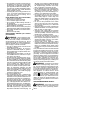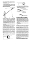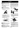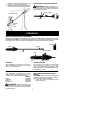
1
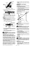
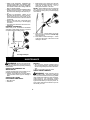
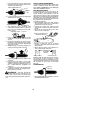
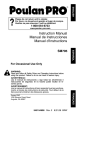
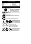
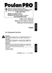
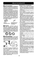
ENGLISH
R
Instruction Manual
Manual de Instrucciones
Manuel d’Instructions
PP5000P
ESPAÑOL
Electrolux Home Products, Inc.
104 Warren Road
Augusta, GA 30907
Copyright E2004 Electrolux Home Products, Inc.
530163467
7/16/04
FRANÇAIS
WARNING:
Read and follow all Safety Rules and Operating Instructions before
using this product. Failure to do so can result in serious injury.
ADVERTENCIA:
Lea el manual de instrucciones y siga todas las advertencias e
instrucciones de seguridad. El no hacerlo puede resultar en lesiones graves.
AVERTISSEMENT:
Lire le manuel d’instructions et bien respecter tous les avertissements et toutes les instructions de sécurité. Tout défaut de le
faire pourrait entraîner des blessures graves.
IDENTIFICATION OF SYMBOLS
DANGER! This pruner can
be dangerous! Careless or improper use can cause
serious or even fatal injury.
Read and understand the
instruction manual before
using the pruner.
Always wear appropriate ear protection, eye protection and head protection.
DANGER!
Falling objects can cause severe head injury. Wear head
protection when operating this unit. Do not stand beneath branch being
cut.
SAFETY RULES
Hearing
Protection
WARNING:
Always disconnect spark
plug wire and place wire where it cannot contact
spark plug (or disconnect powerhead from
power source) to prevent accidental starting
when setting up, transporting, adjusting or making repairs except carburetor adjustments.
Snug
Fitting
Clothing
Because a pruner is a high-speed wood-cutting
tool, special safety precautions must be observed to reduce the risk of accidents. Careless
or improper use of this tool can cause serious or
even fatal injury.
Safety
Shoes
Safety Hat
Eye
Protection
Heavy Duty
Gloves
Safety Chaps
PLAN AHEAD
S Read this manual carefully until you completely understand and can follow all safety
rules, precautions, and operating instructions
before attempting to use the unit.
S Restrict the use of your pruner to adult users
who understand and can follow safety rules,
precautions, and operating instructions found
on the unit and in this manual.
S Keep all parts of your body away from the
chain when the engine is running.
S Keep children, bystanders, and animals a
minimum of 50 feet (15 meters) away from
the work area. Do not allow other people or
animals to be near when starting or operating the pruner.
HAZARD ZONE
INSTRUCTION
MANUAL
SAFETY INFORMATION
ON THE UNIT
S Wear protective gear. Always use steeltoed safety footwear with non-slip soles;
snug-fitting clothing; heavy, long pants, and
long sleeves; heavy-duty, non-slip gloves;
eye protection such as non-fogging, vented
goggles or face screen; an approved safety
hard hat; and sound barriers (ear plugs or
mufflers) to protect your hearing. Regular
users should have hearing checked regularly as engine noise can damage hearing.
Secure hair above shoulder length. Secure
or remove loose clothing and jewelry or
clothing with loosely hanging ties, straps,
tassels, etc.
50 feet
(15 meters)
DANGER: Do not
use near electrical
wires or power lines.
Keep pruner at least
30 feet (10 meters)
away from all power
lines.
2
S Do not handle or operate a pruner when you
are fatigued, ill, or upset, or if you have taken
alcohol, drugs, or medication. You must be in
good physical condition and mentally alert. If
you have any condition that might be aggravated by strenuous work, check with doctor
before operating a pruner.
S Carefully plan your pruning operation in advance. Do not start cutting until you have a
clear work area, secure footing, and a
planned retreat path.
still does not fit, contact a qualified electrician
to install the proper wall outlet. Do not change
the equipment plug, extension cord receptacle, or extension cord plug in any way.
S Do not attempt to repair unit. Inspect the insulation and connectors on the powerhead and
extension cord before each use. If there is
any damage, do not use until damage is repaired by your authorized service dealer.
S Do not pull or carry by cord; do not use cord
as a handle, close a door on cord, or pull cord
around sharp edges or corners. Keep cord
away from heated surfaces. Do not unplug by
pulling on cord. To unplug, grasp the plug, not
the cord.
S Do not use the powerhead if the switch
does not turn the unit on and off properly.
Have the unit repaired by your authorized
service dealer.
S Keep the extension cord clear of operator and
obstacles at all times. Do not expose cords to
heat, oil, water, or sharp edges.
S Avoid any body contact with any grounded
conductor, such as metal fences, or pipes, to
avoid the possibility of electric shock. Don’t
handle plug or unit with wet hands.
S Do not use with damaged cord or plug. If
powerhead is not working as it should, has
been dropped, damaged, left outdoors, or
dropped into water, return it to your authorized service dealer for repair.
S Ground Fault Circuit Interrupter (GFCI)
protection should be provided on the circuit or
outlet to be used for the powerhead. Receptacles are available having built-in GFCI
protection and may be used for this measure
of safety.
Your powerhead should be double insulated
to help protect against electric shock. Double
insulation construction consists of two separate “layers” of electrical insulation instead of
grounding. Tools and appliances built with a
double insulation system are not intended to
be grounded. Safety precautions must be observed when operating any electrical tool.
The double insulation system only provides
added protection against injury resulting from
an internal electrical insulation failure.
FUEL SAFETY (for gas powerheads)
S
S
S
S
S
S
S
S
Mix and pour fuel outdoors.
Keep away from sparks or flames.
Use a container approved for fuel.
Do not smoke or allow smoking near fuel or
the powerhead.
Avoid spilling fuel or oil. Wipe up all fuel spills
before starting the powerhead.
Move at least 10 feet (3 meters) away from
fueling site before starting powerhead engine.
Stop engine and allow to cool before removing fuel cap.
Remove fuel cap slowly.
ELECTRICAL SAFETY (for electric
powerheads)
WARNING: Avoid a dangerous environment. To reduce the risk of electrical shock,
do not use in rain, in damp or wet locations, or
around swimming pools, hot tubs, etc. Do not
expose to snow, rain, or water to avoid the possibility of electrical shock. Do not handle extension cord plug or unit with wet hands.
S Use only a voltage supply as shown on the
nameplate of the unit.
S Avoid dangerous situations. Do not use in
presence of flammable liquids or gases to
avoid creating a fire or explosion and/or causing damage to unit.
S Avoid dangerous environments. Do not use
in unventilated areas or where dust or explosive vapors can build up.
S To reduce the risk of electrical shock, use extension cords specifically marked as suitable
for outdoor appliances. The electrical rating of
the cord must not be less than the rating of the
unit. The cord must be marked with the suffix
“W-A” (in Canada, “W”). Make sure your extension cord is in good condition. Inspect extension cord before use and replace if damaged. An undersized extension cord will
cause a drop in line voltage resulting in loss of
power and overheating. If in doubt, use the
next heavier gauge. The smaller the gauge
number, the heavier the cord.
S Do not use multiple cords.
S The powerhead may have a polarized plug
(one blade is wider than the other); if so, it will
require the use of a polarized extension cord.
The appliance plug will fit into a polarized extension cord only one way. If the plug does
not fit fully into the extension cord, reverse the
plug. If the plug still does not fit, obtain a correct polarized extension cord. A polarized extension cord will require the use of a polarized
wall outlet. This plug will fit into the polarized
wall outlet only one way. If plug does not fit
fully into the wall outlet, reverse the plug. If it
WARNING: All repairs to an electric
powerhead, including housing, switch, motor,
etc., must be diagnosed and repaired by qualified service personnel. Replacement parts
for a double insulated appliance must be identical to the parts they replace. A double insulated appliance is marked with the words
“double insulation” or “double insulated”. The
(square within a square) may also
symbol
be marked on the appliance. Failure to have
the unit repaired by your authorized service
dealer can cause the double insulation construction to become ineffective and result in
serious injury.
UNIT/MAINTENANCE SAFETY
3
WARNING: Disconnect powerhead
spark plug (or disconnect powerhead from
power source) before performing maintenance.
S Inspect entire unit before each use. Replace
damaged parts. Check for fuel leaks. Make
sure all fasteners are in place and securely
fastened.
S Maintain unit according to recommended procedures.
S Use only recommended Poulan PRO®
parts and accessories. Never use wire,
wire rope, string, flailing devices, etc.
S Be sure chain stops moving when engine
idles (see CARBURETOR ADJUSTMENTS section of powerhead manual).
S Keep others away when making carburetor
adjustments.
S Never start the unit with the clutch housing removed. The clutch can fly off and cause serious injury.
S Keep the handles driy, clean, and free of oil or
fuel mixture.
S Keep fuel and oil caps, screws, and fasteners
securely tightened.
S Have all maintenance and service not explained in this manual performed by an authorized service dealer.
another. Stop the engine before setting the
unit down.
S Use only in daylight or good artificial light.
S Use only for jobs explained in this manual (or
manuals for optional attachments).
KICKBACK
WARNING: Avoid kickback which
can result in serious injury. Kickback is the
backward, upward or sudden forward motion
of the guide bar occurring when the chain
near the upper tip of the guide bar contacts
any object such as a log or branch, or when
the wood closes in and pinches the chain in
the cut. Contacting a foreign object in the
wood can also result in loss of control.
S Rotational Kickback can occur when the
moving chain contacts an object at the upper
tip of the guide bar. This contact can cause
the chain to dig into the object, which stops
the chain for an instant. The result is a lightning fast, reverse reaction which kicks the
guide bar up and back toward the operator.
S Pinch-Kickback can occur when the wood
closes in and pinches the moving chain in
the cut along the top of the guide bar and the
chain is suddenly stopped. This sudden
stopping of the chain results in a reversal of
the chain force used to cut wood and
causes the pruner to move in the opposite
direction of the chain rotation. The pruner is
driven straight back toward the operator.
S Pull-In can occur when the moving chain
contacts a foreign object in the wood in the cut
along the bottom of the guide bar and the
chain is suddenly stopped. This sudden stopping pulls the pruner forward and away from
the operator and could easily cause the operator to lose control of the pruner.
OPERATE YOUR PRUNER SAFELY
S Do not operate a pruner with one hand. Serious injury to the operator, helpers, bystanders or any combination of these persons may result from one-handed
operation. A pruner is intended for twohanded use.
S Operate the pruner only in a well-ventilated
outdoor area.
S Do not operate pruner from a ladder or in a
tree.
S Do not use a pruner to cut down trees or any
portion of the tree trunk.
S Only use for pruning limbs or branches
overhead not greater than 4 inches (10 cm)
in diameter.
S Never stand under the limb you are pruning.
Always position yourself out of the path of falling debris.
S Do not cut small brush and saplings with the
pruner. Slender matter may catch in the chain
and be whipped toward you, pulling you off
balance.
S Make sure the chain will not make contact
with any object while starting the engine.
Never try to start the unit when the guide
bar is in a cut.
S Do not put pressure on the pruner at the end
of the cut. Applying pressure can cause you
to lose control when the cut is completed.
S Do not run the unit at high speed when not
pruning.
S If you strike or become entangled with a foreign object, stop the engine immediately and
check for damage. Have any damage repaired by an authorized service dealer before
attempting further operations.
S Do not operate a pruner that is damaged, improperly adjusted, or not completely and securely assembled. Always replace bar and
chain immediately if it becomes damaged,
broken or is otherwise removed.
S Always stop the unit when work is delayed or
when walking from one cutting location to
REDUCE THE CHANCE OF
KICKBACK
S Recognize that kickback can happen. With
a basic understanding of kickback, you can
reduce the element of surprise which contributes to accidents.
S Never let the moving chain contact any object at the tip of the guide bar.
S Keep the working area free from obstructions such as other trees, branches, rocks,
stumps, etc. Eliminate or avoid any
obstruction that your chain could hit while
you are cutting. When cutting a branch, do
not let the guide bar contact branch or other
objects around it.
S Keep your chain sharp and properly tensioned. A loose or dull chain can increase
the chance of kickback occurring. Follow
manufacturer’s chain sharpening and
maintenance instructions. Check tension
at regular intervals with the engine stopped,
never with the engine running. Make sure
the bar clamp nut is securely tightened after
tensioning the chain.
S Begin and continue cutting at full speed. If
the chain is moving at a slower speed, there
is greater chance of kickback occurring.
S Cut one branch at a time.
4
S Use extreme caution when re-entering a
previous cut.
S Do not attempt cuts starting with the tip of
the bar (plunge cuts).
S Watch for shifting of wood or other forces that
could close a cut and pinch or fall into chain.
S Use the Reduced--Kickback Guide Bar and
Low--Kickback Chain specified for your unit.
Symmetrical Guide Bar
Large Radius Tip
S Low--Kickback Chain, designed with a contoured depth gauge and guard link which
deflect kickback force and allow wood to
gradually ride into the cutter.
MAINTAIN CONTROL
Contoured Depth Gauge
Elongated Guard Link
Low--- Kickback
Chain
Deflects
kickback force
and allows wood
to gradually ride
into cutter
Can Obstruct Material
Not a Low--- Kickback Chain
TRANSPORTING AND STORAGE
S Do not grasp or hold exposed blade.
S Stop powerhead before leaving work area.
S Allow powerhead and gearbox to cool before
storing or transporting it in a vehicle.
S Store unit and fuel in area where fuel vapors
cannot reach sparks or open flames from water heaters, electric motors or switches, furnaces, etc.
S Store attachment so blade cannot accidentally cause injury.
S Store attachment indoors, out of reach of children.
If situations occur which are not covered in
this manual, use care and good judgment. If
you need assistance, call 1-800-554-6723.
SPECIAL NOTICE: Exposure to vibrations through prolonged use of gasoline powered hand tools could cause blood vessel or
nerve damage in the fingers, hands, and
joints of people prone to circulation disorders
or abnormal swellings. Prolonged use in cold
weather has been linked to blood vessel damage in otherwise healthy people. If symptoms
occur such as numbness, pain, loss of
strength, change in skin color or texture, or
loss of feeling in the fingers, hands, or joints,
discontinue the use of this tool and seek medical attention. An anti-vibration system does
not guarantee the avoidance of these problems. Users who operate power tools on a
continual and regular basis must monitor
closely their physical condition and the condition of this unit.
S Keep a good, firm grip on the pruner with
both hands when the engine is running and
don’t let go. A firm grip will help you reduce
kickback and maintain control. Keep the fingers of your left hand encircling and your
left thumb under the assist handle. Keep
your right hand completely around the
throttle handle whether your are right handed or left handed.
S Stand with your weight evenly balanced on
both feet.
S Stand slightly to the left side of the pruner to
keep your body from being in a direct line
with the cutting chain.
KICKBACK SAFETY FEATURES
The following features are included on your
pruner to help reduce the hazard of kickback;
however, such features will not totally eliminate this danger. As a pruner user, do not rely
only on safety devices. You must follow all
safety precautions, instructions, and maintenance in this manual to help avoid kickback
and other forces which can result in serious
injury.
S Reduced--Kickback Guide Bar, designed
with a small radius tip which reduces the
size of the kickback danger zone on the bar
tip.
Reduced Kickback Symmetrical Guide Bar
Small Radius Tip
SAVE THESE INSTRUCTIONS
5
ASSEMBLY
NOTE: The lower shoulder strap clamp has
WARNING:
two spacer tabs attached. These tabs are
provided to adapt this attachment for use with
powerheads that have a 1″ diameter upper
shaft (the shoulder strap clamp will not tighten
down securely on the 1″ diameter upper shaft
without using these spacer tabs). The tabs
must be broken off completely before use and
placed over the screw holes on the lower
shoulder strap clamp. These tabs are not
needed for powerheads with a 7/8″ upper
shaft.
If received assembled,
repeat all steps to ensure your unit is properly
assembled and all fasteners are secure.
Examine parts for damage. Do not use damaged parts.
NOTE: If you need assistance or find parts
missing or damaged, call 1-800-554-6723.
TOOLS REQUIRED
S Hex wrench (provided)
INSTALLING PRUNER ATTACHMENT
CAUTION: When removing or installing at-
LOWER SHOULDER STRAP
CLAMP
tachments, place the unit on a flat surface for
stability.
1. Loosen the coupler by turning the knob
counterclockwise.
Spacer Tabs
Coupler
Spacer Tabs
positioned for use
on 1″ diameter
upper shaft
LOOSEN
TIGHTEN
1. Place the upper shoulder strap clamp
over the upper shaft above the handlebar.
2. Position the lower shoulder strap clamp
under the upper shaft and align the upper
and lower clamp screw holes (use spacer
tabs between upper and lower clamps if
necessary to secure clamp, i.e. for 1″ diameter upper shaft).
Knob
2. Remove the shaft cap from the pruner attachment (if present).
3. Position locking/release button of attachment into guide recess of coupler.
4. Push the attachment into the coupler until
the locking/release button snaps into the
primary hole.
5. Before using the unit, tighten the knob securely by turning clockwise.
Coupler
Upper
Shaft
Upper Shoulder
Strap Clamp
POWERHEAD
END
Primary Hole
Guide Recess
Locking/
Release
Button
Lower Shoulder
Strap Clamp
Lower
Attachment
WARNING:
Make sure the locking/
release button is locked in the primary hole
and the knob is securely tightened before operating the unit.
SHOULDER STRAP ASSEMBLY
WARNING: Proper shoulder strap and
handle adjustments are required before use.
The shoulder strap clamp must be installed as
shown above the assist handle on the upper
shaft (powerhead end of unit).
6
ATTACHMENT
END
Screws
3. Insert two screws into the screw holes.
4. Secure shoulder strap clamp by tightening screws with the hex wrench.
5. Try on shoulder strap and adjust for fit and
balance before starting the engine or beginning a cutting operation.
6. Insert your right arm and head through the
shoulder strap and allow it to rest on your
left shoulder. Make sure the danger sign
is on your back and the hook is to the right
side of your waist.
NOTE: A one-half twist is built in the shoulder strap to allow the strap to rest flat on the
shoulder.
ADJUSTING THE ASSIST HANDLE
7. Adjust the strap, allowing the hook to be
about 3 -- 6 inches below the waist.
8. Fasten the strap hook to the upper clamp
and lift the tool to the operating position.
WARNING: When adjusting the assist handle, be sure it remains directly above
the coupler on the engine end shaft to ensure
proper balancing of unit.
Assist Handle
Shoulder Strap
Coupler
Shoulder
Strap
Clamp
OPERATION
KNOW YOUR PRUNER ATTACHMENT
READ THIS INSTRUCTION MANUAL AND SAFETY RULES BEFORE OPERATING YOUR
PRUNER ATTACHMENT. Compare the illustrations with your attachment to familiarize yourself with
the location of the various controls and adjustments. Save this manual for future reference.
Hanger
Pruner
Coupler
Shaft
Bar oil fill cap
Chain
Bar
Bar nut
PRUNER
CHAIN TENSION
OPERATING THE COUPLER
REMOVING PRUNER ATTACHMENT
(OR OTHER OPTIONAL ATTACHMENTS)
CAUTION: When removing or installing at-
The PRUNER is designed for removal of
limbs and branches overhead not greater
than 4 inches in diameter.
It is normal for a new chain to stretch during
first 15 minutes of operation. You should
check your chain tension frequently. See
CHAIN TENSION in the SERVICE AND ADJUSTMENTS section.
Your powerhead is equipped with a coupler
which enables optional attachments to be
installed. The optional attachments are:
MODEL:
Edger . . . . . . . . . . . . . . . . . . . . . . . PP1000E
Cultivator . . . . . . . . . . . . . . . . . . . . PP2000T
Blower . . . . . . . . . . . . . . . . . . . . . . PP3000B
Brushcutter . . . . . . . . . . . . . . . . . . PP4000C
WARNING: Always disconnect powerhead spark plug (or disconnect powerhead
from power source) before removing or installing attachments.
tachments, place the powerhead and attachment on a flat surface for stability.
1. Loosen the coupler by turning the knob
counterclockwise.
7
Upper Shaft
S Never use waste oil for bar and chain lubrication.
S Always stop the engine before removing
the oil cap.
Coupler
LOOSEN
Lower
Attachment
TIGHTEN
INSTALLING ATTACHMENT
HANGER
An attachment hanger is provided for storage
when attachment is not in use.
To install hanger on attachment:
1. Remove the shaft cap from the attachment
(if present) and discard.
2. Press and hold the locking/release button.
3. Push hanger onto the attachment until the
locking/release button snaps into the hole.
Knob
2. Press and hold the locking/release button.
Locking/Release
Button
OPERATING POSITION
ALWAYS WEAR:
Coupler
Lower Attachment
Head
Protection
Upper Shaft
Eye
Protection
3. While securely holding the upper shaft,
pull the attachment straight out of the coupler.
INSTALLING OPTIONAL ATTACHMENTS
Long Pants
1. Remove the shaft cap from the attachment
(if present) and discard.
2. Position locking/release button of attachment into guide recess of upper shaft coupler.
Coupler Primary Hole
Guide Recess
Heavy Shoes
DANGER: Do not extend arms above
shoulders while pruning. Do not stand beneath branch being cut.
Upper
Shaft
Locking/
Release
Button
WARNING: Always wear head, eye,
hearing, foot and body protection to reduce
the risk of injury when operating this unit.
When operating unit, clip shoulder strap onto
clamp, stand as shown and check for the following:
S Extend your left arm and hold assist handle
with your left hand.
S Hold throttle grip with your right hand with
finger on throttle trigger.
S Keep engine end below waist level.
S Keep shoulder strap pad centered on your
left shoulder and danger sign centered on
your back.
S Maintain full weight of tool on your left
shoulder.
Attachment
3. Push the attachment into the coupler until
the locking/release button snaps into the
primary hole.
4. Before using the unit, tighten the knob securely by turning clockwise.
WARNING: Make sure the locking/
release button is locked in the primary hole
and the knob is securely tightened before operating the unit.
BAR AND CHAIN LUBRICATION
The bar and chain require lubrication. The
chain oiler provides continuous lubrication to
the chain and guide bar. Be sure to fill the bar
oil tank before use (Capacity = 4.6 fl. oz.).
Lack of oil will quickly ruin the bar and chain.
Too little oil will cause overheating shown by
smoke coming from the chain and/or discoloration of the bar. The oil output is automatically
metered during operation.
Genuine PoulanR or Poulan PROR bar and
chain oil is recommended to protect your unit
against excessive wear from heat and friction. PoulanR or Poulan PROR oil resists
high temperature thinning. If PoulanR or
Poulan PROR bar and chain oil is not available, use a good grade SAE 30 oil.
PRUNING
WARNING: Be alert for and guard
against kickback. Do not allow the moving
chain to contact any other branches or objects at the nose of the guide bar when pruning. Allowing such contact can result in serious injury.
IMPORTANT POINTS
8
S Work slowly, keeping both hands firmly
gripped on the pruner. Maintain secure
footing and balance.
S Plan cut carefully. Check direction branch
will fall.
S Watch out for springpoles. Springpoles are
small size limbs which can catch the chain
and whip toward you or pull you off balance.
Use extreme caution when cutting small size
limbs or slender material.
S Watch out for branches immediately behind
the branch being pruned. If the chain hits
the rear branch, damage to the unit may occur.
S Be alert for springback. Watch out for
branches that are bent or under pressure.
Avoid being struck by the branch or the
pruner when the tension in the wood fibers
is released.
S Keep a clear work area. Frequently clear
branches out of the way to avoid tripping
over them.
S Long branches should be removed in several pieces.
1. Make the first cut 6 inches from the tree
trunk on the bottom of the limb. Use top of
guide bar to make this cut. Cut 1/3
through the diameter of the limb.
NOTE: When making the second and third
cuts, rest the foot of the pruner against the
tree limb that is being cut to prevent whipping
of the branch.
Foot
PRUNING TECHNIQUE
When ready to cut, accelerate to full throttle
and apply a light cutting pressure. DO NOT
use back and forth sawing action.
2. Next, move 2 -- 4 inches farther out on the
limb and make a second cut all the way
through the limb.
3. Then, make a final cut leaving a 1 -- 2 inch
collar from the trunk of the tree to avoid
damage to the tree.
Second cut
Third cut
Collar
First cut
Pruning technique
MAINTENANCE
INSPECT AND CLEAN UNIT AND
DECALS
WARNING:
Always stop unit and disconnect spark plug wire (or disconnect powerhead from power source) before performing
maintenance.
S After each use, inspect complete unit for
loose or damaged parts. Clean the unit and
decals using a damp cloth with a mild detergent.
S Wipe off unit with a clean dry cloth.
CHECK FOR DAMAGED OR
WORN PARTS
CHECK CHAIN TENSION
Contact an authorized service dealer for replacement of damaged or worn parts.
S Oil tank -- Discontinue use of pruner attachment if oil tank shows signs of damage or
leaks.
WARNING: Wear protective gloves
when handling chain. The chain is sharp and
can cut you even when it is not moving. Make
chain adjustments with lower end supported.
Chain tension is very important. Chains
stretch during use. This is especially true during the first few times you use your pruner. Always check chain tension each time you use
and refuel your unit.
CHECK FOR LOOSE
FASTENERS AND PARTS
S Bar clamp nut
S Fasteners
9
1. Use a screwdriver to move chain around
guide bar to ensure kinks do not exist. The
chain should rotate freely.
Chain Adjustment Tool
Guide
Bar
2. Loosen bar clamp nut until it is finger tight
against the bar clamp.
Adjusting Screw
Bar clamp nut
3. Turn adjusting screw clockwise until
chain solidly contacts bottom of guide bar
rail. Then, turn adjusting screw an additional 1/4 turn.
Adjusting Screw -- 1/4 Turn
CHECK CHAIN SHARPNESS
A sharp chain makes wood chips. A dull chain
makes a sawdust powder and cuts slowly.
See CHAIN SHARPENING in the SERVICE
AND ADJUSTMENTS section.
BAR MAINTENANCE
If your pruner cuts to one side, has to be
forced through the cut, or been run with an improper amount of bar lubrication it may be
necessary to service your bar. A worn bar will
damage your chain and make cutting difficult.
After each use, ensure ON/OFF switch is in
the OFF position, then clean all sawdust from
the guide bar and sprocket hole.
To maintain guide bar:
S Move ON/OFF switch to the OFF position
and disconnect spark plug (or disconnect
powerhead from power source).
S Loosen and remove bar clamp nut and
chain brake. Remove bar and chain from
pruner.
S Clean the oil holes and bar groove after
each 5 hours of operation.
Remove Sawdust From
Guide Bar Groove
4. Using a screwdriver, roll chain around
guide bar to ensure all links are in bar
groove.
5. Lift up tip of guide bar to check for sag.
Release tip of guide bar, then turn adjusting screw 1/4 turn clockwise. Repeat until
sag does not exist.
6. While lifting tip of guide bar, tighten bar
clamp nut securely with a wrench.
7. Use a screwdriver to move chain around
guide bar.
8. If chain does not rotate, it is too tight.
Slightly loosen bar clamp nut and loosen
chain by turning the adjusting screw 1/4
turn counterclockwise. Retighten bar
clamp nut.
9. If chain is too loose, it will sag below the
guide bar and needs to be tightened following above procedure.
WARNING: DO NOT operate the
pruner if the chain is loose. If the pruner is operated with a loose chain, the chain could
jump off the guide bar and result in serious injury.
Oil Holes
S Burring of guide bar rails is a normal
process of rail wear. Remove these burrs
with a flat file.
S When rail top is uneven, use a flat file to restore square edges and sides.
File Rail Edges
and Sides
Square
Worn Groove
Correct Groove
Replace guide bar when the groove is worn,
the guide bar is bent or cracked, or when
excess heating or burring of the rails occurs. If
replacement is necessary, use only the guide
bar specified for your pruner in the repair
parts list.
LUBRICATION
Bar Oil
Fill Cap
S See GUIDE BAR AND CHAIN OIL under
the OPERATION section.
10
SERVICE AND ADJUSTMENTS
Depth Gauge
Cutters
WARNING:
Always stop unit and disconnect spark plug wire (or disconnect powerhead from power source) before performing
maintenance, service, or adjustments except
for carburetor adjustments.
CHAIN SHARPENING
Drive Links
Chain sharpening is a complicated task that
requires special tools. We recommended you
refer chain sharpening to a professional chain
sharpener.
CHAIN REPLACEMENT
WARNING: Wear protective gloves
when handling chain. The chain is sharp and
can cut you even when it is not moving.
It is normal for a new chain to stretch during the
first 15 minutes of operation. You should recheck your chain tension frequently and adjust
the chain tension as required. See CHAIN TENSION section.
Replace the old chain when it becomes worn or
damaged. Use only the Low-Kickback replacement chain specified in the repair parts list.
TO REPLACE CHAIN:
1. Move ON/OFF switch to the OFF position
and disconnect spark plug (or disconnect
powerhead from power source).
2. Remove bar clamp nut.
3. Remove bar clamp.
4. Turn adjusting screw by hand counterclockwise until adjusting pin just touches
the stop.
5. Slide guide bar behind sprocket until
guide bar stops against sprocket.
6. Remove the old chain.
7. Carefully remove new chain from package. Hold chain with the drive links as
shown.
8. Place chain over sprocket, fitting the drive
links in the sprocket.
9. Fit bottom of drive links between the teeth in
the sprocket in the nose of the guide bar.
10. Fit chain drive links into bar groove.
11. Pull guide bar forward until chain is snug
in guide bar groove. Ensure all drive links
are in the bar groove.
12. Now, install bar clamp making sure the
adjusting pin is positioned in the lower
hole in the guide bar.
Lower Hole
Adjusting Pin
Cutter
Tip of
Bar
Guide Bar
Drivelink
CUTTERS MUST FACE IN
DIRECTION OF ROTATION
13. Install bar clamp nut and finger tighten
only. Do not tighten any further at this
point. Proceed to the CHAIN ADJUSTMENT section.
CHAIN ADJUSTMENT
See CHECK CHAIN TENSION in MAINTENANCE section.
11
STORAGE
WARNING:
Perform the following
steps after each use:
S Allow attachment to cool before storing or
transporting.
S Store attachment with all guards in place.
Position attachment so that any sharp object cannot accidentally cause injury.
S Store the attachment in a dry, well ventilated area out of the reach of children.
SEASONAL STORAGE
Prepare attachment for storage at end of season or if it will not be used for 30 days or more.
If your pruner attachment is to be stored for a
period of time:
S Clean the entire attachment.
S Lightly oil external metal surfaces and
guide bar.
S Oil the chain and wrap it in heavy paper or
cloth.
S Check entire attachment for loose screws
or nuts. Replace any damaged, worn or
broken parts.
S At the beginning of the next season, use
only fresh fuel having the proper gasoline to
oil ratio.
LIMITED WARRANTY
ELECTROLUX HOME PRODUCTS, INC.,
warrants to the original purchaser that each
new Poulan PRO® brand gasoline tool or attachment is free from defects in material and
workmanship and agrees to repair or replace
under this warranty any defective gasoline
product or attachment as follows from the
original date of purchase.
2 YEARS-- Parts and Labor, when used for
household purposes.
90 DAYS -- Parts and Labor, when used for
commercial, professional, or income producing purposes.
30 DAYS -- Parts and Labor, if used for rental
purposes.
This warranty is not transferable and does not
cover damage or liability caused by improper
handling, improper maintenance, or the use
of accessories and/or attachments not specifically recommended by ELECTROLUX
HOME PRODUCTS, INC., for this tool. Additionally, this warranty does not cover tuneups, spark plugs, filters, cutting line, or rotating head parts that will wear and require
replacement with reasonable use during the
warranty period. This warranty does not cov-
er predelivery setup or normal adjustments
explained in the instruction manual.
THIS WARRANTY GIVES YOU SPECIFIC
LEGAL RIGHTS, AND YOU MAY HAVE
OTHER RIGHTS WHICH VARY FROM
STATE TO STATE.NO CLAIMS FOR CONSEQUENTIAL OR OTHER DAMAGES WILL
BE ALLOWED, AND THERE ARE NO
OTHER EXPRESS WARRANTIES EXCEPT THOSE EXPRESSLY STIPULATED
HEREIN.
SOME STATES DO NOT ALLOW LIMITATIONS ON HOW LONG AN IMPLIED WARRANTY LASTS OR THE EXCLUSION OR
LIMITATIONS OF INCIDENTAL OR CONSEQUENTIAL DAMAGES, SO THE ABOVE
LIMITATIONS OR EXCLUSION MAY NOT
APPLY TO YOU.
The policy of ELECTROLUX HOME PRODUCTS, INC., is to continuously improve its
products. Therefore, ELECTROLUX HOME
PRODUCTS, INC., reserves the right to
change, modify, or discontinue models, designs, specifications, and accessories of all
products at any time without notice or obligation to any purchaser.
12