1
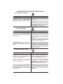
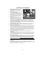
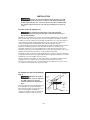
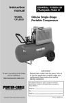
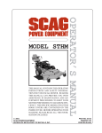
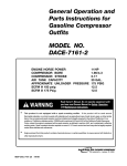
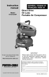
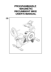
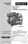
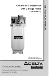
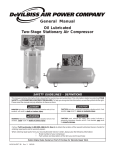
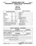
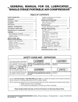
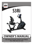
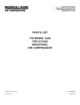
ESPAÑOL: PÁGINA 27 FRANÇAIS: PAGE 53 Instruction manual Single-Stage Oillube Compressor MODEL CPLC7060V To learn more about Porter-Cable visit our website at: http://www.porter-cable.com IMPORTANT Please make certain that the person who is to use this equipment carefully reads and understands these instructions before starting operations. The Model and Serial No. plate is located on the frame. Record these numbers in the spaces below and retain for future reference. Model No. PROFESSIONAL POWER TOOLS Type Serial No. Copyright © 2000 PORTER-CABLE Corporation Part No. D20324-011-2 SAFETY GUIDELINES - DEFINITIONS This manual contains information that is important for you to know and understand. This information relates to protecting YOUR SAFETY and PREVENTING EQUIPMENT PROBLEMS. To help you recognize this information, we use the symbols below. Please read the manual and pay attention to these sections. DANGER indicates an imminently hazardous situation which, if not avoided, will result in death or serious injury. CAUTION indicates a potentially hazardous situation which, if not avoided, may result in minor or moderate injury. WARNING indicates a potentially hazardous situation which, if not avoided, could result in death or serious injury. CAUTION used without the safety alert symbol indicates a potentially hazardous situation which, if not avoided, may result in property damage. Call our Toll Free Number 1-888-559-8550, to obtain the location of the nearest Authorized Service Center for ordering repair parts and for warranty repairs. When ordering repair parts from your local Authorized Service Center, always give the following information: • Model number of your compressor • Part number and description of the item you wish to purchase Retain Original Sales Receipt as Proof of Purchase for Warranty Repair Work. IMPORTANT SAFETY INSTRUCTIONS When using electric tools, basic safety precautions should always be followed to reduce the risk of fire, electric shock and personal injury, including the following: READ AND FOLLOW ALL INSTRUCTIONS. This tool was designed for certain applications. Porter-Cable strongly recommends that this tool NOT be modified and/or used for any application other than for which it was designed. If you have any questions relative to its application, DO NOT use the tool until you have written Porter-Cable and we have advised you. Technical Service Manager Porter-Cable Corporation 4825 Highway 45 North P.O. Box 2468 Jackson, TN 38302-2468 2-ENG IMPORTANT SAFETY INSTRUCTIONS (cont’d) SAVE THESE INSTRUCTIONS IMPROPER OPERATION OR MAINTENANCE OF THIS PRODUCT COULD RESULT IN SERIOUS INJURY AND PROPERTY DAMAGE. READ AND UNDERSTAND ALL WARNINGS AND OPERATING INSTRUCTIONS BEFORE USING THIS EQUIPMENT. HAZARD RISK OF EXPLOSION OR FIRE WHAT CAN HAPPEN HOW TO PREVENT IT IT IS NORMAL FOR ELECTRICAL CONTACTS WITHIN THE MOTOR AND PRESSURE SWITCH TO SPARK. ALWAYS OPERATE THE COMPRESSOR IN A WELL VENTILATED AREA FREE OF COMBUSTIBLE MATERIALS, GASOLINE OR SOLVENT VAPORS. IF ELECTRICAL SPARKS FROM COMPRESSOR COME INTO CONTACT WITH FLAMMABLE VAPORS, THEY MAY IGNITE, CAUSING FIRE OR EXPLOSION. IF SPRAYING FLAMMABLE MATERIALS, LOCATE COMPRESSOR AT LEAST 20 FEET AWAY FROM SPRAY AREA. AN ADDITIONAL LENGTH OF HOSE MAY BE REQUIRED. STORE FLAMMABLE MATERIALS IN A SECURE LOCATION AWAY FROM COMPRESSOR. RESTRICTING ANY OF THE COMPRESSOR VENTILATION OPENINGS WILL CAUSE SERIOUS OVERHEATING AND COULD CAUSE FIRE. NEVER PLACE OBJECTS AGAINST OR ON TOP OF COMPRESSOR. OPERATE COMPRESSOR IN AN OPEN AREA AT LEAST 12 INCHES AWAY FROM ANY WALL OR OBSTRUCTION THAT WOULD RESTRICT THE FLOW OF FRESH AIR TO THE VENTILATION OPENINGS. OPERATE COMPRESSOR IN A CLEAN, DRY, WELL VENTILATED AREA. DO NOT OPERATE UNIT INDOORS OR IN ANY CONFINED AREA. UNATTENDED OPERATION OF THIS PRODUCT COULD RESULT IN PERSONAL INJURY OR PROPERTY DAMAGE. ALWAYS REMAIN IN ATTENDANCE WITH THE PRODUCT WHEN IT IS OPERATING. RISK OF BURSTING AIR TANK: THE FOLLOWING CONDITIONS COULD LEAD TO A WEAKENING OF THE TANK, AND RESULT IN A VIOLENT TANK EXPLOSION AND COULD CAUSE PROPERTY DAMAGE OR SERIOUS INJURY. WHAT CAN HAPPEN 1. 2. 3. 4. FAILURE TO PROPERLY DRAIN CONDENSED WATER FROM THE TANK, CAUSING RUST AND THINNING OF THE STEEL TANK. MODIFICATIONS OR ATTEMPTED REPAIRS TO THE TANK. UNAUTHORIZED MODIFICATIONS TO THE UNLOADER VALVE, SAFETY VALVE, OR ANY OTHER COMPONENTS WHICH CONTROL TANK PRESSURE. EXCESSIVE VIBRATION CAN WEAKEN THE AIR TANK AND CAUSE RUPTURE OR EXPLOSION. ATTACHMENTS & ACCESSORIES: EXCEEDING THE PRESSURE RATING OF AIR TOOLS, SPRAY GUNS, AIR OPERATED ACCESSORIES, TIRES AND OTHER INFLATABLES CAN CAUSE THEM TO EXPLODE OR FLY APART, AND COULD RESULT IN SERIOUS INJURY. HOW TO PREVENT IT DRAIN TANK DAILY OR AFTER EACH USE. IF TANK DEVELOPS A LEAK, REPLACE IT IMMEDIATELY WITH A NEW TANK OR REPLACE THE ENTIRE COMPRESSOR. NEVER DRILL INTO, WELD, OR MAKE ANY MODIFICATIONS TO THE TANK OR ITS ATTACHMENTS. THE TANK IS DESIGNED TO WITHSTAND SPECIFIC OPERATING PRESSURES. NEVER MAKE ADJUSTMENTS OR PARTS SUBSTITUTIONS TO ALTER THE FACTORY SET OPERATING PRESSURES. FOR ESSENTIAL CONTROL OF AIR PRESSURE, YOU MUST INSTALL A PRESSURE REGULATOR AND PRESSURE GAUGE TO THE AIR OUTLET OF YOUR COMPRESSOR. FOLLOW THE EQUIPMENT MANUFACTURERS RECOMMENDATION AND NEVER EXCEED THE MAXIMUM ALLOWABLE PRESSURE RATING OF ATTACHMENTS. NEVER USE COMPRESSOR TO INFLATE SMALL LOWPRESSURE OBJECTS SUCH AS CHILDREN’S TOYS, FOOTBALLS, BASKETBALLS. ETC. 3-ENG IMPORTANT SAFETY INSTRUCTIONS (cont’d) RISK FROM FLYING OBJECTS WHAT CAN HAPPEN HOW TO PREVENT IT THE COMPRESSED AIR STREAM CAN CAUSE SOFT TISSUE DAMAGE TO EXPOSED SKIN AND CAN PROPEL DIRT, CHIPS, LOOSE PARTICLES AND SMALL OBJECTS AT HIGH SPEED, RESULTING IN PROPERTY DAMAGE OR PERSONAL INJURY. ALWAYS WEAR ANSI Z87.1 APPROVED SAFETY GLASSES WITH SIDE SHIELDS WHEN USING THE COMPRESSOR. NEVER POINT ANY NOZZLE OR SPRAYER TOWARD ANY PART OF THE BODY OR AT OTHER PEOPLE OR ANIMALS. ALWAYS TURN THE COMPRESSOR OFF AND BLEED PRESSURE FROM THE AIR HOSE AND TANK BEFORE ATTEMPTING MAINTENANCE, ATTACHING TOOLS OR ACCESSORIES. RISK TO BREATHING WHAT CAN HAPPEN HOW TO PREVENT IT THE COMPRESSED AIR FROM YOUR COMPRESSOR IS NOT SAFE FOR BREATHING! THE AIR STREAM MAY CONTAIN CARBON MONOXIDE, TOXIC VAPORS OR SOLID PARTICLES FROM THE TANK. ALWAYS OPERATE AIR COMPRESSOR OUTSIDE IN A CLEAN, WELL VENTILATED AREA. AVOID ENCLOSED AREAS SUCH AS GARAGES, BASEMENTS, STORAGE SHEDS, WHICH LACK A STEADY EXCHANGE OF AIR. KEEP CHILDREN, PETS AND OTHERS AWAY FROM AREA OF OPERATION. NEVER INHALE AIR FROM THE COMPRESSOR EITHER DIRECTLY OR FROM A BREATHING DEVICE CONNECTED TO THE COMPRESSOR. SPRAYED MATERIALS SUCH AS PAINT, PAINT SOLVENTS, PAINT REMOVER, INSECTICIDES, WEED KILLERS, CONTAIN HARMFUL VAPORS AND POISONS. WORK IN AN AREA WITH GOOD CROSSVENTILATION. READ AND FOLLOW THE SAFETY INSTRUCTIONS PROVIDED ON THE LABEL OR SAFETY DATA SHEETS FOR THE MATERIAL YOU ARE SPRAYING. USE A NIOSH/MSHA APPROVED RESPIRATOR DESIGNED FOR USE WITH YOUR SPECIFIC APPLICATION. RISK OF ELECTRICAL SHOCK WHAT CAN HAPPEN HOW TO PREVENT IT YOUR AIR COMPRESSOR IS POWERED BY ELECTRICITY. LIKE ANY OTHER ELECTRICALLY POWERED DEVICE, IF IT IS NOT USED PROPERLY IT MAY CAUSE ELECTRIC SHOCK. NEVER OPERATE THE COMPRESSOR OUTDOORS WHEN IT IS RAINING OR IN WET CONDITIONS. NEVER OPERATE COMPRESSOR WITH COVER COMPONENTS REMOVED OR DAMAGED. REPAIRS ATTEMPTED BY UNQUALIFIED PERSONNEL CAN RESULT IN SERIOUS INJURY OR DEATH BY ELECTROCUTION. ANY ELECTRICAL WIRING OR REPAIRS REQUIRED ON THIS PRODUCT SHOULD BE PERFORMED BY AUTHORIZED SERVICE CENTER PERSONNEL IN ACCORDANCE WITH NATIONAL AND LOCAL ELECTRICAL CODES. ELECTRICAL GROUNDING: FAILURE TO PROVIDE ADEQUATE GROUNDING TO THIS PRODUCT COULD RESULT IN SERIOUS INJURY OR DEATH FROM ELECTROCUTION. SEE GROUNDING INSTRUCTIONS. MAKE CERTAIN THAT THE ELECTRICAL CIRCUIT TO WHICH THE COMPRESSOR IS CONNECTED PROVIDES PROPER ELECTRICAL GROUNDING, CORRECT VOLTAGE AND ADEQUATE FUSE PROTECTION. 4-ENG IMPORTANT SAFETY INSTRUCTIONS (cont’d) RISK FROM MOVING PARTS WHAT CAN HAPPEN HOW TO PREVENT IT MOVING PARTS SUCH AS THE PULLEY, FLYWHEEL, AND BELT CAN CAUSE SERIOUS INJURY IF THEY COME INTO CONTACT WITH YOU OR YOUR CLOTHING. NEVER OPERATE THE COMPRESSOR WITH GUARDS OR COVERS WHICH ARE DAMAGED OR REMOVED. ATTEMPTING TO OPERATE COMPRESSOR WITH DAMAGED OR MISSING PARTS OR ATTEMPTING TO REPAIR COMPRESSOR WITH PROTECTIVE SHROUDS REMOVED CAN EXPOSE YOU TO MOVING PARTS AND CAN RESULT IN SERIOUS INJURY. ANY REPAIRS REQUIRED ON THIS PRODUCT SHOULD BE PERFORMED BY AUTHORIZED SERVICE CENTER PERSONNEL. RISK OF BURNS WHAT CAN HAPPEN HOW TO PREVENT IT TOUCHING EXPOSED METAL SUCH AS THE COMPRESSOR HEAD OR OUTLET TUBES, CAN RESULT IN SERIOUS BURNS. NEVER TOUCH ANY EXPOSED METAL PARTS ON COMPRESSOR DURING OR IMMEDIATELY AFTER OPERATION. COMPRESSOR WILL REMAIN HOT FOR SEVERAL MINUTES AFTER OPERATION. DO NOT REACH AROUND PROTECTIVE SHROUDS OR ATTEMPT MAINTENANCE UNTIL UNIT HAS BEEN ALLOWED TO COOL. RISK OF FALLING WHAT CAN HAPPEN HOW TO PREVENT IT A PORTABLE COMPRESSOR CAN FALL FROM A TABLE, WORKBENCH OR ROOF CAUSING DAMAGE TO THE COMPRESSOR AND COULD RESULT IN SERIOUS INJURY OR DEATH TO THE OPERATOR OR BYSTANDERS. ALWAYS OPERATE COMPRESSOR IN A STABLE SECURE POSITION TO PREVENT ACCIDENTAL MOVEMENT OF THE UNIT. NEVER OPERATE COMPRESSOR ON A ROOF OR OTHER ELEVATED POSITION. USE ADDITIONAL AIR HOSE TO REACH HIGH LOCATIONS. RISK OF PROPERTY DAMAGE WHEN TRANSPORTING COMPRESSOR (Fire, Inhalation, Damage to Vehicle Surfaces) WHAT CAN HAPPEN OIL CAN LEAK OR SPILL AND COULD RESULT IN FIRE OR BREATHING HAZARD, SERIOUS INJURY OR DEATH CAN RESULT. OIL LEAKS WILL DAMAGE CARPET, PAINT OR OTHER SURFACES IN VEHICLES OR TRAILERS. HOW TO PREVENT IT ALWAYS PLACE COMPRESSOR ON A PROTECTIVE MAT WHEN TRANSPORTING TO PROTECT AGAINST DAMAGE TO VEHICLE FROM LEAKS. REMOVE COMPRESSOR FROM VEHICLE IMMEDIATELY UPON ARRIVAL AT YOUR DESTINATION. ESW-99 9/26/99 5-ENG GLOSSARY CFM: Cubic feet per minute. SCFM: Standard cubic feet per minute; a unit of measure of air delivery. PSIG: Pounds per square inch gauge; a unit of measure of pressure. ASME: American Society of Mechanical Engineers; made, tested, inspected and registered to meet the standards of the ASME. Code Certification: Products that bear one or more of the following marks: UL, CUL, ETL, CETL, have been evaluated by OSHA certified independent safety laboratories and meet the applicable Underwriters Laboratories Standards for Safety. California Code: Unit may comply with California Code 462 (l) (2). Specification/ Model Label is on the side of the air tank on units that comply with California Code. Cut-In Pressure: While the motor is off, air tank pressure drops as you continue to use your accessory. When the air tank pressure drops to a certain low level the motor will restart automatically. The low pressure at which the motor automatically re-starts is called “cut-in pressure.” Cut-Out Pressure: When you turn on your air compressor and it begins to run, air pressure in the air tank begins to build. It builds to a certain high pressure before the motor automatically shuts off - protecting your air tank from pressure higher than its capacity. The high pressure at which the motor shuts off is called "cut-out pressure." To Lock Out Power: Place a lock on the line power switch so no one else can turn on the power. DUTY CYCLE Porter-Cable air compressors should be operated on not more than a 50% duty cycle. This means an air compressor that pumps air more than 50% of one hour is considered misuse, because the air compressor is undersized for the required air demand. Maximum compressor pumping time per hour is 30 minutes. SPECIFICATIONS Model No. Horsepower Peak Voltage/Hertz/Phase Minimum Branch Circuit Requirement * Fuse Type Air Tank Capacity (Gallon) Approximate Cut-in Pressure Approximate Cut-out Pressure SCFM @ 40 PSIG SCFM @ 90 PSIG CPLC7060V 7.0 240V/60 Hz/ 1 Ph 15 Amp Time Delay-Type D 60 ASME, Vertical 110 PSIG 135 PSIG 12.1 9.7 * 1. 2. 3. 4. This air compressor can be operated on a 15 amp circuit if: Voltage supply to circuit is normal. Circuit is not used to supply any other electrical needs (lights, appliances, etc.) Extension cords comply with specifications in owners manual. Circuit is equipped with 15 amp circuit breaker or 15 amp time delay fuse marked Type D. If any of the above conditions cannot be met, or if operation of the air compressor repeatedly causes interruption of the power it may be necessary to operate it from a 20 amp circuit. It is not necessary to change the cord set. * A circuit breaker is preferred. Use only a fuse or circuit breaker that is the same rating as the branch circuit on which the air compressor is operated. If the air compressor is connected to a circuit protected by fuses, use dual element time delay fuses. 6-ENG DESCRIPTION OF OPERATION ON/AUTO-OFF Switch (A) Fig. 1: Turn B this switch ON to provide automatic power to the pressure switch and OFF to A remove power. Pressure Switch (B) Fig. 1: The pressure switch automatically starts the E motor when the air tank pressure drops below the factory set "cut-in" pressure. It stops the motor when the air tank pressure reaches the factory set "cutD C out" pressure. Air Tank Safety Valve (C) Fig. 1: If the pressure switch does not shut off the air Fig. 1 compressor at its cut-out pressure setting, the safety valve will protect against high pressure by "popping off" at its factory set pressure (slightly higher than the pressure switch cut-out setting). Air Tank Pressure Gauge (D) Fig. 1: The air tank pressure gauge indicates the reserve air pressure in the air tank. On units with no pressure regulator, this is also the pressure available at the air outlet. Air Intake Filter (not shown): This filter is designed to clean air coming into the pump. This filter must always be clean and ventilation openings free from obstructions. See "Maintenance". Air Compressor Pump (not shown): To compress air, the pistons moves up and down in the cylinder. On the downstroke, air is drawn in through the air intake valves. The exhaust valve remains closed. On the upstroke of the piston, air is compressed. The intake valves close and compressed air is forced out through the exhaust valve, through the outlet tube, through the check valve and into the air tank. Working air is not available until the compressor has raised the air tank pressure above that required at the air outlet. Drain Valve (not shown): Located at the base of the air tank to drain condensation. Check Valve (not shown): When the air compressor is operating, the check valve is "open", allowing compressed air to enter the air tank. When the air compressor reaches "cut-out" pressure, the check valve "closes", allowing air pressure to remain inside the air tank. Pressure Release Valve (not shown): The pressure release valve, located on the side of the pressure switch, is designed to automatically release compressed air from the compressor head and the outlet tube when the air compressor reaches "cut-out" pressure or is shut off. The pressure release valve allows the motor to restart freely. When the motor stops running, air will be heard escaping from the valve for a few seconds. No air should be heard leaking when the motor is running. Shut-off Valve (sold separately): Closes the air outlet (E, Fig. 1) allowing the tank to fill with air. Regulator (sold separately): An air pressure regulator or a separate air transformer which combines the functions of air regulation and/or moisture and dirt removal is recommended for most applications. 7-ENG INSTALLATION Improper electrical installation of this product may void its warranty and your fire insurance. Have circuit wiring performed by qualified personnel such as a licensed electricians who is familiar with the current national electrical code and any prevailing local electrical codes. Location of the Air Compressor The manifold assembly does not provide adequate stability or support for lifting the unit. If the unit must be moved, use the air tank for lifting. Operate the air compressor in a clean, dry, and well-ventilated area. The air intake filter must be kept clear of obstructions which could reduce air delivery of the air compressor. The air compressor should be located at least 12" away from walls or other obstructions that could interfere with the flow of air. The air compressor crankcase and head are designed with fins to provide proper cooling. The flywheel side of the unit should be placed toward the wall and protected with a totally enclosed belt guard. The area should allow space on all sides for air circulation and for ease of normal maintenance. Keep the unit away from areas which have dirt, vapor, and combustible fumes in the atmosphere which may clog and gum the intake filter and valves, causing inefficient operation. If humidity is high, an air filter can be installed in line to remove excessive moisture. Closely follow instructions packaged with the filter for proper installation. It must be installed as close as possible to the accessory. The air compressor should be as near to air outlets as possible in order to avoid long pipe lines. Do not place the air compressor where heat is excessive. Do not use an extension cord. To avoid voltage drop and power loss to the motor, use extra air hose instead of an extension cord. Air Compressor Anchoring Methods (Fig. 2) Vibration can weaken the air tank and cause an explosion. The AIR compressor must be properly mounted as illustrated in Fig 2. This air compressor must be bolted to the floor. Bolting holes are provided in the base feet. Mount the air compressor on a solid, level foundation. Support air compressor weight evenly on all four feet. Solid shims may be used if necessary. 3/8" Lag Screw (not supplied) Torque to 5-7 Ft.Lb. 3/8" Flat Washer (not supplied) Isolator Washer 8-ENG Floor Line Shim Under Isolator Washer if Necessary (not supplied) Lag Screw Anchor for Concrete (not supplied) Fig. 2 Wiring Instructions (Fig. 3) Perform electrical wiring according to the following instructions: Improper electrical grounding can result in a risk of electrical shock. Wiring for the pressure switch AND electrical motor should be done by a licensed electrician in accordance with national and local codes and ordinances. Install the air compressor unit as close to the main power supply as possible. This practice will avoid using long lengths of electrical wiring for the power supply which can cause power loss to the motor. When connecting wires make sure that: 1. The amperage rating of the electrical box is adequate. 2. The supply line has the same electrical characteristics (voltage, cycle, and phase) as motor. Refer to the Specification Chart or your air compressor unit. NOTE: THESE UNITS DO NOT INCLUDE ANY WIRING BECAUSE OF VARIOUS INSTALLATION REQUIREMENTS. Wiring must be such that full motor nameplate voltage plus or minus 10% is available at the motor terminals during starting. Refer to local codes for recommended wire sizes for correct wire size and maximum wire run; undersize wire causes high amp draw and Typical Wiring Of Air compressor Units overheating to the motor. with 60 Gallons Capacity Electrical wiring must be located away from hot surfaces such as the air compressor head, compressor cylinder, or compressor outlet tube. Fig. 3 9-ENG Voltage and Circuit Protection Refer to the Specifications for the voltage and circuit protection requirements of your air compressor. Use only a fuse or circuit breaker that is the same rating as the branch circuit on which the air compressor is operated. If the air compressor is connected to a circuit protected by fuses, use only dual element time delay fuses, as noted in the Specifications. Typical schematic subject to all changes as dictated by local electrical codes and authorities. This product should be connected to a grounded, metallic, permanent wiring system, or an equipment-grounding terminal or lead on the product. Fig. 4 GROUNDING INSTRUCTIONS RISK OF ELECTRICAL SHOCK! In the event of a short circuit, grounding reduces the risk of shock by providing an escape wire for the electric current. This air compressor must be properly grounded. Improper grounding can result in electrical shock! All grounding should be performed by a licensed electrician in accordance with national and local electrical codes! Make certain that the electrical circuit to which the air compressor is connected provides proper electrical grounding, correct voltage and adequate fuse protection. The air compressor can be grounded by the following method: When hard wiring an air compressor, use wiring that contains a bare copper grounding wire. This wire must be connected to the pressure switch at the grounding location provided. This is located inside the pressure switch. The other end of the wire must be connected to a ground at the fuse/circuit breaker box in accordance with national and local electrical codes. If these grounding instructions are not completely understood, or if you are in doubt as to whether the air compressor is properly grounded, have the installation checked by an Authorized Warranty Service Center or a licensed electrician. Lubrication and Oil Air compressors are shipped without oil. A small amount of oil may be present in the pump upon receipt of the air compressor. This is due to plant testing and does not mean that the pump contains the correct amount of oil. Do not attempt to operate in order to check wiring or for any reason without first adding oil to the crankcase. Serious damage to the pump can result from even very limited use without oil. Fill crankcase with recommended oil before operating. Multi-viscosity motor oils like 10W30, should not be used in an air compressor. They leave carbon deposits on critical components, thus reducing performance and air compressor life. Use air compressor oil only. 10-ENG 1. Refer to the Service Instructions in this manual for the specific oil recommended for use in your air compressor unit. 2. Remove the oil fill plug. 3. Fill the crankcase. The oil level should be even with the top of the fill hole and must not be allowed to be lower than 3/8" from the top (6 threads) at any time. 4. Replace the oil fill plug and tighten securely. Additional Regulators and Controls Since the air tank pressure is usually greater than that which is needed, a separate regulator is usually employed to control the air pressure ahead of any individual air driven device. Separate air transformers that combine the functions of air regulation and moisture and dirt removal should be used where applicable. Piping Plastic or PVC pipe is not designed for use with compressed air. Regardless of its indicated pressure rating, plastic pipe can burst from air pressure. Use only metal pipe for air distribution lines. Note The shut-off valve is not supplied with this unit. You must purchase the shut-off valve separately. Note Where a remote air intake is used, enlarge the size of the air intake piping by one pipe size for each 10 feet of length. A typical compressed air distribution system as shown in fig. 5 should be of sufficient pipe size to keep the pressure drop between the supply and point of use to a minimum. All pipes and fittings used must be certified safe for the pressures involved. Pipe thread lubricant must be used on all male pipe threads, and all joints are to be made up tight, since small leaks in the piping system are the largest single cause of high operating costs. All piping should be sloped to an accessible drain point and all outlets should be taken from the top of the main distribution air line so that moisture cannot enter the outlet. The main distribution air line should not be smaller than the air compressor discharge valve outlet. A smaller line will restrict the flow of air. If piping is over 100 feet long, or if required air flow will exceed 15 SCFM, use 3/4" scheduled 40 piping. Note For underground installation, bury air lines below the frost line and avoid pockets where condensation can gather and freeze. Apply pressure before underground lines are covered to make sure all pipe joints are free from leaks. A flexible coupling needs to be installed between the shut-off valve (sold separately) and the main air distribution line to allow for vibration. To remove dirt, oil, and water, install a separator in the main distribution line. Install separator 5 to 6 feet from air compressor to allow the air to cool to room temperature before passing through the separator. Additional separators or filters may be used depending on the application. Water occurs naturally in air lines as a result of compression. Moisture vapor in ambient air is concentrated when pressurized and condenses when cooled in downstream air piping. 11-ENG Compressed air dryers reduce the water vapor concentration and prevent water formation in compressed air lines. Dryers are a necessary companion to filters, aftercoolers, and automatic drains for improving the productivity of compressed air systems. Water and water vapor removal increases the efficiency of air operated equipment, reduces contamination and rusting, increases the service life of pneumatic equipment and tools, prevents air line freeze-ups, and reduces product rejects. The use of dryers, aftercoolers, and filters is recommended when these moisture related problems are reported to our factory or distributor service department. Typical Compressed Air Distribution System Fig. 5 12-ENG BREAK-IN PROCEDURES This procedure is required before the air compressor is put into service, before the hose is installed, the check valve is replaced, or a complete compressor pump is replaced. Serious damage may result if the following break-in instructions are not closely followed. The procedure: 1. Make sure the pressure switch lever is in the "OFF" position. 2. Check air compressor wiring. Make sure wires are secure at all terminal connections. Free all contacts of loose wire cuttings, ect. 3. Open the drain valve fully to permit air to escape and prevent air pressure buildup in the air tank during the break-in period. 4. Move the pressure switch lever to "ON/AUTO". The compressor will start. 5. Run the air compressor for 30 minutes. Make sure the drain valve is open and there is minimal air pressure build-up in tank. 6. After 30 minutes move the pressure switch lever to the OFF position, check oil and add if necessary. 7. Close the drain valve. 8. Move the pressure switch lever to "ON/AUTO". The air receiver will fill to cutout pressure and the motor will stop. Your air compressor is now ready for use. OPERATING PROCEDURES Daily Start-Up Checklist 1. Check oil and add if necessary. 2. Before attaching an air hose or accessory, make sure the shut-off valve is in the closed position. Make sure the ON/AUTO lever is in the OFF position. Compressed air from the unit may contain water condensation and oil mist. Do not spray unfiltered air at an item that could be damaged by moisture. Some air operated tools or devices may require filtered air. Read instructions for air tool or device. 3. Attach regulator, hose and accessory. On models without an air pressure regulator, one must be installed before using accessories rated at less than 135 psig. Too much air pressure causes a hazardous risk of bursting. Check the manufacturer's maximum pressure rating for air tools and accessories. The regulator outlet pressure must never exceed the maximum pressure rating. 4. Place the pressure switch lever in the ON-AUTO position. The motor will stop when air tank pressure reaches "cut-out pressure". 5. Open the shut-off valve. 6. If an air pressure regulator is in use, open the regulator by turning it clockwise. Adjust the regulator to the correct pressure setting. Your unit is ready for use. When You Are Finished: 7. Turn the air compressor unit off. 8. Turn the regulator counterclockwise and set the outlet pressure to zero. 9. Remove the air tool or accessory. 13-ENG 10.Open the regulator and allow the air to slowly bleed from the air tank. Close the regulator when air tank pressure is approximately 20 psi. 11.Open the drain valve underneath the air tank and drain water from air tank. DRAIN AIR TANK DAILY. Water will condense in the air tank. If not drained, the water will corrode and weaken the air tank, causing a risk of air tank rupture. The air tank must be drained properly. 12.After the water has been drained, close the drain valve. - if the air compressor is under continuous use, drain at least once each day. - if the air compressor is only used occasionally, drain after each use. Note If drain cock valve is clogged, release air pressure in air tank. The drain cock valve can then be removed, cleaned and reinstalled. MAINTENANCE Unit cycles automatically when power is on. During maintenance, you could be exposed to voltage sources, compressed air, moving parts, or hot surfaces. Personal injuries can occur. Unplug the unit and bleed off all air tank pressure and allow unit to cool before doing any maintenance or repair. Never operate the unit with the belt guard removed. To ensure efficient operation and longer life of the air compressor unit, a routine maintenance schedule should be prepared and followed. The following routine maintenance schedule is geared to a unit in a normal working environment operating on a daily basis. If necessary, the schedule should be modified to suit the conditions under which your air compressor is used. The modifications will depend upon the hours of operation and the working environment. Air compressor units in an extremely dirty and/or hostile environment will require a greater frequency of all maintenance checks. Routine Maintenance Schedule Daily: 1. Check oil level. Add if necessary. 2. 3. 4. 5. 6. 7. 8. Overfilling with oil will cause premature air compressor pump failure. Do not overfill. Open the shut-off valve. Open the regulator and allow the air to slowly bleed from the air tank. Close the regulator when air tank pressure is approximately 20 psi. Drain water from the air tank, any moisture separators, or transformers. Check for any unusual noise and/or vibration. Manually check all safety valves to make sure they are operating properly. Inspect for oil leaks. Take unit to an Authorized Service Center for repair. Inspect air filter and replace if necessary. Every 40 Hours of Operation: 1. Inspect condition of drive belt; replace if necessary. Every 100 Hours of Operation: 1. Drain and refill compressor crankcase with 16 fluid ounces (473.2 ml) of clean compressor oil. 2. Increase frequency of oil changes if humidity or operating conditions are extreme. 14-ENG Every 160 Hours of Operation: 1. Check drive belt tension; adjust if necessary. 2. Inspect air lines and fittings for leaks; correct as necessary. 3. Check the alignment of the motor pulley to the flywheel. If necessary, align to within 1/32 inch on center line. Each Year of Operation or if a Problem is Suspected: Check condition of air compressor pump intake and exhaust valves. Replace if damaged or worn out. SERVICE INSTRUCTIONS Air Filter - Inspection and Replacement NOTE Keep the air filter clean at all times. Do not operate the air compressor with the air filter removed. A dirty air filter will not allow the air compressor to operate at full capacity. Before you use the air compressor, check the air filter to be sure it is clean. If it is dirty, replace it with a new filter. Oil - Checking and Changing 1. 2. 3. 4. 5. 6. Overfilling with oil will cause premature air compressor pump failure. Do not overfill. Check oil level in air compressor crankcase before each use. The oil level should be even with the top of the fill hole and must not be allowed to be lower than 3/8" from the top (6 threads) at any time. See Routine Maintenance Schedule for oil change scheduling. Remove the oil fill and drain plugs. Collect the oil in a suitable container. Replace the oil drain plug and refill the crankcase with recommended oil. Note It is important to maintain the proper oil level. A low oil level reduces proper cylinder wall lubrication and increases ring wear. Replace the oil fill plug. Start the air compressor unit and run for several minutes. Shut the air compressor down and check the oil level. If necessary, add more oil. Viscosity Chart Recommended Oil (API SG/CD Heavy Duty)* SAE 10 SAE 20 Room or Ambient Temperature Below 20oF Above 32oF Oil Type An air compressor grade non-detergent oil should be used. Most automotive detergent oils cause excessive carbon buildup and should not be used. Do not use synthetic oil for the first 300 hours. All units should be broken in on petroleum based oil. Oil Capacity Oil capacity is approximately 16 fluid ounces. The oil level should be even with the top of the fill hole and must not be allowed to be lower than 3/8" from the top (6 threads) at any time. 15-ENG Check Valve - Inspection and Replacement Remove and inspect the check valve at least once a year or more often if the air compressor is heavily used. Moisture and other contaminants in the hot compressed air will cause an accumulation of a carbon-like residue on the working parts. If the valve has heavy carbon build-up, it should be replaced. Use the following procedure to inspect, clean or replace the check valve. 1. Turn air compressor off and disconnect or lock out power source. 2. Release air pressure from the air tank. 3. Loosen the top and bottom tube nuts and remove the outlet tube. 4. Remove pressure release tube. 5. Unscrew the check valve. 6. Check that the valve disc moves freely and that the spring holds the disc in the upper, closed position. The check valve may be cleaned with a solvent. 7. Apply sealant to the check valve threads. Reinstall the check valve. Do not overtighten. 8. Replace the outlet tube and tighten top and bottom nuts. 9. Replace pressure release tube. 10. Perform the Break-in procedure. Safety Valve - Inspection and Replacement (Fig. 6) IF THE SAFETY VALVE DOES NOT WORK PROPERLY, OVER-PRESSURIZATION MAY OCCUR CAUSING AIR TANK RUPTURE OR EXPLOSION. OCCASIONALLY PULL THE RING ON THE SAFETY VALVE TO MAKE SURE THAT THE SAFETY VALVE OPERATES FREELY. IF THE VALVE IS STUCK OR DOES NOT OPERATE SMOOTHLY, IT MUST BE REPLACED WITH A VALVE HAVING THE SAME PRESSURE RATING. 1. Remove and lock out power from the air compressor. Release any air pressure from the air tank. 2. Remove safety valve and replace with valve of the same pressure rating. 3. Apply thread sealant to new safety valve and tighten. DO NOT OVERTIGHTEN. SAFETY VALVE Fig. 6 Belt - Replacement SERIOUS INJURY OR DAMAGE MAY OCCUR IF PARTS OF THE BODY OR LOOSE ITEMS GET CAUGHT IN MOVING PARTS. NEVER OPERATE THE UNIT WITH THE BELT GUARD REMOVED. THE BELT GUARD SHOULD BE REMOVED ONLY WHEN THE AIR COMPRESSOR POWER IS DISCONNECTED. 1. Remove and lock out power from the compressor. 2. Remove beltguard screws and beltguard. 3. Remove belt and replace. 16-ENG NOTE The belt must be centered over the grooves on the flywheel and motor pulley. 4. To reinstall beltguard, align the bottom tabs of the beltguard into the slots of the base. These are located behind the ON/OFF switch. Replace beltguard screws and tighten securely. Belt Guard - Removal and Installation 1. Remove and lock out power from the compressor. Release any air pressure from the air tank. 2. Move the “ON/AUTO-OFF” lever to the “OFF” position. Remove and lock out power from the compressor. Release all air tank pressure. 3. Remove the beltguard screws and remove beltguard. 4. To reinstall beltguard, align the bottom tabs of the beltguard into the slots of the base. These are located behind the ON/OFF switch. Replace beltguard screws and tighten securely. Adjusting Belt Tension 1. Remove and lock out power from the compressor. Release any air pressure from the air tank. 2. Loosen the four screws from the beltguard. Remove beltguard. 3. Remove belt. 4. Loosen motor mounting bolts and slide motor to achieve correct belt tension. 5. Tighten motor mount bolts to 10-20 ft./lbs. and replace belt. 6. Check for proper tension by applying three pounds of pressure midway between the motor pulley and the beltwheel. The belt is properly tensioned when it deflects approximately 1/4" at this point. 7. Ensure beltwheel and motor pulley are aligned. 8. Replace beltguard. Pressure Switch - Replacement PRESSURE LOADS BEYOND DESIGN LIMITS MAY CAUSE TANK RUPTURE OR EXPLOSION. PRESSURE SWITCH OPERATION IS RELATED TO MOTOR HP, TANK RATING, AND SAFETY VALVE SETTING. DO NOT ATTEMPT TO ADJUST, REMOVE OR DEFEAT THE PRESSURE SWITCH, OR CHANGE AND MODIFY ANY PRESSURE CONTROL RELATED DEVICE. A PRESSURE SWITCH OF THE SAME RATING MUST BE USED WHEN REPLACEMENT IS NECCESSARY. CONTACT AN AUTHORIZED SERVICE CENTER FOR REPLACEMENT. Motor Overload Protector - Reset The motor has a manual thermal overload protector. If the motor overheats for any reason, the overload protector will shut off the motor. The motor must be allowed to cool down before restarting. Turn the unit off. To restart, depress the red reset button located on the end of the motor and turn the ON/AUTO-OFF switch to the ON position. Pulley and Flywheel - Alignment The compressor flywheel and motor pulley grooves must be aligned within 1/32”. To check alignment: 1. Remove and lock out power from the compressor. 17-ENG 2. Remove beltguard. 3. Place a straight edge (such as a ruler) against the outside of the flywheel and measure the distance from it to the nearest groove. Alignment is achieved when the other end of the straight edge is within 1/32” of the measured dimension at the pulley grooves. If the pulleys are not aligned: a. Loosen the motor pulley set screw. b. Slide pulley until alignment is achieved. c. Tighten pulley set screw to 70-80 inch pounds. 4. Replace beltguard and tighten beltguard screws securely. Servicing Intake and Exhaust Valves 1. Remove and lock out power from compressor and relieve all air pressure from the air tank. 2. Remove belt guard as noted in "Belt Guard - Removal and Installation" in this manual. 3. Remove the air filter assembly. 4. Disconnect the pressure release and outlet tubes from the air compressor. 5. Remove the hardware securing the cylinder head and remove the cylinder head and valve plate. MANY SOLVENTS ARE HIGHLY FLAMMABLE AND A HEALTH HAZARD IF INHALED. ALWAYS OBSERVE THE SOLVENT MANUFACTURER'S SAFETY INSTRUCTIONS AND WARNINGS. 6. Clean carbon deposits in head cavities and valve plates with lacquer thinner or other suitable solvent. 7. Clean the intake and exhaust valves with lacquer thinner or other suitable solvent. Inspect valves; replace if necessary. NOTE Do not use gasket cement on any gasket surface as this may clog compressor valve cavities and air flow areas. 8. Reinstall valve plate and gaskets. 9. Install the cylinder head. Snug mounting screws and studs tight, then torque to 25 to 30 foot pounds starting at the center and working toward the outside. 10.Reconnect the pressure release and outlet tubes to the compressor pump. 11.Replace air filter assembly. 18-ENG STORAGE OF COMPRESSOR UNIT 1. Review the Maintenance section on the preceding pages and perform scheduled maintenance as necessary. 2. Turn the air compressor unit off. 3. Turn the regulator counterclockwise and set the outlet pressure to zero. 4. Remove the air tool or accessory. 5. Open the regulator or and allow the air to slowly bleed from the air tank. Close the regulator when air tank pressure is approximately 20 psi. 6. Open the drain valve underneath the air tank and drain water from air tank. DRAIN AIR TANK DAILY. Water will condense in the air tank. If not drained, the water will corrode and weaken the air tank, causing a risk of air tank rupture. The Air tank must be drained properly. 7. After the water has been drained, close the drain valve. Note If drain cock valve is clogged, release air pressure in air tank. The drain cock valve can then be removed, cleaned and reinstalled. 8. Protect the electrical cord and/or air hose from damage (such as being stepped on or run over). 9. Store the air compressor in a clean and dry location. 19-ENG TROUBLESHOOTING GUIDE PERFORMING REPAIRS MAY EXPOSE VOLTAGE SOURCES, MOVING PARTS OR COMPRESSED AIR SOURCES. PERSONAL INJURY MAY OCCUR. PRIOR TO ATTEMPTING ANY REPAIRS, UNPLUG THE AIR COMPRESSOR AND BLEED OFF ALL AIR TANK AIR PRESSURE. CAUSE CORRECTION PROBLEM Excessive air tank pressure - safety valve pops off (units with ON-AUTO switch). Pressure switch does not shut off motor when air compressor reaches “cut-out” pressure. Move the pressure switch lever to the “OFF” position. If the unit doesn’t shut off, and the electrical contacts are welded together, replace the pressure switch. Pressure switch “cut-out” too high. Pressure switch does not shut off motor when air compressor reaches "cut-out pressure". Contact a Service Center to check and adjust, or replace switch. Pressure switch must be replaced. Tube fittings are not tight enough. Tighten fittings where air can be heard escaping. Check fittings with soapy water solution. DO NOT OVER-TIGHTEN. Air leaks at or inside check valve. Malfunctioning or dirty check valve. A malfunctioning check valve results in a constant air leak at the pressure release valve when pressure is in the air tank and the air compressor is shut off. Remove and clean or replace check valve. DO NOT OVER-TIGHTEN. Air leaks at pressure switch release valve during running. Malfunctioning pressure switch release valve. Remove and replace the release valve. Continuous air relieving from pressure switch release valve after shut off. Malfunctioning check valve. Replace check valve. Air leaks in air tank or at air tank welds. Damaged air tank. Air tank must be replaced. Air leak from safety valves. Possible malfunctioning in safety valve. Operate safety valve manually by pulling on ring. If a valve still leaks, it should be replaced. Squealing sound. Loose belt. Adjust belt tension. (See Belt Replacement.) No oil in the air compressor pump. Add oil. Excessive air tank pressure - safety valve pops off (units without ON-AUTO switch). Air leaks at fittings or hose. . DO NOT DRILL INTO, WELD, OR OTHERWISE MODIFY AIR TANK. IT WILL WEAKEN. THE AIR TANK CAN RUPTURE OR EXPLODE. 20-ENG PROBLEM CAUSE CORRECTION Motor will not run. Motor overload protection switch has tripped. Let motor cool off and reset switch by pressing the red button located on the end of the motor. If the overload still trips, check for malfunctioning capacitor or wrong voltage. Air tank pressure exceeds pressure switch "cut-in pressure". Motor will start automatically when air tank pressure drops below "cutin pressure" of pressure switch. Check valve stuck open. Remove and clean or replace. DO NOT OVERTIGHTEN. Loose electrical connections. Check wiring connection inside pressure switch and motor terminal box area. Possible malfunctioning capacitor. Contact Service Center for inspection or replacement if necessary. Paint spray on internal motor parts. Have checked by a Service Center. Do not operate the air compressor in the spray area. See Flammable Vapor Warning. Possible malfunctioning motor. Have checked by a local Service Center. Fuse blown, circuit breaker tripped. 1. Check fuse box for blown fuse and replace if necessary. Reset circuit breaker. Do not use a fuse or circuit breaker with higher rating than that specified for your particular branch circuit. 2. Check for proper fuse; only dual element time delay fuses are acceptable. Use a time delay fuse. 3. Check for low voltage conditions and/or proper extension cord. 4. Remove check valve and clean or replace if it is stuck open or closed. 5. Disconnect the other electrical appliances from circuit or operate the air compressor on its own branch circuit. On an ON/AUTO pressure switch equipped with a pressure relief valve, bleed the line by pushing the pressure switch to the OFF position. If valve does not open, bend the lever until it does. If valve still fails to bleed, replace the valve assembly. Pressure release valve on pressure switch has not unloaded head pressure. 21-ENG PROBLEM CAUSE CORRECTION Excessive belt wear. Loose belt/tight belt. Loose pulley. Adjust belt tension. (See Belt Replacement.) Check for worn keyway or pulley bore. Also check for bent motor shaft. Replace parts if necessary. (Refer to the Unit Parts Manual.) Air compressor is not supplying enough air to operate accessories. Prolonged excessive use of air. Decrease amount of air usage. Air compressor is not large enough for air requirement. Check the accessory air requirement. If it is higher than the CFM or pressure supplied by your air compressor, you need a larger air compressor. Restricted air intake filter. Clean or replace air intake filter. Do not operate the air compressor in the paint spray area. Loose belt. Adjust belt tension. Hole in hose. Check and replace if required. Check valve restricted. Remove and clean or replace. Air leaks. Tighten fittings. (See "Air Leaks" section of "Troubleshooting Guide".) Malfunctioning check valve. Remove and clean or replace. Loose pulley. Tighten pulley set screw. See Unit Parts Manual for correct torque specifications. Low oil level. Loose flywheel. Maintain prescribed oil level. Loosen air compressor mounting screws. Check screws. Tighten as required. Belt too tight/too loose. Adjust belt tension. (See Belt Replacement.) Carbon build-up. Remove the head and valve plate. Clean the valve plate and the top of the piston. (Be sure carbon does not fall into the cylinder.) Reassemble using new gaskets and see Unit Parts Manual for correct torque specifications. Restricted air intake. Replace the air intake. Air compressor overworked. Reduce air consumption or add another air compressor to take up some of the load. Poor quality oil. Drain pump and replace with correct oil. Refer to Lubrication and Oil Section. Knocking noise. Excessive oil consumption. Tighten screw. See Unit Parts Manual for correct torque specifications. 22-ENG PROBLEM CAUSE CORRECTION Air compressor overheating. Air compressor overworked. Reduce air consumption or add another air compressor to take up some of the load. The outlet tube and/or check valve is restricted. Check the tube and the check valve. Clean if necessary. Dirty air compressor. Clean the air compressor thoroughly. High ambient temperature. Use remote air intake. Incorrect oil, low oil. See oil recommendation on page 15. Low voltage. Provide correct voltage. Consult local power company or electrician. Pressure switch set beyond factory setting. Do not set switch beyond maximum for which unit was designed as noted on nameplate. Belt too tight. Adjust for proper tension. Motor overheating. Clean or replace air compressor Air compressor valves have valves or check valve. excessive carbon deposits build-up; restricted check valve. Too many motor starts per hour. Consult Service Center. Check electrical hookup and Improper wiring gauge. installation data or consult Incorrect voltage. electrician. NOTE Current style electric motors run relatively hot under normal operating conditions, with reasonable air compressor loading. This condition is normal and no adjustment is necessary. Under normal operating conditions, the motor amperage draw will not exceed the nameplate amperage rating, plus the service factor, as it appears on the electric motor. If a condition of sustained high amperage exists, refer to service checks above and/or consult electrician. If cause cannot be isolated by an electrician, consult with Service Center for additional assistance. Water in pump crankcase; oil appears milky in color. Humid operating conditions. Liquid water or moisture in air lines. Condensation forms in air lines when the warm compressed air coming from the air tank starts to cool down as it travels through the air lines. Relocate air compressor unit, or change oil frequently. Consult Service Center. Unit not reaching proper operating temperature because the air compressor runs infrequently and is oversized for the air requirement. 23-ENG Install compressed air dryer sized for the flow and dryness level required. ACCESSORIES Accessories can be found at the store from which the unit was purchased or at a local hardware store. FILTERS, REGULATORS, LUBRICATORS FILTER / REGULATOR REGULATOR Controls air pressure downstream and /or in secondary feeder lines. Regulates air pressure and removes moisture, oil and other debris from the air line. Protects tools from rust and is essential when spray painting. Locate as close to the tool as possible. LUBRICATOR OR INLINE OILER Administers oil into the air line. Reduces excessive wear and rusting in tools. Do not use when spray painting. PLUMBING COMPONENTS CONNECTORS Connects components that have similar NPT threads; Male or Female. SHUT-OFF VALVE ADAPTERS Combines components that have different NPT threads; Male or Female. On/Off valve. Controls air flow; not air pressure. T-FITTING 360 O SWIVEL CONNECTOR Ideal for branching air lines. Eliminates hose twist and improves tool handling. INLINE VALVE On/Off valve. Controls air flow; not air pressure. HOSE 3/8" I.D. HOSE Ideal for increasing working distance in high CFM applications. QUICK-CONNECTS 1/4" COIL HOSE Self-retracting and lightweight. Less bulk than regular hoses. Ideal secondary hose line in lower CFM applications. 24-ENG BODIES & PLUGS Together they provide quick and easy attachment/separation of components within the air line. Do not mix different styles of bodies/plugs. NOTES 25-ENG LIMITED WARRANTY PORTER-CABLE CORPORATION warrants to the original purchaser that each new air compressor and service part is free from defects in material and workmanship and agrees to repair or replace under this warranty any defective product or part as follows from the original date of purchase. 5 YEARS – Limited warranty on 2-stage oil-free air compressor pumps that operate at 1725 RPM and 1 year limited warranty on all other parts. 3 YEARS – Limited warranty on oil-lubricated air compressor pumps and 1 year limited warranty on all other parts. 1 YEAR – Limited warranty on all other air compressor products. 90 Day – Service parts Engine warranties are the responsibility of the engine manufacturer. Warranties of merchandise sold by Porter-Cable which has been manufactured by and identified as the product of another company are the responsibility of the manufacturer of that product. THIS WARRANTY IS NOT TRANSFERABLE AND DOES NOT COVER • Products sold damaged or incomplete, sold “as is”, sold reconditioned or used as rental equipment. • Delivery, installation or normal adjustments explained in the owner’s manual. • Damage or liability caused by shipping, improper handling, improper installation, incorrect voltage or improper wiring, improper maintenance, improper modification, or the use of accessories and/or attachments not specifically recommended by PORTERCABLE for the tool. • Repairs necessary because of operator abuse or negligence, or the failure to install, operate, maintain and store the product according to the instructions in the owner’s manual. • Damage caused by cold, heat, rain, excessive humidity, corrosive environments and materials, or other contaminants. • Expendable items that become worn during normal use such as drain valves, fuses, filters, belts, air cleaners, spark plugs, engine oil and pump oil. • Cosmetic defects that do not interfere with tool functionality. • Freight costs from customer to Porter-Cable. • Repair and transportation costs of products or parts determined not to be defective. • ANY INCIDENTAL, INDIRECT OR CONSEQUENTIAL LOSS, DAMAGE, OR EXPENSE THAT MAY RESULT FROM ANY DEFECT, FAILURE OR MALFUNCTION OF THE PRODUCT. Some states do not allow the exclusion or limitation of incidental or consequential damages, so the above limitation or exclusion may not apply to you. • IMPLIED WARRANTIES, INCLUDING THOSE OF MERCHANTABILITY AND FITNESS FOR A PARTICULAR PURPOSE, ARE LIMITED TO ONE YEAR FROM THE DATE OF ORIGINAL PURCHASE. Some states do not allow limitations on how long an implied warranty lasts, so the above limitations may not apply to you. WARRANTY SERVICE is available by delivering or shipping the defective product or part to any Porter-Cable authorized warranty service location. To determine the nearest authorized warranty service location, call the toll free number, 1-888-559-8550, 24 hours a day, 7 days a week. Specific instructions regarding servicing arrangements and scheduling may vary depending on the type and size of the product and the availability of repair parts. • DO NOT return the defective product to the retailer. • Retain the original cash register sales receipt as proof of purchase for warranty work. • Only Air compressors with 60 and 80 gallon tanks will be inspected at the site of installation. • The customer should contact Porter-Cable directly if the purchaser does not receive satisfactory results from the authorized warranty service center. Porter-Cable Corporation 4825 Highway 45 North P.O. Box 2468 Jackson, TN 38302-2468 1-888-559-8550 26-ENG