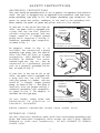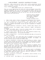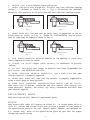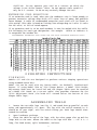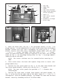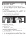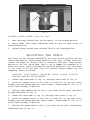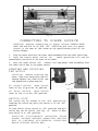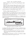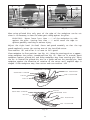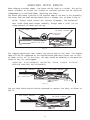
1
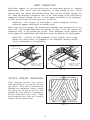
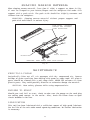
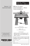
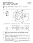
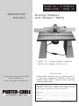
E S PA OL: P`GINA 19
FRAN˙AISE : PAGE 37
Instruction
manual
Router/Shaper
and Shaper Table
MODEL 697 Router/Shaper Complete
MODEL 698 Shaper Table Only
To learn more about Porter-Cable
visit our website at:
http://www.porter-cable.com
IMPORTANT
Please make certain that the person who is
to use this equipment carefully reads and
understands these instructions before
starting operations.
The Model and Serial No. plate is located on the main
housing of the tool. Record these numbers in the
spaces below and retain for future reference.
Model No. __________________________________
Type_______________________________________
Serial No. ___________________________________
Part No. 884901-991
SAFETY INSTRUCTIONS
GROUNDING INSTRUCTIONS
This tool should be grounded while in use to protect the operator from electric
shock. The tool is equipped with an approved three-conductor cord and threeprong grounding type plug to fit the proper grounding type receptacle. The
green (or green and yellow) conductor in the cord is the grounding wire.
Never connect the green (or green and yellow) wire to a live terminal.
If your unit is for use on less than 150
Volts, the power cord is equipped with
a plug that has two flat, parallel
current-carrying prongs and one
longer, round or U -shaped, ground
prong which requires a mating 3conductor grounded type receptacle,
as shown in Fig. 1.
An adapter, shown in Fig. 2, is
available for connecting 3-prong
grounding type plugs that are used on
units less than 150 Volts to 2-prong
receptacles. THIS ADAPTER IS NOT
ALLOWED IN CANADA. The green
colored rigid ear, lug, etc., must be
connected to a permanent ground
such as a properly grounded outlet
box, as shown in Fig. 2.
If your unit is for use on 150 to 250
Volts, the power cord is equipped with
a plug that has two flat current
carrying prongs in tandem, and one
round or U -shaped, longer ground
prong, as shown in Fig. 3. This plug is
used only with the proper mating 3conductor grounding type receptacle,
as shown in Fig. 3. No adapter is
available for this type plug.
IN ALL CASES, MAKE SURE THE
RECEPTACLE IN QUESTION IS
PROPERLY GROUNDED.
GROUNDED OUTLET BOX
CURRENT
CARRYING
PRONGS
GROUNDING PRONG
IS LONGEST OF THE 3 PRONGS
Fig. 1
GROUNDED OUTLET BOX
GROUNDING MEANS
ADAPTER
Fig. 2
GROUNDED OUTLET BOX
CURRENT
CARRYING
PRONGS
GROUNDING PRONG
IS LONGEST OF THE 3 PRONGS
Fig. 3
NEVER REMOVE GROUNDING PRONG FROM POWER PLUG.
EXTENSION CORDS
Use only three-wire extension cords which have three-prong grounding-type
plugs and three-pole receptacle which accept the tool s plug. Replace
damaged or worn cord immediately. DO NOT ATTEMPT TO REPAIR
POWER CORD.
2
IMPORTANT SAFETY INSTRUCTIONS
WARNING: When using electric tools, basic safety precautions should
always be followed to reduce the risk of fire, electric shock and personal
injury, including the following:
READ AND FOLLOW ALL INSTRUCTIONS.
There are certain applications for which this tool was designed. Porter-Cable
strongly recommends that this tool NOT be modified and/or used for any
application other than for which it was designed. If you have any questions
relative to its application DO NOT use the tool until you have written PorterCable and we have advised you.
Technical Service Manager
Porter-Cable Corporation
4825 Highway 45 North
P. O. Box 2468
Jackson, TN 38302-2468
1.
KEEP WORK AREA CLEAN. Cluttered areas and benches invite injuries.
2. AVOID DANGEROUS ENVIRONMENT. Don t expose power tools to
rain. Don t use power tools in damp or wet locations. Keep area well lit. Avoid
chemical or corrosive environment. Do not use tool in presence of flammable
liquids or gases.
3. GUARD AGAINST ELECTRIC SHOCK. Prevent body contact with
grounded surfaces. For example: pipes, radiators, ranges, refrigerator
enclosures.
4. KEEP CHILDREN AWAY. Do not let visitors contact tool or extension
cord. All visitors should be kept away from work area.
5. STORE IDLE TOOLS. When not in use, tools should be stored in dry,
and high or locked-up place out of reach of children.
6. DON T FORCE TOOL. It will do the job better and safer at the rate for
which it was intended.
7. USE RIGHT TOOL. Don t force small tool or attachment to do the job of
a heavy duty tool. Don t use tool for purpose not intended for example do
not use a circular saw for cutting tree limbs or logs.
8. DRESS PROPERLY. Do not wear loose clothing or jewelry. Loose
clothing, draw strings and jewelry can be caught in moving parts. Rubber
gloves and non-skid footwear are recommended when working outdoors.
Wear protective hair covering to contain long hair.
9. USE SAFETY GLASSES. Wear safety glasses or goggles while
operating power tools. Also face or dust mask if operation creates dust. All
persons in the area where power tools are being operated should also wear
safety glasses and face or dust mask.
10. DON T ABUSE CORD. Never carry tool by cord or yank it to disconnect
from receptacle. Keep cord from heat, oil, and sharp edges. Have damaged
or worn power cord and strain reliever replaced immediately. DO NOT
ATTEMPT TO REPAIR POWER CORD.
11. MAKE WORKSHOP KIDPROOF. Use padlocks, master switches, or by
removing starter keys.
12. SECURE WORK. Use clamps or a vise to hold work when practical.
3
13. DON T OVERREACH. Keep proper footing and balance at all times.
14. MAINTAIN TOOLS WITH CARE. Keep tools sharp and clean for better
and safer performance. Follow instructions for lubricating and changing
accessories. Inspect tool cords periodically and if damaged, have repaired by
authorized service facility. Inspect extension cords periodically and replace if
damaged. Have all worn, broken or lost parts replaced immediately. Keep
handles dry, clean and free from oil and grease.
15. DISCONNECT TOOLS when not in use, before servicing, and when
changing accessories such as blades, bits, cutters, etc.
16. REMOVE ADJUSTING KEYS AND WRENCHES. Form habit of checking
to see that keys and adjusting wrenches are removed from the tool before
turning it on.
17. AVOID UNINTENTIONAL STARTING. Do not carry a plugged-in tool
with finger on switch. Be sure switch is off when plugging in. Keep hands,
body and clothing clear of blades, bits, cutters, etc. when plugging in the tool.
18. OUTDOOR USE EXTENSION CORDS. When tool is used outdoors, use
only extension cords marked Suitable for use with outdoor appliances store
indoors when not in use.
19. STAY ALERT. Watch what you are doing. Use common sense. Do not
operate tool when you are tired or while under the influence of medication,
alcohol or drugs.
20. USE RECOMMENDED ACCESSORIES. Consult the owner s manual for
recommended accessories. The use of improper accessories may cause risk
of injury to persons.
21. NEVER STAND ON TOOL. Serious injury could occur if the tool is tipped
or if the cutting tool is unintentionally contacted.
22. CHECK DAMAGED PARTS. Before further use of the tool, a guard or
other part that is damaged should be carefully checked to determine that it will
operate properly and perform its intended function. Check for alignment of
moving parts, binding of moving parts, breakage of parts, mounting, and any
other conditions that may affect its operation. A guard or other part that is
damaged should be properly repaired or replaced.
23. DIRECTION OF FEED. Feed work into a blade or cutter against the
direction of rotation of the blade or cutter only.
24. NEVER LEAVE TOOL RUNNING UNATTENDED. TURN POWER OFF.
Don t leave tool until it comes to a complete stop.
25. WEAR EAR PROTECTION to safeguard against possible hearing loss.
SAVE THESE INSTRUCTIONS
ADDITIONAL SAFETY RULES FOR ROUTER/SHAPER
1.
DO NOT USE awkward hand positions.
2. KEEP FINGERS AWAY from revolving cutter
necessary.
use fixtures when
3.
USE CUTTER GUARDS for all applications.
4.
KEEP CUTTER GUARDS IN PLACE and in working order.
5.
KEEP CUTTERS SHARP.
4
6.
NEVER RUN STOCK between fence and cutter.
7. WHEN SHAPING with piloted bit, the pilot must have sufficient bearing
surface (1… 8" minimum) as shown in Fig. 1. Fig. 2 illustrates the INCORRECT
method for this operation as the pilot DOES NOT have sufficient bearing surface.
CORRECT
INCORRECT
Fig. 1
Fig. 2
8. WHEN SHAPING, the work must be fairly heavy in proportion to the cut
being made as shown in Fig. 3. UNDER NO CIRCUMSTANCE should short
work of light body be shaped as shown in Fig. 4.
CORRECT
INCORRECT
Fig. 3
Fig. 4
9. THE FENCE should be adjusted endwise so the opening is never more
than is required to clear the cutter.
10. CLAMP OR BOLT shaper table securely to workbench to prevent
walking .
11. DO NOT USE router bits larger in diameter than those recommended for
your router (see SELECTING THE BIT).
12. WHEN SHAPING NARROW MATERIAL, use a push stick and make
sure the material is properly supported.
13. WHEN END SHAPING, make sure the material is properly supported by
using a miter gauge or back-up block.
14. SOME WOOD CONTAINS PRESERVATIVES WHICH CAN BE TOXIC.
Take extra care to prevent inhalation and skin contact when working with
these materials. Request, and follow, any safety information available from
your material supplier.
REPLACEMENT PARTS
When servicing use only identical replacement parts.
M O TOR
Many Porter-Cable tools will operate on either D.C., or single phase 25 to 60
cycle A.C. current and voltage within plus or minus 5 percent of that shown on
the specification plate on the tool. Several models, however, are designed for
A.C. current only. Refer to the specification plate on your tool for proper
voltage and current rating.
5
CAUTION: Do not operate your tool on a current on which the
voltage is not within correct limits. Do not operate tools rated A.C.
only on D.C. current. To do so may seriously damage the tool.
EXTENSION CORD SELECTION
If an extension cord is used, make sure the conductor size is large enough to
prevent excessive voltage drop which will cause loss of power and possible
motor damage. A table of recommended extension cord sizes will be found in
this section. This table is based on limiting line voltage drop to 5 volts (10 volts
for 230 volts) at 150% of rated amperes.
If an extension cord is to be used outdoors it must be marked with the suffix
W-A following the cord type designation. For example SJTW-A to indicate it
is acceptable for outdoor use.
RECOMMENDED EXTENSION CORD SIZES FOR USE WITH PORTABLE ELECTRIC TOOLS
O P E R ATING INSTRUCTIONS
FOREWORD
Models 697 and 698 are designed to perform various shaping operations
using standard router bits.
Model 698 can be used with any Porter-Cable (or Rockwell) Professional
Router. If using Model 7538 or 7539 Plunge Router: a Model 75300 Height
Adjustment Knob must be installed and the Shaper Table must be mounted
on a Model 6961 Stand (or a cut-out table) that provides clearance for the
75300 Adjustment Knob (the knob will extend below the bottom of the
Shaper Table legs).
ASSEMBLING TA B L E
1. Locate the two table legs (see Fig. 5) and stand them up parallel to each
other and approximately 12" apart. The leg with the switch mounted in it
should be to your right, with the switch facing you. Both legs should slant
toward the outside.
2. Open hardware package.
3. Place the table on top of the legs, with the miter gauge slot up and the
large hole to the rear. Secure the table to the legs with four 1… 4-20 ¥ 13… 8"
long, flat head screws, split lockwashers, and nuts.
6
G
H
A
B
C
D
E
J
D
F
E
B
A
F
G
H
J
C
Left Leg
Right Leg
Table
Left Fence Bracket
Right Fence Bracket/
Guard Assembly
Fence (2)
Rear Cutter Guard/
Dust Port
Hardware Package
Miter Gage
Fig. 5
A
A
Fig. 6
Fig. 7
4. Mount the router base (see Fig. 6 for non-plunge routers, or Fig. 7 for
plunge routers), to the underside of the table using screws from the hardware
package (routers with less than 2 horsepower use three #10-24 x 3… 4" long
screws, routers with more than 2 horsepower except Model 7529 use four
5
… 16"-18 x 11… 4" screws, and Model 7529 uses three 10-24 x 11… 16" screws).
Orient the router base directly below the large hole in the table, with the clamp
screw (A) Fig. 6, (or the plunge locking lever (A) Fig. 7, on plunge models),
toward the rear of the table.
NOTE: The router sub-base must be removed before mounting to
table.
5. Place router motor into base and tighten clamp screw to secure (nonplunge models only).
6. Position the rear cutter guard (A) Fig. 8, to the right fence bracket and
top cutter guard assembly. Secure with two #10-32 x 3… 8" screws.
NOTE: The rear cutter guard also provides a 21… 2" diameter dust
collection port.
7. Position the right hand (in-feed) fence bracket and guard assembly (A)
Fig. 9, to the slot on the right side of the table. Insert a 5… 16"-18 x 11… 4"
carriage bolt (from the hardware package), up through the table and the fence
bracket. Secure by threading on one of the black knobs.
7
A
B
A
Fig. 9
Fig. 8
8. Assemble the left hand (out-feed) fence bracket (B) Fig. 9, to the table in
a similiar fashion.
9. Position the wooden fences to the fence brackets (see Fig. 10), and
secure using one, 3… 8"-16 x 11… 5" bolt and matching nut, through each fence
and fence bracket.
Fig. 10
FASTENING ROUTER/SHAPER TO WORK BENCH
The Router/Shaper should be securely attached to a firm supporting structure
(such as a work bench) to prevent movement of the machine during use. Two
holes are provided in the bottom flange of each leg for mounting bolts, or the
bottom leg flanges may be clamped to the support with C-clamps.
SELECTING THE BIT
The Router/Shaper will accommodate bits with shanks that are installed
directly into the power unit collet. A table insert with the smallest diameter
hole that will clear the selected bit should always be used.
CAUTION: Do not use router bits larger in diameter than those
recommended for your router (see following chart):
8
PORTER-CABLE / ROCKWELL PROFESSIONAL ROUTERS
Router Model
Max. Bit Diameter
All Models rated less than 2 Horsepower
21… 8"
All Models rated over 2 Horsepower
31… 2"
INSTALLING AND REMOVING BIT
1. CAUTION: DISCONNECT MACHINE FROM POWER SOURCE.
2. Clean and insert shank of bit into collect until shank bottoms. Then back it
.
out approximately 1… 16"
3. Place chuck wrench (A) Fig. 11, through opening in rear of base and
engage flats of chuck.
4. Move chuck wrench (A) Fig. 11, to the left side of base opening: place
collet wrench (B) Fig. 11, through opening in router base, move collet wrench
to right side of base opening and engage flats of collet nut (or flats of collet
depending on the specific router motor being used).
5. Grasp both wrenches and squeeze together (see Fig. 12).
6. Repeat Steps 3 thru 5 until collet is tightened securely.
7. To remove the bit, reverse the foregoing procedure.
NOTE: Avoid possible damage to collet. Never tighten collet without bit.
A
B
Fig. 11
Fig. 12
ADJUSTING BIT EXPOSURE
CAUTION: DISCONNECT MACHINE FROM POWER SOURCE
BEFORE MAKING ADJUSTMENTS.
NON-PLUNGE ROUTER
1. Loosen clamp screw (A) Fig. 13.
2. Turn motor until desired bit exposure above table is reached: clockwise
rotation of motor (viewed from chuck end of motor) reduces bit exposure,
counterclockwise rotation increases bit exposure.
3. Firmly tighten clamp screw (A) Fig. 13, to secure motor in base.
PLUNGE ROUTER MODEL 693
1. Grasp motor unit firmly and hold while moving the plunge locking lever
(on the router), to the released position.
2. While holding the plunge release lever in the released position: lift motor
unit until desired bit exposure is reached.
3. Release the plunge locking lever and push lever to the locked position.
9
A
Fig. 13
PLUNGE ROUTER MODEL 7538 OR 7539
1.
Move the plunge locking lever (on the router), to the released position.
2. Rotate Model 75300 Height Adjustment Knob to raise or lower cutter to
the desired position.
3.
Release plunge locking lever and push lever to the locked position.
ADJUSTING THE FENCE
Each fence may be adjusted individually for front-to-back position and for
side-to-side position. Front-to-back position of the right (in-feed) fence will
control the amount of material that is removed in each pass. Front-to-back
position of the left (out-of-feed) fence is set to support the workpiece as it
leaves the cutter. Side-to-side position should be adjusted so that each fence
is just clear of the bit path (this will provide maximum support for the
workpiece). Adjust as follows:
CAUTION: DISCONNECT MACHINE FROM POWER SOURCE
BEFORE MAKING ADJUSTMENTS.
1.
Loosen right fence knob (A) Fig. 14, and right fence screw (B) Fig. 14.
2. Slide the wooden fence to the right to clear bit as you move fence
assembly into the desired position front-to-back . Tighten knob (A) Fig. 14, to
secure fence assembly in position.
3. Position right wooden fence so that it just clears the bit path, and secure
by tightening screw (B) Fig. 14.
4.
Loosen left fence knob (C) Fig. 14, and right fence screw (D) Fig. 14.
5. Slide the wooden fence to the left to clear bit as you move fence
assembly into the desired position front-to-back . Tighten knob (C) Fig. 14, to
secure fence assembly in position.
6. Position left wooden fence so that it just clears the bit path, and secure by
tightening screw (D) Fig. 14.
10
C
A
B
D
Fig. 14
CONNECTING TO POWER SOURCE
CAUTION: Before connecting to power source ALWAYS MAKE
SURE THE SWITCH IS IN THE OFF POSITION and that the power
circuit is the same as that shown on the specification plate of the
Router/Shaper.
1. Plug the motor cord into the short cord extending from the table switch box.
2. Turn the router motor switch ON
motor operation will now be
controlled by the switch in the front of the table.
3. With the table switch OFF , connect the long power cord extending from
the table switch box to the power source.
STARTING AND STOPPING
THE MOTO R
CAUTION: Before starting the
motor, make sure work piece and all
foreign objects are clear of bit and
that guards are in place over bit.
TO START MOTOR
Move switch
lever (A) Fig. 15 up to the ON position.
A
Fig. 15
TO STOP MOTOR
Move switch
lever (A) Fig. 15 to the OFF position.
SWITCH LOCK
The switch may be locked in the OFF position by
removing the switch key while the switch is in the OFF
position.
To lock switch, place switch in OFF position and pull
switch key out of switch (see Fig. 16). Check to make
sure switch is in OFF position.
CAUTION: D I S C O N N E C T M A C H I N E F R O M
POWER SOURCE BEFORE REMOVING SWITCH
KEY TO PREVENT ACCIDENTAL STARTING
WHILE PULLING SWITCH KEY.
A
Fig. 16
11
USING THE ROUTER/SHAPER
WARNING: Figures 17 and 20 through 27 show machine with cutter
guards removed for clarity. NEVER O P E R A T E Router/Shaper without
guards in place.
IMPORTANT: Before using your machine, consider the kind and total
amount of rnaterial to be removed. Depending on the material, it may be
necessary to make more than one cut to avoid overloading the motor.
Before beginning the cut on the actual workpiece, it is advisable to
make a sample cut on a piece of scrap lumber. This will show exactly
how the cut will look as well as enable you to check dimensions.
The cutter rotates in a counterclockwise direction (viewing from above).
Always feed work against the cutter rotation as shown in Fig. 17.
WARNING: Serious injury could result if workpiece is not always fed
into the cutter against the direction of rotation.
The speed and depth of cut will depend largely on the type of material being
worked upon. Keep the cutting pressure constant but do not crowd the
machine so the motor speed slows excessively. It may be necessary on
exceptionally hard woods or problem materials to make more than one pass
at various settings to get the desired depth of cut.
When making cuts on all four edges of the workpiece, it is advisable to have
the first cut on the end of the piece across the grain. Thus, if chipping of wood
occurs at the end of a cut, it will be removed when making the next cut
parallel with the grain.
OUT-FEED FENCE
IN-FEED FENCE
CUTTING
CIRCLE
DEPTH OF CUT
FEED
Fig. 17
SHAPING WITH PILOTED BITS
For shaping irregular edges a starting pin (A) Fig. 19, is furnished with your
Router/Shaper for use with piloted router bits. Before installing the starting
pin, remove: the retaining clips (A) Fig. 18, the front guard (B) Fig. 18, and the
left hand (out-feed) fence assembly.
WARNING: Do not remove the right hand (in-feed) fence, top cutter
guard, and rear cutter guard assembly. This assembly must remain
in place and be adjusted so that the top guard completely covers the
installed cutter.
Insert starting pin into either hole (C) or (D) Fig. 19. For majority of shaping
operations the starting pin should be installed in hole (C) Fig. 19, as work
must be fed against the direction of rotation of the cutter.
12
B
A
A
A
D
C
Fig. 19
Fig. 18
When using piloted bits only part of the edge of the workpiece can be cut
since it is necessary to have the other part riding against the pilot.
WARNING: Never leave less than 1… 8" of the workpiece to ride
against the pilot. Leaving less than 1… 8" could cause the edge to
splinter possibly resulting in serious injury.
Adjust the right hand (in-feed) fence and guard assembly so that the top
guard completely covers the cutting area of the installed cutter.
Turn machine ON and allow it to come to full speed.
Place workpiece in first position (see Fig. 20). Using the starting pin as a support,
swing workpiece into cutter (second position Fig. 20). When cut is started, press
workpiece against piloted bit and swing workpiece away from starting pin. After
the cut is started the piloted bit acts as a guide and not the starting pin. Feed
workpiece against the direction of rotation of the cutter until complete edge is
shaped. Slide workpiece away from cutter and turn machine OFF .
STARTING PIN
1ST POSITION
CUTTING CIRCLE
2ND POSITION
PILOT
WORK
PILOT
STARTING PIN
CUTTING CIRCLE
WORK
2ND POSITION
3RD POSITION
Fig. 20
13
SHAPING WITH FENCE
When shaping straight edges, the fence can be used as a guide. The entire
fence assembly or either the infeed or outfeed section can be adjusted
independently as outlined under Adjusting the Fence .
For normal work where a portion of the original edge of the work is not altered by
the cutter, both the front and rear fences are in a straight line, as shown in Fig. 21.
NOTE: Always check fences for correct alignment. The workpiece
must slide along both fences smoothly. Always make a trial cut on
scrap material to check your set-up.
OUT-FEED FENCE
IN-FEED FENCE
CUTTING
CIRCLE
DEPTH OF CUT
FEED
Fig. 21
For shaping operations that remove the entire end of the work, the shaped
edge will not be supported by the outfeed fence when both fences are in-line,
as shown in Fig. 22. In this case, the work should be advanced to the position
shown in Fig. 22, and stopped.
CAUTION: DISCONNECT MACHINE FROM POWER SOURCE
BEFORE MAKING ADJUSTMENTS.
OUT-FEED FENCE
IN-FEED FENCE
NO SUPPORT
FEED
WORK
Fig. 22
The out-feed fence should then be advanced to contact the work, as shown in
Fig. 23.
OUT-FEED FENCE
IN-FEED FENCE
FEED
Fig. 23
14
END SHAPING
Sufficient support of the work piece must be maintained during all shaping
operations. This exists when the workpiece is long enough to rest firmly
against both the infeed and outfeed fences when you are halfway through the
cut. When end shaping a workpiece that is not long enough to be sufficiently
supported halfway through the cut, a miter gauge (available as an accessory)
or back-up block must be used (see Fig. 24 and 25).
WARNING: Any attempt to end shape a narrow workpiece without
sufficient support could result in serious injury.
When using the miter gauge, the infeed fence assembly must be parallel to the
miter slot. The outfeed fence must be adjusted so that it will not contact the
workpiece after it has passed the cutter. Place workpiece firmly against the
miter gauge and infeed fence and feed into cutter by pushing the miter gauge.
WARNING: Failure to hold workpiece firmly against miter gauge
during cut could result in slippage of the workpiece causing serious
injury and damage to the workpiece.
MITER GAUGE
BACK-UP
BLOCK
WARNING: KEEP
HANDS AWAY
FROM CUTTER
WARNING: KEEP
HANDS AWAY
FROM CUTTER
Fig. 24
Fig. 25
CROSS-GRAIN SHAPING
When shaping across the grain,
some splitting at the end of the cut
may result. This can be minimized by
feeding the workpiece slowly across
the cutter at the end of the cut. When
shaping all four sides of a workpiece,
do the cross-grain cuts first. Doing
with-the-grain cuts last will usually
remove the splintered end.
Fig. 26
15
SHAPING NARROW MATERIAL
When shaping narrow material (less than 3" wide) a support as shown in Fig.
27 must be clamped to your Router/Shaper and the workpiece fed under this
support with a push stick. The push stick should be slightly narrower and
thinner than the workpiece.
WARNING: Shaping narrow material without proper support and
push stick could result in serious injury.
18
"
PUSH STICK
SLIGHTLY
NARROW AND THINNER
THAN WORKPIECE
WORK SUPPORT
WORKPIECE
WARNING: KEEP HANDS AWAY FROM CUTTER
Fig. 27
MAINTENANCE
K E E P TO O L C L E A N
Periodically blow out all air passages with dry compressed air. Remove
buildup of grime resulting from working with green or sappy wood. All plastic
parts should be cleaned with a soft damp cloth. NEVER use solvents to clean
plastic parts. They could possibly dissolve or otherwise damage the material.
CAUTION: Wear safety glasses while using compressed air.
FAILURE TO STA R T
Should your tool fail to start, check to make sure the prongs on the cord plug
are making good contact in the outlet. Also, check for blown fuses or open
circuit breakers in the line.
LUBRICATION
This tool has been lubricated with a sufficient amount of high grade lubricant
for the life of the unit under normal operating conditions. No further lubrication
is necessary.
16
BRUSH INSPECTION
At approximately 100 hours of use, take or send your tool to your nearest
Authorized Porter-Cable Service Station to be thoroughly cleaned and
inspected; worn parts replaced, when necessary; relubricated with fresh
lubricant, if required; reassembled with new brushes; and performance tested.
Any loss of power before the above maintenance check may indicate the
need for immediate servicing of your tool. DO NOT CONTINUE TO
OPERATE TOOL UNDER THIS CONDITION. If proper operating voltage is
present, return your tool to the Service Station for immediate service.
S E RVICE AND REPAIRS
All quality tools will eventually require servicing or replacement of parts due to
wear from normal use. These operations, including brush inspection and
replacement, should ONLY be performed by either an AUTHORIZED
PORTER-CABLE SERVICE STATION or a PORTER-CABLE SERVICE
CENTER. All repairs made by these agencies are fully guaranteed against
defective material and workmanship. We cannot guarantee repairs made or
attempted by anyone other than these agencies.
Should you have any questions about your tool, feel free to write us at any
time. In any communications, please give all information shown on the
nameplate of your tool (model number, type, serial number, etc.).
ACCESSORIES
The testing of this tool has been accomplished with the following accessories.
For safest operation, it is recommended that only these accessories be used
with this product.
WARNING: Since accessories other than those listed have not been
tested with this product, use of such accessories could be hazardous.
6970
75300
6961
42596
Miter Gage
Plunge Router Height Adjustment Knob
(use with Models 7538 and 7539)
Shaper Table Stand
Collet Wrench
17
PORTER-CABLE LIMITED
ONE YEAR WA R R A N T Y
Porter-Cable warrants its Professional Power Tools for a period of one year from the date of original
purchase. We will repair or replace, at our option, any part or parts of the product and accessories
covered under this warranty which, after examination, proves to be defective in workmanship or
material during the warranty period. For repair or replacement, return the complete tool or accessory,
transportation prepaid, to your nearest Porter-Cable Service Center or Authorized Service Station.
Proof of purchase may be required. This warranty does not apply to repair or replacement required
due to misuse, abuse, normal wear and tear or repairs attempted or made by other than our Service
Centers or Authorized Service Stations.
ANY IMPLIED WARRANTY, INCLUDING THE IMPLIED WARRANTIES OF MERCHANTABILITY
AND FITNESS FOR A PARTICULAR PURPOSE, WILL LAST ONLY FOR ONE (1) YEAR FROM
THE DATE OF PURCHASE.
To obtain information on warranty performance please write to: PORTER-CABLE CORPORATION,
4825 Highway 45 North, P.O. Box 2468, Jackson, Tennessee 38302-2468; Attention: Product
Service. THE FOREGOING OBLIGATION IS PORTER-CABLE S SOLE LIABILITY UNDER THIS
OR ANY IMPLIED WARRANTY AND UNDER NO CIRCUMSTANCES SHALL PORTER-CABLE BE
LIABLE FOR ANY INCIDENTAL OR CONSEQUENTIAL DAMAGES. Some states do not allow
limitations on how long an implied warranty lasts or the exclusion or limitation of incidental or
consequential damages, so the above limitation or exclusion may not apply to you.
This warranty gives you specific legal rights and you may also have other legal rights which vary from
state to state.
18
PORTER-CABLE SERVICE CENTERS
(CENTROS DE SERVICIO DE PORTER-CABLE)
(CENTRE DE SERVICE PORTER-CABLE)
Parts and Repair Service for Porter-Cable Power Tools are Available at These Locations
(Obtenga Refaccion de Partes o Servicio para su Herramienta en los Siguientes Centros de Porter-Cable)
(Locations oø vous trouverez les piŁces de rechange nØcessaires ainsi qu un service d entretien)
ARIZONA
Tempe 85282 (Phoenix)
2400 West Southern Avenue
Suite 105
Phone: (602) 437-1200
Fax: (602) 437-2200
GEORGIA
Forest Park 30297 (Atlanta)
5442 Frontage Road, Suite 112
Phone: (404) 608-0006
Fax: (404) 608-1123
MINNESOTA
Minneapolis 55429
4315 68th Avenue North
Phone: (612) 561-9080
Fax: (612) 561-0653
Cleveland 44125
8001 Sweet Valley Dr.
Unit #19
Phone: (216) 447-9030
Fax: (216) 447-3097
CALIFORNIA
Ontario 91761 (Los Angeles)
3949A East Guasti Road
Phone: (909) 390-5555
Fax: (909) 390-5554
ILLINOIS
Addison 60101 (Chicago)
311 Laura Drive
Phone: (630) 628-6100
Fax: (630) 628-0023
MISSOURI
North Kansas City 64116
1141 Swift Avenue
P.O. Box 12393
Phone: (816) 221-2070
Fax: (816) 221-2897
PENNSYLVANIA
Willow Grove 19090
520 North York Road
Phone: (215) 658-1430
Fax: (215) 658-1433
San Leandro 94577 (Oakland)
3039 Teagarden Street
Phone: (510) 357-9762
Fax: (510) 357-7939
COLORADO
Denver 80216
5855 Stapleton Drive North
Suite A-140
Phone: (303) 370-6909
Fax: (303) 370-6969
FLORIDA
Hialeah 33014 (Miami)
16373-75 NW 57th Ave.
Phone: (305) 624-2523
Fax: (305) 628-2654
Tampa 33609
4538 W. Kennedy Boulevard
Phone: (813) 877-9585
Fax: (813) 289-7948
MARYLAND
Elkridge 21075 (Baltimore)
7397-102 Washington Blvd.
Phone: (410) 799-9394
Fax: (410) 799-9398
MASSACHUSETTS
Franklin 02038 (Boston)
Franklin Industrial Park
101E Constitution Blvd.
Phone: (508) 520-8802
Fax: (508) 528-8089
MICHIGAN
Troy 48083 (Detroit)
1355 Combermere
Phone: (248) 597-5000
Fax: (248) 597-5004
St. Louis 63119
7574 Watson Road
Phone: (314) 968-8950
Fax: (314) 968-2790
TENNESSEE
Nashville 37214
2262 Lebanon Pike
Phone: (615) 882-0320
Fax: (615) 882-0051
NEW YORK
Flushing 11365-1595 (N.Y.C.)
175-25 Horace Harding Expwy.
Phone: (718) 225-2040
Fax: (718) 423-9619
TEXAS
Dallas 75220
10720 N. Stemmons Freeway
Phone: (214) 353-2996
Fax: (214) 350-3943
NORTH CAROLINA
Charlotte 28209
4303-B South Boulevard
Phone: (704) 525-4410
Fax: (704) 525-0618
Houston 77055
West 10 Business Center
1008 Wirt Road, Suite 120
Phone: (713) 682-0334
Fax: (713) 682-4867
OHIO
Columbus 43214
4560 Indianola Avenue
Phone: (614) 263-0929
Fax: (614) 263-1238
WASHINGTON
Renton 98055 (Seattle)
268 Southwest 43rd Street
Phone: (425) 251-6680
Fax: (425) 251-9337
Authorized Service Stations are located in many large cities. Telephone 800-487-8665 or 901-541-6042 for assistance locating one. Parts
and accessories for Porter-Cable products should be obtained by contacting any Porter-Cable Distributor, Authorized Service Center, or
Porter-Cable Factory Service Center. If you do not have access to any of these, call 888-848-5175 and you will be directed to the nearest
Porter-Cable Factory Service Center. Las Estaciones de Servicio Autorizadas estÆn ubicadas en muchas grandes ciudades. Llame al
800-487-8665 al 901-541-6042 para obtener asistencia a fin de localizar una. Las piezas y los accesorios para los productos PorterCable deben obtenerse poniØndose en contacto con cualquier distribuidor Porter-Cable, Centro de Servicio Autorizado o Centro de
Servicio de FÆbrica Porter-Cable. Si no tiene acceso a ninguna de estas opciones, llame al 888-848-5175 y le dirigirÆn al Centro de
Servicio de FÆbrica Porter-Cable mÆs cercano. Des centres de service agrØØs sont situØs dans beaucoup de grandes villes. Appelez au
800-487-8665 ou au 901-541-6042 pour obtenir de l aide pour en repØrer un. Pour obtenir des piŁces et accessoires pour les produits
Porter-Cable, s adresser tout distributeur Porter-Cable, centre de service agrØØ ou centre de service d usine Porter-Cable. Si vous n avez
accŁs aucun de ces centres, appeler le 888-848-5175 et on vous dirigera vers le centre de service d usine Porter-Cable le plus proche.
D E LTA S E RVICE CENTERS
ALBERTA
Bay 6, 2520-23rd St. N.E.
Calgary, Alberta
T2E 8L2
Phone: (403) 735-6166
Fax: (403) 735-6144
MANITOBA
1699 Dublin Avenue
Winnipeg, Manitoba
R3H 0H2
Phone: (204) 633-9259
Fax: (204) 632-1976
BRITISH COLUMBIA
8520 Baxter Place
Burnaby, B.C.
V5A 4T8
Phone: (604) 420-0102
Fax: (604) 420-3522
ONTARIO
644 Imperial Road
Guelph, Ontario
N1H 6M7
Phone: (519) 836-2840
Fax: (519) 767-4131
QU BEC
1515 ave.
St-Jean Baptiste,
QuØbec, QuØbec
G2E 5E2
Phone: (418) 877-7112
Fax: (418) 877-7123
1447, Begin
St-Laurent, (MontrØal), QuØbec
H4R 1V8
Phone: (514) 336-8772
Fax: (514) 336-3505
The following are trademarks of PORTER-CABLE Corporation (Las siguientes son marcas registradas de PORTER-CABLE S.A.) (Les marques
suivantes sont des marques de fabriquant de la PORTER-CABLE Corporation): PORTER-CABLEfi , OMNIJIGfi , POCKET CUTTERfi , PORTAB A N Dfi , PORTA-PLANEfi , QUICKSANDfi , VERSA-PLANEfi , SANDTRAPfi , SAW BOSSfi , SPEED-BLOCfi , SPEEDMATICfi , SPEEDTRONICfi ,
STAIR-EASE fi , THE PROFESSIONAL EDGE fi , TIGER CUB fi , TIGER SAW fi , TORQ-BUSTER fi , DURATRONIC , FRAME SAW ,
JETSTREAM , MICRO-SET , MORTEN , PROFESSIONAL SELECT , QUIK-CHANGE , TRU-MATCH , WOODWORKER S CHOICE .
Trademarks noted with fi are registered in the United States Patent and Trademark Office and may also be registered in other countries. Las
Marcas Registradas con el signo de fi son registradas por la Oficina de Registros y Patentes de los Estados Unidos y tambiØn pueden estar
registradas en otros pa ses. Marques dØposØes, indiquØes par la lettre fi, sont dØposØes au Bureau des brevets d invention et marques
dØposØes aux Etats-Unis et pourraient Œtre dØposØes aux autres pays.
Copyright ' 1998 PORTER-CABLE Corporation
Printed in U.S.A.