1
Installed Voice Business Group
RS-232 Command Set:
Vortex EF2211 Programming Guide
Copyright © 2003 Polycom, Inc.
Polycom and the Polycom logo are registered trademarks of Polycom, Inc.
ASPI, Vortex, VS4000, Viewstation, and iPower are
registered trademarks of Polycom, Inc.
All other brand names, product names, and trademarks are the
sole property of their respective owners
Vortex EF2211 Programming
Guide
Table of Contents
1. Introduction
2. RS-232 Hardware
3. Programming Tips
3.1. Initialization
3.2. Wildcard Characters
3.3. Using Acknowledgements
3.4. Macros and Presets
4. Command Structure
4.1. Device Type
4.2. Device ID
4.3. Command Name
4.4. Command Data
4.5. Command Terminator
4.6. Examples
5. Status Messages
6. Command Types
6.1. Boolean Commands
6.2. Integer Commands
6.3. Channel Commands
6.4. Matrix Commands
6.5. Miscellaneous Commands
7. Command List
8. Command Reference
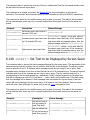
8.1. AA -- Enable or Disable Auto Answer Mode
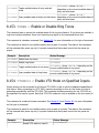
8.2. ACKMOD -- Enable or Disable Acknowledgment Mode
8.3. AEC -- Enable or Disable Acoustic Echo Cancellation
8.4. AECMODE -- Set Amount of Double Talk Suppression used in the AEC.
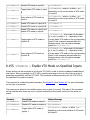
8.5. AGC -- Enable or Disable Mic/Line Input Automatic Gain Control
8.6. AGCMAX -- Set Maximum Allowed Mic/Line Input AGC Gain
8.7. AGCMIN -- Set Minimum Allowed Mic/Line Input AGC Gain
8.8. AGCRATE -- Set Ramp Rate of Mic/Line Input AGC
8.9. AHCP -- Enable or Disable Call Progress Based Auto Hangup
8.10. AHLD -- Enable or Disable Loop Drop Based Auto Hangup
8.11. AMASGN -- Assign Inputs to an Automixer
8.12. AMAUTO -- Select Automatic or Manual Gating for each Automixer Input
8.13. AMBUSID -- Set Automixer Groupings for EF Bus
8.14.
8.15.
8.16.
8.17.
8.18.
8.19.
8.20.
8.21.
8.22.
8.23.
8.24.
8.25.
8.26.
8.27.
8.28.
8.29.
8.30.
8.31.
8.32.
8.33.
8.34.
8.35.
8.36.
8.37.
8.38.
8.39.
8.40.
8.41.
8.42.
8.43.
8.44.
8.45.
8.46.
8.47.
8.48.
8.49.
8.50.
8.51.
8.52.
8.53.
8.54.
8.55.
8.56.
8.57.
8.58.
AMCHAIR -- Enable Chairman Mode for Specified Automixer
AMCHNUM -- Set Chairman Mic
AMDECAY -- Set Decay Time for Automixers
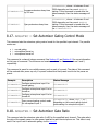
AMGATEC -- Set Automixer Gating Control Mode
AMGATER -- Set Automixer Gate Ratio
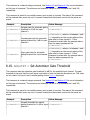
AMGATET -- Set Automixer Gate Threshold
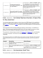
AMGNOM -- Set Global Maximum Number of Open Mics for Bus Automixer
AMHOLD -- Set Automixer Hold Time
AMLMM -- Set Last Mic On Mode for Specified Automixer
AMLMN -- Set Microphone That Will Remain On in Manual Last Mic On Mode
AMNOM -- Set Local Maximum Number of Open Mics for Automixer
AMNOMAT -- Select NOM Attenuation on Each Output
AMOFFAT -- Set Off Attenuation for the Specified Automixer
AMPRIOR -- Set Gating Priority for the Specified Mic
AMREFB -- Set Automixer Reference Bias for the Specified Automixer
AMREFE -- Enable Automixer Reference for Specified Automixer
BAUD -- Set Baud Rate for RS-232 Port
BLAUTO -- Enable Automatic BLDATA Messages
BLDATA -- Request Level Information
BLINFO -- Select Information to be Reported in BLDATA
BROAD2 -- Broadcast Arbitrary Command Strings to RS-232 Port
BROADA -- Broadcast Commands to Other Connected Devices
BUSREF -- Set Which AEC Reference is Placed on EF Bus
CGATE -- Query Camera Gating Status Information
CGATEEN -- Enable Automatic Camera Gating Messages
CGATET -- Set Camera Gating Hold Time
COUNTRY -- Specify Country Definitions for Phone Interface
DELAYO -- Set Output Delay
DELAYOE -- Enable Output Delay
DIAL -- Send DTMF Digits to Phone Interface
DSPAUTO -- Enable Automatic DSPLOAD Status Messages
DSPLOAD -- Query Percentage of Variable DSP Resources Used
ERROR -- Enable or Disable Error Messages
FADERGIL -- Set Fader Gain of Line Inputs as a Group
FADERI -- Set Input Gain Fader
FLASH -- Execute Hook Flash
FLOW -- Set Flow Control Mode for RS-232 Port
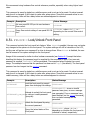
FPLOCK -- Lock/Unlock Front Panel
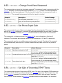
FPPSWD -- Change Front Panel Password
GAINA -- Set Phone Input Gain
GAIND -- Set Gain of Incoming DTMF Tones
GAINDIT -- Set Gain of Incoming DTMF Tones
GAINDT -- Set Dial Tone Gain
GAINGIL -- Set Gain of Line Inputs as a Group
GAINI -- Set Input Gain
8.59. GAINO -- Set Output Gain
8.60. GAINP -- Set Phone Output Gain
8.61. GAINSIT -- Set From Phone User Tone Gain
8.62. GAINSOT -- Set To Phone User Tone Gain
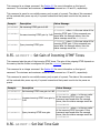
8.63. GATE -- Query Gating Status Information
8.64. GATEEN -- Enable Automatic Gating Messages
8.65. GMUTEO -- Mute All Outputs
8.66. ID -- Set Device ID
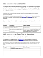
8.67. LABEL -- Set or Query one of the Device Labels
8.68. LAGC -- Enable or Disable Line Input Automatic Gain Control
8.69. LAGCLINKAB -- Enable or Disable Stereo AGC Linking on Inputs A and B
8.70. LAGCMAX -- Set Maximum Allowed Line Input AGC Gain
8.71. LAGCMIN -- Set Minimum Allowed Line Input AGC Gain
8.72. LAGCRATE -- Set Ramp Rate of Line Input AGC
8.73. LEC -- Enable or Disable LEC
8.74. LECMODE -- Set Amount of Double Talk Suppression used in the LEC.
8.75. LI -- Query State of Logic Inputs
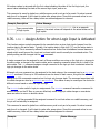
8.76. LIA -- Assign Action for when Logic Input is Activated
8.77. LID -- Assign Action for when Logic Input is Deactivated
8.78. LIH -- Assign Action for when Logic Input is Held
8.79. LIEN -- Enable Automatic Logic Input Status Messages
8.80. LIG -- Configure Logic Input Pins Into a Group
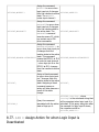
8.81. LIK -- Delete One or All Logic Input Pin Commands
8.82. LIM -- Mask Logic Input Pins
8.83. LIN -- Assign Command to Logic Input Group
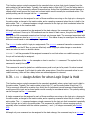
8.84. LIP -- Set Polarity for Logic Inputs
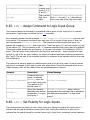
8.85. LO -- Query or Set Status of Logic Output Pins
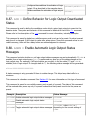
8.86. LOA -- Define Behavior for Logic Output Activated State
8.87. LOD -- Define Behavior for Logic Output Deactivated Status
8.88. LOEN -- Enable Automatic Logic Output Status Messages
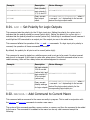
8.89. LOK -- Delete One or All Logic Output Pin Commands
8.90. LOM -- Mask Logic Output Pins
8.91. LOP -- Set Polarity for Logic Outputs
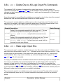
8.92. MACROA -- Add Command to Current Macro
8.93. MACROK -- Delete One or All Macros
8.94. MACROL -- List All Commmands in a Macro
8.95. MACROQ -- Execute Macro Quietly
8.96. MACROS -- Start a New Macro
8.97. MACROW -- Write Macro to Non-Volatile Memory
8.98. MACROX -- Execute Macro
8.99. METER -- Select which Signal is Displayed on the Front Panel LED Meter
8.100. MGAIN -- Set Crosspoint Gains in Main Matrix or Submatrix
8.101. MGATE -- Select Gated or Ungated Microphone Signal in Matrix
8.102. MIC -- Enable Microphone Gain Stage on Input 1
8.103. MINI -- Enable Modem Initialization String
8.104.
8.105.
8.106.
8.107.
8.108.
8.109.
8.110.
8.111.
8.112.
8.113.
8.114.
8.115.
8.116.
8.117.
8.118.
8.119.
8.120.
8.121.
8.122.
8.123.
8.124.
8.125.
8.126.
8.127.
8.128.
8.129.
8.130.
8.131.
8.132.
8.133.
8.134.
8.135.
8.136.
8.137.
8.138.
8.139.
8.140.
8.141.
8.142.
8.143.
8.144.
8.145.
8.146.
8.147.
8.148.
MINISTR -- Set Modem Initialization String
MMUTE -- Mute Crosspoint in Main Matrix or Submatrix
MUTEGIL -- Set Mute Status of Line Inputs as a Group
MUTEI -- Mute One or More Inputs
MUTEO -- Mute One or More Outputs
NC -- Enable Noise Cancellation
NCL -- Set Noise Cancellation Attenuation
NVINIT -- Reinitialize Non-Volatile Memory
NVLOCK -- Lock/Unlock Non-Volatile Memory
NVPSWD -- Change Non-Volatile Memory Password
PEQIA -- Set All Parameters for Specified Parametric EQ Input Stage
PEQIB -- Set Bandwidth Parameter for Specified Parametric EQ Input Stage
PEQIE -- Set Enabled Parameter for Specified Parametric EQ Input Stage
PEQIF -- Set Frequency Parameter for Specified Parametric EQ Input Stage
PEQIG -- Set Gain Parameter for Specified Parametric EQ Input Stage
PEQIS -- Set Slope Parameter for Specified Parametric EQ Input Stage
PEQIT -- Set Type Parameter for Specified Parametric EQ Input Stage
PEQOA -- Set All Parameters for Specified Parametric EQ Output Stage
PEQOB -- Set Bandwidth Parameter for Specified Parametric EQ Output Stage
PEQOE -- Set Enabled Parameter for Specified Parametric EQ Output Stage
PEQOF -- Set Frequency Parameter for Specified Parametric EQ Output Stage
PEQOG -- Set Gain Parameter for Specified Parametric EQ Output Stage
PEQOS -- Set Slope Parameter for Specified Parametric EQ Output Stage
PEQOT -- Set Type Parameter for Specified Parametric EQ Output Stage
PHANTOM -- Enable Phantom Power on Input 1
PHONE -- Take Phone On-Hook or Off-Hook
PING -- See Which Devices Are Present
PRESETK -- Delete One or All Presets
PRESETL -- List All Commmands in a Preset
PRESETP -- Set Which Preset Will Be Activated At Power-Up
PRESETQ -- Execute a Preset Quietly
PRESETW -- Save a Preset
PRESETX -- Execute a Preset
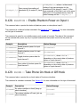
REDIAL -- Redial the Last Dialed Phone Number
REFASGN -- Assign AEC Reference to Input Channel
REFGAIN -- Set Reference Output Gain
RING -- Enable or Disable Ring Messages
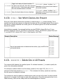
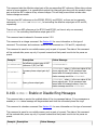
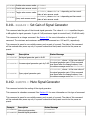
SGGAIN -- Set Gain of Signal Generator
SGMUTE -- Mute Signal Generator
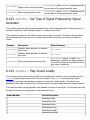
SGTYPE -- Set Type of Signal Produced by Signal Generator
SOUNDL -- Play Sound Locally
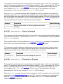
SOUNDP -- Play Sound to Phone
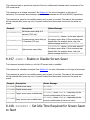
SSDELAY -- Set Delay Between Screen Saver Screens
SSEN -- Enable or Disable Screen Saver
SSSTART -- Set Idle Time Required for Screen Saver to Start
8.149.
8.150.
8.151.
8.152.
8.153.
8.154.
8.155.
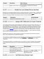
SSTEXT -- Set Text to be Displayed by Screen Saver
SWRESET -- Perform Soft Reset of System
SWVER -- Query Software Version
TONEE -- Enable or Disable Entry and Exit Tones
TONER -- Enable or Disable Ring Tones
VTXMODI -- Enable VTX Mode on Specified Inputs
VTXMODO -- Enable VTX Mode on Specified Inputs
1. Introduction
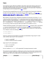
This document describes the command protocol that is used to communicate with the Vortex EF2211
via its RS-232 port.
2. RS-232 Hardware
The communication between the Vortex and a host controller is conducted via the RS-232 port on the
back panel of the Vortex. The Vortex's RS-232 port operates at the following settings:
●
●
●
Bit Rate (bps): 9600 (default), 19200, or 38400
Data Format: 8 data bits, no parity, 1 stop bit (8N1)
Flow Control: none (default) or hardware (RTS, CTS)
Note that although the flow control setting is user selectable to none or hardware, hardware flow
control must be used when updating the firmware of the Vortex. This means that while a 3-wire RS232 cable (RX, TX, GND) is acceptable for control of the Vortex, the minimum cable for updating
firmware should contain 5 wires (RX, TX, RTS, CTS, GND).
3. Programming Tips
3.1. Initialization
During power up of the Vortex device or initialization of the host program, electrical fluctuations on
the RS-232 lines may cause the Vortex to receive spurious data. After initialization, the host program
should send a few carriage return characters (^M, ASCII 13) to the connected Vortex to flush out any
spurious characters it may have received. Failure to do this could result in the Vortex ignoring the first
command received after initialization.
As part of the host program initialization, the host will want to synchronize the status of its controls
with the current status of the Vortex devices that are being controlled. The host could initialize its
controls to default values and then send commands to the Vortexes to set them to the same state.
This approach has significant disadvantages since initializing the host program could undo settings
made by other host programs or by the front panel controls of one of the linked Vortex devices. A
better approach is to query the linked Vortex devices for their status and set the host program
controls based on the return values.
3.2. Wildcard Characters
The use of the wildcard character, '*', can make programming the host controller much easier. Be
careful when using wildcards, however, since they can generate a lot of traffic on the digital bus.
3.3. Using Acknowledgements
It is a good idea for the host program or control system to make sure that all connected Vortex
devices have acknowledgment mode enabled (see the ACKMOD command). When acknowledgment
mode is on, a Vortex device will send an acknowledgment for each command it receives. Proper use
of acknowledgments makes the host program more robust and makes supporting multiple hosts
effortless. The rest of this section describes how to use acknowledgments to achieve these goals.
As a convenient example, let us imagine a host program with a graphical user interface (GUI). The
user presses buttons on the GUI to enable or disable features of various linked Vortex devices. The
buttons on the GUI reflect the current status of the corresponding feature.
When the user presses a button on the GUI to enable or disable a feature, the host program should
send the corresponding command to the selected Vortex device. It may be tempting to update the
status of the GUI button at this point, but this can cause problems if there are transmission errors or if
there are multiple host controllers. The proper way to handle this is to only update the GUI controls
based on acknowledgments received from the Vortex device.
To implement this, organize your code so that the functions that send commands are totally separate
from the functions that receive responses from the Vortex devices. This also enables your host
program to support the presence of multiple host controllers. For example, consider the following
sequence of events.
1. Another host sends a command to a Vortex device.
2. The Vortex device responds with an acknowledgment that is broadcast to all of the other hosts.
3. Your host program receives the acknowledgment and updates the status of the corresponding
control.
The result of this programming model is that all hosts and linked Vortex devices will always be
synchronized.
For simple on/off features, your host program can make use of the toggle arguments to some
commands (e.g., 'SSEN2'). By sending a toggle command when a button is pressed, and updating the
button based on acknowledgments, your host program will not have to keep track of the status of the
button.
In a similar fashion, many of the integer commands (such as gains) can be controlled by incrementing
or decrementing them by a specific amount. For example, the command 'GAINIA>1 ' increments the
input gain on channel A by 1 dB. The acknowledgment for this command will return the actual value
that the gain was incremented to. Thus, to implement a volume control, your control program can
send a command to increment the gain by 1 dB when the "up" button is pressed and decrement the
gain by 1 dB when the "down" button is pressed. The control can update its level indicator based on
the acknowledgment that is received.
3.4. Macros and Presets
Although macros and presets are similar, there are times when using one is better than the other.
Presets store the absolute values of all of the non-global settings of the device. This includes, but is
not limited to, input and output gain settings, matrix settings, algorithm settings, parametric EQ
settings, and automixer settings. See Section 7 for a list showing all the commands and which are
saved to presets.
Presets should be used when you really want to change all the settings in a device. One example
would be when you want to have one unit be able to control different rooms. In this case, having a
preset for each different room is the easiest solution.
Macros are like mini-presets. You can define them to change only the settings you are interested in.
One advantage of macros over presets is that macros can make relative changes in addition to
absolute changes. An absolute change is something like "set the input gain to -3 dB". A relative
change is something like "raise the input gain by 3 dB". One example of using macros for a relative
change is stereo volume ramping. If you have two outputs setup to have left and right program audio,
then you could build a macro that contains two commands: one to increment the left channel by 1 dB
and the other to increment the right channel by 1 dB. Then, by calling that macro, you can ramp the
stereo outputs. A similar thing can be done with decreasing the volume.
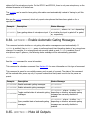
Another thing to consider when using macros and presets is to use the MACROQ and PRESETQ
commands instead of the MACROX and PRESETX commands. Both the Q and X versions execute the
macro or preset, but the X versions produce acknowledgements for the settings that change, while
the Q versions don't. If your control system updates its status by looking at the acknowledgements
that come back, then you'll probably want to use the X versions. Another option would be to use the Q
versions and then manually query the values you're interested in. If your control system does not
need use acknowledgements, or if you are manually querying the values you're interested in, using
the Q versions is better since it doesn't generate acknowledgements and thus reduces RS-232 traffic.
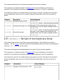
4. Command Structure
A Vortex command consists of a series of ASCII characters with the following structure.
Description
Number of Characters
Range of Values
Device Type
1
0-9, A-Z, *
Device ID
2
0-9, *
Command Name
1-7
0-9, A-Z
Command Data
0-64
ASCII characters
Command Terminator
1
^M (ASCII 13)
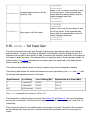
4.1. Device Type
A single alphanumeric character is used to indicate the device type. The devices in Polycom's
EchoFree family have the following device types.
Device
Device Type
EF200
A
EF1210
C
EF2280
F
EF2241
B
EF2211
S
EF2210
Q
EF2201
T
Device type '*' can be used to send a command to all device types simultaneously.
4.2. Device ID
Two numeric characters are used to indicate the device ID. The Vortex can be configured for device
IDs from '00' to '07'. Note that even though the device ID is less than 10, the leading '0' must be
included. Device ID '**' can be used to send a command to all device IDs simultaneously. Some
examples of using wildcard characters are given below.
●
●
●
'S**' broadcasts to all EF2211 devices that are linked together.
'*07' broadcasts to all devices with device ID 07 (this format is not commonly used).
'***' broadcasts to all devices that are linked together.
4.3. Command Name
The command name can be from 1 to 7 characters long. Command names will be specific to device
types. In other words, the EF2280 has its own command set, which is different from the EF2241's,
which is different from the EF1210's, etc. There are some commands, such as 'PING', that are
common among all the various command sets.
4.4. Command Data
The command data is a series of 0-64 characters containing payload data for the command.
Obviously, the command data will be specific to the command type. note that the maximum number
of payload characters for the EF200 and EF1210 is 32, but the Vortex devices support up to 64
characters in the payload. This increase was necessary to accommodate the matrix gain and
macro/preset commands.
4.5. Command Terminator
The command terminator is a single character indicating the end of a command. ASCII 13 (^M) was
chosen as the terminator to allow manually typing commands using a simple text terminal.
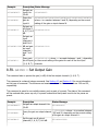
4.6. Examples
In the following examples, Vortex commands are enclosed in single quotes, 'like this'. Also, the
terminator character is not explicitly shown, but its presence is implied.
Consider the command '***PING'. The device type and ID for this command are wildcards, thus the
command will be sent to all devices. The command name in this case is 'PING', and there are no data
characters (payload). Note that the 'PING' command is supported by all of the Vortex devices, thus
broadcasting the command to all devices makes sense.
Consider the command 'S**GAINIA10'. The device type for this command is 'S' and the device ID is
a wildcard, thus the command will be broadcast to all EF2211 devices linked together. The command
name in this case is 'GAINIA' and the command data (payload) is '10'. This command sets the gain
on input A of all connected EF2211's to 10 dB.
Command
Effects
***PING
Requests PONG response from all linked Vortex devices.
S**GAINIA10
Sets the gain on input A of all connected EF2211 devices to 10 dB.
5. Status Messages
The Vortex sends status messages via RS-232 and EF Bus any time one of its internal parameters
changes. This means that the host program does not need to continually poll the Vortex in order to
detect status changes. Status messages are in the same format as the commands used to set the
corresponding parameter.
For example, suppose you send the command 'S**GAINIA10' and there are two EF2211's linked
together with device IDs 3 and 7. The EF2211's will respond with 'S03GAINIA10' and
'S07GAINIA10', respectively. Now, someone uses the front panel of the EF2211 set to ID 7 to
decrease input A's gain by 1 dB. When this happens, the EF2211 will respond with 'S07GAINIA9'.
This example illustrates that status messages can be sent as the result of an RS-232 command or as
the result of some other change in the Vortex device such as front panel adjustments, logic inputs,
etc.
Status messages can be turned off via the ACKMOD command. ACKMOD refers to acknowledgement
mode since the term status message and acknowledgement are synonymous for our purposes.
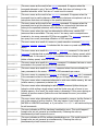
6. Command Types
Many of the Vortex commands have similar formats. The main formats are described here in order to
provide a better understanding of the command set.
6.1. Boolean Commands
Boolean commands take one of the three following arguments.
●
●
●
'0' indicates that the parameter should be turned off.
'1' indicates that the parameter should be turned on.
'2' indicates that the parameter should be toggled (i.e., '0' becomes '1' and '1' becomes '0').
Parameters associated with boolean commands can be queried using the '?' character. For example, if
input A is muted, and you send ' S04MUTEIA? ', the EF2211 will respond with a status message of '
S04MUTEIA1 '. When a status message is generated for a boolean command, the command data will
either be a '0' or '1', since '2' is obviously not a valid state.
6.2. Integer Commands
Integer commands can take one of two types of arguments. The first argument type is absolute,
meaning that the parameter will be set to the specified number. For example, ' S04GAINIA10 '
means that the gain on input A will be set to 10 dB. In this case, the device will respond with a status
message of ' S04GAINIA10 '.
The second argument type is relative, meaning that the parameter will be incremented or
decremented by the specified amount. The increment character is '>' and the decrement character is
'<'. For example, ' S04GAINIA>3 ' increments the gain on input A by 3 dB. If the input's gain was
previously set to 6 dB, then it would now be set to 9 dB. In this case the device would respond with a
status message of ' S04GAINIA9 '.
The numeric part of both the absolute and relative arguments can contain a '+' or '-' to indicate the
algebraic sign of the argument. If no sign is given, '+' is assumed.
The parameters associated with integer commands have maximum and minimum values associated
with them. If you try to set a parameter above its maximum or below its minimum, the parameter will
be set to its maximum or minimum value, respectively.
Parameters associated with integer commands can be queried using the '?' character. For example, if
input A 's gain is set to 12, and you send ' S04GAINIA? ', the device will respond with a status
message of ' S04GAINIA12 '.
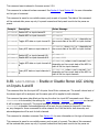
6.3. Channel Commands
A command can be a channel command in addition to being one of the other types of commands
(integer or boolean). A channel command means that the command applies to a specific input or
output channel. The channel is specified by a single character (e.g., '1', 'A', 'B', etc.) occurring before
any other payload data.
An example of a boolean channel command is the 'AGC' (Automatic Gain Control) command. '
S04AGC10 ' disables the AEC on input channel 1 . After sending this command, the device will
respond with a status message of ' S04AGC10 '.
An example of an integer channel command is the 'GAINI' command, which adjusts the gain on the
input channels. ' S04GAINIA12 ' sets the input gain of channel A to 12 dB. After sending this
command, the device will respond with a status message of ' S04GAINIA12 '.
A wildcard character ('*') can be used as the channel specifier for many of the channel commands. If
this is the case, there are two options for specifying the values for the channels. The first method is to
specify a single value that will be applied to all the channels.
Take the MUTEI command for example: ' S04MUTEI*1 ' mutes input channels 1 and A-B After
sending this command, the device will respond with a status message of ' S04MUTEI*111 '. In this
status message, the device reports the status of all the channels. Since the MUTEI command applies
to channels 1 and A-B the status of all 3 channels. The first (left most) value corresponds to channel 1
and the last (right most) value corresponds to channel B.
This leads us to the second method of using a wildcard character: specifying the values for each of
the channels. For example, ' S04MUTEI*101 ' mutes channels 1, B and unmutes channel A. In this
case, the device will respond with a status message of ' S04MUTEI*101 '.
As an interesting example, consider sending ' S04MUTEI*2 ' after the above example. The device will
respond with a status message of ' S04MUTEI*010 '. Notice that all the states have been toggled.
Queries using the '?' character are straightforward. For example, ' S04MUTEI1? ' might return '
S04MUTEI11 ', while ' S04MUTEI*? ' might return ' S04MUTEI*100 '.
Using the wildcard character with integer channel commands is similar to using it with boolean
commands, but there are some differences. If we sent ' S04GAINI*10 ', the input gains on channels
1 and A-B will all be set to 10 dB. The device will respond with a status message of ' S04GAINI*ÄÄÄ
'. Those weird characters are the main difference between using wildcards with integer channel
commands versus boolean channel commands. When reporting multiple integer values, the Vortex
uses a binary format with one byte per integer value. This allows for more compact commands and
reduces RS-232 and bus traffic. To convert from an integer value to a byte value, we add 132 to the
integer value. In the above example, where the gain is set to 10 dB, we have: 10 + 132 = 142 =
0x8E (hex) = Ä (ASCII). The reason for adding 132 is to allow us to conveniently represent negative
numbers as well as avoid the use of special characters that are normally used in RS-232 and EF Bus
communications.
When using a wildcard character to specify separate values for each channel, you must also use the
binary format. For example, ' S04GAINI*Äää ' sets the input gain of channel 1 to 10 dB and the
input gain of channels A-B to 0 dB. (10 + 132 = 142 = 0x8E (hex) = Ä (ASCII), 0 + 132 = 132 =
0x84 (hex) = ä (ASCII))
As an interesting example, consider sending ' S04GAINI*>3 ' after the above example. This will
result in all the input gains being incremented by 3 dB so that channel 1 is at 13 dB and channels A-B
are at 3 dB. The Vortex will respond with a status message of ' S04GAINI*æçç '. (13 + 132 = 145 =
0x91 (hex) = æ (ASCII), 3 + 132 = 135 = 0x87 (hex) = ç (ASCII))
Queries using the '?' character are straightforward. For example, ' S04GAINI1? ' might return '
S04GAINI110 ', while ' S04GAINI*? ' might return ' S04GAINI*Äää '.
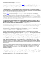
6.4. Matrix Commands
Matrix commands are used for controlling parameters that exist at the crosspoints of the mixing
matrices. Typical parameters include gain and mute. Before describing the matrix commands, it is
necessary to give a description of the matrices involved. During the following discussion, it will be
helpful to refer to the figure below, which shows all the matrices with their input and output labels.
The EF2211 has three analog outputs labeled 1, A, and B. These outputs are all at line level. There
are two additional outputs: the output to the telephone interface, labeled T, and the output to the
power amplifier. The output to the power amplifier does not have a separate output in the matrix, it is
tied to output 1. Thus the signal routed to output 1 will also be routed to the power amplifier output.
This yields a total of four physical outputs.
The EF2211 has three analog inputs labeled 1, A, and B. Input 1 is mic/line selectable, and inputs A-B
are line level only. Input 1 can also have phantom power enabled and contain channel processing,
which includes the following DSP algorithms: Acoustic Echo Cancellation, Noise Cancellation, and AGC.
An additional input, labeled T, comes from the telephone interface. The T input also has signal
processing which includes the following algorithms: Line Echo Cancellation, Noise Cancellation, and
AGC. Inputs 1, A, B, and T yield a total of 4 physical inputs.
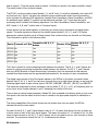
Vortex devices can be linked together so that they can share control information and digital audio
signals. The audio signals are shared on four digital busses labeled P, W, X, Y, and Z. All Vortex
devices can receive signals from all of these busses. Only certain devices can transmit on the busses.
This information is given in the following table.
Device Transmit on P Bus
Transmit on W, X, Y, Z
Busses
Receive P Bus
Receive W, X, Y, Z
Busses
EF2280 No
Yes
Yes
Yes
EF2241 Yes
Yes
Yes
Yes
EF2211 Yes
Yes
Yes
Yes
EF2210 No
Yes
Yes
Yes
EF2201 Yes
No
Yes
Yes
The P bus is meant for routing telephone audio between the devices. The W, X, Y, and Z busses are
meant for routing microphone and auxiliary audio between the devices. The W, X, Y, and Z busses
also carry NOM (Number of Open Microphones) information from the automixer so that outputs
created from these busses can be appropriately attenuated for the number of open microphones.
The digital inputs consist of all of the signals placed on the EF Bus by the other connected Vortex
devices. Each P, W, X, Y, and Z bus can carry channels from up to eight other devices, so we have the
following digital inputs to each Vortex device: PB0-PB7, WB0-WB7, XB0-XB7, YB0-YB7, and ZB0-ZB7.
The inputs are designated by three characters: the bus letter (P, W, X, Y, or Z), a B indicating that it is
a bus input, and a number between 0 and 7 indicating the channel of the bus.
There is also an internal signal generator, labeled SG, that is capable of producing white or pink noise.
this signal is fed into the matrix so that it can be routed to the appropriate outputs for calibration or
testing.
The mixing capabilities of the Vortex devices can be broken down into two parts: the EF Bus
submatrices and the main matrix.
For each of the W, X, Y, and Z signal busses, there is a 7 x 3 matrix that allows the user to define up
to three mixes of each of the four signal busses. The reason the matrix is 7 x 3 instead of 8 x 3 is that
since we can transmit on the W, X, Y, and Z busses, we do not need to mix our own channels in these
matrices. The inputs and outputs for the 7 x 3 matrices are as follows.
W Submatrix
●
●
Inputs: WB0-WB7 (with one invalid)
Outputs: WM0-WM2
X Submatrix
●
●
Inputs: XB0-XB7 (with one invalid)
Outputs: XM0-XM2
Y Submatrix
●
●
Inputs: YB0-YB7 (with one invalid)
Outputs: YM0-YM2
Z Submatrix
●
●
Inputs: ZB0-ZB7 (with one invalid)
Outputs: ZM0-ZM2
For the P signal, bus there is a 7 x 2 matrix that allows the user to define up to two mixes of the P
signal bus. The reason the matrix is 7 x 2 instead of 8 x 2 is that since we can transmit on the P bus,
we do not need to mix our own channels in this matrix. The inputs and outputs for the 7 x 2 P bus
matrix are as follows.
P Submatrix
●
●
Inputs: PB0-PB7 (with one invalid)
Outputs: PM0-PM1
The crosspoint gains on all outputs are user adjustable. The "M" in the output labels of the
submatrices indicates that the signals are being fed into the Main Matrix.
The main matrix consists of the following inputs: analog inputs 1, A, and B, the telephone input T, the
signal generator (SG), the outputs of the EF Bus submatrices PM0-PM1, WM0-WM2, XM0-XM2, YM0YM2, and ZM0-ZM2. This is a total of 19 inputs.
The main matrix consists of the following outputs: analog outputs 1, A, and B, the output to the
telephone interface T, AEC reference signal R1, and the EF bus outputs P, W, X, Y, and Z. This is a
total of 10 outputs.
The matrix commands can adjust two types of parameters: integer and boolean. We will introduce the
matrix commands by using the MGAIN command as an example. This is an integer matrix command
that is used to set the gain (in dB) at any of the crosspoints in the main matrix or EF Bus submatrices.
Matrix commands are similar to channel commands except that instead of specifying a single channel,
it is necessary to specify a crosspoint (or range of crosspoints). In order to specify a single crosspoint,
you use the input and output labels discussed in this section. The first label always specifies the input
to the matrix and the second label always specifies the output of the matrix. For example, to set the
gain of the crosspoint (1, A) to -3 dB, you would send ' S04MGAIN1,A,-3 ' which sets the gain at the
crosspoint to -3 dB. In this case, a status message will be generated similar to ' S04MGAIN1,A,-3 '.
It is also possible to use the wildcard character ('*') to specify ranges of crosspoints with the matrix
commands. The only restriction is that you can only use a wildcard to specify the input or output, but
not both simultaneously. Thus you could specify all the inputs going to a specific output (one column)
or the value of an input to all of the outputs (one row), but not the entire matrix. One example of
using a wildcard for an integer matrix command would be ' S04MGAINSG,*,0 '. This will set all the
crosspoints in the signal generator row of the main matrix to 0 dB. Thus, the signal generator will be
added to all of the outputs of the main matrix with a gain of 0 dB. In this case a status message will
be generated that looks like ' S04MGAINSG,*,ääääääääää '. The binary representation used here is
the same method described in Section 6.3.
You can also use the wildcard character to set the crosspoints of a row or column individually. For
example, 'S04MGAIN1,*,äzzzxxxxxx' sets the crosspoints of input 1 to 0 dB for output 1, -10 dB
for outputs A, B and T, and -12 dB for outputs R1, P, and W-Z. In this case, the EF2211 will respoind
with a status message of 'S04MGAIN1,*,äzzzxxxxxx'.
Queries using the '?' character work in the usual manner. For example, ' S04MGAIN1,A,? ' might
return ' S04MGAIN1,A,-6 ', while ' S04MGAIN1,*,? ' might return ' S04MGAIN2,*,ääääääääää '.
Boolean matrix commands work as you would expect. They use the characters '0', '1', and '2' as
described in Section 6.1. Here are some examples.
●
●
●
●
' S04MMUTE1,A,1 ' mutes crosspoint (1, A) of the main matrix. In other words, the signal at
input 1 will not be heard on output A A status message will be generated of the form '
S04MMUTE1,A,1 '.
'S04MMUTEA,*,1110000000' sets the mutes for input A of the main matrix. The signal path
from input A to outputs 1, A, and B is muted, while the signal path from input A to outputs T,
R1, P, and W-Z is unmuted. The EF2211 will respond with a status message of
'S04MMUTEA,*,1110000000'.
'S04MMUTEA,*,2' toggles the mutes for input A of the main matrix. If this command follows
after the command in the above example, the EF2211 will respond with a status message of
'S04MMUTEA,*,0001111111'.
'S04MMUTEA,*,?' queries the status of the mutes for input A of the main matrix. If this
command follows after the commands in the above examples, the EF2211 will respond with a
status message of 'S04MMUTEA,*,0001111111'.
6.5. Miscellaneous Commands
Miscellaneous commands are those that don't fall under any of the other categories. See the
description of a given command for specific details on how it operates.
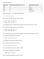
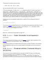
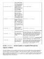
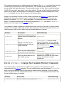
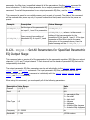
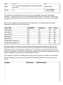
7. Command List
The following table is a list of the commands recognized by the EF2211 Detailed descriptions of each
command are given in the next section.
The Storage column contains one of the following values indicating when and where the parameter is
stored.
●
●
●
"Global"
"Preset"
"-" = not stored or not applicable
Globally stored parameters are not changed when a preset is executed. Only one copy of a global
parameter is stored. Global parameters are written to non-volatile memory each time they are
changed. Globally stored parameters retain their values when the power is cycled.
Parameters stored in presets are changed each time a new preset is restored/executed. Preset
parameters are not saved in non-volatile memory until a PRESETW command is executed. Parameters
stored in the power-on preset (see PRESETP) are restored when the power is cycled.
Command
Storage Description
AA
Preset
Enable or Disable Auto Answer Mode
ACKMOD
Global
Enable or Disable Acknowledgment Mode
AEC
Preset
Enable or Disable Acoustic Echo Cancellation
AECMODE
Preset
Set Amount of Double Talk Suppression used in the AEC.
AGC
Preset
Enable or Disable Mic/Line Input Automatic Gain Control
AGCMAX
Preset
Set Maximum Allowed Mic/Line Input AGC Gain
AGCMIN
Preset
Set Minimum Allowed Mic/Line Input AGC Gain
AGCRATE
Preset
Set Ramp Rate of Mic/Line Input AGC
AHCP
Preset
Enable or Disable Call Progress Based Auto Hangup
AHLD
Preset
Enable or Disable Loop Drop Based Auto Hangup
AMASGN
Preset
Assign Inputs to an Automixer
AMAUTO
Preset
Select Automatic or Manual Gating for each Automixer Input
AMBUSID
Preset
Set Automixer Groupings for EF Bus
AMCHAIR
Preset
Enable Chairman Mode for Specified Automixer
AMCHNUM
Preset
Set Chairman Mic
AMDECAY
Preset
Set Decay Time for Automixers
AMGATEC
Preset
Set Automixer Gating Control Mode
AMGATER
Preset
Set Automixer Gate Ratio
AMGATET
Preset
Set Automixer Gate Threshold
AMGNOM
Preset
Set Global Maximum Number of Open Mics for Bus Automixer
AMHOLD
Preset
Set Automixer Hold Time
AMLMM
Preset
Set Last Mic On Mode for Specified Automixer
AMLMN
Preset
Set Microphone That Will Remain On in Manual Last Mic On Mode
AMNOM
Preset
Set Local Maximum Number of Open Mics for Automixer
AMNOMAT
Preset
Select NOM Attenuation on Each Output
AMOFFAT
Preset
Set Off Attenuation for the Specified Automixer
AMPRIOR
Preset
Set Gating Priority for the Specified Mic
AMREFB
Preset
Set Automixer Reference Bias for the Specified Automixer
AMREFE
Preset
Enable Automixer Reference for Specified Automixer
BAUD
Global
Set Baud Rate for RS-232 Port
BLAUTO
Preset
Enable Automatic BLDATA Messages
BLDATA
-
Request Level Information
BLINFO
Preset
Select Information to be Reported in BLDATA
BROAD2
-
Broadcast Arbitrary Command Strings to RS-232 Port
BROADA
-
Broadcast Commands to Other Connected Devices
BUSREF
Preset
Set Which AEC Reference is Placed on EF Bus
CGATE
-
Query Camera Gating Status Information
CGATEEN
Preset
Enable Automatic Camera Gating Messages
CGATET
Preset
Set Camera Gating Hold Time
COUNTRY
Global
Specify Country Definitions for Phone Interface
DELAYO
Preset
Set Output Delay
DELAYOE
Preset
Enable Output Delay
DIAL
-
Send DTMF Digits to Phone Interface
DSPAUTO
-
Enable Automatic DSPLOAD Status Messages
DSPLOAD
-
Query Percentage of Variable DSP Resources Used
ERROR
Global
Enable or Disable Error Messages
FADERGIL
Preset
Set Fader Gain of Line Inputs as a Group
FADERI
Preset
Set Input Gain Fader
FLASH
-
Execute Hook Flash
FLOW
Global
Set Flow Control Mode for RS-232 Port
FPLOCK
Global
Lock/Unlock Front Panel
FPPSWD
-
Change Front Panel Password
GAINA
Preset
Set Phone Input Gain
GAIND
Preset
Set Gain of Incoming DTMF Tones
GAINDIT
Preset
Set Gain of Incoming DTMF Tones
GAINDT
Preset
Set Dial Tone Gain
GAINGIL
Preset
Set Gain of Line Inputs as a Group
GAINI
Preset
Set Input Gain
GAINO
Preset
Set Output Gain
GAINP
Preset
Set Phone Output Gain
GAINSIT
Preset
Set From Phone User Tone Gain
GAINSOT
Preset
Set To Phone User Tone Gain
GATE
-
Query Gating Status Information
GATEEN
Preset
Enable Automatic Gating Messages
GMUTEO
Preset
Mute All Outputs
ID
Global
Set Device ID
LABEL
Global
Set or Query one of the Device Labels
LAGC
Preset
Enable or Disable Line Input Automatic Gain Control
LAGCLINKAB
Preset
Enable or Disable Stereo AGC Linking on Inputs A and B
LAGCMAX
Preset
Set Maximum Allowed Line Input AGC Gain
LAGCMIN
Preset
Set Minimum Allowed Line Input AGC Gain
LAGCRATE
Preset
Set Ramp Rate of Line Input AGC
LEC
Preset
Enable or Disable LEC
LECMODE
Preset
Set Amount of Double Talk Suppression used in the LEC.
LI
Global
Query State of Logic Inputs
LIA
Global
Assign Action for when Logic Input is Activated
LID
Global
Assign Action for when Logic Input is Deactivated
LIH
Global
Assign Action for when Logic Input is Held
LIEN
Preset
Enable Automatic Logic Input Status Messages
LIG
Global
Configure Logic Input Pins Into a Group
LIK
Global
Delete One or All Logic Input Pin Commands
LIM
Preset
Mask Logic Input Pins
LIN
Global
Assign Command to Logic Input Group
LIP
Global
Set Polarity for Logic Inputs
LO
-
Query or Set Status of Logic Output Pins
LOA
Global
Define Behavior for Logic Output Activated State
LOD
Global
Define Behavior for Logic Output Deactivated Status
LOEN
Preset
Enable Automatic Logic Output Status Messages
LOK
Global
Delete One or All Logic Output Pin Commands
LOM
Preset
Mask Logic Output Pins
LOP
Global
Set Polarity for Logic Outputs
MACROA
-
Add Command to Current Macro
MACROK
Global
Delete One or All Macros
MACROL
-
List All Commmands in a Macro
MACROQ
-
Execute Macro Quietly
MACROS
-
Start a New Macro
MACROW
Global
Write Macro to Non-Volatile Memory
MACROX
-
Execute Macro
METER
Preset
Select which Signal is Displayed on the Front Panel LED Meter
MGAIN
Preset
Set Crosspoint Gains in Main Matrix or Submatrix
MGATE
Preset
Select Gated or Ungated Microphone Signal in Matrix
MIC
Preset
Enable Microphone Gain Stage on Input 1
MINI
Global
Enable Modem Initialization String
MINISTR
Global
Set Modem Initialization String
MMUTE
Preset
Mute Crosspoint in Main Matrix or Submatrix
MUTEGIL
Preset
Set Mute Status of Line Inputs as a Group
MUTEI
Preset
Mute One or More Inputs
MUTEO
Preset
Mute One or More Outputs
NC
Preset
Enable Noise Cancellation
NCL
Preset
Set Noise Cancellation Attenuation
NVINIT
-
Reinitialize Non-Volatile Memory
NVLOCK
Global
Lock/Unlock Non-Volatile Memory
NVPSWD
-
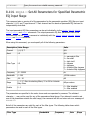
Change Non-Volatile Memory Password
PEQIA
Preset
Set All Parameters for Specified Parametric EQ Input Stage
PEQIB
Preset
Set Bandwidth Parameter for Specified Parametric EQ Input Stage
PEQIE
Preset
Set Enabled Parameter for Specified Parametric EQ Input Stage
PEQIF
Preset
Set Frequency Parameter for Specified Parametric EQ Input Stage
PEQIG
Preset
Set Gain Parameter for Specified Parametric EQ Input Stage
PEQIS
Preset
Set Slope Parameter for Specified Parametric EQ Input Stage
PEQIT
Preset
Set Type Parameter for Specified Parametric EQ Input Stage
PEQOA
Preset
Set All Parameters for Specified Parametric EQ Output Stage
PEQOB
Preset
Set Bandwidth Parameter for Specified Parametric EQ Output Stage
PEQOE
Preset
Set Enabled Parameter for Specified Parametric EQ Output Stage
PEQOF
Preset
Set Frequency Parameter for Specified Parametric EQ Output Stage
PEQOG
Preset
Set Gain Parameter for Specified Parametric EQ Output Stage
PEQOS
Preset
Set Slope Parameter for Specified Parametric EQ Output Stage
PEQOT
Preset
Set Type Parameter for Specified Parametric EQ Output Stage
PHANTOM
Preset
Enable Phantom Power on Input 1
PHONE
-
Take Phone On-Hook or Off-Hook
PING
-
See Which Devices Are Present
PRESETK
Global
Delete One or All Presets
PRESETL
-
List All Commmands in a Preset
PRESETP
Global
Set Which Preset Will Be Activated At Power-Up
PRESETQ
-
Execute a Preset Quietly
PRESETW
Global
Save a Preset
PRESETX
-
Execute a Preset
REDIAL
-
Redial the Last Dialed Phone Number
REFASGN
Preset
Assign AEC Reference to Input Channel
REFGAIN
Preset
Set Reference Output Gain
RING
Preset
Enable or Disable Ring Messages
SGGAIN
Preset
Set Gain of Signal Generator
SGMUTE
Preset
Mute Signal Generator
SGTYPE
Preset
Set Type of Signal Produced by Signal Generator
SOUNDL
-
Play Sound Locally
SOUNDP
-
Play Sound to Phone
SSDELAY
Preset
Set Delay Between Screen Saver Screens
SSEN
Preset
Enable or Disable Screen Saver
SSSTART
Preset
Set Idle Time Required for Screen Saver to Start
SSTEXT
Preset
Set Text to be Displayed by Screen Saver
SWRESET
-
Perform Soft Reset of System
SWVER
-
Query Software Version
TONEE
Preset
Enable or Disable Entry and Exit Tones
TONER
Preset
Enable or Disable Ring Tones
VTXMODI
Preset
Enable VTX Mode on Specified Inputs
VTXMODO
Preset
Enable VTX Mode on Specified Inputs
8. Command Reference
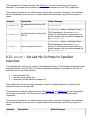
8.1. AA -- Enable or Disable Auto Answer Mode
This command sets or queries the status of the auto answer feature.
This command is a boolean command. See Section 6.1 for more information on this type of command.
This command is saved to non-volatile memory only as part of a preset. The state of this command
will be restored after power-up only if a preset is saved and that preset is set to be the power-on
preset.
Example Description
Status Message
S01AA1
Enable auto answer mode. S01AA1
S01AA0
Disable auto answer mode. S01AA0
S01AA2
Toggle auto answer mode.
S01AAx , where x is 0 or 1 depending on the current state of
auto answer mode.
S01AA?
Query auto answer mode.
S01AAx , where x is 0 or 1 depending on the current state of
auto answer mode.
8.2. ACKMOD -- Enable or Disable Acknowledgment Mode
This command controls whether or not status messages are sent. See Section 5 for more information
on status messages. This parameter is enabled by default, and it is rarely turned off by the host
controller.
This command is a boolean command. See Section 6.1 for more information on this type of command.
This command is saved to global non-volatile memory and is not part of a preset. Its value is saved
each time it is changed. It will retain its value after power-down. Since this command writes to nonvolatile memory, there will be a delay before an acknowledgment is returned.
Example
Description
Status Message
S01ACKMOD1 Enable acknowledgement mode. S01ACKMOD1
S01ACKMOD0 Disable acknowledgement mode. S01ACKMOD0
S01ACKMOD2 Toggle acknowledgement mode.
S01ACKMODx , where x is 0 or 1 depending on the
current state of acknowledgement mode.
S01ACKMOD? Query acknowledgement mode.
S01ACKMODx , where x is 0 or 1 depending on the
current state of acknowledgement mode.
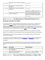
8.3. AEC -- Enable or Disable Acoustic Echo Cancellation
This command sets or queries the status of the Acoustic Echo Cancellation (AEC) algorithm on input
channel 1.
This command is a channel boolean command. See Section 6.3 and Section 6.1 for more information
on this type of command.
This command is saved to non-volatile memory only as part of a preset. The state of this command
will be restored after power-up only if a preset is saved and that preset is set to be the power-on
preset.
Example Description
Status Message
S01AEC11 Enable AEC on input channel 1.
S01AEC11
S01AEC10 Disable AEC on input channel 1.
S01AEC10
S01AEC12 Toggle AEC state on input channel 1.
S01AEC1x , where x is 0 or 1 depending on the
current state of the AEC on input channel 1.
S01AEC1? Query AEC state on input channel 1.
S01AEC1x , where x is 0 or 1 depending on the
current state of the AEC on input channel 1.
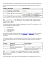
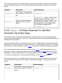
8.4. AECMODE -- Set Amount of Double Talk Suppression
used in the AEC.
This command sets the amount of double talk suppression used in the AEC on input channel 1. The
values correspond to the following settings.
●
●
●
●
1
2
3
4
=
=
=
=
No Suppression
Light Suppression
Heavy Suppression
Half Duplex
This command is a channel integer command. See Section 6.3 and Section 6.2 for more information
on this type of command. The minimum and maximum values for this command are 1 and 4,
respectively.
This command is saved to non-volatile memory only as part of a preset. The state of this command
will be restored after power-up only if a preset is saved and that preset is set to be the power-on
preset.
Example
Description
S01AECMODE13
Set AEC on input channel 1 to Heavy
S01AECMODE13
Suppression.
Query AEC suppression level on
S01AECMODE1?
input channel 1.
Status Message
S01AECMODE1x , where x is 1, 2, 3, or 4
depending on the current setting of the AEC
suppression level on input channel 1.
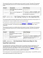
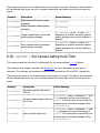
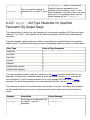
8.5. AGC -- Enable or Disable Mic/Line Input Automatic
Gain Control
This command sets or queries the status of the Automatic Gain Control (AGC) algorithm on input
channels 1 and T (the telephone input) .
Using the wildcard character, '*', to specify the channel with this command is not supported for the
EF2211. To set or query the command, the channels must be specified explicitly (e.g., 'S01AGC1?',
'S01AGCT0').
This command is a channel boolean command. See Section 6.3 and Section 6.1 for more information
on this type of command.
This command is saved to non-volatile memory only as part of a preset. The state of this command
will be restored after power-up only if a preset is saved and that preset is set to be the power-on
preset.
Example Description
Status Message
S01AGC11 Enable AGC on input channel 1 .
S01AGC11
S01AGCT0 Disable AGC on input channel T .
S01AGCT0
S01AGC12 Toggle AGC state on input channel 1 .
S01AGC1x , where x is 0 or 1 depending on the
current state of the AGC on input channel 1 .
S01AGCT? Query AGC state on input channel T .
S01AGCTx , where x is 0 or 1 depending on the
current state of the AGC on input channel T .
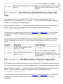
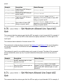
8.6. AGCMAX -- Set Maximum Allowed Mic/Line Input AGC
Gain
This command sets the maximum gain that the AGC can apply on input channels 1 and T (the
telephone input) . For example, if AGCMAX is set to 10, then the AGC for that channel can apply a
maximum of 10 dB of gain to the input signal.
Using the wildcard character, '*', to specify the channel with this command is not supported for the
EF2211. To set or query the command, the channels must be specified explicitly (e.g.,
'S01AGCMAX1?', 'S01AGCMAXT7').
This command is a channel integer command. See Section 6.3 and Section 6.2 for more information
on this type of command. The minimum and maximum values for this command are 0 and 15,
respectively.
This command is saved to non-volatile memory only as part of a preset. The state of this command
will be restored after power-up only if a preset is saved and that preset is set to be the power-on
preset.
Example
Description
Status Message
S01AGCMAX13
Set AGC maximum gain on input
channel 1 to 3 dB.
S01AGCMAX13
S01AGCMAXTx where x is a number
Query the AGC maximum gain on input between 0 and 15, depending on the current
S01AGCMAXT?
channel T .
setting of the AGC maximum gain on input
channel T .
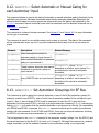
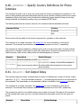
8.7. AGCMIN -- Set Minimum Allowed Mic/Line Input AGC
Gain
This command sets the minimum gain that the AGC can apply on input channels 1 and T (the
telephone input) . For example, if AGCMIN is set to -10, then the AGC for that channel can apply a
minimum of -10 dB of gain to the input signal.
Using the wildcard character, '*', to specify the channel with this command is not supported for the
EF2211. To set or query the command, the channels must be specified explicitly (e.g.,
'S01AGCMIN1?', 'S01AGCMINT-7').
This command is a channel integer command. See Section 6.3 and Section 6.2 for more information
on this type of command. The minimum and maximum values for this command are -15 and 0,
respectively.
This command is saved to non-volatile memory only as part of a preset. The state of this command
will be restored after power-up only if a preset is saved and that preset is set to be the power-on
preset.
Example
Description
Status Message
S01AGCMIN1-3
Set AGC minimum gain on input
channel 1 to -3 dB.
S01AGCMIN1-3
Query the AGC minimum gain on
input channel T .
S01AGCMINTx where x is a number
between -15 and 0, depending on the
current setting of the AGC minimum gain on
input channel T .
S01AGCMINT?
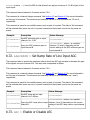
8.8. AGCRATE -- Set Ramp Rate of Mic/Line Input AGC
This command sets or queries the maximum rate at which the AGC can increase or decrease the gain
of the signals on input channels 1 and T (the telephone input) . The ramp rate is expressed in dB/sec.
Using the wildcard character, '*', to specify the channel with this command is not supported for the
EF2211. To set or query the command, the channels must be specified explicitly (e.g.,
'S01AGCRATE1?', 'S01AGCRATET3').
This command is a channel integer command. See Section 6.3 and Section 6.2 for more information
on this type of command. The minimum and maximum values for this command are 1 and 5,
respectively.
This command is saved to non-volatile memory only as part of a preset. The state of this command
will be restored after power-up only if a preset is saved and that preset is set to be the power-on
preset.
Example
Description
S01AGCRATE13
Set AGC ramp rate on input channel
S01AGCRATE13
1 to 3 dB/sec.
S01AGCRATET?
Query the AGC ramp rate on input
channel T .
Status Message
S01AGCRATETx where x is a number
between 1 and 5, depending on the current
setting of the AGC ramp rate on input
channel T .
8.9. AHCP -- Enable or Disable Call Progress Based Auto
Hangup
This command sets or queries the status of the call progress based auto hangup feature. There are
two methods of auto hangup supported: call progress and loop drop. The call progress method listens
for off-hook or busy tones and hangs up the phone if they are detected. The loop drop method looks
for a drop in loop current on the phone line and hangs up the phone if a loop current drop is detected.
The AHCP command controls the call progress auto hangup feature. The AHLD command controls the
loop drop auto hangup feature. These two features are controlled and implemented independently.
This command is a boolean command. See Section 6.1 for more information on this type of command.
This command is saved to non-volatile memory only as part of a preset. The state of this command
will be restored after power-up only if a preset is saved and that preset is set to be the power-on
preset.
Example Description
Status Message
S01AHCP1 Enable call progress based auto hangup mode. S01AHCP1
S01AHCP0 Disable call progress based auto hangup mode. S01AHCP0
S01AHCPx , where x is 0 or 1
S01AHCP2 Toggle call progress based auto hangup mode. depending on the current state of the
call progress based auto hangup mode.
S01AHCP? Query auto hangup mode.
S01AHCPx , where x is 0 or 1
depending on the current state of the
call progress based auto hangup mode.
8.10. AHLD -- Enable or Disable Loop Drop Based Auto
Hangup
This command sets or queries the status of the loop drop based auto hangup feature. There are two
methods of auto hangup supported: call progress and loop drop. The call progress method listens for
off-hook or busy tones and hangs up the phone if they are detected. The loop drop method looks for
a drop in loop current on the phone line and hangs up the phone if a loop current drop is detected.
The AHCP command controls the call progress auto hangup feature. The AHLD command controls the
loop drop auto hangup feature. These two features are controlled and implemented independently.
This command is a boolean command. See Section 6.1 for more information on this type of command.
This command is saved to non-volatile memory only as part of a preset. The state of this command
will be restored after power-up only if a preset is saved and that preset is set to be the power-on
preset.
Example Description
Status Message
S01AHLD1 Enable loop drop based auto hangup mode. S01AHLD1
S01AHLD0 Disable loop drop based auto hangup mode. S01AHLD0
S01AHLDx , where x is 0 or 1 depending
S01AHLD2 Toggle loop drop based auto hangup mode. on the current state of the loop drop based
auto hangup mode.
S01AHLD? Query auto hangup mode.
S01AHLDx , where x is 0 or 1 depending
on the current state of the loop drop based
auto hangup mode.
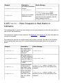
8.11. AMASGN -- Assign Inputs to an Automixer
This command is used to assign the mic/line inputs (1) to an internal automixers. Setting AMASGN to 0
for a given input channel corresponds to no automixer, and 1 corresponds to Automixer #1 .
Although this command is a channel integer command, the increment and decrement operators (>
and <) are not supported for this particular command.
This command is a channel integer command. See Section 6.3 and Section 6.2 for more information
on this type of command. The minimum and maximum values for this command are 0 and 2,
respectively.
This command is saved to non-volatile memory only as part of a preset. The state of this command
will be restored after power-up only if a preset is saved and that preset is set to be the power-on
preset.
Example
Description
S01AMASGN11 Assign input 1 to automixer #1.
S01AMASGN1?
Query current automixer assignment
for channel 1.
Status Message
S01AMASGN11
S01AMASGN1x , where x is 0, 1, or 2
depending on the current automixer
assignment for channel 1. If this command
is issued after the example above, then the
status message will be S01AMASGN11 .
8.12. AMAUTO -- Select Automatic or Manual Gating for
each Automixer Input
This command selects or queries the state of automatic or manual automixer gating thresholds for the
specified input channel. Automatic thresholds mean that the automixer adaptively determines the
gating thresholds based on current speech and noise levels using the gating ratio specified by the
AMGATER command. Manual thresholds mean that the automixer uses the absolute threshold set via
the AMGATET command.
This command is a channel boolean command. See Section 6.3 and Section 6.1 for more information
on this type of command.
This command is saved to non-volatile memory only as part of a preset. The state of this command
will be restored after power-up only if a preset is saved and that preset is set to be the power-on
preset.
Example
Description
Status Message
S01AMAUTO11
Select automatic thresholds for
automixer gating on input channel 1.
S01AMAUTO11
S01AMAUTO10
Select manual thresholds for automixer
S01AMAUTO10
gating on input channel 1.
S01AMAUTO1x , where x is 0 or 1
Toggle between automatic and manual
depending on whether input channel 1 is
S01AMAUTO12 thresholds for automixer gating on
currently set for manual or automatic
input channel 1.
thresholds.
S01AMAUTO1x , where x is 0 or 1
Query AMAUTO state on input channel depending on whether input channel 1 is
S01AMAUTO1?
1.
currently set for manual or automatic
thresholds.
8.13. AMBUSID -- Set Automixer Groupings for EF Bus
This command is used to assign the internal automixer to one of the EF Bus automixer groups. For
example, consider three EF2211's, each of which has its automixer enabled for its microphone input
(input 1). Now, if each of these EF2211's sets its automixer to have Bus ID 5, then the three
automixers (one from each EF2211) will work as a single automixer containing 3 (3 x 1) microphones.
Setting AMBUSID to 0 means that the specified automixer is not grouped on the bus. For compatibility
with EF2280 and EF2241 commands, the AMBUSID command requires you to specify the automixer
number with the command. On the EF2280 and EF2241, there are two internal automixers. However,
the EF2211 only has one internal automixer, so 1 is always specified.
The first argument in the AMBUSID command is the automixer number (always 1 for the EF2211) and
the second argument is the Bus ID (0 for none, or 1 through 8). Although this command is a channel
integer command, use of the wildcard character for the automixer number is not supported.
This command is a channel integer command. See Section 6.3 and Section 6.2 for more information
on this type of command. The minimum and maximum values for this command are 0 and 8,
respectively.
This command is saved to non-volatile memory only as part of a preset. The state of this command
will be restored after power-up only if a preset is saved and that preset is set to be the power-on
preset.
Example
Description
Status Message
Configure the automixer to be part
S01AMBUSID12 of the Bus Automixer having Bus ID S01AMBUSID12
2.
Configure the automixer to be part
of the Bus Automixer having Bus D
S01AMBUSID10
0. This means that the automixer is
not part of any Bus Automixer.
S01AMBUSID10
Query the current Bus ID of the
S01AMBUSID1?
automixer.
S01AMBUSID1x , where x is a number
between 0 and 8 indicating the current Bus
ID of the automixer.
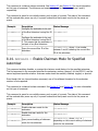
8.14. AMCHAIR -- Enable Chairman Mode for Specified
Automixer
This command enables, disables, or queries the chairman mode feature for the specified automixer.
The first argument in the command specifies the automixer number (always 1 for the EF2211) and the
second argument specifies whether chairman mode should be enabled, disabled, toggled, or queried.
Even though this is a channel boolean command, use of the wildcard character for the automixer
number is not supported.
This command is a channel boolean command. See Section 6.3 and Section 6.1 for more information
on this type of command.
This command is saved to non-volatile memory only as part of a preset. The state of this command
will be restored after power-up only if a preset is saved and that preset is set to be the power-on
preset.
Example
Description
Status Message
S01AMCHAIR10
Disable chairman mode for the
automixer.
S01AMCHAIR10
S01AMCHAIR11
Enable chairman mode for the
automixer.
S01AMCHAIR11
S01AMCHAIR1?
Query current setting of chairman
mode for the automixer.
S01AMCHAIR1x , where x is 0 or 1
depending on the current setting of chairman
mode for the automixer.
8.15. AMCHNUM -- Set Chairman Mic
This command sets the chairman microphone for the automixer. The first argument of the command
specifies the automixer number (always 1 for the EF2211) . The second argument specifies which
microphone should be the chairman microphone for the automixer (always 1 for the EF2211) . This
command is not particularly useful on the EF2211 and EF2210, however it is provided for consistency
with the EF2280 and EF2241.
Even though this is a channel integer command, use of the wildcard character for the automixer
number is not supported.
This command is a channel integer command. See Section 6.3 and Section 6.2 for more information
on this type of command. The minimum and maximum values for this command are 1 and 1,
respectively.
This command is saved to non-volatile memory only as part of a preset. The state of this command
will be restored after power-up only if a preset is saved and that preset is set to be the power-on
preset.
Example
Description
Status Message
S01AMCHNUM11
Set microphone 1 as the chairman
mic for the automixer.
S01AMCHNUM11
Query the current chairman mic for
S01AMCHNUM1?
the automixer.
S01AMCHNUM11 , querying the chairman mic
number will always return 1 since there is
only one microphone on the EF2211 .
8.16. AMDECAY -- Set Decay Time for Automixers
This command sets or queries the decay time (in milliseconds) for the automixer.
This command is an integer command. See Section 6.2 for more information on this type of
command. The minimum and maximum values for this command are 0 and 5000, respectively.
This command is saved to non-volatile memory only as part of a preset. The state of this command
will be restored after power-up only if a preset is saved and that preset is set to be the power-on
preset.
Example
Description
Status Message
S01AMDECAY500
Set automixer decay time to 500
S01AMDECAY500
ms.
S01AMDECAY>500
S01AMDECAY?
Increase automixer decay time
by 500 ms.
S01AMDECAYx , where x is between 0 and
5000 depending on the current AMDECAY
setting. If this command is issued after the
above example, then the status message will
be
Query automixer decay time.
S01AMDECAYx , where x is between 0 and
5000 depending on the current AMDECAY
setting. If this command is issued after the
above example, then the status message will
be S01AMDECAY1000
8.17. AMGATEC -- Set Automixer Gating Control Mode
This command sets the automixer gating control mode for the specified input channel. The possible
modes are:
●
●
●
0 - normal gating
1 - microphone forced on
2 - microphone forced off
This command is a channel integer command. See Section 6.3 and Section 6.2 for more information
on this type of command. The minimum and maximum values for this command are 0 and 2,
respectively.
This command is saved to non-volatile memory only as part of a preset. The state of this command
will be restored after power-up only if a preset is saved and that preset is set to be the power-on
preset.
Example
Description
Status Message
S01AMGATEC10
Configure microphone input 1 for
normal gating.
S01AMGATEC10
S01AMGATEC11
Configure microphone input 1 to be
forced on.
S01AMGATEC11
S01AMGATEC12
Configure microphone input 1 to be
forced off.
S01AMGATEC12
S01AMGATEC1?
Query current gating control mode
for microphone input 1.
S01AMGATEC3x , where x is 0, 1, or 2
depending on the current gating control
mode setting for microphone input 1.
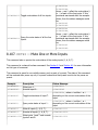
8.18. AMGATER -- Set Automixer Gate Ratio
This command sets the automixer gate ratio (in dB) for the specified input channel. The gate ratio is
the ratio of the speech power to noise power required to gate the microphone on. This value is only
used if the input is set to automatic gating via the AMAUTO.
This command is a channel integer command. See Section 6.3 and Section 6.2 for more information
on this type of command. The minimum and maximum values for this command are 0 and 100,
respectively.
This command is saved to non-volatile memory only as part of a preset. The state of this command
will be restored after power-up only if a preset is saved and that preset is set to be the power-on
preset.
Example
Description
Status Message
Set gate ratio for automatic gating
S01AMGATER112 threshold to 12 dB for input
S01AMGATER112
channel 1.
S01AMGATER1x , where x is between 0 and
100 depending on the current setting of the
Increase gate ratio for automatic
S01AMGATER1>3 gating threshold by 3 dB for input gate ratio for input channel 1. If this
command is issued after the example above,
channel 1.
then the status message will be
S01AMGATER115 .
S01AMGATER1?
S01AMGATER1x , where x is between 0 and
100 depending on the current setting of the
Query gate ratio for automatic
gate ratio for input channel 1. If this
gating threshold for input channel
command is issued after the example above,
1.
then the status message will be
S01AMGATER115 .
8.19. AMGATET -- Set Automixer Gate Threshold
This command sets the automixer gate threshold (in dB) for the specified input channel. The gate
threshold is the level that the input signal must reach in order to gate the microphone on. This value
us only used if the input is set to manual gating via the AMAUTO command.
This command is a channel integer command. See Section 6.3 and Section 6.2 for more information
on this type of command. The minimum and maximum values for this command are 0 and 100,
respectively.
This command is saved to non-volatile memory only as part of a preset. The state of this command
will be restored after power-up only if a preset is saved and that preset is set to be the power-on
preset.
Example
Description
Status Message
Set gate threshold for manual
S01AMGATET112 gating threshold to 12 dB for input S01AMGATET112
channel 1.
Increase gate threshold for
S01AMGATET1>3 manual gating threshold by 3 dB
for input channel 1.
S01AMGATET1?
S01AMGATET1x , where x is between 0 and
100 depending on the current setting of the
gate threshold for input channel 1. If this
command is issued after the example above,
then the status message will be
S01AMGATET315 .
S01AMGATET1x , where x is between 0 and
100 depending on the current setting of the
Query gate threshold for manual
gate threshold for input channel 1. If this
gating threshold for input channel
command is issued after the example above,
1.
then the status message will be
S01AMGATET115 .
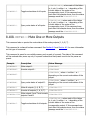
8.20. AMGNOM -- Set Global Maximum Number of Open Mics
for Bus Automixer
This command sets the global maximum number of open mics (NOM) allowed for the specified bus
automixer. The NOM limit is a global limit, meaning that this applies to all bus automixers with the
same AMBUSID. In contrast, the AMNOM command is a local limit that applies to the local automixer in
the EF2211.
The first argument of this command specifies the automixer number (always 1 in the EF2211) to
adjust. The second argument specifies the NOM limit (1-64). Even though this is a channel integer
command, use of the wildcard for specifying the automixer number is not supported.
This command is a channel integer command. See Section 6.3 and Section 6.2 for more information
on this type of command. The minimum and maximum values for this command are 1 and 64,
respectively.
This command is saved to non-volatile memory only as part of a preset. The state of this command
will be restored after power-up only if a preset is saved and that preset is set to be the power-on
preset.
Example
Description
Status Message
S01AMGNOM13
Set global NOM for the automixer to a
S01AMGNOM13
maximum of 3 mics.
S01AMGNOM1?
S01AMGNOM1x , where x is between 1 and
Query current global NOM limit for the
64 depending on the current setting of the
automixer.
global NOM limit for the automixer.
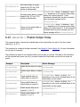
8.21. AMHOLD -- Set Automixer Hold Time
This command sets or queries the hold time (in milliseconds) for the automixer.
This command is an integer command. See Section 6.2 for more information on this type of
command. The minimum and maximum values for this command are 0 and 5000, respectively.
This command is saved to non-volatile memory only as part of a preset. The state of this command
will be restored after power-up only if a preset is saved and that preset is set to be the power-on
preset.
Example
Description
Status Message
S01AMHOLD500
Set automixer hold time to 500
ms.
S01AMHOLD500
Increase automixer hold time by
500 ms.
S01AMHOLDx , where x is between 0 and
5000 depending on the current AMHOLD
setting. If this command is issued after the
above example, then the status message will
be S01AMHOLD1000
Query automixer hold time.
S01AMHOLDx , where x is between 0 and
5000 depending on the current AMHOLD
setting. If this command is issued after the
above example, then the status message will
be S01AMHOLD1000
S01AMHOLD>500
S01AMHOLD?
8.22. AMLMM -- Set Last Mic On Mode for Specified
Automixer
This command sets "last mic on" mode for the specified automixer. The first argument specifies which
automixer (always 1 on the EF2211) The second parameter specifies the operation of "last mic on"
mode and can be one of the following:
●
●
●
0 - last mic mode is off
1 - manual (use a specific mic)
2 - automatic (the last gated mic remains on)
Even though this is a channel integer command, use of the wildcard character for specifying the
automixer number is not supported.
This command is a channel integer command. See Section 6.3 and Section 6.2 for more information
on this type of command. The minimum and maximum values for this command are 0 and 2,
respectively.
This command is saved to non-volatile memory only as part of a preset. The state of this command
will be restored after power-up only if a preset is saved and that preset is set to be the power-on
preset.
Example
Description
Status Message
S01AMLMM10
Disable "last mic on" mode for automixer
S01AMLMM10
1.
S01AMLMM11
Set "last mic on" mode to manual for
automixer 1.
S01AMLMM11
S01AMLMM12
Set "last mic on" mode to automatic for
automixer 1.
S01AMLMM12
S01AMLMM1x , where x is 0, 1, or 2
depending on the current setting of "last
Query the current setting of "last mic on" mic on" mode for automixer 1. If this
S01AMLMM1?
mode for automixer 1.
command is issued after the example
above, then the status message will be
S01AMLMM12 .
8.23. AMLMN -- Set Microphone That Will Remain On in
Manual Last Mic On Mode
This command sets the microphone number that will remain on when "last mic on" mode is set to
manual (see the AMLMM command). The first argument to this command is the number of the
automixer (always 1 on the EF2211) that will be adjusted. The second argument is the microphone
number (always 1) that should be gated on if no other mics are gated on and AMLMM is set to manual.
The value of the AMLMN command is only valid when AMLMM is set to manual.
This command is not particularly useful on the EF2211 since there is only one mic on this device.
However, it is provided in order to be consistent with the command sets of the other Vortex devices.
Even though this is a channel integer command, use of the wildcard character for the automixer
number is not supported.
This command is a channel integer command. See Section 6.3 and Section 6.2 for more information
on this type of command. The minimum and maximum values for this command are 1 and 8,
respectively.
This command is saved to non-volatile memory only as part of a preset. The state of this command
will be restored after power-up only if a preset is saved and that preset is set to be the power-on
preset.
Example
Description
Status Message
S01AMLMN11
Set microphone 1 as the manual last mic
S01AMLMN11
on for automixer 1.
S01AMLMN1?
Query the current manual last mic on
number mic for automixer 1.
S01AMLMN1x , where x is always 1, since
there is only 1 mic on this device.
8.24. AMNOM -- Set Local Maximum Number of Open Mics
for Automixer
This command sets the local maximum number of open mics (NOM) allowed for the specified
automixer. The NOM limit is a local limit, meaning that this limit applies only to the specific Vortex that
is is set on. In contrast, the AMGNOM command is a global limit that applies to all linked Vortex
automixers with the same AMBUSID.
The first argument of this command specifies the automixer number (always 1 on the EF2211) to
adjust. The second argument specifies the NOM limit (always 1). Even though this is a channel integer
command, use of the wildcard for specifying the automixer number is not supported.
This command is not particularly useful on the EF2211 since there is only one mic on this device.
However, it is provided in order to be consistent with the command sets of the other Vortex devices.
This command is a channel integer command. See Section 6.3 and Section 6.2 for more information
on this type of command. The minimum and maximum values for this command are 1 and 64,
respectively.
This command is saved to non-volatile memory only as part of a preset. The state of this command
will be restored after power-up only if a preset is saved and that preset is set to be the power-on
preset.
Example
Description
Status Message
S01AMNOM11
Set local NOM for automixer 1 to a
maximum of 1 mics.
S01AMNOM11
S01AMNOM1?
Query current local NOM limit for
automixer 1.
S01AMNOM1x , where x is always 1, since
there is only 1 mic on this device.
8.25. AMNOMAT -- Select NOM Attenuation on Each Output
This command enables, disables, or queries NOM attenuation for the specified output (1, A, B, T) . .
NOM attenuation is calculated as 10*log(Number of Open Microphones).
Remember that even though there is only one microphone on this device, other microphones can be
brought in via the W, X, Y, and Z busses. These signals will have NOM information carried with them
from the other devices, which is why NOM attenuation is provided at the outputs.
This command is a channel boolean command. See Section 6.3 and Section 6.1 for more information
on this type of command.
This command is saved to non-volatile memory only as part of a preset. The state of this command
will be restored after power-up only if a preset is saved and that preset is set to be the power-on
preset.
Example
Description
Status Message
S01AMNOMAT11
Enable NOM attenuation on
output 1 .
S01AMNOMAT11
S01AMNOMATA0
Disable NOM attenuation on
output A.
S01AMNOMATA0
S01AMNOMATT2
S01AMNOMATTx , where x is either 0 or 1
Toggle NOM attenuation
status on output T (telephone depending on the current mute status of NOM
output) .
attenuation on the ouptut.
S01AMNOMATB?
S01AMNOMATBx , where x is either 0 or 1
Query NOM attenuation status
depending on the current NOM attenuation
of output B.
status of the output.
S01AMNOMAT*1
Enable NOM attenuation on all
S01AMNOMAT*1111
outputs (1, A, B, T) .
S01AMNOMAT*0
Disable NOM attenuation on
all outputs (1, A, B, T) .
S01AMNOMAT*0000
Enable NOM attenuation on
outputs 1 and A, and disable
S01AMNOMAT*1100
S01AMNOMAT*1100
NOM attenuation on outputs B
and T.
S01AMNOMAT*abcd , where each of the letters
(a, b, etc.) is either 0 or 1 depending of the
current status of NOM attenuation on the
corresponding output. If this command was
sent after the example above, then the status
message would be S01AMNOMAT*0011 .
S01AMNOMAT*2
Toggle status of NOM
attenuation on all outputs.
S01AMNOMAT*?
S01AMNOMAT*abcd , where each of the letters
(a, b, etc.) is either 0 or 1 depending of the
Query NOM attenuation status current status of the NOM attenuation on the
of all outputs.
corresponding output. If this command was
sent after the example above, then the status
message would be S01AMNOMAT*0011 .
8.26. AMOFFAT -- Set Off Attenuation for the Specified
Automixer
This command sets the off attenuation (in dB) for the specified automixer. Setting this value to 18
would result in the microphone signals being attenuated by 18 dB when gated off. This value is set
independently for each of the automixers. The first argument of this command specifies the automixer
number (1-2) to adjust. The second argument specifies the off attenuation.
Even though this is a channel integer command, use of the wildcard for specifying the automixer
number is not supported.
This command is a channel integer command. See Section 6.3 and Section 6.2 for more information
on this type of command. The minimum and maximum values for this command are 1 and 100,
respectively.
This command is saved to non-volatile memory only as part of a preset. The state of this command
will be restored after power-up only if a preset is saved and that preset is set to be the power-on
preset.
Example
Description
Status Message
S01AMOFFAT118
Set off attenuation for automixer
1 to 18 dB.
S01AMOFFAT118
S01AMOFFAT1?
Query current off attenuation for
automixer 1.
S01AMOFFAT1x , where x is between 1 and
100 depending on the current setting of the
off attenuation for automixer 1.
8.27. AMPRIOR -- Set Gating Priority for the Specified Mic
This command sets the automixer gating priority for the specified input channel. Priority levels of 1-4
are allowed with 1 being the highest priority and 4 being the lowest.
This command is a channel integer command. See Section 6.3 and Section 6.2 for more information
on this type of command. The minimum and maximum values for this command are 1 and 4,
respectively.
This command is saved to non-volatile memory only as part of a preset. The state of this command
will be restored after power-up only if a preset is saved and that preset is set to be the power-on
preset.
Example
Description
Status Message
S01AMPRIOR11
Set microphone input 1 to gating
priority 1.
S01AMPRIOR11
S01AMPRIOR1?
Query current gating priority for
microphone input . 1.
S01AMPRIOR1x , where x is between 1 and
4 depending on the current gating priority
setting for microphone input . 1.
8.28. AMREFB -- Set Automixer Reference Bias for the
Specified Automixer
This command sets or queries the reference bias for the automixer reference mode feature of the
specified automixer. When enabled, the automixer reference feature uses the AEC reference to
prevent local microphones from gating on audio from the remote side. The AMREFE command controls
the enabled status of this feature. The AMREFB command can be used to bias the AEC reference
signal to make the automixer even less likely to gate on remote audio.
The first argument in this command specifies the automixer number (always 1 on the EF2211) and the
second argument specifies the reference bias in dB.
Even though this is a channel integer command, use of the wildcard character for the automixer
number is not supported.
This command is a channel integer command. See Section 6.3 and Section 6.2 for more information
on this type of command. The minimum and maximum values for this command are 0 and 20,
respectively.
This command is saved to non-volatile memory only as part of a preset. The state of this command
will be restored after power-up only if a preset is saved and that preset is set to be the power-on
preset.
Example
Description
S01AMREFB16
Set reference bias for automixer 1 to 6
S01AMREFB16
dB.
Query current reference bias for
S01AMREFB1?
automixer 1.
Status Message
S01AMREFB1x , where x is between 0 and
20 depending on the current setting of the
reference bias for automixer 1.
8.29. AMREFE -- Enable Automixer Reference for Specified
Automixer
This command enables, disables, or queries the automixer referece feature for the specified
automixer. When enabled, the automixer reference feature uses the AEC reference to prevent local
microphones from gating on audio from the remote side. The AMREFE command controls the enabled
status of this feature. The AMREFB command can be used to bias the AEC reference signal to make
the automixer even less likely to gate on remote audio.
The first argument in the command specifies the automixer number (always 1 on the EF2211) and the
second argument specifies whether automixer reference mode should be enabled, disabled, toggled,
or queried.
Even though this is a channel boolean command, use of the wildcard character for the automixer
number is not supported.
This command is a channel boolean command. See Section 6.3 and Section 6.1 for more information
on this type of command.
This command is saved to non-volatile memory only as part of a preset. The state of this command
will be restored after power-up only if a preset is saved and that preset is set to be the power-on
preset.
Example
Description
Status Message
S01AMREFE10
Disable automixer reference mode for
Automixer 1.
S01AMREFE10
S01AMREFE11
Enable automixer reference mode for
Automixer 1.
Query current setting of automixer
S01AMREFE1?
reference mode for Automixer 1.
S01AMREFE11
S01AMREFE1x , where x is 0 or 1
depending on the current setting of
automixer reference mode for Automixer 1.
8.30. BAUD -- Set Baud Rate for RS-232 Port
This command sets the baud rate for the rear panel RS-232 port. The baud rate is specified in bits per
second (bps). Valid baud rates are 9600, 19200, and 38400. Although, this command returns an
acknowledgement, it is likely that you will not receive it, since it is sent at the new baud rate. If you
setup your control system to quickly change its RS-232 baud rate after you send this command, then
you can probably receive the acknowledgement at the new baud rate.
This command is saved to global non-volatile memory and is not part of a preset. Its value is saved
each time it is changed. It will retain its value after power-down. Since this command writes to nonvolatile memory, there will be a delay before an acknowledgment is returned.
Example
Description
Status Message
S01BAUD38400
Set baud rate of rear panel RS-232
port to 38400 bps.
S01BAUD38400
S01BAUD?
Query current baud rate of rear
panel RS-232 port.
S01BAUDx , where x is 9600, 19200, or
38400 depending on the current baud rate
setting.
8.31. BLAUTO -- Enable Automatic BLDATA Messages
This command sets whether or not BLDATA messages are automatically generated by the Vortex. See
the BLDATA command for more information.
This command is a boolean command. See Section 6.1 for more information on this type of command.
This command is saved to non-volatile memory only as part of a preset. The state of this command
will be restored after power-up only if a preset is saved and that preset is set to be the power-on
preset.
Example
Description
Status Message
S01BLAUTO0 Disable automatic BLDATA messages.
S01BLAUTO0
S01BLAUTO1 Enable automatic BLDATA messages.
S01BLAUTO1
S01BLAUTO2
Toggle enabled status of automatic
BLDATA messages.
S01BLAUTOx , where x is 0 or 1
depending on the current setting of
BLAUTO.
S01BLAUTO?
Query enabled status of automatic
BLDATA messages.
S01BLAUTOx , where x is 0 or 1
depending on the current setting of
BLAUTO.
8.32. BLDATA -- Request Level Information
This command is used to request "blinking light" data from the EF2211. Blinking light data consists of
signal levels for the 5 inputs (1, A, B, T), 4 outputs (1, A, B, T, L), and AEC reference (R1) as well as
the room gain level for input 1, AGC gain level for input 1, and AEC state information for input 1.
The blinking light data can be received in two ways. The first way is by polling the Vortex by sending
a BLDATA? command. The second way is to have the Vortex automatically send BLDATA responses
via the BLAUTO command.
The most general format of the BLDATA responses generated by the Vortex is as follows.
S01BLDATAiiiiooooorgas
Each of the i, o, r, g, a and s characters above represents a single byte of data as shown in the
table below.
BLDATA Bytes
Meaning
iiii
input levels 1, A, B, T
ooooo
output levels 1, A, B, T, L
r
AEC reference level R1
g
room gain 1
a
AGC gain 1
s
AEC state 1
Each of the i bytes correspond to signal levels on the 4 inputs in the following order (from left to
right): 1, A, B, T. The o bytes correspond to signal levels on the 5 outputs in the following order (from
left to right): 1, A, B, T, L. The r byte indicates the signal level for AEC reference R1. The the g byte
indicates the room gain for input 1. The a byte indicates the AGC gain on input 1. The s byte indicates
the AEC state for input 1.
The formats of the i, o, r, g, and a bytes are the same as for the binary gain commands (binary
values offset by 132). See Section 6.3 and Section 6.4 for more information on the binary format.
The range for the i and o bytes is -100 dB to +20 dB, which corresponds to byte values of 32 to 152.
For reference, the LEDs on the front panel signal meter correspond to teh following dB levels (left to
right): -20, -12, -7, -3, 0, 3, 9, 20.
The format of the s bytes are also the same as the binary gain commands. The bytes are integers
(offset by 132) that represent the current AEC state. The following table shows how the byte values
translate to AEC states.
Byte Value
AEC State Value (Byte Value - 132)
AEC State Description
132
0
Idle
133
1
Transmit
134
2
Receive
135
3
Double Talk
Here's an example BLDATA message to clear things up.
S01BLDATApèppçppppppèä
The first four bytes (pèpp) consist of only two values.
p = 0x70 = 112 → 112 - 132 = -20
è = 0x8A = 138 → 138 - 132 = 6
So, the signal at input A is at 6 dB, while the signals at the rest of the inputs are at -20 dB.
The next five bytes (çpppp) consist of only two values.
p = 0x70 = 112 → 112 - 132 = -20
ç = 0x87 = 135 → 135 - 132 = 3
So, the signal at output 1 is at 3 dB, while the signals at the rest of the outputs are at -20 dB.
The next byte (p) consists of only one value.
p = 0x70 = 112 → 112 - 132 = -20
So, the signal level of the AEC reference is -20 dB.
The next byte (p) consists of only one value.
p = 0x70 = 112 → 112 - 132 = -20
So, we know that the room gain for input 1 is -20 dB.
The next byte (è) consists of only one value.
è = 0x8A = 138 → 138 - 132 = 6
So, we know that the AGC gain for input1 1 is 6 dB.
The last byte (ä) consists of only one value.
ä = 0x84 = 132 → 132 - 132 = 0 = Idle
So, we know that the AEC on input 1 is in idle mode.
In the above description, the data in the BLDATA command consists of 13 bytes (4 input levels + 5
output levels + 1 AEC reference level + 1 room gain level + 1 AGC gain level + 1 AEC state). It is
possible to tell the EF2211 to only send a subset of this information. There are two reasons you might
want to do this. First, it makes parsing the data easier since you can ask for only the data that you are
interested in. Second, when you decrease the amount of data being sent, the EF2211 can send the
messages faster. This means that if you are trying to implement a signal level meter, you can get
faster refresh rates by asking the EF2211 to only send the data you're interested in.
Suppose you were only interested in signal levels on inputs A-B. You could send the following
command.
S01BLINFO0110000000000
In the above BLINFO command, there are 1's in the positions of the data that we want and 0's in the
positions of the data that we don't want. Now, when we send a BLDATA? command or enable
BLAUTO, the Vortex sends messages of the form:
S01BLDATAii
Where the ii bytes are the signal levels for inputs A-B.
8.33. BLINFO -- Select Information to be Reported in
BLDATA
This command controls which bytes are sent in the BLDATA command. See the description of the
BLDATA command for more information on the BLINFO command.
This command is saved to non-volatile memory only as part of a preset. The state of this command
will be restored after power-up only if a preset is saved and that preset is set to be the power-on
preset.
8.34. BROAD2 -- Broadcast Arbitrary Command Strings to
RS-232 Port
This command is used to broadcast arbitrary commands to the RS-232 port for controlling other
devices (not necessarily other Vortex devices). For example, ' ' ' S01BROAD2:ATDT4048921180' ' '
would cause the Vortex to send out 'ATDT4048921180' via its RS-232 port. If a modem was
connected to the RS-232 port, this command would cause the modem to dial the Polycom Installed
Voice Business Group in Atlanta.
Example
Description
Status Message
S01BROAD2:ATDT4048921180
Sends the string ATDT4048921180 out the RSS01BROAD2
232 port.
8.35. BROADA -- Broadcast Commands to Other Connected
Devices
This command is used to broadcast commands to other connected Polycom devices via the EF Bus
and/or ASPI Bus. For example, the command ' S01BROADA:B02PHONE1 ' would cause device ID 1 to
send a command to the EF2241 at device ID 2 to tell it to take its phone off-hook. The EF2241 at
device ID 2 would respond by taking its device off-hook and sending an acknowledgement.
This command is usually used in macros when one needs to have a macro on one device trigger an
action on another device.
Example
Description
Status Message
S01BROADA
S01BROADA:B02PHONE1
Sends the command B02PHONE2
over the digital bus.
B02PHONE1, this second status
message is from the EF2241 at
device ID 2 when it takes its phone
off hook.
8.36. BUSREF -- Set Which AEC Reference is Placed on EF
Bus
This command sets or queries whic AEC reference (if any) is placed on the EF Bus. Setting BUSREF to
'0' means that no reference is placed on the EF Bus. Setting BUSREF to '1' means that AEC reference
1 (R1) is placed on the bus.
The AEC reference is created in the main matrix via output R1.
Only one Vortex can put a reference on the EF Bus at a time. If more than one Vortex places its
reference on the EF Bus, then an 'ERROR#093' will occur.
This command is an integer command. See Section 6.2 for more information on this type of
command. The minimum and maximum values for this command are 0 and 2, respectively.
This command is saved to non-volatile memory only as part of a preset. The state of this command
will be restored after power-up only if a preset is saved and that preset is set to be the power-on
preset.
Example
Description
Status Message
Put AEC Reference 1 (R1) on the EF Bus.
Set Vortex to not place any AEC reference on
the EF Bus.
S01BUSREF?
Query which AEC reference this Vortex is
placing on the EF Bus.
, where x is 0 or 1 depending on
which AEC reference (if any) is
currently being placed on EF Bus.
8.37. CGATE -- Query Camera Gating Status Information
This command is used to query the gating status of the microphone input. It is identical to the GATE
command except that any given microphone must be gated on for a specified hold time in order for it
to be considered "on" by the CGATE command. A typical use for this command is to control camera
pointing based on microphone activity. The added hold time prevents the camera from jumping too
quickly between positions when there are short amounts of signal present.
The CGATET specifies the hold time used for the gating decisions in this command. The CGATEEN can
be used to have gating information sent automatically instead of having to poll this command.
Example
Description
Status Message
S01CGATE1?
Query camera gating status of
microphone input 1.
, , S01CGATE1x where x is 0 or 1
depending on whether the input is gated off
or gated on, respectively.
Query camera gating status of all
microphone inputs.
S01CGATE*x , where x is either 0 or 1
depending on whether the corresponding
microphone input is gated off or gated on,
respectively.
S01CGATE*?
8.38. CGATEEN -- Enable Automatic Camera Gating
Messages
This command controls whether or not camera gating information messages are sent automatically. If
CGATEEN is enabled, then a CGATE*? query is performed each time the camera gating status of any
microphone changes.
For example, if the microphone is currently gated off and CGATEEN is enabled, then if the microphone
gates on, the following status message will be automatically generated:
S01CGATE*1
See the CGATE command for more information.
This command is a boolean command. See Section 6.1 for more information on this type of command.
This command is saved to non-volatile memory only as part of a preset. The state of this command
will be restored after power-up only if a preset is saved and that preset is set to be the power-on
preset.
Example
Description
Status Message
S01CGATEEN0
Disable automatic camera gating
messages.
S01CGATEEN0
S01CGATEEN1
Enable automatic camera gating
messages.
S01CGATEEN1
Toggle enabled state of automatic
camera gating messages.
S01CGATEENx , where x is either 0 or 1
depending on whether automatic camera
gating messages are currently disabled or
enabled.
S01CGATEEN2
Query enabled state of automatic
S01CGATEEN?
camera gating messages.
S01CGATEENx , where x is either 0 or 1
depending on whether automatic camera
gating messages are currently disabled or
enabled.
8.39. CGATET -- Set Camera Gating Hold Time
This command sets the hold time (in milliseconds) for the camera gating (CGATE) feature.
This command is an integer command. See Section 6.2 for more information on this type of
command. The minimum and maximum values for this command are 100 and 5000, respectively.
This command is saved to non-volatile memory only as part of a preset. The state of this command
will be restored after power-up only if a preset is saved and that preset is set to be the power-on
preset.
Example
Description
Status Message
S01CGATET500
Set camera gating hold time to
500 ms.
S01CGATET500
S01CGATETx , where x is between 100 and
5000 depending on the current setting of
Increase camera gating hold time
S01CGATET>500
CGATET. If this command is issued after the
by 500 ms.
example above, the status message will be
S01CGATET1000 .
S01CGATET?
Query camera gating hold.
S01CGATETx , where x is between 100 and
5000 depending on the current setting of
CGATET. If this command is issued after the
example above, the status message will be
S01CGATET1000 .
8.40. COUNTRY -- Specify Country Definitions for Phone
Interface
This command is used to set or query the country that the Vortex is configured for operation in. The
country setting affects parameters associated with the phone interface including transmit and receive
impedances, flash hook timing, timing thresholds for detecting hangup based on loop current drop,
timing thresholds for detecting incoming rings, and outgoing DTMF levels.
The following table lists the numeric values for this command and the associated countries.
Command Value
Country
0
Undefined
1
USA
More countries will be added as the Vortex is approved for operation in other countries.
This command is an integer command. See Section 6.2 for more information on this type of
command. The minimum and maximum values for this command are 0 and 1, respectively.
This command is saved to global non-volatile memory and is not part of a preset. Its value is saved
each time it is changed. It will retain its value after power-down. Since this command writes to nonvolatile memory, there will be a delay before an acknowledgment is returned.
Example
Description
Status Message
S01COUNTRY1 Set country definition to USA. S01COUNTRY1
S01COUNTRYx , where x is one of the numbers in
S01COUNTRY? Query current country setting. the above table that corresponds to the current
country setting.
8.41. DELAYO -- Set Output Delay
This command sets the amount of output delay (in tenths of milliseconds) on each of the four output
channels (1, A, B, T) . Use of the wildcard character (*) for specifying the channel is not supported for
this command. The output delay can be separately enabled or disabled via the DELAYOE command.
This command is an integer command. See Section 6.2 for more information on this type of
command. The minimum and maximum values for this command are 0 and 3400, respectively.
This command is saved to non-volatile memory only as part of a preset. The state of this command
will be restored after power-up only if a preset is saved and that preset is set to be the power-on
preset.
Example
Description
Status Message
S01DELAYOB1500
Set output delay on output
channel B to 150 ms (1500
tenths of milliseconds).
S01DELAYOB1500
S01DELAYOBx , where x is between 0 and
3400 depending on the current output delay
Increase output delay on output
setting for output channel B . If this
S01DELAYOB>1700 channel B by 170 ms (1700
command is issued after the above example,
tenths of milliseconds.)
then the status message will be
S01DELAYOB3200 .
S01DELAYOB?
Query current output delay on
output channel B .
S01DELAYOBx , where x is between 0 and
3400 depending on the current output delay
setting for output channel 2. If this command
is issued after the above example, then the
status message will be S01DELAYOB3200 .
8.42. DELAYOE -- Enable Output Delay
This command sets or queries the enabled state of the output delay for each of the four output
channels (1, A, B, T) .
This command is a channel boolean command. See Section 6.3 and Section 6.1 for more information
on this type of command.
This command is saved to non-volatile memory only as part of a preset. The state of this command
will be restored after power-up only if a preset is saved and that preset is set to be the power-on
preset.
Example
Description
Status Message
S01DELAYOEB1
Enable output delay on output
S01DELAYOEB1
B.
S01DELAYOEB0
Disable output delay on output
S01DELAYOEB0
B.
S01DELAYOEB0
Toggle enabled status of
output delay on output B .
S01DELAYOEBx , where x is either 0 or 1
depending on the current enabled status of the
output delay on the output.
S01DELAYOEB?
Query enabled status of
output delay on output B .
S01DELAYOEBx , where x is either 0 or 1
depending on the current enabled status of the
output delay on the output.
S01DELAYOE*1
Enable output delay on all
outputs (1, A, B, T) .
S01DELAYOE*1111
S01DELAYOE*0
Disable output delay on all
outputs (1, A, B, T) .
S01DELAYOE*0000
Enable output delay on
outputs A and B, and disable
S01DELAYOE*0110
S01DELAYOE*0110
output delay on outputs 1 and
T.
S01DELAYOE*2
S01DELAYOE*?
Toggle enabled status of
output delay on all outputs.
S01DELAYOE*abcd , where each of the letters
(a, b, etc.) is either 0 or 1 depending of the
current enabled status of the output delay on
the corresponding output. If this command was
sent after the example above, then the status
message would be S01DELAYOE*1001 .
Query enabled status of
output delay on all outputs.
S01DELAYOE*abcd , where each of the letters
(a, b, etc.) is either 0 or 1 depending of the
current enabled status of the output delay on
the corresponding output. If this command was
sent after the example above, then the status
message would be S01DELAYOE*1001 .
8.43. DIAL -- Send DTMF Digits to Phone Interface
This command dials the specified string of digits by sending the equivalent DTMF tones to the phone
interface. Valid digits are '0'-'9', '*', '#', and ',' (delay). If the phone is not off-hook when this
command is executed, it will automatically be taken off-hook.
Example
Description
Status Message
S01DIAL9,,,4048921180
Dial 9 (to get an outside line), then pause (the three
S10DIAL
commas), then dial 4048921180.
8.44. DSPAUTO -- Enable Automatic DSPLOAD Status
Messages
This command sets or queries whether or not DSPLOAD messages will be automatically generated
whenever the DSP utilization changes.
This command is a boolean command. See Section 6.1 for more information on this type of command.
Example
Description
Status Message
S01DSPAUTO1 Enable automatic DSPLOAD messages. S01DSPAUTO1
S01DSPAUTO0 Disable automatic DSPLOAD messages. S01DSPAUTO0
S01DSPAUTOx , where x is 0 or 1
S01DSPAUTO2 Toggle automatic DSPLOAD messages. depending on the current setting of the
DSPAUTO paramter.
S01DSPAUTO?
Query the value of the DSPAUTO
parameter.
S01DSPAUTOx , where x is 0 or 1
depending on the current setting of the
DSPAUTO paramter.
8.45. DSPLOAD -- Query Percentage of Variable DSP
Resources Used
This command queries the current percentage used of the available variable DSP resources. When this
number reaches 100 percent, no more variable DSP veatures may ben enabled. An 'ERROR#060' will
be generated if a command attempts to exceend 100 percent utilization.
If the DSPAUTO feature is enabled, then a DSPLOAD status message will be generated automatically
any time the percent utilization changes.
Example
Description
Query percentage of variable DSP
S01DSPLOAD?
resources used.
Status Message
S01DSPLOADx , where x is between 0 and
99 and indicates the percentage of the
variable DSP resources being used.
8.46. ERROR -- Enable or Disable Error Messages
This command sets or queries whether or not error messages for non-fatal errors are reported via RS232 and the digital bus.
If an error is generated and error messages are enabled, a status message will be automatically
generated of the form ' S01ERROR#xxx ', where xxx is a three digit number indicating the error
code. The following table lists the non-fatal error messages that can be generated by the Vortex.
Error Number Description
ERROR#001
Unrecognized command.
ERROR#002
Syntax error in command.
ERROR#004
Attempt to change parameter that is locked via NVLOCK or FPLOCK.
ERROR#005
Attempt to unlock NVLOCK or FPLOCK, but invalid password given.
ERROR#040
This error occurs as the result of an AMASGN command. It happens when the
command would remove a microphone from an automixer where it is assigned as
the "last mic on" and the automixer is set to manual "last mic on" mode.
ERROR#041
This error occurs as the result of an AMASGN command. It happens when the
command would remove a microphone from an automixer where it assigned as the
chairman imcrophone and the automixer has chairman mode enabled.
ERROR#042
This error occurs as the result of an AMLMM command. It happens when the
command attempts to set "last mic on" mode to manual, but the last mic number is
set to a microphone that does not belong to the specified automixer.
ERROR#043
This error occurs as the result of an AMLMN command. It happens when the
command attempts to set a "last mic on" number that does not belong to the
specified automixer while "last mic on" mode is set to manual.
ERROR#044
This error occurs as the result of an AMCHAIR command. It happens when the
command tries to enable chairman mode, but the chairman microphone is set to a
microphone that does not belong to the specified automixer.
ERROR#045
This error occurs as the result of an AMCHAIR command. It happens when the
command tries to set the chairman microphone to a microphone that does not
belong to the specified automixer while chairman mode is enabled.
ERROR#060
This error occurs when the user has attempted to utilize more variable DSP
resources than are available. This may occur if too many matrix crosspoints are
unmuted or too many parametric EQ filters are enabled. The DSPLOAD command
can query the current percentage utilization of DSP resources.
ERROR#070
This error occurs as a result of a macro or preset execution command (PRESETX,
PRESETQ, MACROX, MACROQ). It indicates that the macro or preset requested was
empty.
ERROR#071
This error occurs as a result of a PRESETW or PRESETK command. In the case of
PRESETW it indicates that an attempt was made to write to a factory preset, which
is not allowed. In the case of PRESETK, it indicates that an attempt was made to
delete a factory preset, which is not allowed.
ERROR#072
This error occurs as a result of a PRESETQ command. It indicates that one or more
commands in the preset had errors during execution.
ERROR#073
This error occurs as a result of a MACROA command when there are already too
many commands in the macro. The limit is 256 commands per macro.
ERROR#074
This error occurs in response to a MACROA or a logic pin (LIA, LIH, etc.) command.
If the command written to the macro or logic pin is illegal, then this error occurs.
ERROR#075
This error occurs when a command attempts to write non-volatile memory, but nonvolatile memory is password protected via NVLOCK.
ERROR#076
This error occurs when attempting to add a macro command (either during an
upload or while writing a single macro) and the Vortex runs out of room in nonvolatile memory. As a result, the entire macro is discarded. If this occurs during an
upload, all previous macros (before the one that caused the error) are written
successfully.
ERROR#077
This error occurs when attempting to add a command to a macro, but the Vortex is
not in the process of writing a macro. This may happen if you forget to do a
MACROS or UMACROS command, or if you had an ERROR#076 and continued trying
to add commands.
ERROR#090
This error indicates an EF Bus hardware handshaking error. This could happen if
bussed units are not powered on simultaneously. Powering the units up
simultaneously should remove the error.
ERROR#091
This error indicates an EF Bus software handshaking error. This could happen if
bussed units are not powered on simultaneously. Powering the units up
simultaneously should remove the error.
ERROR#092
This error indicates an EF Bus ID conflict. See the Vortex user manual for
information on valid device IDs.
ERROR#093
This error indicates an EF Bus reference conflict. This error occurs when more than
one Vortex is placing its AEC reference on the bus. Use the BUSREF command to
remove the extra reference(s) in order to resolve the conflict.
This command is a boolean command. See Section 6.1 for more information on this type of command.
This command is saved to global non-volatile memory and is not part of a preset. Its value is saved
each time it is changed. It will retain its value after power-down. Since this command writes to nonvolatile memory, there will be a delay before an acknowledgment is returned.
Example
Description
S01ERROR1 Enable error messages.
Status Message
S01ERROR1
S01ERROR0 Disable error messages mode. S01ERROR0
S01ERROR2 Toggle error message mode.
S01ERRORx , where x is 0 or 1 depending on the
current state of error mode.
S01ERROR? Query the state of error mode.
S01ERRORx , where x is 0 or 1 depending on the
current state of error mode.
8.47. FADERGIL -- Set Fader Gain of Line Inputs as a
Group
This command sets the fader gains of all the line inputs simultaneously. This is different from using a
wildcard, * with the FADERI command because that command sets all the mic and line inputs
together, while the FADERGIL sets only the line inputs.
This command will generate acknowledgements from each of the line inputs separately.
This command is an integer command. See Section 6.2 for more information on this type of
command. The minimum and maximum values for this command are -100 and 20, respectively.
This command is saved to non-volatile memory only as part of a preset. The state of this command
will be restored after power-up only if a preset is saved and that preset is set to be the power-on
preset.
Example
Description
Status Message
S01FADERGIL7
Set fader gain of all line inputs to 7 S01FADERIA7
S01FADERIB7
dB.
S01FADERIAa
S01FADERIBb
,
where a and b are the new values of the
fader gains for each of the line inputs. If this
command was issued after the example
above, then the status messages would be:
S01FADERIA10
S01FADERIB10
.
S01FADERGIL>3
Increase fader gains on all line
inputs by 3 dB.
S01FADERGIL?
S01FADERIAa
S01FADERIBb
,
where a and b are the new values of the
fader gains for each of the line inputs. If this
Query fader gains on all line inputs.
command was issued after the example
above, then the status messages would be:
S01FADERIA10
S01FADERIB10
.
8.48. FADERI -- Set Input Gain Fader
The input channels of the Vortex pass through an analog gain stage before reaching the analog to
digital converter. The gain of this stage is adjustable via a the GAINI command. Once in the digital
domain, there is an additional gain stage, referred to as a fader. The fader gain is adjustable by the
FADERI command. The GAINI setting should be used for calilbration in order to maximize the
resolution and quality of the signal at the analog to digital converter. The FADERI command is
provided as a way to do volume control on the inputs without affecting the calibration.
This command also adjusts the fader gain of the input signal coming from the telephone interface.
This command was introduced in firmware version 2.5.0.
This command is a channel integer command. See Section 6.3 and Section 6.2 for more information
on this type of command. The minimum and maximum values for this command are -100 and 20,
respectively.
This command is saved to non-volatile memory only as part of a preset. The state of this command
will be restored after power-up only if a preset is saved and that preset is set to be the power-on
preset.
Example
Description
Status Message
S01FADERIA10
Set fader gain on input A to 10
S01FADERIA10
dB.
S01FADERIA?
Query the fader gain on input
A.
S01FADERIAx , where x is a number between
0 and 30, depending on the current setting of
the fader gain on input channel A.
S01FADERI*6
Set fader gain on all inputs (1,
A, B, T) to 6 dB.
S01FADERI*èèèè
Set fader gain on input
channels A and B to 0 dB and
S01FADERI*ìääì
S01FADERI*ìääì
gain on input channels 1 and T
to 9 dB.
S01FADERI*?
Query fader gain on all inputs
(1, A, B, T) .
S01FADERI*abcd, where a-d are each
between ä and ÿ, depending on the current
setting of the fader gains for each of the four
input channels.
8.49. FLASH -- Execute Hook Flash
This command puts the phone on-hook and then takes it back off-hook after a delay. The amount of
time between on-hook and off-hook is controlled by the COUNTRY setting and has be set for each
country to meet each country's specific compliance requirements. If the phone is on-hook when this
command is given, then no action is performed.
Example Description
Status Message
If the phone is on-hook, no action is performed, and the response
will be
S01FLASH
If the phone is off-hook, the response will be
S01FLASH Execute hook flash. S01FLASH
S01PHONE0
S01PHONE1
The PHONE status messagges occur when the phone goes on-hook
and back off-hook.
8.50. FLOW -- Set Flow Control Mode for RS-232 Port
This command sets the flow control mode for the rear panel RS-232 port. The valid settings are:
Command Value
Description
0
No flow control.
1
Hardware flow control.
2
Auto-detect hardware flow control or no flow control.
We recommend using hardware flow control whenever possible, especially when using higher baud
rates.
This command is saved to global non-volatile memory and is not part of a preset. Its value is saved
each time it is changed. It will retain its value after power-down. Since this command writes to nonvolatile memory, there will be a delay before an acknowledgment is returned.
Example Description
S01FLOW1
Set rear panel RS-232 port to use hardware
flow control.
Status Message
S01FLOW1
S01FLOWx , where x is 0, 1, or 2
Query flow control setting of rear panel RS-232
S01FLOW?
depending on the current flow control
port.
setting.
8.51. FPLOCK -- Lock/Unlock Front Panel
This command controls the front panel lock feature. When FPLOCK is enabled, the user may not make
any changes to the system via the front panel. The system settings will still be viewable on the LCD,
but the user will get an error message if he tries to change them. When FPLOCK is disabled, the user
has full access to the system settings via the front panel.
Usage of this command is similar to other boolean commands (see Section 6.1) except that when
disabling this feature, the password must be supplied for the command to work. If an incorrect
password is supplied, 'ERROR#005' will be generated. The examples below illustrate the correct
usage. The examples assume that the password has been set to 'aspi' (the default). The front panel
password can be changed via the FPPSWD command.
This command is saved to global non-volatile memory and is not part of a preset. Its value is saved
each time it is changed. It will retain its value after power-down. Since this command writes to nonvolatile memory, there will be a delay before an acknowledgment is returned.
Example
Description
Status Message
S01FPLOCK1
Lock the front panel to prevent
S01FPLOCK1
users from changing the settings.
S01ERROR#005 -- since an invalid
password was given, an error message
Attempt to unlock the front panel
was generated. If error messages have
S01FPLOCK0,yumyum by using an invalid password
been disabled (via the ERROR command),
(yumyum).
then no status message will be
generated.
S01FPLOCK0,aspi
Unlock the front panel by using
the correct password.
S01FPLOCK0
S01FPLOCK?
Query the locked status of the
front panel.
S01FPLOCKx , where x is 0 or 1
depending on whether the front panel is
unlocked or locked, respectively.
8.52. FPPSWD -- Change Front Panel Password
This command sets or queries the front panel password. This password is used in conjunction with the
FPLOCK command. The front panel must be unlocked ('FPLOCK0') in order to use this command to
set or query the front panel password. If the front panel is locked, then this command will result in
'ERROR#004'. The examples below assume that the front panel is unlocked.
Example
Description
Status Message
S01FPPSWDmonkey
Set front panel password to 'monkey'.
S01FPPSWDmonkey
S01FPPSWD?
Query the current front panel password.
S01FPPSWDmonkey
8.53. GAINA -- Set Phone Input Gain
This command sets the gain of the incoming signal from the phone interface. This command is an
alias for the GAINIT command. It is provided for backwards compatibility with and ease of migration
from the EF200. When possible, the GAINIT command should be used instead of this command.
This command is an integer command. See Section 6.2 for more information on this type of
command. The minimum and maximum values for this command are -100 and 20, respectively.
This command is saved to non-volatile memory only as part of a preset. The state of this command
will be restored after power-up only if a preset is saved and that preset is set to be the power-on
preset.
Example
Description
Status Message
S01GAINA6
Set phone input gain to 6 dB.
S01GAINA6
S01GAINAx , where x is the new value of the
phone input gain. If this command was issued
S01GAINA>3 Increase phone input gain by 3 dB.
after the example above, then the status message
would be S01GAINA9 .
S01GAINA?
Query phone input gain.
S01GAINAx , where x is the new value of the
phone input gain. If this command was issued
after the example above, then the status message
would be S01GAINA9 .
8.54. GAIND -- Set Gain of Incoming DTMF Tones
This command sets the gain of the incoming DTMF tones. The gain of the outgoing DTMF depends on
the country that the Vortex is configured for (see the COUNTRY) command. This command is an alias
for the GAINDIT command. It is provided for backwards compatibility with and ease of migration
from the EF200. When possible, the GAINDIT command should be used instead of this command.
This command is an integer command. See Section 6.2 for more information on this type of
command. The minimum and maximum values for this command are -20 and 20, respectively.
This command is saved to non-volatile memory only as part of a preset. The state of this command
will be restored after power-up only if a preset is saved and that preset is set to be the power-on
preset.
Example
Description
Status Message
S01GAIND6
Set incoming DTMF gain to 6 dB.
S01GAIND6
S01GAINDx , where x is the new value of the
incoming DTMF gain. If this command was
S01GAIND>3 Increase incoming DTMF gain by 3 dB.
issued after the example above, then the
status message would be S01GAIND9 .
S01GAIND?
Query incoming DTMF gain.
S01GAINDx , where x is the new value of the
incoming DTMF gain. If this command was
issued after the example above, then the
status message would be S01GAIND9 .
8.55. GAINDIT -- Set Gain of Incoming DTMF Tones
This command sets the gain of the incoming DTMF tones. The gain of the outgoing DTMF depends on
the country that the Vortex is configured for (see the COUNTRY) command.
This command is an integer command. See Section 6.2 for more information on this type of
command. The minimum and maximum values for this command are -20 and 20, respectively.
This command is saved to non-volatile memory only as part of a preset. The state of this command
will be restored after power-up only if a preset is saved and that preset is set to be the power-on
preset.
Example
Description
Status Message
S01GAINDIT6
Set incoming DTMF tone gain to 6 dB. S01GAINDIT6
S01GAINDITx , where x is the new value
of the incoming DTMF tone gain. If this
Increase incoming DTMF tone gain by
S01GAINDIT>3
command was issued after the example
3 dB.
above, then the status message would be
S01GAINDIT9 .
S01GAINDIT?
Query incoming DTMF tone gain.
S01GAINDITx , where x is the new value
of the incoming DTMF tone gain. If this
command was issued after the example
above, then the status message would be
S01GAINDIT9 .
8.56. GAINDT -- Set Dial Tone Gain
This command sets the gain of the dial tone received from the phone interface.
This command is an integer command. See Section 6.2 for more information on this type of
command. The minimum and maximum values for this command are -20 and 20, respectively.
This command is saved to non-volatile memory only as part of a preset. The state of this command
will be restored after power-up only if a preset is saved and that preset is set to be the power-on
preset.
Example
Description
Status Message
S01GAINDT6
Set dial tone gain to 6 dB.
S01GAINDT6
S01GAINDTx , where x is the new value of the dial
tone gain. If this command was issued after the
S01GAINDT>3 Increase dial tone gain by 3 dB.
example above, then the status message would be
S01GAINDT9 .
S01GAINDT?
Query dial tone gain.
S01GAINDTx , where x is the new value of the dial
tone gain. If this command was issued after the
example above, then the status message would be
S01GAINDT9 .
8.57. GAINGIL -- Set Gain of Line Inputs as a Group
This command sets the gains of all the line inputs simultaneously. This is different from using a
wildcard, * with the GAINI command because that command sets all the mic and line inputs together,
while the GAINGIL sets only the line inputs.
This command will generate acknowledgements from each of the line inputs separately.
This command is an integer command. See Section 6.2 for more information on this type of
command. The minimum and maximum values for this command are 0 and 20, respectively.
This command is saved to non-volatile memory only as part of a preset. The state of this command
will be restored after power-up only if a preset is saved and that preset is set to be the power-on
preset.
Example
Description
Status Message
S01GAINGIL7
Set gain of all line inputs to 7 dB.
S01GAINIA7
S01GAINIB7
S01GAINGIL>3
S01GAINGIL?
Increase incoming gain on all line
inputs by 3 dB.
S01GAINIAa
S01GAINIBb ,
where a and b are the new values of each
of the line inputs. If this command was
issued after the example above, then the
status messages would be:
S01GAINIA10
S01GAINIB10 .
Query gains on all line inputs.
S01GAINIAa
S01GAINIBb ,
where a and b are the new values of each
of the line inputs. If this command was
issued after the example above, then the
status messages would be:
S01GAINIA10
S01GAINIB10 .
8.58. GAINI -- Set Input Gain
The input channels of the Vortex pass through an analog gain stage before reaching the analog to
digital converter. The gain of this stage is adjustable via a digitally controlled analog trim pot. It is
important that this gain is set correctly in order to maximize the resolution and quality of the signal at
the analog to digital converter. This command lets you adjust the gain of these input gain stages. For
volume control, the FADERI command can be used to adjust the signal level in the digital domain
without affecting the calibration.
This command also adjusts the gain of the input signal coming from the telephone interface.
The following table shows the relationship between the input gain settings (via GAINI and MIC) and
the nominal level expected at each of the inputs.
Input Channel
MIC Setting
GAINI Setting (dB)
Expected level at Input (dBu)
1
1 (mic level)
0 to 30
0 to -30
1
0 (line level)
0 to 30
33 to 3
A-B
N/A (line level)
0 to 20
0 to -20
The GAINIT command has a range of -100 to +20.
This command is a channel integer command. See Section 6.3 and Section 6.2 for more information
on this type of command. The minimum and maximum values for this command are 0 and 20 or 30,
respectively.
This command is saved to non-volatile memory only as part of a preset. The state of this command
will be restored after power-up only if a preset is saved and that preset is set to be the power-on
preset.
Example
Description Status Message
S01GAINIA10
Set gain on
input A to
10 dB.
S01GAINIA10
S01GAINIA?
Query the
gain on
input A.
F01GAINI2xB01GAINITxS01GAINIAxQ01GAINIAxT01GAINITx,
where x is a number between 0 and 30, depending on the current
setting of the gain on input channel A.
S01GAINI*6
Set gain on
all inputs (1,
S01GAINI*èèèè
A, B, T) to 6
dB.
Set gain on
input
channels A
and B to 0
S01GAINI*ìääì dB and gain S01GAINI*ìääì
on input
channels 1
and T to 9
dB.
S01GAINI*?
Query gain S01GAINI*abcd, where a-d are each between ä and ÿ, depending
on all inputs on the current setting of the gains for each of the four input
(1, A, B, T) . channels.
8.59. GAINO -- Set Output Gain
This command sets or queries the gain (in dB) of the four output channels (1, A, B, T) .
This command is a channel integer command. See Section 6.3 and Section 6.2 for more information
on this type of command. The minimum and maximum values for this command are -100 and 20,
respectively.
This command is saved to non-volatile memory only as part of a preset. The state of this command
will be restored after power-up only if a preset is saved and that preset is set to be the power-on
preset.
Example
Description
Status Message
S01GAINOA10
Set gain on output channel A to
10 dB.
S01GAINOA10
S01GAINOA?
, , S01GAINOAx where x is a number between
Query the gain on output channel
-100 and 20, depending on the current setting
A.
of the gain on output channel A .
S01GAINO*6
Set the gain on all output
channels (1, A, B, T) to 6 dB.
S01GAINO*èèèè
Set gain on output channels 1
S01GAINO*äììä and T to 0 dB, and gain on
S01GAINO*äììä
output channels A and B to 9 dB.
S01GAINO*?
S01GAINO*abcd, where a-d are each
Query gain settings on all output between <space> and ÿ, depending on the
channels (1, A, B, T) .
current setting of the gains for each of the ten
output channels (1, A, B, T).
8.60. GAINP -- Set Phone Output Gain
This command sets the gain of the output to the phone interface. This command is an alias for the
GAINOT. It is provided for backwards compatibility with and ease of migration from the EF200. When
possible, the GAINOT command should be used instead of this command.
This command is an integer command. See Section 6.2 for more information on this type of
command. The minimum and maximum values for this command are -100 and 20, respectively.
This command is saved to non-volatile memory only as part of a preset. The state of this command
will be restored after power-up only if a preset is saved and that preset is set to be the power-on
preset.
Example
Description
Status Message
S01GAINP6
Set phone output gain to 6 dB.
S01GAINP6
S01GAINPx , where x is the new value of the
phone output gain. If this command was issued
S01GAINP>3 Increase phone output gain by 3 dB.
after the example above, then the status
message would be S01GAINP9 .
S01GAINP?
Query phone output gain.
S01GAINPx , where x is the new value of the
phone output gain. If this command was issued
after the example above, then the status
message would be S01GAINP9 .
8.61. GAINSIT -- Set From Phone User Tone Gain
This command sets the gain of the user tones coming from the phone DSP. User tones include entry
and exit tones (see TONEE) and custom tones (see the SOUNDP and SOUNDL commands). In most
cases, the tones are played out "locally" and their gains are adjusted by the GAINSIT command.
Sometimes, the tones are played out to the phone, and the gain is adjusted by the GAINSOT
command.
This command is an integer command. See Section 6.2 for more information on this type of
command. The minimum and maximum values for this command are -20 and 20, respectively.
This command is saved to non-volatile memory only as part of a preset. The state of this command
will be restored after power-up only if a preset is saved and that preset is set to be the power-on
preset.
Example
Description
Status Message
S01GAINSIT6
Set tone output gain to 6 dB.
S01GAINSIT6
S01GAINSITx where x is the new value of the
tone output gain. If this command was issued
S01GAINSIT>3 Increase tone output gain by 3 dB.
after the example above, then the status
message would be S01GAINSIT9 .
S01GAINSIT?
Query tone output gain.
S01GAINSITx , where x is the new value of
the tone output gain. If this command was
issued after the example above, then the status
message would be S01GAINSIT9 .
8.62. GAINSOT -- Set To Phone User Tone Gain
This command sets the gain of the user tones coming from the phone DSP. User tones include entry
and exit tones (see TONEE) and custom tones (see the SOUNDP and SOUNDL commands). In most
cases, the tones are played out "locally" and their gains are adjusted by the GAINSIT command.
Sometimes, the tones are played out to the phone, and the gain is adjusted by the GAINSOT
command.
This command is an integer command. See Section 6.2 for more information on this type of
command. The minimum and maximum values for this command are -20 and 20, respectively.
This command is saved to non-volatile memory only as part of a preset. The state of this command
will be restored after power-up only if a preset is saved and that preset is set to be the power-on
preset.
Example
Description
Status Message
S01GAINSOT6
Set tone output gain to 6 dB.
S01GAINSOT6
S01GAINSOTx , where x is the new value of
the tone output gain. If this command was
S01GAINSOT>3 Increase tone output gain by 3 dB.
issued after the example above, then the status
message would be S01GAINSOT9 .
S01GAINSOT?
Query tone output gain.
S01GAINSOTx , where x is the new value of
the tone output gain. If this command was
issued after the example above, then the status
message would be S01GAINSOT9 .
8.63. GATE -- Query Gating Status Information
This command is used to query the gating status of the microphone inputs. The command can be
used to query the status of individual microphones, or the wildcard character can be used to query the
status of all the microphone inputs. On the EF2211 and EF2210, there is only one microphone, so the
wildcard character is of limited use.
The GATEEN can be used to have gating information sent automatically instead of having to poll this
command.
Also see the CGATE command, which only reports microphones that have been gated on for a
specified hold time.
Example
Description
Status Message
S01GATE1? , where x is 0 or 1 depending
S01GATE1? Query gating status of microphone input 1. on whether the input is gated off or gated
on, respectively.
8.64. GATEEN -- Enable Automatic Gating Messages
This command controls whether or not gating information messages are sent automatically. If
GATEEN is enabled, then a GATE*? query is performed each time the gating status of any microphone
changes. For example, if no microphones are currently gated on and GATEEN is enabled, then if
microphone input 1 gates on, the following status message will be automatically generated:
S01GATE*1
See the GATE command for more information.
This command is a boolean command. See Section 6.1 for more information on this type of command.
This command is saved to non-volatile memory only as part of a preset. The state of this command
will be restored after power-up only if a preset is saved and that preset is set to be the power-on
preset.
Example
Description
Status Message
S01GATEEN0 Disable automatic gating messages.
S01GATEEN0
S01GATEEN1 Enable automatic gating messages.
S01GATEEN1
S01GATEENx , where x is either 0 or 1
Toggle enabled state of automatic gating depending on whether automatic gating
S01GATEEN2
messages.
messages are currently disabled or
enabled.
Query enabled state of automatic gating
S01GATEEN?
messages.
8.65. GMUTEO -- Mute All Outputs
S01GATEENx , where x is either 0 or 1
depending on whether automatic gating
messages are currently disabled or
enabled.
The name of this command is an abbreviation of "Global Mute Outputs." Enabling this option causes
all of the physical outputs to be muted (outputs 1, A, B, T) . This muting is independent of the normal
output mute command, MUTEO. This command is provided so that the control program can implement
a "saftey mute" feature. The idea is that if the user accidentally misconfigures the Vortex and
feedback begins to occur, they can press the saftey mute to instantly mute all outputs before they
damage their equipment or ears.
This command is a boolean command. See Section 6.1 for more information on this type of command.
This command is saved to non-volatile memory only as part of a preset. The state of this command
will be restored after power-up only if a preset is saved and that preset is set to be the power-on
preset.
Example
Description
Status Message
S01GMUTEO1 Enable global output mute.
S01GMUTEO1
S01GMUTEO0 Disable global output mute.
S01GMUTEO0
S01GMUTEO2 Toggle global output mute.
S01GMUTEOx , where x is 0 or 1 depending on the
current state of the global output mute.
S01GMUTEO? Query acknowledgement mode.
S01GMUTEOx , where x is 0 or 1 depending on the
current state of the global output mute.
8.66. ID -- Set Device ID
This command sets or queries the Device ID for the Vortex. Typically, the device ID is set from the
front panel of the Vortex, so this command is not normally used. There are restrictions involving
having devices with the same ID linked on EF Bus -- see the Vortex Reference Manual for more
details.
This command is an integer command. See Section 6.2 for more information on this type of
command. The minimum and maximum values for this command are 0 and 7, respectively.
This command is saved to global non-volatile memory and is not part of a preset. Its value is saved
each time it is changed. It will retain its value after power-down. Since this command writes to nonvolatile memory, there will be a delay before an acknowledgment is returned.
Example
Description
Status Message
S01ID3
Change the device ID from 1 to 3
S03ID3
S01ID?
Query current device ID.
S01ID1
8.67. LABEL -- Set or Query one of the Device Labels
This command sets or queries one of the many labels stored in the device. The LABEL command has
the following syntax:
iLABELx,y
where i is the device type and ID, x is the label specifier, and y is the label text (to set the label) or a
? character (to query the label). The label specifiers are as follows:
Label Specifier
Description
D
A label for the device itself.
SG
A label for the signal generator.
I1, IA, IB, IT
Labels for the input channels.
O1, OA, OB, OT
Labels for the output channels.
P, W, X, Y, Z
Labels for matrix outputs to EF Bus.
PB0-PB7, WB0-WB7, XB0-XB7, YB0-YB7,
ZB0-ZB7
Labels for inputs from EF Bus to submatrices.
PM0-PM1, WM0-WM2, XM0-XM2, YM0YM2, ZM0-ZM2
Labels for outputs from EF Bus submatrices to main
matrix.
R1
Label for AEC reference.
G0-G3
Labels for logic input groups.
LI1-LI24
Labels for logic input pins
LO1-LO20
Labels for logic output pins
P0-P47
Labels for user presets.
M0-M255
Labels for user macros.
The text of each label can be up to 16 characters long. Labels for presets 0-15 are read-only.
This command is saved to global non-volatile memory and is not part of a preset. Its value is saved
each time it is changed. It will retain its value after power-down. Since this command writes to nonvolatile memory, there will be a delay before an acknowledgment is returned.
Example
Description
Status Message
S01LABELOB,Zone 2 Speaker
Set label of output B
S01LABELOB,Zone 2 Speaker
to "Zone 2 Speaker".
S01LABELOB,?
Query label for
output B .
S01LABELOB,<string> , where
<string> is the current label assigned to
output B .
8.68. LAGC -- Enable or Disable Line Input Automatic Gain
Control
This command sets or queries the status of the Automatic Gain Control (AGC) algorithm on input
channels A-B.
This command was introduced in firmware version 2.5.0.
This command is a channel boolean command. See Section 6.3 and Section 6.1 for more information
on this type of command.
This command is saved to non-volatile memory only as part of a preset. The state of this command
will be restored after power-up only if a preset is saved and that preset is set to be the power-on
preset.
Example
Description
Status Message
S01LAGCB1 Enable AGC on input channel B.
S01LAGCB1
S01LAGCA0 Disable AGC on input channel A.
S01LAGCA0
S01LAGCBx , where x is 0 or 1 depending on
S01LAGCB2 Toggle AGC state on input channel B. the current state of the AGC on input channel
B.
S01LAGCA? Query AGC state on input channel A.
S01LAGCAx , where x is 0 or 1 depending on
the current state of the AGC on input channel
A.
S01LAGC*1 Enable AGC on input channels A-B.
S01LAGC*11
S01LAGC*0 Disable AGC on input channels A-B.
S01LAGC*0000
S01LAGC*ab , where a and b are each 0 or 1
Toggle AGC state on input channels AS01LAGC*2
depending on the current state of the AGC for
B.
each of the line input channels.
S01LAGC*ab , where a and b are each 0 or 1
Query AGC state on input channels AS01LAGC*?
depending on the current state of the AGC for
B.
each of the line input channels.
8.69. LAGCLINKAB -- Enable or Disable Stereo AGC Linking
on Inputs A and B
This command links the line input AGC of inputs A and B into a stereo pair. The overall volume level of
the stereo signal will be analyzed, and the same gain will be applied to both channels.
This command has some side effects on the way the other line input AGC commands work. When
LAGCLINKAB is first enabled, the settings for LAGC, LAGCMAX, LAGCMIN, and LAGCRATE on channel
A will be copied to channel B. The original settings for channel B will not be restored after
LAGCLINKAB is disabled. Acknowledgements will be sent for any changes to channel B. From then
on, any changes for these commands for either channel A or B will be set for both channels, and
acknowledgements will be sent for both channels.
This command is a boolean command. See Section 6.1 for more information on this type of command.
This command is saved to non-volatile memory only as part of a preset. The state of this command
will be restored after power-up only if a preset is saved and that preset is set to be the power-on
preset.
Example
Description
Status Message
S01LAGCLINKAB1
Enable stereo AGC linking on
inputs A and B.
S01LAGCLINKAB1
S01LAGCLINKAB0
Disable stereo AGC linking on
inputs A and B.
S01LAGCLINKAB0
Toggle stereo AGC linking on
S01LAGCLINKAB2
inputs A and B.
S01LAGCLINKABx , where x is 0 or 1
depending on the current state of stereo AGC
linking on inputs A and B.
Query status of stereo AGC
S01LAGCLINKAB?
linking on inputs A and B.
S01LAGCLINKABx , where x is 0 or 1
depending on the current state of stereo AGC
linking on inputs A and B.
8.70. LAGCMAX -- Set Maximum Allowed Line Input AGC
Gain
This command sets the maximum gain that the AGC can apply on input channels A-B. For example, if
LAGCMAX is set to 10, then the AGC for that channel can apply a maximum of 10 dB of gain to the
input signal.
This command was introduced in firmware version 2.5.0.
This command is a channel integer command. See Section 6.3 and Section 6.2 for more information
on this type of command. The minimum and maximum values for this command are 0 and 15,
respectively.
This command is saved to non-volatile memory only as part of a preset. The state of this command
will be restored after power-up only if a preset is saved and that preset is set to be the power-on
preset.
Example
Description
Status Message
S01LAGCMAXA3
Set AGC maximum gain on input
channel A to 3 dB.
S01LAGCMAXA3
Query the AGC maximum gain on
S01LAGCMAXB?
input channel B.
S01LAGCMAXBx , where x is a number
between 0 and 15, depending on the current
setting of the AGC maximum gain on input
channel B.
8.71. LAGCMIN -- Set Minimum Allowed Line Input AGC
Gain
This command sets the minimum gain that the AGC can apply on input channels A-B. For example, if
LAGCMIN is set to -10, then the AGC for that channel can apply a minimum of -10 dB of gain to the
input signal.
This command was introduced in firmware version 2.5.0.
This command is a channel integer command. See Section 6.3 and Section 6.2 for more information
on this type of command. The minimum and maximum values for this command are -15 and 0,
respectively.
This command is saved to non-volatile memory only as part of a preset. The state of this command
will be restored after power-up only if a preset is saved and that preset is set to be the power-on
preset.
Example
Description
Status Message
S01LAGCMINA-3
Set AGC minimum gain on input
channel A to -3 dB.
S01LAGCMINA-3
Query the AGC minimum gain on
input channel B.
S01LAGCMINBx , where x is a number
between -15 and 0, depending on the
current setting of the AGC minimum gain on
input channel B.
S01LAGCMINB?
8.72. LAGCRATE -- Set Ramp Rate of Line Input AGC
This command sets or queries the maximum rate at which the AGC can increase or decrease the gain
of the signals on input channels A-B. The ramp rate is expressed in dB/sec.
This command was introduced in firmware version 2.5.0.
This command is a channel integer command. See Section 6.3 and Section 6.2 for more information
on this type of command. The minimum and maximum values for this command are 1 and 5,
respectively.
This command is saved to non-volatile memory only as part of a preset. The state of this command
will be restored after power-up only if a preset is saved and that preset is set to be the power-on
preset.
Example
Description
Status Message
S01LAGCRATEA3
Set AGC ramp rate on input
channel A to 3 dB/sec.
S01LAGCRATEA3
S01LAGCRATEBx , where x is a number
Query the AGC ramp rate on input between 1 and 5, depending on the current
S01LAGCRATEB?
channel B.
setting of the AGC ramp rate on input channel
B.
8.73. LEC -- Enable or Disable LEC
This command sets or queries the status of the line echo canceller (LEC).
This command is a boolean command. See Section 6.1 for more information on this type of command.
This command is saved to non-volatile memory only as part of a preset. The state of this command
will be restored after power-up only if a preset is saved and that preset is set to be the power-on
preset.
Example Description
Status Message
S01LEC1 Enable LEC.
S01LEC1
S01LEC0 Disable LEC.
S01LEC0
S01LEC2 Toggle LEC state.
S01LECx , where x is 0 or 1 depending on the current state of the
LEC.
S01LEC? Query LEC state.
S01LECx , where x is 0 or 1 depending on the current state of the
LEC.
8.74. LECMODE -- Set Amount of Double Talk Suppression
used in the LEC.
This command sets the amount of double talk suppression used in the LEC on the telephone input (T).
The values correspond to the following settings.
●
●
●
●
1
2
3
4
=
=
=
=
No Suppression
Light Suppression
Heavy Suppression
Half Duplex
This command is an integer command. See Section 6.2 for more information on this type of
command. The minimum and maximum values for this command are 1 and 4, respectively.
This command is saved to non-volatile memory only as part of a preset. The state of this command
will be restored after power-up only if a preset is saved and that preset is set to be the power-on
preset.
Example
Description
Status Message
S01LECMODE3 Set LEC to Heavy Suppression. S01LECMODE3
S01LECMODE? Query LEC suppression level.
S01LECMODEx where x is 1, 2, 3, or 4 depending on
the current setting of the LEC suppression level.
8.75. LI -- Query State of Logic Inputs
This command returns the current state of the logic inputs. There are 24 logic inputs, so an array of
24 boolean values is returned with the first value indicating the state of the first logic input, the
second value indicating the state of the second logic input, and so on.
This command is saved to global non-volatile memory and is not part of a preset. Its value is saved
each time it is changed. It will retain its value after power-down. Since this command writes to nonvolatile memory, there will be a delay before an acknowledgment is returned.
Example Description
S01LI*?
Query current state
of logic inputs.
Status Message
S01LI*111010100010111100001110 , this is an exapmle
response, the actual values will depend on the actual states on the
logic inputs.
8.76. LIA -- Assign Action for when Logic Input is Activated
This function assigns a single command to be executed when a given logic input changes from the
inactive state to the active state. Typically, the inactive state is logic high ('1') and the active state is
logic low ('0'). This is commonly referred to as active low. Acitve low is considered normal because a
closed switch would ground the input and a closed switch would normally be considered active. This
polarity setting can be changed via the LIP command.
A single command can be assigned to each of three conditions occurring on the logic pin: a change to
the active state, a change to the inactive state, and a repeating command when the pin is held in the
active state. The LIA command assigns a single command to the logic pin that is executed when the
logic pin changes to the active state.
Although only one command can be assigned to the state change, the command may be a MACROX or
MACROQ command. Since up to 256 commands can be stored in each macro, this gives the effect of
having up to 256 commands execute when the logic pin changes state. The command associated with
the state change can also be a PRESETX or PRESETQ. This makes it easy to reconfigure the device for
different rooms based on external logic settings.
The BROADA is also useful in logic pin assignments. The BROADA command transmits a command to
another device on the EF Bus, so you can effectively make a logic pin state change on one device
cause an action to occur on another device.
ERROR#074 will be generated if the assigned command is one that writes non-volatile memory, and
the pin will not actually be assigned.
This command is saved to global non-volatile memory and is not part of a preset. Its value is saved
each time it is changed. It will retain its value after power-down. Since this command writes to nonvolatile memory, there will be a delay before an acknowledgment is returned.
Example
Description
Status Message
S01LIA4,MUTEI11
Assign the command
MUTEI11 to occur when
logic input pin 4 changes
S01LIA4,MUTEI11
from the inactive to active
state. The MUTEI11
mutes input channel 1
S01LIA5,MACROX23
Assign the command
MACROX23 to occur when
logic input pin 5 changes
from the inactive state to
S01LIA5,MACROX23
the active state. The
MACROX23 command
executes macro 23, which
can contain up to 256
other commands.
Assign the command
BROADA:S02MUTEI11 to
occur when logic input pin
6 changes from the
inactive state to the active
state. This command
S01LIA6,BROADA:S02MUTEI11
S01LIA6,BROADA:S02MUTEI11
causes the EF2211 at ID 2
to mute its input channel
1 when logic pin 6 on the
EF2211 at ID 1 changes
from the inactive to active
state.
S01LIA7,
Assign a blank command
to occur when logic input
pin 7 changes from the
inactive state to the active
S01LIA7,
state. Assigning a blank
command means no
action will take place as a
result of this state
change.
S01LIA4,?
S01LIA4,<string> , where
<string> is the command string that
Query the command
will be executed when logic input 4 is
associated with the active activated. If this query was given after
state of logic pin 4.
the example for logic input 4 above,
the response would be
S01LIA4,MUTEI11 .
8.77. LID -- Assign Action for when Logic Input is
Deactivated
This function assigns a single command to be executed when a given logic input changes from the
active state to the inactive state. Typically, the inactive state is logic high ('1') and the active state is
logic low ('0'). This is commonly referred to as active low. Acitve low is considered normal because a
closed switch would ground the input and a closed switch would normally be considered active. This
polarity setting can be changed via the LIP command.
A single command can be assigned to each of three conditions occurring on the logic pin: a change to
the active state, a change to the inactive state, and a repeating command when the pin is held in the
active state. The LID command assigns a single command to the logic pin that is executed when the
logic pin changes to the inactive state.
Although only one command can be assigned to the state change, the command may be a MACROX or
MACROQ command. Since up to 256 commands can be stored in each macro, this gives the effect of
having up to 256 commands execute when the logic pin changes state. The command associated with
the state change can also be a PRESETX or PRESETQ. This makes it easy to reconfigure the device for
different rooms based on external logic settings.
The BROADA is also useful in logic pin assignments. The BROADA command transmits a command to
another device on the EF Bus, so you can effectively make a logic pin state change on one device
cause an action to occur on another device.
ERROR#074 will be generated if the assigned command is one that writes non-volatile memory, and
the pin will not actually be assigned.
See the description of the LIA for examples on how to use the LID command. The syntax for this
command is exactly the same.
This command is saved to global non-volatile memory and is not part of a preset. Its value is saved
each time it is changed. It will retain its value after power-down. Since this command writes to nonvolatile memory, there will be a delay before an acknowledgment is returned.
8.78. LIH -- Assign Action for when Logic Input is Held
This function assigns a single command to be executed repeatedly when a given logic input is held in
the active state. Typically, the inactive state is logic high ('1') and the active state is logic low ('0').
This is commonly referred to as active low. Acitve low is considered normal because a closed switch
would ground the input and a closed switch would normally be considered active. This polarity setting
can be changed via the LIP command.
A single command can be assigned to each of three conditions occurring on the logic pin: a change to
the active state, a change to the inactive state, and a repeating command when the pin is held in the
active state. The LIH command assigns a single command to the logic pin that is executed repeatedly
when the logic pin is held in the active state. This command is useful for volume ramping controls,
especially when combined with the relative operators (< and >) of integer commands (see Section
6.2).
Although only one command can be assigned to the state change, the command may be a MACROX or
MACROQ command. Since up to 256 commands can be stored in each macro, this gives the effect of
having up to 256 commands execute when the logic pin changes state. The command associated with
the state change can also be a PRESETX or PRESETQ. This makes it easy to reconfigure the device for
different rooms based on external logic settings.
The BROADA is also useful in logic pin assignments. The BROADA command transmits a command to
another device on the EF Bus, so you can effectively make a logic pin state change on one device
cause an action to occur on another device.
ERROR#074 will be generated if the assigned command is one that writes non-volatile memory, and
the pin will not actually be assigned.
See the description of the LIA for examples on how to use the LIH command. The syntax for this
command is exactly the same. One additional example is given here: using the LIH command for
volume control.
This command is saved to global non-volatile memory and is not part of a preset. Its value is saved
each time it is changed. It will retain its value after power-down. Since this command writes to nonvolatile memory, there will be a delay before an acknowledgment is returned.
Example
Description
Status Message
Assign the command GAINIA>3 to occur repeatedly
when logic pin 8 is held in the active state. The
S01LIH8,GAINIA>3 GAINIA>3 command causes the gain on input channel S01LIH8,GAINIA>3
A to increase by 3 dB each time the command is
executed.
8.79. LIEN -- Enable Automatic Logic Input Status
Messages
This command controls whether or not logic input status messages are sent automatically. If LIEN is
enabled, then a logic input query (LI*?) is performed any time any of the states change on the logic
input pins. For example, if all logic inputs are currently in the low state ('0') and LIEN is enabled, then
if logic input 12 changes state to '1', the following status message will be generated:
S01LI*000000000001000000000000
A status message is only generated if there is a state change. This helps keep data traffic to a
minimum.
This command is a boolean command. See Section 6.1 for more information on this type of command.
This command is saved to non-volatile memory only as part of a preset. The state of this command
will be restored after power-up only if a preset is saved and that preset is set to be the power-on
preset.
Example Description
Status Message
S01LIEN1 Enable automatic logic input status messages. S01LIEN1
S01LIEN0 Disable automatic logic input status messages. S01LIEN0
S01LIEN2 Toggle automatic logic input status messages.
S01LIENx , where x is 0 or 1 depending
on the current setting of LIEN.
S01LIEN? Query automatic logic input status messages.
S01LIENx , where x is 0 or 1 depending
on the current setting of LIEN.
8.80. LIG -- Configure Logic Input Pins Into a Group
This conmmand configures which logic input pins are in a group. Logic groups allow events to happen
when certain combinations of inputs are present on the logic pins. For example, if a logic group was
defined that consisted of three logic input pins (pin 1, pin 2, and pin 3), then a total of eight
combinations (23) are possible, and a command or macro can be assigned to each combination. This
feature is particularly useful in room-combining applications. It can also be used to make controls
based on rotary switches that output binary, BCD, or Gray codes.
Commands can be assigned to the configurations of a logic group via the LIN command.
This command is saved to global non-volatile memory and is not part of a preset. Its value is saved
each time it is changed. It will retain its value after power-down. Since this command writes to nonvolatile memory, there will be a delay before an acknowledgment is returned.
Example
Description Status Message
Configure
Logic Group
2 to contain
logic input
pins 5-8.
Configure
Logic Group
2 to contain
logic input
pins 2, 3, 5,
8, and 13.
S01LIG2,01101001000010000000000
S01LIG2,01101001000010000000000
Note that
the pins in a
logic group
do not have
to be
contiguous.
S01LIG2,?
Query which
pins are in
logic group
2.
S01LIG2,abcdefghijklmnopqrstuvwx
, where a-x are each 0 or 1 depending on
which logic input pins are assigned to logic
group 2.
8.81. LIK -- Delete One or All Logic Input Pin Commands
This command "kills" or deletes all commands for a given logic input pin. In other words, the
commands associated with LIA, LID, and LIH will be deleted for the specified logic input. A wildcard
character can also be specified for the logic input pin, in which case the commands for all logic input
pins will be deleted.
Using this command is more efficient than deleting one command or pin at a time since this command
deletes them all at once and requires fewer writes to non-volatile memory.
This command is saved to global non-volatile memory and is not part of a preset. Its value is saved
each time it is changed. It will retain its value after power-down. Since this command writes to nonvolatile memory, there will be a delay before an acknowledgment is returned.
Example Description
Status Message
Delete all the commands associated with logic input pin 5. This one
command is equivalent to executing the commands ' S01LIA5, ', '
S01LIK5
S01LID5, ', and ' S01LIH5, ' except that this command is more
efficient.
S01LIK5
Delete all the commands associated with all logic input pins. This one
command is equivalent to executing the commands ' S01LIA1, '
S01LIK*
S01LID1, ', and ' S01LIH1, ' for each logic input, except that this
command is much more efficient.
S01LIK*
8.82. LIM -- Mask Logic Input Pins
This command is used to mask (i.e., disable) logic input pins. The mask consists of 24 fields (one for
each logic input) that can each be set to 0 or 1. If the mask bit for a given logic input is set to 1, then
the logic input pin works normally. If the mask bit for a given logic input is set to 0, then the logic
input is disabled. When a logic input is disabled, any commands assigned to the logic pin via LIA,
LID, and LIH will not be executed.
If a logic pin is disabled and then re-enabled at some later time and the logic input has changed state
from when it was disabled, the command associated with the state change will be executed. For
example, if a logic input pin is high when it is disabled, and it is low when it is re-enabled, the
command defined via LID (or LIA if the polarity is changed via LIP) will be executed. However, if the
pin changes state multiple times while it is disabled, multiple commands will not be executed; only the
difference in state when the logic input is re-enabled is considered.
This command is saved to non-volatile memory only as part of a preset. The state of this command
will be restored after power-up only if a preset is saved and that preset is set to be the power-on
preset.
Example
Description Status Message
Mask
(disable) logic
S01LIM100101101111011111111111
S01LIM100101101111011111111111
inputs 2, 3, 5,
8, and 13.
Query current S01LIMabcdefghijklmnopqrstuvwx
logic input
where a-x are each 0 or 1 depending on
mask.
the current state of the logic input mask.
S01LIM?
8.83. LIN -- Assign Command to Logic Input Group
This command assigns a command to be executed when a group of logic input pins is in a certain
configuration. Logic groups are defined via the LIG command.
As an example, assume that the command S01LIG2,000001111100000000000000 has been sent
to the device. This command configures logic input pins 6-10 to be part of logic group 2. Now, we
send the command S01LIN2,10,MACROX25 . This command configures logic input group 2 to
execute the command MACROX25 when logic inputs 7 and 9 are active ('1') and logic inputs 6, 8, and
10 are inactive ('0'). The first number in the LIN command specifies which logic group to be affected.
The second number specifies the configuraion. In this case, the number '10' translates to '01010' in
binary. There are zeros in the positions for the first, third, and last bits -- these correspond to logic
inputs 6, 8, and 10 for our case. Similarly, the ones in the second and fourth positions correspond to
bits 7 and 9. The last part of the command specifies the command to be executed with the pins enter
this configuration.
This command is saved to global non-volatile memory and is not part of a preset. Its value is saved
each time it is changed. It will retain its value after power-down. Since this command writes to nonvolatile memory, there will be a delay before an acknowledgment is returned.
Example
Description
Status Message
Configure logic input
group 2 to execute
MACROX25 when the
S01LIN2,10,MACROX25
S01LIN2,10,MACROX25
pins in logic input group
2 correspond to the
decimal value 10.
S01LIN1,7,?
Query the command
associated with decimal
configuration 7 on logic
input group 1.
S01LIN1,7,<string> , where <string>
corresponds to the command that is associated
with decimal configuration 7 on logic input
group 1.
8.84. LIP -- Set Polarity for Logic Inputs
This command sets the polarity for the 24 logic input pins. Setting the polarity for a given pin to 0
indicates that the polarity should be normal (active low). Setting the polarity for a given pin to 1
indicates that the polarity should be inverted (active high). Active low is considered normal because a
closed switch would ground the input, and a closed switch would normally be considered active.
This command affects the operation of the LIA, LID, and LIH commands. If a logic input pin's
polarity is reversed, the operation of these commands is reversed.
By default, the polarity for all pins is set to normal (active low).
This command is saved to global non-volatile memory and is not part of a preset. Its value is saved
each time it is changed. It will retain its value after power-down. Since this command writes to nonvolatile memory, there will be a delay before an acknowledgment is returned.
Example
Description
Status Message
Set logic inputs 120 to normal
(active low) and
S01LIP000000000000000000001111
S01LIP000000000000000000001111
logic inputs 2124 to inverted
(active high).
8.85. LO -- Query or Set Status of Logic Output Pins
This command sets or queries the current state of the logic outputs. There are 20 logic outputs, so an
array of 20 boolean values is required or returned, with the first value indicating the state of the first
logic output, the second value indicating the state of the second logic output, and so on.
If a logic output pin has conditions driving it (via the LOA and LOD commands), those conditions will
override any settings imposed by the LO command.
If a logic pin is masked via the LOM command, its status will still be affected by the LO command.
Example
Description
Status Message
S01LO*00000000000000000000
Set all logic
outputs low.
S01LO*00000000000000000000
Set even
numbered logic
output pins low
S01LO*10101010101010101010
S01LO*10101010101010101010
and odd
numbered logic
output pins high.
S01LO*?
Query current
state of logic
outputs
S01LO*abcdefghijklmnopqrst , where at are each 0 or 1 depending on the current
state of the corresponding logic output.
8.86. LOA -- Define Behavior for Logic Output Activated
State
This command is used to define the conditions under which a given logic output pin goes into the
active state. By default the logic output pins are active high. Active high is the default because it
would light an LED connected to the output when the output was in the active state. The polarity of
the logic output pins can be changed with the LOP command.
The syntax of this command allows one to use one of the boolean channel commands to determine
the state of the logic output pin. The commands that are valid for use with LOA are AEC, AGC,
AMNOMAT, CGATE, GATE, MUTEO, MUTEI, NC, MIC, and PHANTOM. Each command must be specified
using the wildcard character, *, for the channel number.
Each character in the array string is compared to the status of the channels in the Vortex. A 1 or a 0
in the string means that the status for the corresponding channel must match that character for the
condition to be true. A period character, ., in the string is a don't care, meaning that the condition will
be true no matter what the status for that channel is. A + or - character works as an OR function,
with + corresponding to a 1 in the channel status and - corresponding to a 0. If any + or - characters
are in the string, at least one channel's status must match for the condition to be true.
Consider the following example. In this example, we also use the LOD command, which is just like the
LOA command except that it sets the condition for the logic output to be in the deactivated state.
Normally, you must set both the LOA and LOD commands in order to make use of a logic output pin.
In our example, we issue the following commands:
S01LOA10,MUTEI*1+-.
S01LOD10,MUTEI*--..
These two commands set the conditions for activation and deactivation of logic output 10. Under
these conditions, logic output 10 will be activated if:
●
●
(input 1 is muted) AND
(input A is muted OR input B is unmuted)
Logic output 10 will be deactivated if:
●
●
input 1 is unmuted OR
input A is unmuted
An error condition of ERROR#074 will be generated if the assigned command is invalid.
This command is saved to global non-volatile memory and is not part of a preset. Its value is saved
each time it is changed. It will retain its value after power-down. Since this command writes to nonvolatile memory, there will be a delay before an acknowledgment is returned.
Example
Description
Status Message
S01LOA10,MUTEI*1+-.
Configure the conditions for activation of logic
output 10 as described in the example above.
S01LOA10,MUTEI*1+-.
S01LOA7,
Delete conditions for activation of logic output
7.
S01LOA7,
8.87. LOD -- Define Behavior for Logic Output Deactivated
Status
This command is used to define the conditions under which a given logic output pin goes into the
deactive state. The syntax and behavior of this command is identical to that of the LOA command.
Please refer to the description of the LOA command for more information, including examples.
This command is saved to global non-volatile memory and is not part of a preset. Its value is saved
each time it is changed. It will retain its value after power-down. Since this command writes to nonvolatile memory, there will be a delay before an acknowledgment is returned.
8.88. LOEN -- Enable Automatic Logic Output Status
Messages
This command controls whether or not logic output status messages are sent automatically. If LOEN is
enabled, then a logic output query (LO*?) is performed any time any of the states change on the
logic output pins. For example, if all logic outputs are currently in the low state ('0') and LOEN is
enabled, then if logic output 12 changes state to '1', the following status message will be generated:
S01LO*00000000000100000000
A status message is only generated if there is a state change. This helps keep data traffic to a
minimum.
This command is a boolean command. See Section 6.1 for more information on this type of command.
This command is saved to non-volatile memory only as part of a preset. The state of this command
will be restored after power-up only if a preset is saved and that preset is set to be the power-on
preset.
Example Description
Status Message
S01LOEN1 Enable automatic logic output status messages. S01LOEN1
S01LOEN0
Disable automatic logic output status
messages.
S01LOEN0
S01LOENx , where x is 0 or 1
S01LOEN2 Toggle automatic logic output status messages. depending on the current setting of
LOEN.
S01LOENx , where x is 0 or 1
S01LOEN? Query automatic logic output status messages. depending on the current setting of
LOEN.
8.89. LOK -- Delete One or All Logic Output Pin Commands
This command "kills" or deletes all commands for a given logic output pin. In other words, the
commands associated with LOA and LOD will be deleted for the specified logic output. A wildcard
character can also be specified for the logic output pin, in which case the commands for all logic
output pins will be deleted.
Using this command is more efficient than deleting one command or pin at a time since this command
deletes them all at once and requires fewer writes to non-volatile memory.
This command is saved to global non-volatile memory and is not part of a preset. Its value is saved
each time it is changed. It will retain its value after power-down. Since this command writes to nonvolatile memory, there will be a delay before an acknowledgment is returned.
Example Description
Status Message
Delete all the commands associated with logic output pin 5. This one
S01LOK5 command is equivalent to executing the commands ' S01LOA5, ' and ' S01LOK5
S01LOD5, ' except that this command is more efficient.
Delete all the commands associated with all logic output pins. This one
command is equivalent to executing the commands ' S01LOA1, ' and '
S01LOK*
S01LOK*
S01LOD1, ' for each logic output, except that this command is much
more efficient.
8.90. LOM -- Mask Logic Output Pins
This command is used to mask (i.e., disable) logic output pins. The mask consists of 20 fields (one for
each logic output) that can each be set to 0 or 1. If the mask bit for a given logic output is set to 1,
then the logic output pin works normally. If the mask bit for a given logic output is set to 0, then the
logic output is disabled. When a a logic output is disabled, it is "frozen" in whatever state it is in when
it is disabled. The output pin's state will not change when the condition that drives it (via LOA and
LOD) changes. However, any changes to that pin caused by setting the values with an LO command
will affect the output pin value. For instance, you could disable (mask) a pin and then explicitly set its
value to low with the LO command.
When a logic output pin is re-enabled, it will be updated to the current status of whatever condition
drives it (via (LOA and LOD).
This command is saved to non-volatile memory only as part of a preset. The state of this command
will be restored after power-up only if a preset is saved and that preset is set to be the power-on
preset.
Example
Description
Mask (disable)
S01LOM10010110111101111111 logic outputs 2,
3, 5, 8, and 13.
S01LOM?
Query current
logic output
mask.
Status Message
S01LOM10010110111101111111
S01LOMabcdefghijklmnopqrst , where at are each 0 or 1 depending on the current
state of the logic output mask.
8.91. LOP -- Set Polarity for Logic Outputs
This command sets the polarity for the 20 logic input pins. Setting the polarity for a given pin to 1
indicates that the polarity should be normal (active high). Setting the polarity for a given pin to 0
indicates that the polarity should be inverted (active low). Active high is considered normal because it
would light an LED connected to an output pin if the output pin was in the active state.
This command affects the operation of the LOA and LOD commands. If a logic input pin's polarity is
reversed, the operation of these commands is reversed.
By default, the polarity for all pins is set to normal (active high).
This command is saved to global non-volatile memory and is not part of a preset. Its value is saved
each time it is changed. It will retain its value after power-down. Since this command writes to nonvolatile memory, there will be a delay before an acknowledgment is returned.
Example
Description
Status Message
Set logic outputs
1-16 to normal
(active high) and
S01LOP11111111111111110000
S01LOP11111111111111110000
logic outputs 1720 to inverted
(active low).
S01LOP?
S01LOPabcdefghijklmnopqrst , where aQuery current
t are each 0 or 1 depending on the current
polarity settings
state of the logic output polarity for the
for logic outputs.
corresponding logic output pin.
8.92. MACROA -- Add Command to Current Macro
This command adds a command to the macro currently in progress. This is used in conjunction with
the MACROS and MACROW commands to create a new macro.
The syntax of this command specifies a macro number, a comma, and then the command to be added
to the macro. The command to be added to the macro can be any valid command except the
following:
●
●
●
any PRESET command
any MACRO command
any logic input or output command
If an attempt to assign an invalid command to a macro is made (via MACROA), then the error
condition ERROR#074 will be generated.
An error will be generated if the specified command is not a valid command. However, an error will
not be generated if the specified command is valid, but its data is invalid. For example:
S01MACROA25,LAYDOWNTHEBOOGIE
Would return an error because it does not contain a valid command. However:
S01MACROA62,MUTEOMYMOTHERINLAW
Would not return an error because it contains a MUTEO command. An error would be returned when
the macro is executed with a MACROX or MACROQ command and it tries to execute the MUTEO
command with strange data.
The proper sequence for creating a macro (macro number 112 in this example) is as follows.
S01MACROS112
S01MACROA112,MUTEI*0
S01MACROA112,GAINI*0
S01MACROA112,MUTEO*0
S01MACROW112
This defines macro number 112 to unmute all inputs, set all input gains to 0 dB, and unmute all
outputs. It is acceptable if another command is sent in between these commands (such as S01NC*? )
as long as it isn't another non-volatile memory command which could interfere with the storage of the
macro.
8.93. MACROK -- Delete One or All Macros
This command kills (deletes) the specified macro. If the wildcard character (*) is used the specify the
macro number, then all macros are deleted. Deleting all macros via MACROK* is more efficient than
deleting them all individually since it requires less writes to non-volatile memory.
This command is saved to global non-volatile memory and is not part of a preset. Its value is saved
each time it is changed. It will retain its value after power-down. Since this command writes to nonvolatile memory, there will be a delay before an acknowledgment is returned.
Example
Description
S01MACROK25 Delete all the commands associated with macro number 25.
Status Message
S01MACROK25
S01MACROK*
Delete all the commands associated with all 255 macros.
S01MACROK*
8.94. MACROL -- List All Commmands in a Macro
This command lists all the commands in a given macro. For example, assume that a macro has been
defined via the following command sequence.
S01MACROS112
S01MACROA112,MUTEI*0
S01MACROA112,GAINI*0
S01MACROA112,MUTEO*0
S01MACROW112
Once this macro has been defined, issuing the command:
S01MACROL112?
Will result in the following status messages:
S01MACROL112,MUTEI*0
S01MACROL112,GAINI*0
S01MACROL112,MUTEO*0
S01MACROL112
8.95. MACROQ -- Execute Macro Quietly
This command executes the macro corresponding to the specified number. The macro must have
been previously defined and stored in non-volatile memory via the MACROS, MACROA, and MACROW
commands. If the specified macro is empty, then an error condition of ERROR#070 will be generated.
When the MACROQ command executes, status messages for all of the commands in the macro will not
be generated. The MACROQ is provided so that a control system can execute a macro and not
generate heavy data traffic from the resulting status messages. Of course, this assumes that the
control system is not interested in any of the acknowledgements. The MACROX command can be used
to execute the macro without suppressing status messages.
Example
Description
Status Message
S01MACROQ125
Execute macro number 125 without generating any status
messages.
S01MACROQ125
8.96. MACROS -- Start a New Macro
This command is used to start writing a new macro with a specified macro number. This command is
used in conjunction with the MACROA and MACROW commands to create a new macro. If this
command is sent while another macro is in the process of being written (before the MACROW
command is sent), then the macro in progress will be deleted and the new one will be started.
See the description of the MACROA command for detailed information on creating macros.
8.97. MACROW -- Write Macro to Non-Volatile Memory
This command writes the macro that is currently being defined to non-volatile memory. This command
is used in conjunction with MACROA and MACROS to create a new macro. If this command is sent
when no macro is in progress (i.e., if a MACROS command has not been sent) or if the macro number
sent with this command does not match the number of the macro in progress, then an error will be
returned.
See the description of the MACROA command for detailed information on creating macros.
This command is saved to global non-volatile memory and is not part of a preset. Its value is saved
each time it is changed. It will retain its value after power-down. Since this command writes to nonvolatile memory, there will be a delay before an acknowledgment is returned.
8.98. MACROX -- Execute Macro
This command executes the macro corresponding to the specified number. The macro must have
been previously defined and stored in non-volatile memory via the MACROS, MACROA, and MACROW
commands. If the specified macro is empty, then an error condition of ERROR#070 will be generated.
When the MACROX executes, status messages for all of the commands in the macro will be generated
(unless acknowledgement mode is turned off). The status messages can be suppressed by using the
MACROQ command, which is exactly the same as MACROX except that status messages are
suppressed.
Example
Description
Status Message
Status messages for all the commands in the macro
S01MACROX125 Execute macro number 125. will be generated first, followed by the message:
S01MACROX125
8.99. METER -- Select which Signal is Displayed on the
Front Panel LED Meter
This command selects which signal is displayed on the front panel LED meter. The options correspond
to any of the 3 inputs, the telephone input, 3 outputs, the telephone output, or the AEC reference.
The inputs are specified by the labels I1, IA, IB, and IT (for the telephone input). The outputs are
specified by the labels O1, OA, OB, and OT (telephone). The AEC reference is specified by the label R1.
This command selects which signal is displayed on the front panel LED meter. The options correspond
to either the telepone input or telephone output. The labels for the the telephone input and output are
IT and OT, respectively.
This command is saved to non-volatile memory only as part of a preset. The state of this command
will be restored after power-up only if a preset is saved and that preset is set to be the power-on
preset.
Example
Description
S01METERI1
Set front panel LED meter to display the
S01METERI1
signal on input 1 .
S01METER?
Status Message
Query which signal the front panel LED
meter is currently set to monitor.
S01METERx , where x is the label
corresponding to the signal currently being
monitored. If this command was sent after
the first example given above, the response
would be S01METERI1 .
8.100. MGAIN -- Set Crosspoint Gains in Main Matrix or
Submatrix
This command sets or queries one or more crosspoint gains in either the main matrix or one of the EF
Bus submatrices.
This command is a matrix integer command. See Section 6.4 and Section 6.2 for more information on
this type of command. The minimum and maximum values for this command are -100 and 20,
respectively.
This command is saved to non-volatile memory only as part of a preset. The state of this command
will be restored after power-up only if a preset is saved and that preset is set to be the power-on
preset.
Example
Description
Status Message
S01MGAINB,R1,-3
Set gain from input
B to AEC reference 1 S01MGAINB,R1,-3
to -3 dB.
S01MGAIN1,B,>6
Increase gain from
input 1 to output B
by 6 dB.
S01MGAIN1,B,x where x is the new value of
the crosspoint gain. If the crosspoint gain was
set to -3 dB before this command, then the
status message would be S01MGAIN1,B,3 .
S01MGAINA,W,?
Query gain from
input A to W Bus
output.
S01MGAINA,W,x , where x is the current value
of the crosspoint gain. If the crosspoint gain
was set to -12 dB before this command, then
the status message would be S01MGAINA,W,12 .
S01MGAINWB0,WM0,-3
Set crosspoint gain
in EF Bus submatrix
on crosspoint that
routes the W bus
S01MGAINWB0,WM0,-3
signal from the
device at ID0 (WB0)
to W submatrix
output 0 (WM0).
Set all crosspoint
gains for input
channel 1. Set the
gain to output 1 to 0
dB (ä), the gain to
outputs A-B to -9 dB
({), the gain to the
S01MGAIN1,*,ä{{èäÇÇÇÇÇ
S01MGAIN1,*,ä{{èäÇÇÇÇÇ
telephone output to
6 dB (è), the gain to
AEC reference 1 to 0
dB (ä), and the gain
to bus outputs P, W,
X, Y, and Z to -3 dB
(Ç).
S01MGAINB,*,-3
Set all crosspoint
gains for input
channel B to -3 dB.
S01MGAINB,*,ÇÇÇÇÇÇÇÇÇÇ
S01MGAINB,*,>12
Increase the gain for
all crosspoints of
input channel B by
12 dB.
S01MGAINB,*,abcdefghij , where the value
of each of letters (a, b, etc.) depends on the
current state of each of the crosspoint gains. If
this command was issued after the example
above, then the status message would be
S01MGAINB,*,èèèèèèèèèè
Query the gains for
all crosspoints of
input channel B .
S01MGAINB,*,abcdefghij , where the value
of each of letters (a, b, etc.) depends on the
current state of each of the crosspoint gains. If
this command was issued after the example
above, then the status message would be
S01MGAINB,*,èèèèèèèèèè
S01MGAINB,*,?
8.101. MGATE -- Select Gated or Ungated Microphone
Signal in Matrix
For each crosspoint of the microphone input channels of the main matrix, the microphone signals can
be taken before the automixer (ungated) or after the automixer (gated). This command selects the
gated or ungated microphone signal. If MGATE is set to 1 for a given crosspoint, then the signal will be
gated (taken after the automixer). If MGATE is set to 0 for a given crosspoint, then the signal will be
ungated (taken before the automixer).
This command is a matrix boolean command. See Section 6.4 and Section 6.1 for more information on
this type of command.
This command is saved to non-volatile memory only as part of a preset. The state of this command
will be restored after power-up only if a preset is saved and that preset is set to be the power-on
preset.
Example
Description
Status Message
Select the gated version of
S01MGATE1,A,1 microphone input 1 to be sent to
output A.
S01MGATE1,A,1
Select the ungated version of
S01MGATE1,A,0 microphone input 1 to be sent to
output A.
S01MGATE1,A,0
S01MGATE1,A,x , where x is 0 or 1
Toggle the gated status of the
S01MGATE1,A,2 crosspoint that routes microphone depending on the current gated status of the
input 1 to output A.
crosspoint.
S01MGATE1,A,x , where x is 0 or 1
Query the gated status of the
S01MGATE1,A,? crosspoint that routes microphone depending on the current gated status of the
input 1 to output A.
crosspoint.
8.102. MIC -- Enable Microphone Gain Stage on Input 1
This command sets or queries the enabled state of the microphone gain stages on the microphone
input. Enabling the gain stage adds an extra 33 dB of gain in the input signal path. See the description
of the GAINI command for information on how the MIC and GAINI commands relate to nominal
input levels.
This command is a channel boolean command. See Section 6.3 and Section 6.1 for more information
on this type of command.
This command is saved to non-volatile memory only as part of a preset. The state of this command
will be restored after power-up only if a preset is saved and that preset is set to be the power-on
preset.
Example Description
Status Message
S01MIC11
Enable microphone gain stage for input
channel 1.
S01MIC11
S01MIC10
Disable microphone gain stage for input
channel 1.
S01MIC10
Toggle microphone gain stage for input
channel 1.
S01MIC1x , where x is 0 or 1 depending
on the current enabled state of the
microphone gain stage on input channel
1.
S01MIC12
S01MIC1?
Query enabled status of microphone gain
stage for input channel 1.
S01MIC1x , where x is 0 or 1 depending
on the current enabled state of the
microphone gain stage on input channel
1.
8.103. MINI -- Enable Modem Initialization String
This command controls whether or not the modem initialization string is sent at power-up. If MINI is
0, then the modem initialization string is not sent. If MINI is 1, then the modem initialization string is
sent. The text of the modem initialization string is set via the MINISTR command.
This command is a boolean command. See Section 6.1 for more information on this type of command.
This command is saved to global non-volatile memory and is not part of a preset. Its value is saved
each time it is changed. It will retain its value after power-down. Since this command writes to nonvolatile memory, there will be a delay before an acknowledgment is returned.
Example Description
Status Message
S01MINI1 Enable modem initialization string.
S01MINI1
S01MINI0 Disable modem initialization string.
S01MINI0
S01MINI2
Toggle enabled state of modem initialization
string.
Query enabled state of modem initialization
S01MINI?
string.
S01MINIx , where x is 0 or 1 depending
on the current enabled state of the
modem initialization string.
S01MINIx , where x is 0 or 1 depending
on the current enabled state of the
modem initialization string.
8.104. MINISTR -- Set Modem Initialization String
This command is used to set or query the modem initialization string. The string can be a maximum of
32 characters long. The recommended modem initialization string for the Vortex is:
ATF1E0&B1S0=2
This can be set via the following command.
S01MINISTRATF1E0&B1S0=2
Whether or not the modem initialization string is sent at power-up is controlled via the MINI
command.
This command is saved to global non-volatile memory and is not part of a preset. Its value is saved
each time it is changed. It will retain its value after power-down. Since this command writes to nonvolatile memory, there will be a delay before an acknowledgment is returned.
Example
Description
Status Message
Set modem initialization
S01MINISTRATF1E0&B1S0=2 string to
ATF1E0&B1S0=2.
S01MINISTR?
Query current modem
initialization string.
S01MINISTRATF1E0&B1S0=2
S01MINISTR<string> , where
<string> is the current modem
initialization string. If this command was
sent after the above example, then the
status message would be
S01MINISTRATF1E0&B1S0=2 .
8.105. MMUTE -- Mute Crosspoint in Main Matrix or
Submatrix
This command sets or queries the mute status of one or more crosspoints in either the main matrix or
one of the EF Bus submatrices.
This command is a matrix boolean command. See Section 6.4 and Section 6.1 for more information on
this type of command.
This command is saved to non-volatile memory only as part of a preset. The state of this command
will be restored after power-up only if a preset is saved and that preset is set to be the power-on
preset.
Example
Description
Status Message
S01MMUTEB,R1,1
Mute signal path (in
main matrix) from
S01MMUTEB,R1,1
input B to AEC
reference 1 .
S01MMUTEWB0,WM0,0
Mute signal path (in
EF Bus W submatrix)
from W bus signal at
S01MMUTEWB0,WM0,0
device ID0 (WB0) to
W submatrix output
0 (WM0).
S01MMUTE1,B,2
Toggle mute status
S01MMUTE1,B,x , where x is either 0 or 1
of signal path (in
depending on the current mute status of the
main matrix) from
crosspoint.
input 1 to output B .
S01MMUTEA,W,?
Query mute status
of signal path (in
main matrix) from
input A to W-Bus
output .
S01MMUTEA,W,x , where x is either 0 or 1
depending on the current mute status of the
crosspoint.
Set all crosspoint
mutes for input
channel 1. Mute the
paths from input 1
S01MMUTE1,*,0110100000 to outputs A, B, and S01MMUTE1,*,0110100000
P and unmute the
paths from input 1
to outputs 1, T, R1,
and W-Z.
S01MMUTEA,*,0
Unmute all
crosspoints for input S01MMUTEA,*,0000000000
channel A .
S01MMUTEA,*,2
S01MMUTEA,*,abcdefghij , where the value
of each of letters (a, b, etc.) is either 0 or 1
Toggle all crosspoint depending on the current state of each of the
mutes for input
crosspoint mutes. If this command was issued
channel A .
after the example above, then the status
message would be
S01MMUTEA,*,0000000000
S01MMUTEA,*,?
S01MMUTEA,*,abcdefghij , where the value
of each of letters (a, b, etc.) is either 0 or 1
depending on the current state of each of the
crosspoint mutes. If this command was issued
after the example above, then the status
message would be
S01MMUTEA,*,0000000000
Query all crosspoint
mutes for input
channel A .
8.106. MUTEGIL -- Set Mute Status of Line Inputs as a
Group
This command sets the mute status of all the line inputs simultaneously. This is different from using a
wildcard, * with the MUTEI command because that command sets all the mic and line inputs together,
while the MUTEGIL sets only the line inputs.
This command will generate acknowledgements from each of the line inputs separately.
This command is a boolean command. See Section 6.1 for more information on this type of command.
This command is saved to non-volatile memory only as part of a preset. The state of this command
will be restored after power-up only if a preset is saved and that preset is set to be the power-on
preset.
Example
Description
S01MUTEGIL1 Mute all line inputs.
Status Message
S01MUTEIA1
S01MUTEIB1
S01MUTEGIL2 Toggle mute status of all line inputs.
S01MUTEIAa
S01MUTEIBb ,
where a and b reflect the mute status (0
or 1) of each of the line inputs. If this
command was issued after the example
above, then the status messages would
be:
S01MUTEIA0
S01MUTEIB0 .
Query the mute status of all the line
inputs.
S01MUTEIAa
S01MUTEIBb ,
where a and b reflect the mute status (0
or 1) of each of the line inputs. If this
command was issued after the example
above, then the status messages would
be:
S01MUTEIA0
S01MUTEIB0 .
S01MUTEGIL?
8.107. MUTEI -- Mute One or More Inputs
This command sets or queries the mute status of the analog inputs (1, A, B, T) .
This command is a channel boolean command. See Section 6.3 and Section 6.1 for more information
on this type of command.
This command is saved to non-volatile memory only as part of a preset. The state of this command
will be restored after power-up only if a preset is saved and that preset is set to be the power-on
preset.
Example
Description
Status Message
S01MUTEI11
Mute input 1 .
S01MUTEI11
S01MUTEIA0
Unmute input A .
S01MUTEIA0
Toggle mute status of input T .
S01MUTEITx , where x is either 0 or 1
depending on the current mute status of the
input.
S01MUTEI1?
Query mute status of input 1 .
S01MUTEI1x , where x is either 0 or 1
depending on the current mute status of the
input.
S01MUTEI*1
Mute all inputs (1, A, B, T) .
S01MUTEI*1111
S01MUTEI*0
Unmute all inputs (1, A, B, T) .
S01MUTEI*0000
S01MUTEI*1001
Mute inputs 1 and T and unmute
inputs A and B.
S01MUTEI*1001
S01MUTEIT2
S01MUTEI*2
S01MUTEI*?
Toggle mute status of all inputs.
S01MUTEI*abcd , where each of the letters
(a, b, etc.) is either 0 or 1 depending of the
current status of the mute on the
corresponding input. If this command was
sent after the example above, then the status
message would be S01MUTEI*0110 .
Query mute status of all inputs.
S01MUTEI*abcd where each of the letters
(a, b, etc.) is either 0 or 1 depending of the
current status of the mute on the
corresponding input. If this command was
sent after the example above, then the status
message would be S01MUTEI*0110 .
8.108. MUTEO -- Mute One or More Outputs
This command sets or queries the mute status of the analog outputs (1, A, B, T) .
This command is a channel boolean command. See Section 6.3 and Section 6.1 for more information
on this type of command.
This command is saved to non-volatile memory only as part of a preset. The state of this command
will be restored after power-up only if a preset is saved and that preset is set to be the power-on
preset.
Example
Description
Status Message
S01MUTEO11
Mute output 1 .
S01MUTEO11
S01MUTEOA0
Unmute output A .
S01MUTEOA0
S01MUTEOT2
S01MUTEOTx , where x is either 0 or 1
depending on the current mute status of the
output.
S01MUTEOB?
Query mute status of output B .
S01MUTEOBx , where x is either 0 or 1
depending on the current mute status of the
output.
S01MUTEO*1
Mute all outputs (1, A, B, T) .
S01MUTEO*1111
S01MUTEO*0
Unmute all outputs (1, A, B, T) .
S01MUTEO*0000
S01MUTEO*1001
Mute outputs 1 and T and unmute
S01MUTEO*1001
outputs A and B.
S01MUTEO*2
S01MUTEO*abcd where each of the letters
(a, b, etc.) is either 0 or 1 depending of the
current status of the mute on the
Toggle mute status of all outputs.
corresponding output. If this command was
sent after the example above, then the status
message would be S01MUTEO*0110 .
S01MUTEO*?
Query mute status of all outputs.
S01MUTEO*abcd , where each of the letters
(a, b, etc.) is either 0 or 1 depending of the
current status of the mute on the
corresponding output. If this command was
sent after the example above, then the status
message would be S01MUTEO*0110
8.109. NC -- Enable Noise Cancellation
This command sets or queries the status of the Noise Cancellation (NC) algorithm on input channels 1
and T .
When the wildcard character, '*', is used to specify the channel in this command, it only affects input
channel 1. To set or query the telephone input channel, T, you must specify it explicitly (e.g., '' ''
'S01NCT1', '' '' 'S01NCT?').
This command is a channel boolean command. See Section 6.3 and Section 6.1 for more information
on this type of command.
This command is saved to non-volatile memory only as part of a preset. The state of this command
will be restored after power-up only if a preset is saved and that preset is set to be the power-on
preset.
Example Description
Status Message
S01NC11 Enable NC on input channel 1 .
S01NC11
S01NCT0 Disable NC on input channel T.
S01NCT0
S01NC12 Toggle NC state on input channel 1 .
S01NC1x , where x is 0 or 1 depending on
the current state of NC on input channel 1 .
S01NC1? Query NC state on input channel 1 .
S01NC1x , where x is 0 or 1 depending on
the current state of NC on the input channel.
S01NC*1 Enable NC on input channels 1 and T .
S01NC*1
S01NC*0
Disable NC on all microphone input
channels (only input 1 on EF2211) .
S01NC*0
S01NC*2
Toggle NC state on all microphone input
channels (only input 1 on EF2211) .
S01NC*x , where x is 0 or 1 depending on
the current state of NC for each of the
corresponding input.
Query NC state on all microphone input
S01NC*?
channels (only input 1 on EF2211) .
S01NC*x , where x is 0 or 1 depending on
the current state of NC for each of the
corresponding input.
8.110. NCL -- Set Noise Cancellation Attenuation
This command sets or queries the attenuation level of the Noise Cancellation algorithm on input
channels 1 and T . For example, if NCL is set to 10, then the Noise Cancellation for that channel will
cancel 10 dB of noise. Higher numbers mean more cancellation will be applied, but may result in slight
artifacts depending on the characteristics of the noise. Typical settings are 10 dB for normal
cancellation and 6 dB for light cancellation.
When the wildcard character, '*', is used to specify the channel in this command, it only affects input
channel 1. To set or query the telephone input channel, T, you must specify it explicitly (e.g., '' ''
'S01NCLT6', '' '' 'S01NCLT?').
This command is a channel integer command. See Section 6.3 and Section 6.2 for more information
on this type of command. The minimum and maximum values for this command are 0 and 20,
respectively.
This command is saved to non-volatile memory only as part of a preset. The state of this command
will be restored after power-up only if a preset is saved and that preset is set to be the power-on
preset.
Example Description
S01NCL13
Status Message
Set NC attenuation level on input channel 1 to
S01NCL13
3 dB.
S01NCL1?
Query the NC attenuation level on input
channel 1 .
S01NCL1x , where x is a number
between 0 and 20, depending on the
current setting of the NC attenuation
level on input channel 1 .
S01NCL*6
Set NC attenuation level on all microphone
input channels (only 1 on EF2211) to 6 dB.
S01NCL*è
S01NCL*x, where x is between ä and ÿ,
Query NC attenuation level on all microphone
S01NCL*?
depending on the current setting of the
input channels (only 1 on EF2211) .
NC attenuation level for input 1.
8.111. NVINIT -- Reinitialize Non-Volatile Memory
This command reinitializes (or formats) all non-volatile memory settings. This will effectively erase
settings for global settings, user presets, macros, labels, and logic I/O configurations. This will
basically reset the unit to a "fresh-out-of-the-box" state.
When this command is issued, it writes to non-volatile memory in order to format the contents back to
the factory default state. The writing process results in a short delay. After the non-volatile memory
has been reformatted, the Vortex will perform a software reset, which is equivalent to a power cycle.
Example
Description
Status Message
S01NVINIT
No status message will be generated.
Reinitialize non-volatile memory and perform a
There will be a short delay and then
software reset.
the Vortex will reset.
8.112. NVLOCK -- Lock/Unlock Non-Volatile Memory
This command controls the non-volatile memory lock feature. When NVLOCK is enabled, the user may
not save any system settings to non-volatile memory. This includes global parameters, presets,
macros, labels, and logic assignments. The lock applies whether the user tries to make the changes
via RS-232, front panel, logic inputs, or any other method. The user will still be able to query all the
features of the device, but will get an error message if an attempt is made to change them. When
NVLOCK is disabled, the user has full access to the system settings.
Usage of this command is similar to other boolean commands (see Section 6.1) except that when
disabling this feature, the password must be supplied for the command to work. If an incorrect
password is supplied, 'ERROR#005' will be generated. The examples below illustrate the correct
usage. The examples assume that the password has been set to 'aspi' (the default). The NVLOCK
password can be changed via the NVPSWD command.
This command is saved to global non-volatile memory and is not part of a preset. Its value is saved
each time it is changed. It will retain its value after power-down. Since this command writes to nonvolatile memory, there will be a delay before an acknowledgment is returned.
Example
Description
S01NVLOCK1
Lock the non-volatile memory to
prevent users from changing the S01NVLOCK1
settings.
Attempt to unlock the nonS01NVLOCK0,yumyum volatile memory by using an
invalid password.
S01NVLOCK0,aspi
S01NVLOCK?
Status Message
S01ERROR#005 -- since an invalid
password was given, an error message
was generated. If error messages have
been disabled (via the ERROR command),
then no status message will be
generated.
Unlock the non-volatile memory
by using the correct password.
S01NVLOCK0
Query the locked status of the
non-volatile memory.
S01NVLOCKx , where x is 0 or 1
depending on whether the non-volatile
memory is unlocked or locked,
respectively.
8.113. NVPSWD -- Change Non-Volatile Memory Password
This command sets or queries the non-volatile memory password. This password is used in
conjunction with the NVLOCK command. The non-volatile memory must be unlocked ('NVLOCK0') in
order to use this command to set or query the non-volatile memory password. If the non-volatile
memory is locked, then this command will result in 'ERROR#004'. The examples below assume that
the non-volatile memory is unlocked.
Example
Description
Status Message
S01NVPSWDlemur
Set non-volatile memory password to 'lemur'.
S01NVPSWDlemur
Query the current non-volatile memory password.
S01NVPSWD?
S01NVPSWDlemur
8.114. PEQIA -- Set All Parameters for Specified Parametric
EQ Input Stage
This command sets or queries all of the parameters for the parametric equalizer (EQ) filters on input
channels 1, A, B, and T input channel T. Each channel has five bands of parametric EQ that can be
independently controlled.
The input parametric EQ filter parameters can be set individually via the PEQIT, PEQIF, PEQIB,
PEQIG, PEQIS, and PEQIE commands. The output parametric EQ filter parameters can be set
simultaneously via the PEQOA command or individually with the PEQOT, PEQOF, PEQOB, PEQOG,
PEQOS, and PEQOE commands.
When using this command, you must specify all of the following parameters.
Description Value Range
Units
Channel
1, A, B, T
N/A
Band
1-5
N/A
Filter Type
1-5
1
2
3
4
5
6
7
Frequency
20 - 20000
Hz
Bandwidth
5 - 200
1/100th octave
Gain
-20 - 20
dB
Slope
1 - 1.2 * Gain for shelving filters, 12 or 24 for LinkwitzRiley filters
dB per octave
Enable
0-1
0 = filter disabled
1 = filter enabled
=
=
=
=
=
=
=
parametric filter
low shelf
high shelf
lowpass
highpass
Linkwitz-Riley lowpass
Linkwitz-Riley highpass
The parameters are specified in the order shown and are separated by commas. The wildcard
character, *, may not be used for any of the parameters listed above. If an attempt is made to set
one of the parameters outside the valid range, the command will fail and return an error message of
ERROR#002.
Not all of the parameters are valid for each of the filter types. The following table shows which
parameters are used in each of the filter types.
Filter Type
Bandwidth
Frequency
Gain
Slope
Parametric (1)
Yes
Yes
Yes
No
Low Shelf (2)
No
Yes
Yes
Yes
High Shelf (3)
No
Yes
Yes
Yes
Lowpass (4)
No
Yes
No
No
Highpass (5)
No
Yes
No
No
Linkwitz-Riley Lowpass (6)
No
Yes
No
Yes
Linkwitz-Riley Highpass (7)
No
Yes
No
Yes
When a parameter is invalid for a given filter type, the parametric EQ commands will still set that
parameter, however its value will not be used for filter computations. This valid/invalid parameter
information above is provided mainly as guidelines for programmers writing control software for the
Vortex. If a parameter is not valid for a specific filter type, then the control for editing that parameter
should be disabled or removed when that filter type is selected.
This command is saved to non-volatile memory only as part of a preset. The state of this command
will be restored after power-up only if a preset is saved and that preset is set to be the power-on
preset.
Example
Description
Status Message
Set the
parametric EQ on
input 1 , band 2
to the following
parameters: type
= parametric
filter, frequency
= 1250 Hz,
bandwidth = 40
1/100th octaves,
S01PEQIA1,2,1,1250,40,-20,1,1 gain = -20 dB,
S01PEQIA1,2,1,1250,40,-20,1,1
enabled = yes,
slope = 1 dB per
octave. The
value of the
slope parameter
is irrelevant for
this type of filter,
we could have
set it to
anything.
S01PEQIAB,1,t,f,b,g,s,e , where
the parameters t, f, b, g, s, and e
Query the
current
correspond to the current settings of the
parameter
type, frequency, bandwidth, gain, slope,
settings for the
and enabled parameters, respectively. If
parametric eq
this filter was set to the same parameters
filter on input B , as given in the above example, the status
band 1.
message would be
S01PEQIAB,2,1,1250,40,-20,1,1 .
S01PEQIAB,1,?
8.115. PEQIB -- Set Bandwidth Parameter for Specified
Parametric EQ Input Stage
This command sets or queries the bandwidth parameter (in 1/100th octaves) for the parametric
equalizer (EQ) filters on input channels 1, A, B, and T . Each channel has five bands of parametric EQ
that can be independently controlled.
The minimum and maximum values for the bandwidth parameter are 5 and 200, respectively.
This command has the same format and restrictions as the PEQIA command except that only one
parameter, the bandwidth, is specified instead of all the parameters. See the PEQIA command for
more information. To set the bandwidth parameter for an output parametric EQ filter, use the PEQOB
command. To set all the parameters for an output parametric EQ filter, use the PEQOA command.
This command is saved to non-volatile memory only as part of a preset. The state of this command
will be restored after power-up only if a preset is saved and that preset is set to be the power-on
preset.
Example
Description
Status Message
Set bandwidth of parametric EQ
S01PEQIB1,2,40 on input 1 , band 2 to 40
S01PEQIB1,2,40
1/100th octaves.
S01PEQIBB,1,?
S01PEQIBB,1,b , where b is the current
setting of the bandwidth parameter for the
Query current bandwidth setting parametric EQ on input B , band 1. If the
of parametric EQ on input B ,
bandwidth parameter of this filter is set to the
band 1.
same value given in the example above, then
the status message will be S01PEQIBB,1,40
.
8.116. PEQIE -- Set Enabled Parameter for Specified
Parametric EQ Input Stage
This command sets or queries the enabled parameter (0 = filter is disabled, 1 = filter is enabled) for
the parametric equalizer (EQ) filters on input channels 1, A, B, and T . Each channel has five bands of
parametric EQ that can be independently controlled.
This command has the same format and restrictions as the PEQIA command except that only one
parameter, the enabled status, is specified instead of all the parameters. See the PEQIA command for
more information. To set the enabled parameter for an output parametric EQ filter, use the PEQOE
command. To set all the parameters for an output parametric EQ filter, use the PEQOA command.
This command is saved to non-volatile memory only as part of a preset. The state of this command
will be restored after power-up only if a preset is saved and that preset is set to be the power-on
preset.
Example
Description
S01PEQIE1,2,1
Enable parametric EQ on input 1 ,
S01PEQIE1,2,1
band 2.
Query enabled status of
S01PEQIEB,1,? parametric EQ on input B , band
1.
Status Message
S01PEQIEB,1,e , where e is the current
setting of the enabled parameter for the
parametric EQ on input B , band 1. If the
enabled parameter of this filter is set to the
same value given in the example above, then
the status message will be S01PEQIEB,1,1 .
8.117. PEQIF -- Set Frequency Parameter for Specified
Parametric EQ Input Stage
This command sets or queries the frequency parameter (in Hz) for the parametric equalizer (EQ)
filters on input channels 1, A, B, and T . Each channel has five bands of parametric EQ that can be
independently controlled.
The minimum and maximum values for the frequency parameter are 20 and 20000, respectively.
For filter types that have a center frequency (e.g., parametric), this parameter specifies the center
frequency. For filter types that have a cutoff frequency (e.g, highpass, lowpass, etc.), this parameter
specifies the cutoff frequency.
This command has the same format and restrictions as the PEQIA command except that only one
parameter, the frequency, is specified instead of all the parameters. See the PEQIA command for
more information. To set the frequency parameter for an output parametric EQ filter, use the PEQOF
command. To set all the parameters for an output parametric EQ filter, use the PEQOA command.
This command is saved to non-volatile memory only as part of a preset. The state of this command
will be restored after power-up only if a preset is saved and that preset is set to be the power-on
preset.
Example
Description
Status Message
Set frequency of parametric
S01PEQIF1,2,1250 EQ on input 1 , band 2 to
1250 Hz.
S01PEQIFB,1,?
Query current frequency
setting of parametric EQ on
input B , band 1.
S01PEQIF1,2,1250
S01PEQIFB,1,f , where f is the current
setting of the frequency parameter for the
parametric EQ on input B , band 1. If the
frequency parameter of this filter is set to the
same value given in the example above, then
the status message will be
S01PEQIFB,1,1250 .
8.118. PEQIG -- Set Gain Parameter for Specified
Parametric EQ Input Stage
This command sets or queries the gain parameter (in dB) for the parametric equalizer (EQ) filters on
input channels 1, A, B, and T . Each channel has five bands of parametric EQ that can be
independently controlled.
The minimum and maximum values for the gain parameter are -20 and 20, respectively.
This command has the same format and restrictions as the PEQIA command except that only one
parameter, the gain, is specified instead of all the parameters. See the PEQIA command for more
information. To set the gain parameter for an output parametric EQ filter, use the PEQOG command.
To set all the parameters for an output parametric EQ filter, use the PEQOA command.
This command is saved to non-volatile memory only as part of a preset. The state of this command
will be restored after power-up only if a preset is saved and that preset is set to be the power-on
preset.
Example
Description
Status Message
S01PEQIG1,2,-20
Set the gain of the parametric
S01PEQIG1,2,-20
EQ on input 1 , band 2 to -20 dB.
S01PEQIGB,1,?
S01PEQIGB,1,g , where g is the current
setting of the gain parameter for the
parametric EQ on input B , band 1. If the
Query current gain setting of
parametric EQ on input B , band gain parameter of this filter is set to the
1.
same value given in the example above,
then the status message will be
S01PEQIGB,1,-20 .
8.119. PEQIS -- Set Slope Parameter for Specified
Parametric EQ Input Stage
This command sets or queries the slope parameter (in dB per octave) for the parametric equalizer
(EQ) filters on input channels 1, A, B, and T . Each channel has five bands of parametric EQ that can
be independently controlled.
For the Linkwitz-Riley filters, the slope can either be 12 or 24 (dB/Octave).For the low shelf and high
shelf filters, the minimum value for the slope parameter is 1, and the maximum value is 1.2 times the
current value of the gain parameter. See the PEQIG command for information on the gain parameter.
This command has the same format and restrictions as the PEQIA command except that only one
parameter, the slope, is specified instead of all the parameters. See the PEQIA command for more
information. To set the slope parameter for an output parametric EQ filter, use the PEQOS command.
To set all the parameters for an output parametric EQ filter, use the PEQOA command.
This command is saved to non-volatile memory only as part of a preset. The state of this command
will be restored after power-up only if a preset is saved and that preset is set to be the power-on
preset.
Example
Description
Status Message
Set the slope of the parametric EQ
S01PEQIS1,2,1 on input 1 , band 2 to 1 dB per
S01PEQIS1,2,1
octave.
Query current slope setting of
S01PEQISB,1,? parametric EQ on input B , band
1.
S01PEQISB,1,s , where s is the current
setting of the slope parameter for the
parametric EQ on input B , band 1. If the
slope parameter of this filter is set to the same
value given in the example above, then the
status message will be S01PEQISB,1,1 .
8.120. PEQIT -- Set Type Parameter for Specified
Parametric EQ Input Stage
The type parameter specifies what type of filter is executed for the specified band of the specified
input channel. The different filter types and their corresponding values are shown in the table below.
Filter Type
Value of Type Parameter
Parametric
1
Low Shelf
2
High Shelf
3
Lowpass
4
Highpass
5
Linkwitz-Riley Lowpass
6
Linkwitz-Riley Highpass
7
This command has the same format and restrictions as the PEQIA command except that only one
parameter, the filter type, is specified instead of all the parameters. See the PEQIA command for
more information. To set the slope parameter for an output parametric EQ filter, use the PEQOT
command. To set all the parameters for an output parametric EQ filter, use the PEQOA command.
This command is saved to non-volatile memory only as part of a preset. The state of this command
will be restored after power-up only if a preset is saved and that preset is set to be the power-on
preset.
Example
Description
S01PEQIT1,2,1
Set the type of the parametric EQ
S01PEQIT1,2,1
on input 1 , band 2 to parametric.
Query current type setting of
S01PEQITB,1,? parametric EQ on input B , band
1.
Status Message
S01PEQITB,1,t , where t is the current
setting of the type parameter for the
parametric EQ on input B , band 1. If the type
parameter of this filter is set to the same
value given in the example above, then the
status message will be S01PEQITB,1,1 .
8.121. PEQOA -- Set All Parameters for Specified Parametric
EQ Output Stage
This command sets or queries all of the parameters for the parametric equalizer (EQ) filters on output
channels 1, A, B, and T output channel T. Each channel has five bands of parametric EQ that can be
independently controlled.
The output parametric EQ filter parameters can be set individually via the PEQOT, PEQOF, PEQOB,
PEQOG, PEQOS, and PEQOE commands. The input parametric EQ filter parameters can be set
simultaneously via the PEQIA command or individually with the PEQIT, PEQIF, PEQIB, PEQIG,
PEQIS, and PEQIE commands.
When using this command, you must specify all of the following parameters.
Description Value Range
Units
Channel
1, A, B, T
N/A
Band
1-5
N/A
Filter Type
1-5
1
2
3
4
5
6
7
Frequency
20 - 20000
Hz
Bandwidth
5 - 200
1/100th octave
=
=
=
=
=
=
=
parametric filter
low shelf
high shelf
lowpass
highpass
Linkwitz-Riley lowpass
Linkwitz-Riley highpass
Gain
-20 - 20
dB
Slope
1 - 1.2 * Gain for shelving filters, 12 or 24 for LinkwitzRiley filters
dB per octave
Enable
0-1
0 = filter disabled
1 = filter enabled
The paramters are specified in the order shown and are separated by commas. The wildcard
character, *, may not be used for any of the parameters listed above. If an attempt is made to set
one of the parameters outside the valid range, the command will fail and return an error message of
ERROR#002.
Not all of the parameters are valid for each of the filter types. The following table shows which
parameters are used in each of the filter types.
Filter Type
Bandwidth
Frequency
Gain
Slope
Parametric (1)
Yes
Yes
Yes
No
Low Shelf (2)
No
Yes
Yes
Yes
High Shelf (3)
No
Yes
Yes
Yes
Lowpass (4)
No
Yes
No
No
Highpass (5)
No
Yes
No
No
Linkwitz-Riley Lowpass (6)
No
Yes
No
Yes
Linkwitz-Riley Highpass (7)
No
Yes
No
Yes
When a parameter is invalid for a given filter type, the parametric EQ commands will still set that
parameter, however its value will not be used for filter computations. This valid/invalid parameter
information above is provided mainly as guidelines for programmers writing control software for the
Vortex. If a parameter is not valid for a specific filter type, then the control for editing that parameter
should be disabled or removed when that filter type is selected.
This command is saved to non-volatile memory only as part of a preset. The state of this command
will be restored after power-up only if a preset is saved and that preset is set to be the power-on
preset.
Example
Description
Status Message
Set the
parametric EQ on
output 1 , band 2
to the following
parameters: type
= parametric
filter, frequency
= 1250 Hz,
bandwidth = 40
1/100th octaves,
S01PEQOA1,2,1,1250,40,-20,1,1 gain = -20 dB,
S01PEQOA1,2,1,1250,40,-20,1,1
enabled = yes,
slope = 1 dB per
octave. The
value of the
slope parameter
is irrelevant for
this type of filter,
we could have
set it to
anything.
S01PEQOAB,1,?
S01PEQOAB,1,t,f,b,g,s,e , where
the parameters t, f, b, g, s, and e
Query the
current
correspond to the current settings of the
parameter
type, frequency, bandwidth, gain, slope,
settings for the
and enabled parameters, respectively. If
parametric eq
this filter was set to the same parameters
filter on output B as given in the above example, the status
, band 1.
message would be
S01PEQOAB,2,1,1250,40,-20,1,1 .
8.122. PEQOB -- Set Bandwidth Parameter for Specified
Parametric EQ Output Stage
This command sets or queries the bandwidth parameter (in 1/100th octaves) for the parametric
equalizer (EQ) filters on output channels 1, A, B, and T . Each channel has five bands of parametric
EQ that can be independently controlled.
The minimum and maximum values for the bandwidth parameter are 5 and 200, respectively.
This command has the same format and restrictions as the PEQOA command except that only one
parameter, the bandwidth, is specified instead of all the parameters. See the PEQOA command for
more information. To set the bandwidth parameter for an input parametric EQ filter, use the PEQIB
command. To set all the parameters for an input parametric EQ filter, use the PEQIA command.
This command is saved to non-volatile memory only as part of a preset. The state of this command
will be restored after power-up only if a preset is saved and that preset is set to be the power-on
preset.
Example
Description
Status Message
Set bandwidth of parametric EQ
S01PEQOB1,2,40 on output 1 , band 2 to 40
S01PEQOB1,2,40
1/100th octaves.
S01PEQOBB,1,?
S01PEQOBB,1,b , where b is the current
setting of the bandwidth parameter for the
Query current bandwidth setting parametric EQ on output B , band 1. If the
of parametric EQ on output B , bandwidth parameter of this filter is set to the
band 1.
same value given in the example above, then
the status message will be S01PEQOBB,1,40
.
8.123. PEQOE -- Set Enabled Parameter for Specified
Parametric EQ Output Stage
This command sets or queries the enabled parameter (0 = filter is disabled, 1 = filter is enabled) for
the parametric equalizer (EQ) filters on output channels 1, A, B, and T . Each channel has five bands
of parametric EQ that can be independently controlled.
This command has the same format and restrictions as the PEQOA command except that only one
parameter, the enabled status, is specified instead of all the parameters. See the PEQOA command for
more information. To set the enabled parameter for an input parametric EQ filter, use the PEQIE
command. To set all the parameters for an intput parametric EQ filter, use the PEQIA command.
This command is saved to non-volatile memory only as part of a preset. The state of this command
will be restored after power-up only if a preset is saved and that preset is set to be the power-on
preset.
Example
Description
Status Message
S01PEQOE1,2,1
Enable parametric EQ on output 1
S01PEQOE1,2,1
, band 2.
S01PEQOEB,1,e , where e is the current
setting of the enabled parameter for the
Query enabled status of
parametric EQ on output B , band 1. If the
S01PEQOEB,1,? parametric EQ on output B , band
enabled parameter of this filter is set to the
1.
same value given in the example above, then
the status message will be S01PEQOEB,1,1 .
8.124. PEQOF -- Set Frequency Parameter for Specified
Parametric EQ Output Stage
This command sets or queries the frequency parameter (in Hz) for the parametric equalizer (EQ)
filters on output channels 1, A, B, and T . Each channel has five bands of parametric EQ that can be
independently controlled.
The minimum and maximum values for the frequency parameter are 20 and 20000, respectively.
For filter types that have a center frequency (e.g., parametric), this parameter specifies the center
frequency. For filter types that have a cutoff frequency (e.g, highpass, lowpass, etc.), this parameter
specifies the cutoff frequency.
This command has the same format and restrictions as the PEQOA command except that only one
parameter, the frequency, is specified instead of all the parameters. See the PEQOA command for
more information. To set the frequency parameter for an input parametric EQ filter, use the PEQIF
command. To set all the parameters for an input parametric EQ filter, use the PEQIA command.
This command is saved to non-volatile memory only as part of a preset. The state of this command
will be restored after power-up only if a preset is saved and that preset is set to be the power-on
preset.
Example
Description
Set frequency of parametric
S01PEQOF1,2,1250 EQ on output 1 , band 2 to
1250 Hz.
S01PEQOFB,1,?
Query current frequency
setting of parametric EQ on
output B , band 1.
Status Message
S01PEQOF1,2,1250
S01PEQOFB,1,f , where f is the current
setting of the frequency parameter for the
parametric EQ on output B , band 1. If the
frequency parameter of this filter is set to the
same value given in the example above, then
the status message will be
S01PEQOFB,1,1250 .
8.125. PEQOG -- Set Gain Parameter for Specified
Parametric EQ Output Stage
This command sets or queries the gain parameter (in dB) for the parametric equalizer (EQ) filters on
output channels 1, A, B, and T . Each channel has five bands of parametric EQ that can be
independently controlled.
The minimum and maximum values for the gain parameter are -20 and 20, respectively.
This command has the same format and restrictions as the PEQOA command except that only one
parameter, the gain, is specified instead of all the parameters. See the PEQOA command for more
information. To set the gain parameter for an input parametric EQ filter, use the PEQIG command. To
set all the parameters for an input parametric EQ filter, use the PEQIA command.
This command is saved to non-volatile memory only as part of a preset. The state of this command
will be restored after power-up only if a preset is saved and that preset is set to be the power-on
preset.
Example
Description
Set the gain of the parametric
S01PEQOG1,2,-20 EQ on output 1 , band 2 to -20
dB.
S01PEQOGB,1,?
Query current gain setting of
parametric EQ on output B ,
band 1.
Status Message
S01PEQOG1,2,-20
S01PEQOGB,1,g , where g is the current
setting of the gain parameter for the
parametric EQ on output B , band 1. If the
gain parameter of this filter is set to the
same value given in the example above,
then the status message will be
S01PEQOGB,1,-20 .
8.126. PEQOS -- Set Slope Parameter for Specified
Parametric EQ Output Stage
This command sets or queries the slope parameter (in dB per octave) for the parametric equalizer
(EQ) filters on output channels 1, A, B, and T . Each channel has five bands of parametric EQ that can
be independently controlled.
For the Linkwitz-Riley filters, the slope can either be 12 or 24 (dB/Octave).For the low shelf and high
shelf filters, the minimum value for the slope parameter is 1, and the maximum value is 1.2 times the
current value of the gain parameter. See the PEQIG command for information on the gain parameter.
This command has the same format and restrictions as the PEQOA command except that only one
parameter, the slope, is specified instead of all the parameters. See the PEQOA command for more
information. To set the slope parameter for an input parametric EQ filter, use the PEQIS command.
To set all the parameters for an input parametric EQ filter, use the PEQIA command.
This command is saved to non-volatile memory only as part of a preset. The state of this command
will be restored after power-up only if a preset is saved and that preset is set to be the power-on
preset.
Example
Description
Status Message
Set the slope of the parametric EQ
S01PEQOS1,2,1 on output 1 , band 2 to 1 dB per S01PEQOS1,2,1
octave.
S01PEQOSB,1,s , where s is the current
setting of the slope parameter for the
Query current slope setting of
parametric EQ on output B , band 1. If the
S01PEQOSB,1,? parametric EQ on output B , band
slope parameter of this filter is set to the same
1.
value given in the example above, then the
status message will be S01PEQOSB,1,1 .
8.127. PEQOT -- Set Type Parameter for Specified
Parametric EQ Output Stage
This command sets or queries the type parameter for the parametric equalizer (EQ) filters on output
channels 1, A, B, and T . Each channel has five bands of parametric EQ that can be independently
controlled.
The type parameter specifies what type of filter is executed for the specified band of the specified
output channel. The different filter types and their corresponding values are shown in the table below.
Filter Type
Value of Type Parameter
Parametric
1
Low Shelf
2
High Shelf
3
Lowpass
4
Highpass
5
Linkwitz-Riley Lowpass
6
Linkwitz-Riley Highpass
7
This command has the same format and restrictions as the PEQOA command except that only one
parameter, the filter type, is specified instead of all the parameters. See the PEQOA command for
more information. To set the slope parameter for an input parametric EQ filter, use the PEQIT
command. To set all the parameters for an input parametric EQ filter, use the PEQIA command.
This command is saved to non-volatile memory only as part of a preset. The state of this command
will be restored after power-up only if a preset is saved and that preset is set to be the power-on
preset.
Example
Description
Status Message
Set the type of the parametric EQ
S01PEQOT1,2,1 on output 1 , band 2 to
S01PEQOT1,2,1
parametric.
S01PEQOTB,1,t , where t is the current
setting of the type parameter for the
Query current type setting of
parametric EQ on output B , band 1. If the
S01PEQOT1,2,1 parametric EQ on output B , band
type parameter of this filter is set to the same
1.
value given in the example above, then the
status message will be S01PEQOTB,1,1 .
8.128. PHANTOM -- Enable Phantom Power on Input 1
This command sets or queries the status of phantom power on microphone input 1.
This command is a channel boolean command. See Section 6.3 and Section 6.1 for more information
on this type of command.
This command is saved to non-volatile memory only as part of a preset. The state of this command
will be restored after power-up only if a preset is saved and that preset is set to be the power-on
preset.
Example
Description
Status Message
S01PHANTOM11
Enable phantom power for input
channel 1.
S01PHANTOM11
S01PHANTOM10
Disable phantom power for input
channel 1.
S01PHANTOM10
S01PHANTOM12
Toggle phantom power state for
input channel 1.
S01PHANTOM1x , where x is 0 or 1
depending on the current state of phantom
power on input channel 1.
S01PHANTOM1?
Query state of phantom power for
input channel 1.
S01PHANTOM1x , where x is 0 or 1
depending on the current state of phantom
power on input channel 1.
8.129. PHONE -- Take Phone On-Hook or Off-Hook
This command sets or queries the on-hook status of the phone interface.
This command is a boolean command. See Section 6.1 for more information on this type of command.
Example
Description
Status Message
S01PHONE0
Put phone interface on-hook (hang up
phone interface).
S01PHONE0
S01PHONE1
Take phone interface off-hook (pick up
phone interface).
S01PHONE1
Toggle hook status of phone interface. If
S01PHONEx , where x is either 0 or 1
the phone was off-hook, then this command
S01PHONE2
depending on the current hook status of
puts it on-hook. If the phone was on-hook,
the phone interface.
then this command takes it off-hook.
S01PHONE? Query the hook status of phone interface.
S01PHONEx , where x is either 0 or 1
depending on the current hook status of
the phone interface.
8.130. PING -- See Which Devices Are Present
When any Vortex device receives this command, it responds with a PONG status message. This is
typically used by the host program to determine the types and IDs of all linked devices. When used in
this manner, wildcard characters are usually given for the device type and ID so that all connected
devices will respond.
In the following example, it is assumed that there are two EF2280's (device IDs 0 and 1), two
EF2241's (device IDs 2 and 3), two EF2211's (device IDs 4 and 5), two EF2210's (device ID's 6 and
7), and two EF2201's (device ID's 0 and 1) linked together via EF Bus.
Example Description
Status Message
F00PONG
F01PONG
B02PONG
B03PONG
Ping all connected device to determine the number, type, and ID of the
***PING
S04PONG
connected devices.
S05PONG
Q06PONG
Q07PONG
T00PONG
T01PONG
8.131. PRESETK -- Delete One or All Presets
This command kills (deletes) the specified preset. If a wildcard character (*) is used to specify the
preset, then all presets are deleted.
If an attempt is made to delete one of the factory presets (in the range 0-15), the PRESETK
command will fail and generate an ERROR#071. This is because the factory presets are read-only,
thus the cannot be changed or deleted.
This command is saved to global non-volatile memory and is not part of a preset. Its value is saved
each time it is changed. It will retain its value after power-down. Since this command writes to nonvolatile memory, there will be a delay before an acknowledgment is returned.
Example
Description
Status Message
S01PRESETK18
Delete preset number 18.
S01PRESETK18
S01PRESETK*
Delete all presets.
S01PRESETK*
8.132. PRESETL -- List All Commmands in a Preset
This command lists all the commands in a given preset. For example, assume that user preset 18 has
been defined previously by the following command.
S01PRESETW18
Now, issuing the command:
S01PRESETL18?
Will result in a long sequence of status mesages reflecting all the data stored in the preset. At the end
of the status messages, a final message of
S01PRESETL18
will be displayed.
8.133. PRESETP -- Set Which Preset Will Be Activated At
Power-Up
This command sets or queries the power-up preset, which is executed each time the device powers
up. The power-up preset must be one of the factory presets (0-15) or one of the user presets (16-47).
This command is saved to global non-volatile memory and is not part of a preset. Its value is saved
each time it is changed. It will retain its value after power-down. Since this command writes to nonvolatile memory, there will be a delay before an acknowledgment is returned.
Example
Description
Status Message
S01PRESETP16
Set the power-up preset to be user
preset 16.
S01PRESETP16
Query the current power-up preset.
S01PRESETPx , where x is between 0 and
47 depending on which preset is currently set
to be the power-on preset.
S01PRESETP?
8.134. PRESETQ -- Execute a Preset Quietly
This command executes the preset corresponding to the specified number, which must be between 0
and 47. The preset must either be a pre-defined factory preset (0 - 15) or a user preset (16 - 47) that
has been previously defined via the PRESETW command. If the specified preset is empty, then an
error condition of ERROR#070 will be returned. If one or more of the commands in the preset
generated errors, then an error condition of ERROR#072 will be returned.
When the PRESETQ command executes, status messages for all of the commands in the preset will
not be generated. The PRESETQ command is provided so that a control system can execute a preset
and not generated heavy data traffic from the resulting status messages. Of course, this assumes that
the control system is not interested in any of the acknowledgements. The PRESETX command can be
used to execute the preset without suppressing the status messages.
Example
Description
Status Message
S01PRESETQ18
Execute preset number 18 without generating any status
messages.
S01PRESETQ18
8.135. PRESETW -- Save a Preset
This command writes the current settings of the device into the user preset with the specified number.
Since the factory presets (0 - 15) are read-only, an ERROR#071 will be generated if they are specified
in the PRESETW command.
Once a preset it saved, it can be recalled via the PRESETX and PRESETQ commands. The preset can
also be set to be executed automatically at power-up via the PRESETP command.
This command is saved to global non-volatile memory and is not part of a preset. Its value is saved
each time it is changed. It will retain its value after power-down. Since this command writes to nonvolatile memory, there will be a delay before an acknowledgment is returned.
Example
Description
Status Message
S01PRESETW18
Save the current device settings as preset 18.
S01PRESETW18
8.136. PRESETX -- Execute a Preset
This command executes the preset corresponding to the specified number, which must be between 0
and 47. The preset must either be a pre-defined factory preset (0 - 15) or a user preset (16 - 47) that
has been previously defined via the PRESETW command. If the specified preset is empty, then an
error condition of ERROR#070 will be returned. If one or more of the commands in the preset
generated errors, then an error condition of ERROR#072 will be returned.
When the PRESETX command executes, status messages for all of the commands in the preset will be
generated (unless acknowledgement mode is turned off). The status messages can be suppressed by
using the PRESETQ command, which is exactly the same as the PRESETX command except that
status messages are suppressed.
Example
Description
Status Message
Status messages for all the commands in the preset will
S01PRESETX18 Execute preset number 18. be generated first, followed by the message:
S01PRESETX18
8.137. REDIAL -- Redial the Last Dialed Phone Number
Executing this command causes the Vortex to redial the last number. The last number is defined as all
the digits that were dialed since the phone was last taken off-hook. Like the DIAL command, if the
phone is not already off-hook, this command will take it off-hook automatically.
Example
Description
Status Message
S01REDIAL
Redial the last dialed phone number.
S01REDIAL
8.138. REFASGN -- Assign AEC Reference to Input Channel
This command assigns an AEC reference signal (R1 or EF Bus) to an input channel. Only input 1 has
echo cancellation, so the command is only valid for that channel. Assigning 1 to the input channel
selects AEC Reference 1 (R1). Assigning 3 to an input channel selects the EF Bus Reference. The EF
Bus reference is an AEC reference that is placed on the EF Bus by one (and only one) of the linked
Vortexes. See the BUSREF command for more information about the EF Bus reference. Assigning
REFASGN a value of 2 is not supported on this device. The value of 2 is only supported on devices
that can build a second AEC reference (i.e., the EF2280, EF2241).
Although this command is a channel integer command, the increment and decrement operators (>
and <) are not supported for this particular command.
This command is a channel integer command. See Section 6.3 and Section 6.2 for more information
on this type of command. The minimum and maximum values for this command are 1 and 3,
respectively.
This command is saved to non-volatile memory only as part of a preset. The state of this command
will be restored after power-up only if a preset is saved and that preset is set to be the power-on
preset.
Example
Description
Status Message
S01REFASGN11
Configure the AEC on input channel
S01REFASGN11
1 to use AEC Reference 1 (R1).
S01REFASGN1x , where x is either 1, or 3
Query which AEC reference is
S01REFASGN1? currently being used for the AEC on depending on which AEC reference is
input channel 1.
currently being used.
8.139. REFGAIN -- Set Reference Output Gain
This command sets the effective output gain of the corresponding AEC reference. When doing volume
control of room speakers, it is a good idea to adjust this reference gain along with the speaker output
gain so that the AEC is aware of any volume changes. This will help prevent short echoes when
volume changes are made.
There are two AEC references on the EF2280, EF2241, and EF2241, so there are two separate
commands, REFGAINR1 and REFGAINR2, for controlling the effective output gain of R1 and R2,
respectively.
There is only one AEC reference on the EF2211 and EF2210, so there is only one command,
REFGAINR1 for controlling the effective output gain of R1.
This command was introduced in firmware version 2.5.0.
This command is an integer command. See Section 6.2 for more information on this type of
command. The minimum and maximum values for this command are -100 and 20, respectively.
This command is saved to non-volatile memory only as part of a preset. The state of this command
will be restored after power-up only if a preset is saved and that preset is set to be the power-on
preset.
Example
Description
Status Message
S01REFGAINR16
Set effective output gain of AEC
reference 1 (R1) to 6 dB.
S01REFGAINR16
Increase phone output gain by 3
dB.
S01GAINPx , where x is the new value of the
phone output gain. If this command was
issued after the example above, then the
status message would be S01GAINP9 .
Query phone output gain.
S01GAINPx , where x is the new value of the
phone output gain. If this command was
issued after the example above, then the
status message would be S01GAINP9 .
S01GAINP>3
S01GAINP?
8.140. RING -- Enable or Disable Ring Messages
This command sets or queries the enabled status of the ring message feature. If ring messages are
enabled, a RING status message will be generated each time the connected phone line rings.
This command is a boolean command. See Section 6.1 for more information on this type of command.
This command is saved to non-volatile memory only as part of a preset. The state of this command
will be restored after power-up only if a preset is saved and that preset is set to be the power-on
preset.
Example Description
Status Message
S01RING1 Enable auto answer mode. S01RING1
S01RING0 Disable auto answer mode. S01RING0
S01RING2 Toggle auto answer mode.
S01RINGx , where x is 0 or 1 depending on the current
state of auto answer mode.
S01RING? Query auto answer mode.
S01RINGx , where x is 0 or 1 depending on the current
state of auto answer mode.
8.141. SGGAIN -- Set Gain of Signal Generator
This command sets the gain of the internal signal generator. The value of SGGAIN specifies the gain
in dB applied to signal generator. A gain of 0 dB produces a signal at nominal level (-20 dB full scale).
This command is an integer command. See Section 6.2 for more information on this type of
command. The minimum and maximum values for this command are -100 and 20, respectively.
This command is saved to non-volatile memory only as part of a preset. The state of this command
will be restored after power-up only if a preset is saved and that preset is set to be the power-on
preset.
Example
Description
Status Message
S01SGGAIN6
Set signal generator gain to 6 dB.
S01SGGAIN6
S01SGGAINx , where x is the new value of
the signal generator gain. If this command
S01SGGAIN>3 Increase signal generator gain by 3 dB.
was issued after the example above, then
the status message would be S01SGGAIN9 .
S01SGGAIN?
Query signal generator gain.
S01SGGAINx , where x is the new value of
the signal generator gain. If this command
was issued after the example above, then
the status message would be S01SGGAIN9 .
8.142. SGMUTE -- Mute Signal Generator
This command controls the muting of the signal generator.
This command is a boolean command. See Section 6.1 for more information on this type of command.
This command is saved to non-volatile memory only as part of a preset. The state of this command
will be restored after power-up only if a preset is saved and that preset is set to be the power-on
preset.
Example
Description
Status Message
S01SGMUTE1 Mute signal generator.
S01SGMUTE1
S01SGMUTE0 Unmute signal generator.
S01SGMUTE0
S01SGMUTE2 Toggle mute on signal generator.
S01SGMUTEx , where x is 0 or 1 depending on the
current state of the signal generator mute.
S01SGMUTE? Query signal generator mute.
S01SGMUTEx , where x is 0 or 1 depending on the
current state of the signal generator mute.
8.143. SGTYPE -- Set Type of Signal Produced by Signal
Generator
This command sets the type of signal produced by the internal signal generator. Setting the type to 0
produces white noise, while setting the type to 1 produces pink noise.
This command is saved to non-volatile memory only as part of a preset. The state of this command
will be restored after power-up only if a preset is saved and that preset is set to be the power-on
preset.
Example
Description
Status Message
S01SGTYPE0
Configure signal generator to produce
white noise.
S01SGTYPE0
S01SGTYPE1
Configure signal generator to produce
pink noise.
S01SGTYPE1
S01SGTYPE? Query current signal generator type.
S01SGTYPEx , where x is either 0 or 1
depending on whether the signal generator
is currently configured to generate white or
pink noise, respectively.
8.144. SOUNDL -- Play Sound Locally
This command can be used to play sounds from the telephone interface to serve as audio cues. The
SOUNDP command plays sounds out to the phone output. The SOUNDL command plays sounds
through the input from the telephone interface (so they will be heard locally). The same sound
generator is also used for playing entry and exit tones for the auto answer and auto hangup features.
This command takes a single argument that indicates the sound to be played. The following table lists
the sound numbers and a description of the generated sound.
Sound Number
Sound Description
0
ascending thirds
1
descending thirds
2
ascending chorus
3
descending chorus
4
ascending doorbell
5
descending doorbell
6
quick double buzz
7
long single buzz
The SOUNDL and SOUNDP were originally implemented to allow users to implement custom passcode
systems that require users calling in via phone to enter a passcode before entering the conference.
The sound commands could be used to provide feedback to the caller as well as the conference.
Example
Description
Status Message
S01SOUNDL0
Play "ascending thirds" sound (same as entry tone) locally.
S01SOUNDL0
8.145. SOUNDP -- Play Sound to Phone
This command can be used to play sounds from the telephone interface to serve as audio cues. The
SOUNDP command plays sounds out to the phone output. The SOUNDL command plays sounds
through the input from the telephone interface (so they will be heard locally). The same sound
generator is also used for playing entry and exit tones for the auto answer and auto hangup features.
This command takes a single argument that indicates the sound to be played. The following table lists
the sound numbers and a description of the generated sound.
Sound Number
Sound Description
0
ascending thirds
1
descending thirds
2
ascending chorus
3
descending chorus
4
ascending doorbell
5
descending doorbell
6
quick double buzz
7
long single buzz
The SOUNDL and SOUNDP were originally implemented to allow users to implement custom passcode
systems that require users calling in via phone to enter a passcode before entering the conference.
The sound commands could be used to provide feedback to the caller as well as the conference.
Example
Description
Status Message
S01SOUNDP1
Play "descending thirds" sound (same as exit tone) to phone
output.
S01SOUNDP1
8.146. SSDELAY -- Set Delay Between Screen Saver
Screens
This command sets or queries the amount of time (in milliseconds) between each new screen of the
LCD screen saver.
This command is an integer command. See Section 6.2 for more information on this type of
command. The minimum and maximum values for this command are 500 and 600000, respectively.
This command is saved to non-volatile memory only as part of a preset. The state of this command
will be restored after power-up only if a preset is saved and that preset is set to be the power-on
preset.
Example
Description
Status Message
S01SSDELAY2000
Set screen saver delay to 2
seconds (2000 ms).
S01SSDELAY2000
Increase screen saver delay by
0.5 seconds (500 ms).
S01SSDELAYx , where x is the new value of
the screen saver delay. If this command was
issued after the example above, then the
status message would be S01SSDELAY2500 .
Query screen saver delay.
S01SSDELAYx , where x is the new value of
the screen saver delay. If this command was
issued after the example above, then the
status message would be S01SSDELAY2500 .
S01SSDELAY>500
S01SSDELAY?
8.147. SSEN -- Enable or Disable Screen Saver
This command controls whether or not the LCD screen saver is enabled.
This command is a boolean command. See Section 6.1 for more information on this type of command.
This command is saved to non-volatile memory only as part of a preset. The state of this command
will be restored after power-up only if a preset is saved and that preset is set to be the power-on
preset.
Example Description
Status Message
S01SSEN1 Enable screen saver.
S01SSEN1
S01SSEN0 Disable screen saver.
S01SSEN0
S01SSEN2 Toggle screen saver enabled state.
S01SSENx , where x is 0 or 1 depending on the
current enabled state of the scrren saver.
S01SSEN? Query screen saver enabled state.
S01SSENx , where x is 0 or 1 depending on the
current enabled state of the scrren saver.
8.148. SSSTART -- Set Idle Time Required for Screen Saver
to Start
This command sets or queries the amount of time (in milliseconds) that the front panel buttons must
be idle before the screen saver starts.
This command is an integer command. See Section 6.2 for more information on this type of
command. The minimum and maximum values for this command are 500 and 600000, respectively.
This command is saved to non-volatile memory only as part of a preset. The state of this command
will be restored after power-up only if a preset is saved and that preset is set to be the power-on
preset.
Example
Description
Status Message
S01SSSTART2000
Set screen saver start time to 2
seconds (2000 ms).
S01SSSTART2000
S01SSSTARTx , where x is the new value of
Increase screen saver start time the screen saver start time. If this command
S01SSSTART>500
by 0.5 seconds (500 ms).
was issued after the example above, then the
status message would be S01SSSTART2500 .
S01SSSTART?
Query screen saver start time.
S01SSSTARTx , where x is the new value of
the screen saver start time. If this command
was issued after the example above, then the
status message would be S01SSSTART2500 .
8.149. SSTEXT -- Set Text to be Displayed by Screen Saver
This command sets or queries the text messages displayed by the screen saver. The arguments of this
command are the screen number, the line number, and the text to be displayed. The screen number
must be between 0 and 3. It indicates which message screen we are trying to set or query. Each
message screen consists of two lines of text that can be up to 16 characters long. The second number
indicates which line of the message we are tring to set or query. The line number must be 0 or 1
corresponding to the first and second line, respectively. Finally, the text argument is the actual text
that will be displayed on the LCD. If the text is '?', then a query will be performed. If the text empty,
then the message will be cleared. If both message lines are cleared for a given screen, then that
screen will not be displayed by the screen saver. If all screens have been cleared, then the screen
saver will never start (although it is easier just to use the SSEN command for this).
This command is saved to non-volatile memory only as part of a preset. The state of this command
will be restored after power-up only if a preset is saved and that preset is set to be the power-on
preset.
Example
Description
Status Message
S01SSTEXT0,0,Play that
Set the first line of
the first screen to
read "Play that".
S01SSTEXT0,0,Play that
Set the second line
S01SSTEXT0,1,funky music of the first screen to S01SSTEXT0,1,funky music
read "funky music".
S01SSTEXT0,1,?
Query the text of
the second line of
the first screen.
S01SSTEXT0,1,<string> , where
<string> is the text of the second line of
the first screen. If this command was issued
after the example above, then the status
message would be S01SSTEXT0,1,funky
music .
8.150. SWRESET -- Perform Soft Reset of System
Executing this command causes the Vortex to perform a software reset. The effect of the software
reset is similar to cycling the power.
Example
Description
S01SWRESET Perform a software reset.
Status Message
No status message will be received. The Vortex will reset
within a few seconds.
8.151. SWVER -- Query Software Version
This command is used to query the firmware version of the Vortex.
Example
Description
Status Message
S01SWVER<string> , where <string> is the
current sofware version. If the software version was
S01SWVER? Query current software version.
2.5.0, then the status message would be
S01SWVER2.5.0 .
8.152. TONEE -- Enable or Disable Entry and Exit Tones
This command sets or queries the enabled status of the entry and exit tone feature. If entry and exit
tones are enabled, a specific tone is played whenever the auto-answer feature takes the phone offhook. A different tone is played whenever the auto-hangup feature puts the phone on-hook. This
feature is typically enabled to prevent a caller from entering or exiting a conference unannounced.
This command is a boolean command. See Section 6.1 for more information on this type of command.
This command is saved to non-volatile memory only as part of a preset. The state of this command
will be restored after power-up only if a preset is saved and that preset is set to be the power-on
preset.
Example
Description
Status Message
S01TONEE1 Enable auto entry and exit tones.
S01TONEE1
S01TONEE0 Disable entry and exit tones.
S01TONEE0
S01TONEE2
Toggle enabled status of entry and exit
tones.
S01TONEEx , where x is 0 or 1
depending on the current enabled state of
entry and exit tones.
S01TONEEx , where x is 0 or 1
S01TONEE? Query enabled state of entry and exit tones. depending on the current enabled state of
entry and exit tones.
8.153. TONER -- Enable or Disable Ring Tones
This command sets or queries the enabled status of the ring tone feature. If ring tones are enabled, a
ring tone is played whenever there is an incoming ring signal on the connected phone line.
This command is a boolean command. See Section 6.1 for more information on this type of command.
This command is saved to non-volatile memory only as part of a preset. The state of this command
will be restored after power-up only if a preset is saved and that preset is set to be the power-on
preset.
Example
Description
Status Message
S01TONER1 Enable auto ring tones.
S01TONER1
S01TONER0 Disable ring tones.
S01TONER0
S01TONER2 Toggle enabled status of ring tones.
S01TONERx , where x is 0 or 1 depending on the
current enabled state of ring tones.
S01TONER? Query enabled state of ring tones.
S01TONERx , where x is 0 or 1 depending on the
current enabled state of ring tones.
8.154. VTXMODI -- Enable VTX Mode on Specified Inputs
Vortex devices can be connected to a Polycom VTX 1000 in order to use the wideband capabilities of
that device. When connecting to a VTX 1000, special proccessing is done on the Vortex in order to
guarantee compatibility with the VTX 1000. This command enables processing for the VTX 1000 on
the specified line input or inputs. Note that VTX 1000 mode can only be enabled on the line inputs (AB).
This command is a channel boolean command. See Section 6.3 and Section 6.1 for more information
on this type of command.
This command is saved to non-volatile memory only as part of a preset. The state of this command
will be restored after power-up only if a preset is saved and that preset is set to be the power-on
preset.
Example
Description
Status Message
S01VTXMODIA1
Enable VTX mode on input A.
S01VTXMODIA1
S01VTXMODIB0
Disable VTX mode on input B.
S01VTXMODIB0
S01VTXMODIB2
Toggle status VTX mode on input
B.
S01VTXMODIBx , where x is either 0 or 1
depending on the current status of VTX mode
on input B.
S01VTXMODIA?
Query status of VTX mode on
input A.
S01VTXMODIAx , where x is either 0 or 1
depending on the current status of VTX mode
on input A.
S01VTXMODI*1
Enable VTX mode on inputs A-B.
S01VTXMODI*11
S01VTXMODI*0
Disable VTX mode on inputs A-B.
S01VTXMODI*00
S01VTXMODI*10
Enable VTX mode on input A and
disable VTX mode on input B.
S01VTXMODI*10
Toggle status of VTX mode on
inputs A-B.
S01VTXMODI*ab , where each of the letters
(a, b, etc.) is either 0 or 1 depending of the
current status VTX mode on the corresponding
input. If this command was sent after the
example above, then the status message
would be S01VTXMODI*01 .
Query status of VTX mode on
inputs A-B.
S01VTXMODI*ab , where each of the letters
(a, b, etc.) is either 0 or 1 depending of the
current status VTX mode on the corresponding
input. If this command was sent after the
example above, then the status message
would be S01VTXMODI*01 .
S01VTXMODI*2
S01VTXMODI*?
8.155. VTXMODO -- Enable VTX Mode on Specified Inputs
Vortex devices can be connected to a Polycom VTX 1000 in order to use the wideband capabilities of
that device. When connecting to a VTX 1000, special proccessing is done on the Vortex in order to
guarantee compatibility with the VTX 1000. This command enables processing for the VTX 1000 on
the specified line output or outputs.
This command is a channel boolean command. See Section 6.3 and Section 6.1 for more information
on this type of command.
This command is saved to non-volatile memory only as part of a preset. The state of this command
will be restored after power-up only if a preset is saved and that preset is set to be the power-on
preset.
Example
Description
Status Message
S01VTXMODO11
Enable VTX mode on output 1.
S01VTXMODO11
S01VTXMODOA0
Disable VTX mode on output A.
S01VTXMODOA0
S01VTXMODO12
Toggle status VTX mode on
output 1.
S01VTXMODO1x , where x is either 0 or 1
depending on the current status of VTX mode
on output 1.
S01VTXMODOAx , where x is either 0 or 1
depending on the current status of VTX mode
on output A.
S01VTXMODOA?
Query status of VTX mode on
output A.
S01VTXMODO*1
Enable VTX mode on outputs 1,
S01VTXMODO*111
A-B.
S01VTXMODO*0
Disable VTX mode on outputs 1,
S01VTXMODO*000
A-B.
Enable VTX mode on output 1
S01VTXMODO*100 and disable VTX mode on
output A-B.
S01VTXMODO*2
S01VTXMODO*?
S01VTXMODO*100
Toggle status of VTX mode on
outputs 1, A-B.
S01VTXMODO*abc , where each of the letters
(a, b, etc.) is either 0 or 1 depending of the
current status VTX mode on the corresponding
output. If this command was sent after the
example above, then the status message
would be S01VTXMODO*011 .
Query status of VTX mode on
outputs 1, A-B.
S01VTXMODO*abc , where each of the letters
(a, b, etc.) is either 0 or 1 depending of the
current status VTX mode on the corresponding
output. If this command was sent after the
example above, then the status message
would be S01VTXMODO*011 .