1
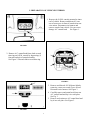
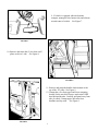
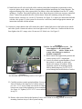
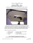
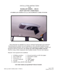
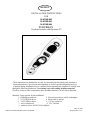
KEMCO
INSTALLATION INSTRUCTIONS
FOR
50-0230B-002
50-0230B-003
50-0230B-004
SUBURBAN
Overhead console with flip down TV
These instructions are intended for use only by experienced professionals in the automotive
customizing business. Special tools and equipment, as well as specialized handling and care
of product during installation, may be required. Before beginning this installation, carefully read
through the following instructions. Use extreme care when cutting headliner material.
Check for wiring or other componentry above headliner material. Cut only where indicated.
Materials/ Tools required for this installation:
1. #2 Phillips screwdriver
2. Powered screwdriver or drill with adapter
3. T-15 TORX bit driver
4. Razor knife or similar
5. T-45 TORX bit driver
6. 1/4” hex socket bit
7. Awl or similar tool
8. 3/32” Drill bit
9. Audiovox Series 645/655 Video Module
INSTALLATION INSTRUCTION # 44-0022B
May 26, 1999
Printed in the U.S.A.
MATERIALS PROVIDED FOR INSTALLATION:
ITEM
Description
QTY
1
SCREW, # 8 X 3/4" HWH
4
2
SCREW, # 6 X 1/2" PPH
4
3
SCREW, # 6 X 3/8" PPH
4
4
SCREW, # 8 X 2 1/2" PFH
3
5
SCREW, #8 X 1 1/4" PWH
2
6
MOUNTING BRACKET
1
7
CONSOLE
1
8
LIGHT
2
9
LIGHT TRIM
2
10
PLYWOOD, 3/8" X 6" X 14"
1
11
SCREW, 6-32 X 3/4" PPH
6
12
WASHER, 3.5 mm
4
May 26, 1999
Printed in the U.S.A
INSTALLATION INSTRUCTION # 44-0022B
2
I. PREPARATION OF VEHICLE INTERIOR
1. Remove the O.E.M. console mounted to inner
roof of vehicle. Remove and discard (1) one
screw from recess in front of console near rear
view mirror. Disconnect wire harness and
remove console from vehicle. Use care not to
damage A/C control head.
See Figure 1.
FIGURE 1
2. Remove A/C control head from cloth covered
trim ring on O.E M. console by depressing (4)
four tabs on back of control assembly.
See Figure 2. Discard cloth covered trim ring.
FIGURE 2
3. Remove and discard O.E.M. dome light by
removing center cover and (2) two screws.
Disconnect wire harness. See Figure 3.
4. Carefully remove and retain bezel from rear
A/C control head and lay it in a safe place.
See Fig. 3.
5. Remove and retain rear A/C control head and
lay it in a safe place. See Figure 3.
FIGURE 3
3
6. Carefully trim headliner from the dome light area
toward the front of vehicle as shown. See figure 4.
Caution: Before cutting headliner material, check
for wiring or other componentry above headliner.
Cut only where indicated.
FIGURE 4
7. Install the mounting bracket in the O.E.M. dome light
area. Align the front mounting tabs with the openings in
the metal inner roof. Slide bracket rearward until flange
contacts rear edge of recessed area. See Fig. 5.
FIGURE 5
8. Secure bracket to sheet metal frame using (4) four
# 8 x 3/4" TEK screws. See Figure 6.
FIGURE 6
4
9. If vehicle is equipped with an electronic
compass, unsnap the wire harness clip and relocate
toward center of vehicle. See Figure 7.
FIGURE 7
10. Remove and retain the (2) two door scuff
plates on driver’s side. See Figure 8.
FIGURE 8
11. Remove and retain the handle which mounts to the
top of the “B” pillar. See Figure 9.
12. Unsnap the cover from upper and lower mounting
bracket for the seat belt. Remove and retain TORX
head bolt and bracket. Carefully pull panel away from
side of vehicle. Unsnap upper door trim from
headliner and lay aside. See Figure 9.
FIGURE 9
5
13. Measure 7” from rear A/C control opening
toward the rear of vehicle. Using a razor knife,
carefully cut an opening in the headliner that is
6” wide x 8 3/4” long. Make sure that the 6”
width is centered in the vehicle. Caution: Before
cutting headliner material, check for wiring
or other componentry above headliner. Cut
only where indicated.
See Figure 10.
14. Insert the 6” x 14” piece of plywood through
opening and rotate 90 degrees. See Figure 10.
FIGURE 10
II. PREPARATION OF CONSOLE FOR INSTALLATION
15. Install front light fixture and secure using (3) three
# 6 x 1/2” screws. Make sure fixture is centered.
See Figure 11.
16. Install trim ring around light.
17. Install rear light fixture and secure using (1) one
# 6 x 1/2” screw in the center hole only. Make sure
fixture is centered. Predrill the remaining (2) two
holes using a 3/32” drill bit.
18. Install front A/C controls original manner. Secure
using four (4) # 6 x 3/8” screws.
See Figure 11.
FIGURE 11
III. INSTALLATION OF CONSOLE
NOTE: Additional assistance in mounting the overhead console in vehicle is advised
to prevent damage to console or components.
6
19. Install and route all video and audio cables, and any other added component requirements to their
respective places in the vehicle. Refer to component installation instructions for wiring diagrams. The
suggested routing of the video system cable is as follows: Above the headliner from rear A/C switch
opening to B-pillar. Down the B-pillar to the floor. Route the power lead to an accessory controlled
source. Connect the ground lead to the vehicle chassis. Route the remaining wiring (RCA plugs,
Remote Sensor extension, etc.) to the VCP location. See Figure 12. Connect per instructions included
with the video system. If video system if to be used as a television, install an appropriate antenna per
instructions included with the antenna.
20. Construct a jumper harness that will connect the vehicle’s dome light wires to the lights in the console
and video system. Connect the white wires from lights to the O.E. white wire. Connect the black wires
from lights to the O.E. orange wires. Do not use O.E. black wire. See Figure 13.
12 screws. Use
Caution: Do notFIGURE
overtighten
extra support for the console until
secured to the
vehicle. Failure to do
so may cause damage to console or
installed components.
21. Raise console into approximate position and
connect wiring to O.E. components.
22. Loosely fit console against headliner. Check
that console is centered in vehicle and
matches all contours of headliner. While
supporting console in mounting position,
loosely install using two (2) 6-32 X 3/4"
screws through the smaller holes in bracket
on console
FIGURE 13
into threaded clips on mounting bracket. See Figure 14.
23. Carefully position console against headliner. Secure the
front of console to the inner roof of vehicle using (2)
two # 8 x 1 1/4" screws. Make sure console is centered
between sun visors before tightening screws completely.
See Figure 16. Tighten (2) 6-32 X 3/4" screws installed
in step 22.
FIGURE
14 for access to
24. Release video screen from locked position. Lower video screen to viewing
position
mounting locations in top of video system housing.
7
25. Raise video system into approximate position and connect all wiring to components. Route video
cable through hole in mounting bracket. Connect wiring and cabling to video system per
instructions included with video system. Make sure lights in video system operate with door jamb
switch.
26. Check function of all components and lights. See operating instructions for video system
operations check. For further assistance, refer to the video system manual for the technical support
phone number listed for your area.
27. Attach O.E. wiring to rear A/C control head. Carefully
snap O.E. trim ring around control head. Insert control
head into opening and press firmly to engage tabs.
28. Secure rear of console to headliner using (2) two #8 x
2 1/2" screws at the rear light.
NOTE: Make
sure the plywood is centered in the rear light area
before installing screws. To prevent warpage of
console or damage to roof of vehicle, do not
overtighten screws. See Figure 16. Remove and
discard the # 6 x 1/2" screw from the center mounting
location and replace with (1) one # 8 x 2 1/2" screw.
29. Install trim over rear light fixture.
FIGURE 15
30. Snap “B” pillar panel in place and
secure seat belt bracket using original
fasteners.
IMPORTANT - TORQUE SEAT BELT
BRACKET TO MFG.
SPECIFICATION.
31. Reinstall handle and door trim to top of
“B” pillar in original position.
32. Install door scuff plates in original position.
FIGURE 16
8