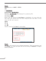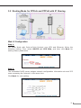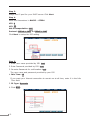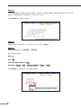
1
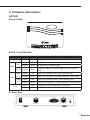
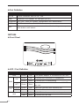
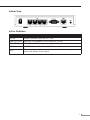
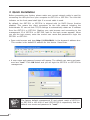
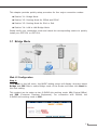
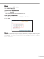
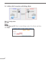
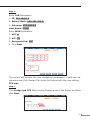
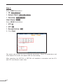
G.SHDSL.bis Bridge Router
GRT-501 / GRT-504
Quick Installation Guide
Table of Contents
Overview
................................................................................................. 3
1. Package Content.......................................................................................... 4
2. Hardware Description................................................................................... 5
3. Quick Installation......................................................................................... 8
3.1 Bridge Mode........................................................................................ 9
3.2 Routing Mode for PPPoA and PPPoE with IP Sharing...............................11
3.3 Routing Mode for IPoA or EoA..............................................................13
3.4 LAN-to-LAN Connection with Bridge Mode..............................................16
4. Further configuration...................................................................................19
Overview
Thank you for purchases the Planet GRT-501 or GRT-504. The GRT-501 and GRT504 are the G.SHDSL.bis routers that comply with ITU-T G.991.2 standard and
provide affordable, flexible, efficient Internet access solution for SOHO and Small
Medium Business environment. The GRT-501 and GRT-504 support business-class,
multi-range from 192 Kbps to 5.7 Mbps (2-wire) and 384 Kbps to 11.4 Mbps (4wire) symmetric data rates by using existing telephone copper wires.
This quick installation guide includes the following sections:
1.Package Content
2.Hardware Description: Hardware outlook and panel description
3.Quick Installation: Quick setup through Web browser
4.Further Configuration
1. Package Content
GRT-501 / GRT-504
ó G.SHDSL.bis Bridge Router x 1
ó Power Adapter x 1
ó Quick Installation Guide x 1
ó User’s manual CD x 1
ó Console Cable x 1
ó RJ-45 to RJ-11 Cable x 1
If any of the above items are missing or damaged, please contact your local dealer
for support.
2. Hardware Description
GRT-501
►Front Panel
►LED / Port Definition
LEDs
PWR
Green
ON
Description
The power adaptor is connected to GRT-501
Green
ON
Green
Blink
SHDSL.bis is handshaking
ACT
Green
Blink
Transmit data or receive data over SHDSL.bis
link
10M/
ACT
Green
ON
Green
Blink
LNK
WAN
LAN
Color Active
100M/ Green
ACT
Green
ALM
ON
Blink
Red
ON
Red
Blink
SHDSL.bis connection is established
LAN Port connect with 10M Ethernet link
LAN Port Transmit or receive data in 10M mode
LAN Port connect with 100M Ethernet link
LAN Port Transmit or receive data in 100M mode
SHDSL.bis line connection is dropped
SHDSL.bis self test
► Rear View
►Port Definition
Port
Description
DC-IN
Power connector with 9V DC 1.0A
LAN
Ethernet 10/100BaseT for LAN port (RJ-45)
CONSOLE
RS-232C (DB9) for system configuration and maintenance
LINE
SHDSL.bis interface for WAN Port
RST
The reset button, the router restore the default settings when press
this button until reboot.
GRT-504
►Front Panel
►LED / Port Definition
LEDs
PWR
ON
The power adaptor is connected to GRT-504
Green
ON
G.SHDSL.bis connection is established
Green
Blink
G.SHDSL.bis is handshaking
ACT
Green
Blink
Transmit data or receive data over G.SHDSL.
bis link
1/2/3/4
Green
ON
1/2/3/4
Green
Blink
WAN
ALM
Description
Green
LNK
LAN
Color Active
Red
ON
Red
Blink
LAN Port connect with Ethernet link
LAN Port Transmit or receive data
G.SHDSL.bis line connection is dropped
G.SHDSL.bis self test
►Rear View
►Port Definition
Port
Description
DC-IN
Power connector with 9V DC 1.0A
LAN (1/2/3/4)
Ethernet 10/100Base-TX for LAN port (RJ-45)
CONSOLE
RS- 232C (DB9) for system configuration and maintenance
LINE
G.SHDSL.bis interface for WAN Port
RST
The reset button, the router restore the default settings when
press this button until reboot.
3. Quick Installation
Before proceeding any further, please make sure correct network cable is used for
connecting the LAN port from your computer to GRT-501 or GRT-504. The LAN LNK
indicator on the front panel shall light if a correct cable is used.
By default, the GRT-501 or GRT-504 is shipped with its DHCP Server function
enabled. This means the client computers on the LAN network including the
Administrator PC can set their TCP/IP settings to automatically obtain an IP address
from the GRT-501 or GRT-504. Starting your web browser and connecting to the
management IP of GRT-501 or GRT-504, wait for the login screen appears. When
you see the login screen, enter the correct user name and password to login the
GRT-501 or GRT-504.
ó Open web browser and type http://192.168.0.1 in the browser’s address box.
This number is the default IP address for this device. Press Enter.
ó A user name and password prompt will appear. The default user name and password are “root”. Click OK button and you will login the GRT-501 or GRT-504 for
management.
Note
The factory default management IP and subnet mask of GRT-501
or GRT-504 is 192.168.0.1 and 255.255.255.0 respectively. And the
default user name and password is “root”.
This chapter provides quickly setup procedure for four major connection modes:
nSection 3.1: Bridge Mode
nSection 3.2: Routing Mode for PPPoA and PPPoE
nSection 3.3: Routing Mode for IPoA or EoA
nSection 3.4: LAN to LAN Bridge Mode
Please verify your connection mode and check the corresponding section to quickly
install your GRT-501 or GRT-504.
3.1 Bridge Mode
Web UI Configuration
Step 1.
Click Basic on the left menu, the BASIC setting screen will display. And then select
Bridge and CPE Side to setup Bridge mode of the Router and then click Next for
the next setting.
This product can be setup as two G.SHDSL.bis working mode: CO (Central Office)
and CPE (Customer Premises Equipment). For connection with DSLAM, the
G.SHDSL.bis working mode is CPE.
Step 2.
Enter Parameters in BASIC – STEP2:
LAN
IP: 192.168.0.1
Subnet Mask: 255.255.255.0
Gateway: 192.168.0.254 (The Gateway IP is provided by ISP)
Host Name: SOHO
Some of the ISP requires the Host Name as identification. You may check with
ISP to see if your Internet service has been configured with a host name. In most
cases, this field can be ignored.
WAN1
VPI: 0
VCI: 32
Click LLC, and then Click Next for next setting.
Step 3.
The screen will prompt the new configured parameters. Check the parameters and
click Restart. The router will reboot with the new setting or Continue to configure
another parameters.
10
3.2 Routing Mode for PPPoA and PPPoE with IP Sharing
Web UI Configuration
Step 1.
For Route Mode with Point-to-Point Protocol over ATM and Ethernet, follow the
following setting. First, select ROUTE and CPE Side, and then click Next for
setting others parameters.
Step 2.
The embedded DHCP server assigns network configuration information at most 253
users accessing the Internet in the same time.
Click Next for next setting.
11
Step 3.
Assign the IP pool for your DHCP server. Click Next.
Step 4.
Enter the Parameters in BASIC – STEP4
VPI: 0
VCI: 32
AAL5 Encapsulation: LLC
Protocol: PPPoA + NAT or PPPoE + NAT
Click Next to setup the ISP setting.
Step 5.
1.Enter user name provided by ISP: test
2.Enter Password provided by ISP: test
3.Re-enter Password for confirmation: test
The user name and password provided by your ISP.
4.Idle Time: 10
If you want your Internet connection to remain on at all time, enter 0 in the Idle
Time field.
5.IP Type: Dynamic
6.Click Next.
12
Step 6.
The screen will prompt the new configured parameters. Check the parameters and
click Restart. The router will reboot with the new setting or Continue to configure
another parameters.
3.3 Routing Mode for IPoA or EoA
Web UI Configuration
Step 1.
For Route Mode with IPoA and EoA, follow the following setting. First, select
ROUTE and CPE Side, and then click Next for setting others parameters.
13
Step 2.
The embedded DHCP server assigns network configuration information at most 253
users accessing the Internet in the same time.
Click Next for next setting.
Step 3.
Assign the IP pool for your DHCP server. Click Next.
Step 4.
Enter Parameters in BASIC – STEP4
Wan Parameters;
VPI: 0
VCI: 32
AAL5 Encapsulation: LLC
Protocol: IPoA , EoA , IPoA + NAT or EoA + NAT
Click Next to setup the IP parameters.
14
Step 5.
Enter Parameters in WAN setting.
1.IP Address: 10.1.2.1
2.Subnet mask: 255.255.255.0
3.Gateway: 10.1.2.2
Your ISP will provide above information to you.
4.DNS Server 1: 168.95.1.1
Your ISP will provide at least one DNS Server IP address.
5.Click Next.
Step 6.
The screen will prompt the new configured parameters. Check the parameters and
click Restart. The router will reboot with the new setting or Continue to configure
another parameters.
15
3.4 LAN-to-LAN Connection with Bridge Mode
Web UI Configuration
CO side
Step 1.
Click Bridge and CO Side to setup Bridge mode of the Router and then
click Next.
16
Step 2.
Enter LAN Parameters
1. IP: 192.168.0.1
2. Subnet Mask: 255.255.255.0
3. Gateway: 192.168.0.2
Host Name: SOHO
Enter WAN Parameters
1. VPI: 0
2. VCI: 32
3. Encapsulation: LLC
4. Click Next
The screen will prompt the new configured parameters. Check the parameters and Click Restart The router will reboot with the new setting.
CPE side
Step 1.
Click Bridge and CPE Side to setup Bridge mode of the Router and then
click Next.
17
Step 2.
Enter LAN Parameters
1. IP: 192.168.0.2
2. Subnet Mask: 255.255.255.0
3. Gateway: 192.168.0.1
Host Name: SOHO
Enter WAN Parameters
1. VPI: 0
2. VCI: 32
3. Encapsulation: LLC
4. Click Next
The screen will prompt the new configured parameters. Check the parameters and
Click Restart The router will reboot with the new setting.
After rebooting, the GRT-501 or GRT-504 will establish a connection and the PC1
and PC2 can access to each other.
18
4. Further configuration
The above steps introduce simple configurations for GRT-501 or GRT-504. For
further configurations such as DMZ, Virtual Server, or VLAN functions, please refer
to the user’s manual in the CD. If you have other questions, please contact the
local dealer or distributor where you purchased this product.
19
This page is intentionally left blank