1
ADSL 2/2+ VoIP Router
IAD-200, IAD-200W
User's Manual
Copyright
Copyright (C) 2005 PLANET Technology Corp. All rights reserved.
The products and programs described in this User’s Manual are licensed
products of PLANET Technology, This User’s Manual contains proprietary
information protected by copyright, and this User’s Manual and all
accompanying hardware, software, and documentation are copyrighted.
No part of this User’s Manual may be copied, photocopied, reproduced,
translated, or reduced to any electronic medium or machine-readable form by
any means by electronic or mechanical. Including photocopying, recording, or
information storage and retrieval systems, for any purpose other than the
purchaser's personal use, and without the prior express written permission of
PLANET Technology.
Disclaimer
PLANET Technology does not warrant that the hardware will work properly in
all environments and applications, and makes no warranty and representation,
either implied or expressed, with respect to the quality, performance, merchantability, or fitness for a particular purpose.
PLANET has made every effort to ensure that this User’s Manual is accurate;
PLANET disclaims liability for any inaccuracies or omissions that may have
occurred.
Information in this User’s Manual is subject to change without notice and does
not represent a commitment on the part of PLANET. PLANET assumes no
responsibility for any inaccuracies that may be contained in this User’s Manual.
PLANET makes no commitment to update or keep current the information in
this User’s Manual, and reserves the right to make improvements to this User’s
Manual and/or to the products described in this User’s Manual, at any time
without notice.
If you find information in this manual that is incorrect, misleading, or incomplete, we would appreciate your comments and suggestions.
FCC Compliance Statement
The device confirmed to comply with the requirements of FCC Part 15 Rule.
ii
Operation is subject to the Following two conditions: (1) This device may not
cause harmful interference, and (2) This Device must accept any interference
received, including interference that may cause undesired operation.
Federal Communication Commission (FCC) Radiation
Exposure Statement
This equipment complies with FCC radiation exposure set forth for an uncontrolled environment. In order to avoid the possibility of exceeding the FCC
radio frequency exposure limits, human proximity to the antenna shall not be
less than 20 cm (8 inches) during normal operation.
CE mark Warning
This is a class B device. In a domestic environment, this product may cause
radio interference, in which case the user may be required to take adequate
measures.
WEEE Warning
To avoid the potential effects on the environment and human health as a result
of the presence of hazardous substances in electrical and electronic equipment,
end users of electrical and electronic equipment should understand the meaning
of the crossed-out wheeled bin symbol. Do not dispose of WEEE as unsorted
municipal waste and have to collect such WEEE separately.
R&TTE Compliance Statement
This equipment complies with all the requirements of DIRECTIVE 1999/5/EC
OF THE EUROPEAN PARLIAMENT AND THE COUNCIL OF 9 March
1999 on radio equipment and telecommunication terminal Equipment and the
mutual recognition of their conformity (R&TTE).
The R&TTE Directive repeals and replaces in the directive 98/13/EEC (Telecommunications Terminal Equipment and Satellite Earth Station Equipment)
as of April 8, 2000.
iii
Trademarks
The PLANET logo is a trademark of PLANET Technology. This documentation may refer to numerous hardware and software products by their trade
names. In most, if not all cases, these designations are claimed as trademarks
or registered trademarks by their respective companies.
Safety
This equipment is designed with the utmost care for the safety of those who
install and use it. However, special attention must be paid to the dangers of
electric shock and static electricity when working with electrical equipment.
All guidelines of this and of the computer manufacture must therefore be allowed at all times to ensure the safe use of the equipment.
To avoid struck by lightning, we suggest customers to add a device (lightning
protector / surge protector) front of this ADSL 2/2+ VoIP router. Improper
installation like without this protection and cause the equipment damaged
could void the warranty.
Revision
User’s Manual for PLANET ADSL 2/2+ VoIP Router
Model: IAD-200, IAD-200W
Rev: 1.0 (Aug. 2005)
Part No. EM-IAD200Wv1
iv
Table of Contents
CHAPTER 1 INTRODUCTION..................................................................... 1
IAD-200 / IAD-200W Features ................................................................. 1
Package Contents ....................................................................................... 4
Physical Details........................................................................................... 5
CHAPTER 2 INSTALLATION ...................................................................... 8
Requirements.............................................................................................. 8
Procedure .................................................................................................... 8
CHAPTER 3 SETUP ...................................................................................... 10
Overview ................................................................................................... 10
Configuration Program ........................................................................... 11
Setup Wizard ............................................................................................ 12
Home Screen............................................................................................. 14
LAN Screen............................................................................................... 15
Wireless Screen (IAD-200W only).......................................................... 17
Wireless Security (IAD-200W only) ....................................................... 20
Trusted Wireless Stations (IAD-200W only) ......................................... 22
Password Screen....................................................................................... 24
CHAPTER 4 PC CONFIGURATION.......................................................... 25
Overview ................................................................................................... 25
Windows Clients....................................................................................... 25
Macintosh Clients..................................................................................... 36
Linux Clients ............................................................................................ 36
Other Unix Systems ................................................................................. 36
Wireless Station Configuration (IAD-200W only)................................ 37
Wireless Configuration on Windows XP (IAD-200W only)................. 37
CHAPTER 5 ADVANCED FEATURES...................................................... 47
Overview ................................................................................................... 47
Internet...................................................................................................... 47
Dynamic DNS (Domain Name Server)................................................... 52
Firewall Rules ........................................................................................... 54
User-defined Services............................................................................... 59
Options ...................................................................................................... 61
Schedule .................................................................................................... 62
Virtual Servers ......................................................................................... 64
VoIP........................................................................................................... 67
CHAPTER 6 ADVANCED ADMINISTRATION....................................... 72
Overview ................................................................................................... 72
PC Database.............................................................................................. 73
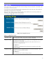
Config File................................................................................................. 77
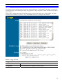
Logs ........................................................................................................... 78
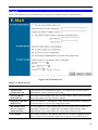
E-mail ........................................................................................................ 80
Diagnostics ................................................................................................ 82
Remote Administration ........................................................................... 83
i
Routing ...................................................................................................... 85
Upgrade Firmware................................................................................... 89
CHAPTER 7 OPERATION AND STATUS ................................................ 90
Operation .................................................................................................. 90
Status Screen ............................................................................................ 90
Connection Status - PPPoE & PPPoA.................................................... 94
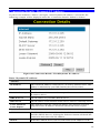
Connection Details - Dynamic IP Address............................................. 95
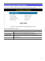
Connection Details - Fixed IP Address .................................................. 97
Using VoIP ................................................................................................ 98
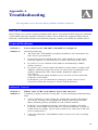
APPENDIX A TROUBLESHOOTING........................................................ 99
Overview ................................................................................................... 99
General Problems..................................................................................... 99
Internet Access ......................................................................................... 99
Wireless Access (IAD-200W only) ........................................................ 100
APPENDIX B ABOUT WIRELESS LANS (IAD-200W ONLY) ............ 102
Modes ...................................................................................................... 102
BSS/ESS .................................................................................................. 102
Channels.................................................................................................. 103
WEP......................................................................................................... 103
WPA-PSK ............................................................................................... 103
Wireless LAN Configuration ................................................................ 104
ii
Chapter 1
Introduction
1
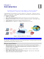
This Chapter provides an overview of the ADSL 2/2+ VoIP router (IAD-200)
/ 802.11g ADSL 2/2+ VoIP router's (IAD-200W) features and capabilities.
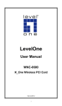
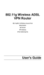
Congratulations on the purchase of your new ADSL 2/2+ VoIP router – IAD-200 / 802.11g
ADSL 2/2+ VoIP router – IAD-200W. The IAD-200 / IAD-200W is a multi-function device
providing the following services:
•
•
•
•
•
ADSL 2/2+ Modem.
Shared Broadband Internet Access (NAT Router) for all LAN & WLAN users.
Wireless Access Point for 802.11b and 802.11g Wireless Stations. (IAD-200W only)
VoIP Gateway supporting the industry-standard SIP protocol.
Ethernet Port for 10BaseT or 100BaseT connection to your LAN.
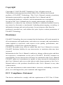
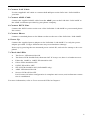
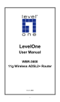
Figure 1: 802.11g ADSL 2/2+ VoIP router
IAD-200 / IAD-200W Features
The IAD-200 / IAD-200W incorporates many advanced features, carefully designed to provide
sophisticated functions while being easy to use.
Internet Access Features
•
Shared Internet Access. All users on the LAN or WLAN can access the Internet
through the IAD-200 / IAD-200W, using only a single external IP Address. The local (invalid) IP Addresses are hidden from external sources. This process is called NAT
(Network Address Translation).
•
Built-in ADSL Modem. The IAD-200 / IAD-200W has a built-in ADSL modem,
supporting all common ADSL connections.
•
IPoA, PPPoE, PPPoA, Direct Connection Support. The IAD-200 / IAD-200W
supports all common connection methods.
1
•
Auto-detection of Internet Connection Method. In must situations, the IAD-200 /
IAD-200W can test your ADSL and Internet connection to determine the connection
method used by your ISP.
•
Fixed or Dynamic IP Address. On the Internet (WAN port) connection, the IAD-200 /
IAD-200W supports both Dynamic IP Address (IP Address is allocated on connection)
and Fixed IP Address.
Advanced Internet Functions
•
Application Level Gateways (ALGs). Applications which use non-standard connections or port numbers are normally blocked by the Firewall. The ability to define and
allow such applications is provided, to enable such applications to be used normally.
•
Special Applications. This feature, also called Port Triggering, allows you to use
Internet applications which normally do not function when used behind a firewall.
•
Virtual Servers. This feature allows Internet users to access Internet servers on your
LAN. The required setup is quick and easy.
•
Dynamic DNS Support. DDNS, when used with the Virtual Servers feature, allows
users to connect to Servers on your LAN using a Domain Name, even if you have a dynamic IP address which changes every time you connect.
•
•
URL Filter. Use the URL Filter to block access to undesirable Web sites by LAN users.
Firewall. As well as the built-in firewall to protect your LAN, you can define Firewall
Rules to determine which incoming and outgoing traffic should be permitted.
•
Scheduling. Both the URL Filter and Firewall rules can be scheduled to operate only at
certain times. This provides great flexibility in controlling Internet -bound traffic.
•
Logs. Define what data is recorded in the Logs, and optionally send log data to a Syslog
Server. Log data can also be E-mailed to you.
•
VPN Pass through Support. PCs with VPN (Virtual Private Networking) software
using PPTP, L2TP, and IPSec are transparently supported - no configuration is required.
VoIP Features
•
SIP Standard Compatible. The IAD-200 / IAD-200W complies with the SIP standard
for VoIP.
•
Advanced Call features. Caller ID, Caller name, Call waiting, three-way conference
call, DTMF relay, Voice active detection, Echo canceller.
•
FAX Support. Both the T.38 and G.711 Fax standards are supported, allowing both
sending and receiving faxes via the Wireless VoIP Gateway.
•
Life line (PSTN fallback) Support. The PSTN (analogue phone) port is automatically
used when the Internet connection is not operational or there is a power failure.
Wireless Features (IAD-200W only)
•
Standards Compliant. The IAD-200W complies with the IEEE802.11g (DSSS) specifications for Wireless LANs.
•
Supports both 802.11b and 802.11g Wireless Stations. The 802.11g standard
provides for backward compatibility with the 802.11b standard, so both 802.11b and
802.11g Wireless stations can be used simultaneously.
•
Speeds up and exceeding 54Mbps. All speeds up to the 802.11g maximum of 54Mbps
are supported. Also, the IAD-200W support TI's proprietary "g-Plus" solution, which allows even faster speeds between compatible wireless devices.
2
•
WEP support. Support for WEP (Wired Equivalent Privacy) is included. Key sizes of
64 Bit and 128 Bit are supported. WEP encrypts any data before transmission, providing
protection against snoopers.
•
WPA-PSK support. Like WEP, WPA-PSK encrypts any data before transmission,
providing protection against snoopers. The WPA-PSK is a later standard than WEP, and
provides both easier configuration and greater security than WEP.
•
Wireless MAC Access Control. The Wireless Access Control feature can check the
MAC address (hardware address) of Wireless stations to ensure that only trusted Wireless
Stations can access your LAN.
•
Simple Configuration. If the default settings are unsuitable, they can be changed
quickly and easily.
LAN Features
•
Ethernet Port. The IAD-200 / IAD-200W incorporates a 10/100BaseT port for connection to your existing LAN.
•
DHCP Server Support. Dynamic Host Configuration Protocol provides a dynamic IP
address to PCs and other devices upon request. The IAD-200 / IAD-200W can act as a
DHCP Server for devices on your local LAN and WLAN.
Configuration & Management
•
Easy Setup. Use your WEB browser from anywhere on the LAN or WLAN for configuration.
•
Configuration File Upload/Download. Save (download) the configuration data from
the IAD-200 / IAD-200W to your PC, and restore (upload) a previously-saved configuration file to the device.
•
Remote Management. The IAD-200 / IAD-200W can be managed from any PC on
your LAN or Wireless LAN. And, if the Internet connection exists, it can also (optionally)
be configured via the Internet.
•
Network Diagnostics. You can use the IAD-200 / IAD-200W to perform a Ping or
DNS lookup.
Security Features
•
Password - protected Configuration. Password protection is provided to prevent
unauthorized users from modifying the configuration data and settings.
•
Wireless LAN Security. WPA-PSK, WEP, and Wireless access control by MAC
address are all supported. The MAC-level access control feature can be used to prevent
unknown wireless stations from accessing your LAN.
•
NAT Protection. An intrinsic side effect of NAT (Network Address Translation) technology is that by allowing all LAN users to share a single IP address, the location and
even the existence of each PC is hidden. From the external viewpoint, there is no network,
only a single device - the IAD-200 / IAD-200W.
•
Firewall. All incoming data packets are monitored and all incoming server requests are
•
Protection against DoS attacks. DoS (Denial of Service) attacks can flood your
filtered, thus protecting your network from malicious attacks from external sources.
Internet connection with invalid packets and connection requests, using so much bandwidth and so many resources that Internet access becomes unavailable. The IAD-200 /
IAD-200W incorporates protection against DoS attacks.
3
Package Contents
The following items should be included. If any of these items are damaged or missing, please
contact your dealer immediately.
•
The IAD-200 / IAD-200W Unit
•
1 Cat-5 Ethernet (LAN) cable
•
1 RJ-11 (ADSL) cable
•
Power Adapter
•
Quick Installation Guide
•
CD-ROM containing the on-line manual.
4
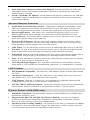
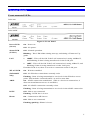
Physical Details
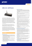
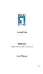
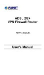
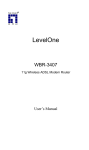
Front-mounted LEDs
IAD-200
IAD-200W
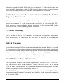
Figure 2: Front Panel
Power LED
(Green)
On - Power on.
Status LED
(Yellow)
Off - Normal operation.
LAN
•
100BT - This will be ON if the LAN connection is using 100BaseT,
and Blinking if data is being transferred via the LAN port.
•
10BT - This will be ON if the LAN connection is using 10BaseT, and
Blinking if data is being transferred via the LAN port.
Off - No power.
Blinking - This LED blinks during start up, and during a Firmware Upgrade.
If neither LED is on, there is no active connection on the LAN port.
WLAN LED
On - Wireless enabled.
(IAD-200W
only)
Off - No Wireless connections currently exist.
ADSL
On - ADSL connection established. (This is a low-level connection, it
does not mean Internet access is available.)
Flashing - Data is being transmitted or received via the Wireless access
point. This includes "network traffic" as well as user data.
Off - No ADSL connection currently exists.
Flashing - Data is being transmitted or received via the ADSL connection.
PSTN
Off - Idle or not connected.
Flashing - PSTN line is in use.
Phone
On - Connected to SIP Server.
Off - Idle or not connected.
Flashing (quickly) -Phone is in use.
5
Internet
On - Internet connection is available.
Off - No Internet connection available.
Flashing - Data is being transmitted or received.
6
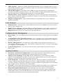
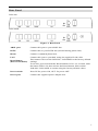
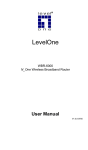
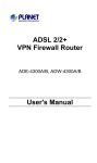
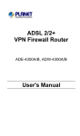
Rear Panel
IAD-200
IAD-200W
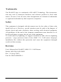
Figure 3: Rear Panel
ADSL port
Connect this port to your ADSL line.
PSTN
Connect this to your PSTN line (normal analog phone line).
Phone
Connect a standard phone here.
LAN
Connect this port to your hub, using the supplied LAN cable.
Reset Button
(Reset to Defaults)
This button will reset the IAD-200 / IAD-200W to the factory default
settings.
To do this, press and hold the Reset Button for five (5) seconds, until
the Status LED is lit, then release the Reset Button, and wait the
IAD-200 / IAD-200W to restart using the factory default values.
Power switch
Press IN for power ON, OUT for power OFF.
Power port
Connect the supplied power adapter here.
7
2
Chapter 2
Installation
This Chapter covers the physical installation of the ADSL 2/2+ VoIP router
(IAD-200) / 802.11g ADSL 2/2+ VoIP router (IAD-200W).
Requirements
•
TCP/IP protocol must be installed on all PCs.
•
To use the Wireless Access Point, all Wireless devices must be compliant with the IEEE
802.11g or IEEE 802.11b specifications.
•
For Internet Access, an ADSL service and ISP account.
•
For VoIP, a SIP account with a VoIP service provider.
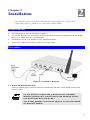
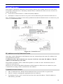
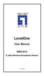
Procedure
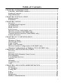
Figure 4: Installation Diagram
1. Choose an Installation Site
Select a suitable place on the network to install the IAD-200 / IAD-200W. Ensure the
power is OFF.
For best Wireless reception and performance, the IAD-200W
should be positioned in a central location with minimum obstructions between the device and the PCs.
Also, if using multiple Access Points, adjacent Access Points should
use different Channels.
8
2. Connect LAN Cable
Use the supplied LAN cable to connect the LAN port on the IAD-200 / IAD-200W to
your hub.
3. Connect ADSL Cable
Connect the supplied ADSL cable from the ADSL port on the IAD-200 / IAD-200W to
the ADSL terminator provided by your phone company.
4. Connect PSTN Line
Connect the PSTN socket on the rear of the IAD-200 / IAD-200W to your normal phone
line socket.
5. Connect Phone
Connect a standard phone to the Phone socket on the rear of the IAD-200 / IAD-200W.
6. Power Up
Connect the supplied power adapter to the IAD-200 / IAD-200W. Use only the power
adapter provided. Using a different one may cause hardware damage.
Power up by pressing the rear-mounted power switch IN, and wait for startup to be completed.
7. Check the LEDs
•
The Power LED should be ON.
•
The Status LED should flash, then turn Off. If it stays on, there is a hardware error.
•
Either the 100BT or 10BT LED should be ON.
•
Phone LED should be OFF.
•
PSTN LED will be OFF.
•
WLAN LED should be ON (IAD-200W only).
•
ADSL LED should be ON.
•
Internet LED will be OFF.
It will come ON when configuration is complete and correct, and an Internet connection is established.
For more information, refer to Front-mounted LEDs in Chapter 1.
9
3
Chapter 3
Setup
This Chapter provides Setup details of the IAD-200 / IAD-200W.
Overview
This chapter describes the setup procedure for:
•
Internet Access
•
LAN configuration
•
Wireless setup
•
Assigning a Password to protect the configuration data.
PCs on your local LAN may also require configuration. For details, see Chapter 4 - PC Configuration.
Other configuration may also be required, depending on which features and functions of the
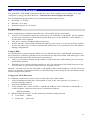
IAD-200 / IAD-200W you wish to use. Use the table below to locate detailed instructions for
the required functions.
To Do this:
Refer to:
Configure PCs on your LAN.
Chapter 4:
PC Configuration
Use any of the following Advanced features:
Chapter 5:
Advanced Features
•
Internet (DMZ, Special Applications, URL Filter)
•
Dynamic DNS
•
Firewall Rules
•
Firewall Services
•
Options
•
Schedule
•
Virtual Servers
•
VoIP
Use any of the following Administration features:
•
PC Database
•
Config File
•
Logs
•
E-mail
•
Diagnostics
•
Remote Admin
•
Routing
•
Upgrade Firmware
Check IAD-200 / IAD-200W operation and Status.
Chapter 6
Advanced Administration
Chapter 7:
Operation and Status
10
Configuration Program
The IAD-200 / IAD-200W contains an HTTP server. This enables you to connect to it, and
configure it, using your Web Browser. Your Browser must support JavaScript.
The configuration program has been tested on the following browsers:
•
Netscape 7.1 or later.
•
Mozilla 1.6 or later
•
Internet Explorer V5.5 or later
Preparation
Before attempting to configure the IAD-200 / IAD-200W, please ensure that:
•
Your PC can establish a physical connection to the IAD-200 / IAD-200W. The PC and the
device must be directly connected (using the Hub ports on the IAD-200 / IAD-200W) or
on the same LAN segment.
•
The device must be installed and powered ON.
•
If the IAD-200 / IAD-200W's default IP Address (192.168.0.1) is already used by another
device, the other device must be turned OFF until the device is allocated a new IP Address
during configuration.
Using UPnP
If your Windows system supports UPnP, an icon for the IAD-200 / IAD-200W will appear in
the system tray, notifying you that a new network device has been found, and offering to create
a new desktop shortcut to the newly-discovered device.
•
Unless you intend to change the IP Address of the IAD-200 / IAD-200W, you can accept
the desktop shortcut.
•
Whether you accept the desktop shortcut or not, you can always find UPnP devices in My
Network Places (previously called Network Neighborhood).
Double - click the icon for the IAD-200 / IAD-200W (either on the Desktop, or in My Network
Places) to start the configuration. Refer to the following section Setup Wizard for details of the
initial configuration process.
Using your Web Browser
To establish a connection from your PC to the IAD-200 / IAD-200W:
1. After installing the IAD-200 / IAD-200W in your LAN, start your PC. If your PC is
already running, restart it.
2. Start your WEB browser.
3. In the Address box, enter "HTTP://" and the IP Address of the IAD-200 / IAD-200W, as
in this example, which uses the device's default IP Address:
HTTP://192.168.0.1
4. When prompted to login, use the following username and password.
•
User name:
admin
•
Password:
password
11
If you cannot connect
If the IAD-200 / IAD-200W does not respond, check the following:
•
The IAD-200 / IAD-200W is properly installed, LAN connection is OK, and it
is powered ON. You can test the connection by using the "Ping" command:
•
Open the MS-DOS window or command prompt window.
•
Enter the command:
ping 192.168.0.1
If no response is received, either the connection is not working, or your
PC's IP address is not compatible with the IAD-200 / IAD-200W's IP Address. (See next item.)
•
If your PC is using a fixed IP Address, its IP Address must be within the range
192.168.0.2 to 192.168.0.254 to be compatible with the IAD-200 / IAD200W's default IP Address of 192.168.0.1. Also, the Network Mask must be set
to 255.255.255.0. See Chapter 4 - PC Configuration for details on checking
your PC's TCP/IP settings.
•
Ensure that your PC and the IAD-200 / IAD-200W are on the same network
segment. (If you don't have a router, this must be the case.)
•
Ensure you are using the wired LAN interface. The Wireless interface can only
be used if its configuration matches your PC's wireless settings.
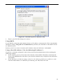
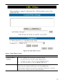
Setup Wizard
The first time you connect to the IAD-200 / IAD-200W, you should run the Setup Wizard to
configure the IAD-200 / IAD-200W for Internet access.
1. Select Setup Wizard on the main menu.
2. Step through the Wizard until finished.
•
3.
4.
You need the data supplied by your ISP. Most connection methods require some data
input.
• The common connection types are explained in the following table.
On the final screen of the Wizard, run the test and check that an Internet connection can be
established.
If the connection test fails:
•
Check all connections, and the front panel LEDs.
•
Check that you have entered all data correctly.
12
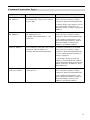
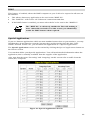
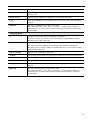
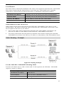
Common Connection Types
Type
Details
ISP Data required
Dynamic
IP Address
Your IP Address is allocated
automatically, when you connect
to you ISP.
a) ADSL parameters (VPI and
VCI) may be required, if they
cannot be detected automatically.
b) Some ISP's may require you to
use a particular Hostname or
Domain name, or MAC (physical)
address.
Static (Fixed)
IP Address
PPPoE, PPPoA
Your ISP allocates a permanent
IP Address to you.
Usually, the connection is "Always on".
a) ADSL parameters (VPI and
VCI) may be required, if they
cannot be detected automatically.
You connect to the ISP only when
required. The IP address is
usually allocated automatically.
a) ADSL parameters (VPI and
VCI) may be required, if they
cannot be detected automatically.
b) IP Address allocated to you,
and related information, such as
Network Mask, Gateway IP
address, and DNS address.
b) User name and password are
always required.
c) If using a Static (Fixed) IP
address, you need the IP address
and related information (Network
Mask, Gateway IP address, and
DNS address)
IPoA
(IP over ATM)
Normally, the connection is
"Always on".
a) ADSL parameters (VPI and
VCI) may be required, if they
cannot be detected automatically.
b) IP Address allocated to you,
and related information, such as
Network Mask, Gateway IP
address, and DNS address.
13
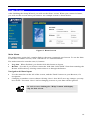
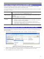
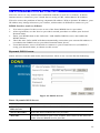
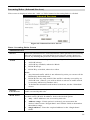
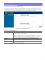
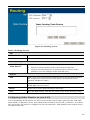
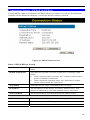
Home Screen
After finishing the Setup Wizard, you will see the Home screen. When you connect in future,
you will see this screen when you connect. An example screen is shown below.
Figure 5: Home Screen
Main Menu
The main menu, on the left, contains links to the most-commonly used screen. To see the links
to the other available screens, click "Advanced" or "Administration".
The main menu also contains two (2) buttons:
•
Log Out - When finished, you should click this button to logout.
•
Restart - Use this if you wish to restart the IAD-200 / IAD-200W. Note that restarting the
Router will break any existing connections to or through the Router.
Navigation & Data Input
•
Use the menu bar on the left of the screen, and the "Back" button on your Browser, for
navigation.
•
Changing to another screen without clicking "Save" does NOT save any changes you may
have made. You must "Save" before changing screens or your data will be ignored.
On each screen, clicking the "Help" button will display
help for that screen.
14
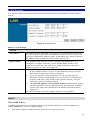
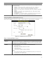
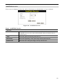
LAN Screen
Use the LAN link on the main menu to reach the LAN screen. An example screen is shown
below.
Figure 6: LAN Screen
Data - LAN Screen
TCP/IP
IP Address
IP address for the IAD-200 / IAD-200W, as seen from the local LAN.
Use the default value unless the address is already in use or your LAN
is using a different IP address range. In the latter case, enter an unused
IP Address from within the range used by your LAN.
Subnet Mask
The default value 255.255.255.0 is standard for small (class "C")
networks. For other networks, use the Subnet Mask for the LAN
segment to which the IAD-200 / IAD-200W is attached (the same
value as the PCs on that LAN segment).
DHCP Server
•
If Enabled, the IAD-200 / IAD-200W will allocate IP Addresses
to PCs (DHCP clients) on your LAN when they start up. The default (and recommended) value is Enabled.
•
If you are already using a DHCP Server, this setting must be
Disabled, and the existing DHCP server must be re-configured to
treat the IAD-200 / IAD-200W as the default Gateway. See the
following section for further details.
•
The Start IP Address and Finish IP Address fields set the values
used by the DHCP server when allocating IP Addresses to DHCP
clients. This range also determines the number of DHCP clients
supported.
See the following section for further details on using DHCP.
DHCP
What DHCP Does
A DHCP (Dynamic Host Configuration Protocol) Server allocates a valid IP address to a
DHCP Client (PC or device) upon request.
•
The client request is made when the client device starts up (boots).
15
•
The DHCP Server provides the Gateway and DNS addresses to the client, as well as
allocating an IP Address.
•
The IAD-200 / IAD-200W can act as a DHCP server.
•
Windows 95/98/ME and other non-Server versions of Windows will act as a DHCP client.
This is the default Windows setting for the TCP/IP network protocol. However, Windows
uses the term Obtain an IP Address automatically instead of "DHCP Client".
•
You must NOT have two (2) or more DHCP Servers on the same LAN segment. (If your
LAN does not have other Routers, this means there must only be one (1) DHCP Server on
your LAN.)
Using the IAD-200 / IAD-200W's DHCP Server
This is the default setting. The DHCP Server settings are on the LAN screen. On this screen,
you can:
•
Enable or Disable the IAD-200 / IAD-200W's DHCP Server function.
•
Set the range of IP Addresses allocated to PCs by the DHCP Server function.
You can assign Fixed IP Addresses to some devices while using
DHCP, provided that the Fixed IP Addresses are NOT within
the range used by the DHCP Server.
Using another DHCP Server
You can only use one (1) DHCP Server per LAN segment. If you wish to use another DHCP
Server, rather than the IAD-200 / IAD-200W's, the following procedure is required.
•
Disable the DHCP Server feature in the IAD-200 / IAD-200W. This setting is on the LAN
screen.
•
Configure the DHCP Server to provide the IAD-200 / IAD-200W's IP Address as the
Default Gateway.
To Configure your PCs to use DHCP
This is the default setting for TCP/IP for all non-Server versions of Windows.
See Chapter 4 - PC Configuration for the procedure to check these settings.
16
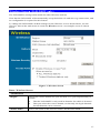
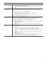
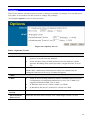
Wireless Screen (IAD-200W only)
The IAD-200W's settings must match the other Wireless stations.
Note that the IAD-200W will automatically accept both 802.11b and 802.11g connections, and
no configuration is required for this feature.
To change the IAD-200W's default settings for the Wireless Access Point feature, use the
Wireless link on the main menu to reach the Wireless screen. An example screen is shown
below.
Figure 7: Wireless Screen
Data - Wireless Screen
Identification
Region
Station name
Select the correct domain for your location. It is your responsibility to
ensure:
•
That the IAD-200W is only used in domains for which is licensed.
•
That you select the correct domain, so that only the legal channels
for that domain can be selected.
This is the same as the "Device Name" for the IAD-200W.
17
SSID
This is also called the "Network Name". Enter the desired value. The
default value is Wireless.
•
If using an ESS (Extended Service Set, with multiple access
points) this ID is called an ESSID (Extended Service Set Identifier).
•
To communicate, all Wireless stations use the same SSID/ESSID,
so must match the value entered here.
Options
Mode
Select the desired mode:
•
Channel No.
Broadcast SSID
802.11G-plus (TI) This allows clients to use any of the following
modes:
•
Standard 802.11b
•
802.11B+ (Texas Instruments proprietary enhanced mode)
•
Standard 802.11g
•
802.11G-plus (Texas Instruments proprietary enhanced
mode). This mode can increase throughput by up to 50%, but
will only work between compatible TI wireless stations.
•
802.11g & 802.11b - Both 802.11.g and 802.11b Wireless stations
will be able to use the IAD-200W.
•
802.11g only - Only 802.11g Wireless stations can use the IAD200W.
•
802.11b only - Only 802.11b connections are available. 802.11g
Wireless Stations will only be able to use the IAD-200W if they
are fully backward-compatible with the 802.11b standard.
Select the Channel you wish to use on your Wireless LAN.
•
If you experience interference (shown by lost connections and/or
slow data transfers) you may need to experiment with different
channels to see which is the best.
•
If using multiple Access Points, adjacent Access Points should use
different Channels to reduce interference.
If enabled, the IAD-200W will broadcast its SSID. This allows PCs
and other wireless stations to detect this Access Point and use the
correct SSID.
If disabled, PC users will have to manually enter the SSID and other
details of the wireless interface before they can connect to this Access
Point.
Wireless Security
Current Setting
The current Wireless security is displayed. The default value is Disabled.
Configure
Button
Click this button to access the Wireless security sub-screen, and view
or change the settings. See the following section for details.
Access Point
Enable Wireless
Enable this if you want to use Wireless Access Point function.
Access Point
If disabled, no Wireless stations can use the Access Point function, and
all connections must be made via the wired LAN.
18
Allow access
by …
Use this feature to determine which Wireless stations can use the
Access Point. The options are:
• All Wireless Stations - All wireless stations can use the access
point, provided they have the correct SSID and security settings.
•
Set Stations
Button
Trusted Wireless stations only - Only wireless stations you
designate as "Trusted" can use the Access Point, even if they have
the correct SSID and security settings.
This feature uses the MAC address to identify Wireless stations.
The MAC address is a low-level network identifier which is
unique to each PC or network device.
To define the trusted wireless stations, use the "Set Stations" button.
Click this button to manage the trusted PC database.
19
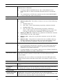
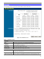
Wireless Security (IAD-200W only)
This screen is accessed by clicking the "Configure" button on the Wireless screen. There are 3
options for Wireless security:
•
Disabled - no data encryption is used.
•
WEP - data is encrypted using the WEP standard.
•
WPA-PSK - data is encrypted using the WPA-PSK standard. This is a later standard than
WEP, and provides much better security than WEP. If all your Wireless stations support
WPA-PSK, you should use WPA-PSK rather than WEP.
WEP Wireless Security
Figure 8: WEP
Data - WEP Screen
WEP Data Encryption
WEP Data
Encryption
Select the desired option, and ensure the Wireless Stations use the
same setting.
•
64 Bit - data is encrypted, using the default key, before being
transmitted. You must enter at least the default key. For 64 Bit Encryption, the key size is 10 chars in HEX (0~9 and A~F).
•
128 Bit - data is encrypted, using the default key, before being
transmitted. You must enter at least the default key. For 128 Bit
Encryption, the key size is 26 chars in HEX (0~9 and A~F).
Authentication
Type
Normally, this should be left at the default value of "Automatic". If
changed to "Open System" or "Shared Key", ensure that your Wireless
Stations use the same setting.
Default Key
Select the key you wish to be the default. Transmitted data is
ALWAYS encrypted using the Default Key; the other Keys are for
decryption only.
You must enter a Key Value for the Default Key.
20
Key Value
Enter the key value or values you wish to use. The Default Key is
required, the other keys are optional. Other stations must have the
same key.
Passphrase
If desired, you can generate a key from a phrase, instead of entering
the key value directly. Enter the desired phrase, and click the "Generate Keys" button.
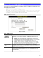
WPA-PSK Wireless Security
Figure 9: WPA-PSK
Data - WPA-PSK Screen
Security
System
WPA-PSK
PSK
Enter the PSK (network key). Data is encrypted using a key derived
from the network key. Other Wireless Stations must use the same
network key. The PSK must be from 8 to 63 characters in length.
WPA Encryption
The WPA-PSK standard allows different encryption methods to be
used. Select the desired option. Wireless Stations must use the same
encryption method.
Like WEP, data is encrypted before transmission. WPA is more
secure than WEP, and should be used if possible. WPA-PSK is the
version of WPA, which does NOT require a Radius Server on your
LAN.
21
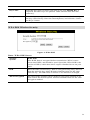
Trusted Wireless Stations (IAD-200W only)
This feature can be used to prevent unknown Wireless stations from using the Access Point.
This list has no effect unless the setting Allow access by trusted stations only is enabled.
To change the list of trusted wireless stations, use the Modify List button on the Access Control
screen. You will see a screen like the sample below.
Figure 10: Trusted Wireless Stations
Data - Trusted Wireless Stations
Trusted Wireless
Stations
This lists any Wireless Stations which you have designated as
“Trusted”.
Other Wireless
Stations
This list any Wireless Stations detected by the Access Point, which
you have not designated as "Trusted".
Name
The name assigned to the Trusted Wireless Station. Use this when
adding or editing a Trusted Station.
Address
The MAC (physical) address of the Trusted Wireless Station. Use
this when adding or editing a Trusted Station.
Buttons
<<
>>
Add a Trusted Wireless Station to the list (move from the "Other
Stations" list).
•
Select an entry (or entries) in the "Other Stations" list, and
click the " << " button.
•
Enter the Address (MAC or physical address) of the wireless
station, and click the "Add" button.
Delete a Trusted Wireless Station from the list (move to the "Other
Stations" list).
•
Select an entry (or entries) in the "Trusted Stations" list.
•
Click the " >> " button.
22
Edit
Use this to change an existing entry in the "Trusted Stations" list:
1. Select the Station in the Trusted Station list.
2. Click the Edit button. The address will be copied to the "Address" field, and the Add button will change to Update.
3. Edit the address (MAC or physical address) as required.
4. Click Update to save your changes.
Add (Update)
To add a Trusted Station which is not in the "Other Wireless
Stations" list, enter the required data and click this button.
When editing an existing Wireless Station, this button will change
from Add to Update.
Clear
Clear the Name and Address fields.
23
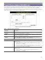
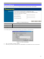
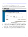
Password Screen
The password screen allows you to assign a password to the IAD-200 / IAD-200W.
Figure 11: Password Screen
Old Password
Enter the existing password in this field.
New password
Enter the new password here.
Verify password
Re-enter the new password here.
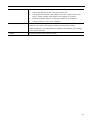
You will be prompted for the password when you connect, as shown below.
Figure 12: Password Dialog
•
The "User Name" is always admin
•
Enter the password for the IAD-200 / IAD-200W, as set on the Password screen above.
24
Chapter 4
PC Configuration
4
This Chapter details the PC Configuration required on the local ("Internal")
LAN.
Overview
For each PC, the following may need to be configured:
•
TCP/IP network settings
•
Internet Access configuration
•
Wireless configuration
Windows Clients
This section describes how to configure Windows clients for Internet access via the IAD-200 /
IAD-200W.
The first step is to check the PC's TCP/IP settings.
The IAD-200 / IAD-200W uses the TCP/IP network protocol for all functions, so it is essential
that the TCP/IP protocol be installed and configured on each PC.
TCP/IP Settings - Overview
If using the default IAD-200 / IAD-200W settings, and the default Windows
TCP/IP settings, no changes need to be made.
•
By default, the IAD-200 / IAD-200W will act as a DHCP Server, automatically providing
a suitable IP Address (and related information) to each PC when the PC boots.
•
For all non-Server versions of Windows, the default TCP/IP setting is to act as a DHCP
client.
If using a Fixed (specified) IP address, the following changes are required:
•
The Gateway must be set to the IP address of the Wireless VoIP ADSL Router.
•
The DNS should be set to the address provided by your ISP.
If your LAN has a Router, the LAN Administrator must reconfigure the Router itself. Refer to Chapter 6 - Advanced
Administration for details.
25
Checking TCP/IP Settings - Windows 9x/ME:
1.
Select Control Panel - Network. You should see a screen like the following:
Figure 13: Network Configuration
2.
3.
Select the TCP/IP protocol for your network card.
Click on the Properties button. You should then see a screen like the following.
Figure 14: IP Address (Win 95)
Ensure your TCP/IP settings are correct, as follows:
Using DHCP
To use DHCP, select the radio button Obtain an IP Address automatically. This is the default
Windows setting. Using this is recommended. By default, the IAD-200 / IAD-200W will act
as a DHCP Server.
Restart your PC to ensure it obtains an IP Address from the IAD-200 / IAD-200W.
Using "Specify an IP Address"
If your PC is already configured, check with your network administrator before making the
following changes:
26
•
On the Gateway tab, enter the IAD-200 / IAD-200W's IP address in the New Gateway
field and click Add, as shown below. Your LAN administrator can advise you of the IP
Address they assigned to the IAD-200 / IAD-200W.
Figure 15: Gateway Tab (Win 95/98)
•
On the DNS Configuration tab, ensure Enable DNS is selected. If the DNS Server Search
Order list is empty, enter the DNS address provided by your ISP in the fields beside the
Add button, then click Add.
Figure 16: DNS Tab (Win 95/98)
27
Checking TCP/IP Settings - Windows NT4.0
1.
Select Control Panel - Network, and, on the Protocols tab, select the TCP/IP protocol, as
shown below.
Figure 17: Windows NT4.0 - TCP/IP
2.
Click the Properties button to see a screen like the one below.
28
Figure 18: Windows NT4.0 - IP Address
3.
4.
Select the network card for your LAN.
Select the appropriate radio button - Obtain an IP address from a DHCP Server or Specify
an IP Address, as explained below.
Obtain an IP address from a DHCP Server
This is the default Windows setting. Using this is recommended. By default, the IAD-200 /
IAD-200W will act as a DHCP Server.
Restart your PC to ensure it obtains an IP Address from the IAD-200 / IAD-200W.
Specify an IP Address
If your PC is already configured, check with your network administrator before making the
following changes.
1.
The Default Gateway must be set to the IP address of the IAD-200 / IAD-200W. To set
this:
•
Click the Advanced button on the screen above.
•
On the following screen, click the Add button in the Gateways panel, and enter the
IAD-200 / IAD-200W's IP address, as shown in Figure 19 below.
•
If necessary, use the Up button to make the IAD-200 / IAD-200W the first entry in
the Gateways list.
29
Figure 19 - Windows NT4.0 - Add Gateway
2.
The DNS should be set to the address provided by your ISP, as follows:
•
Click the DNS tab.
•
On the DNS screen, shown below, click the Add button (under DNS Service Search
Order), and enter the DNS provided by your ISP.
Figure 20: Windows NT4.0 - DNS
30
Checking TCP/IP Settings - Windows 2000:
1.
2.
Select Control Panel - Network and Dial-up Connection.
Right - click the Local Area Connection icon and select Properties. You should see a
screen like the following:
Figure 21: Network Configuration (Win 2000)
3.
4.
Select the TCP/IP protocol for your network card.
Click on the Properties button. You should then see a screen like the following.
Figure 22: TCP/IP Properties (Win 2000)
31
5.
Ensure your TCP/IP settings are correct, as described below.
Using DHCP
To use DHCP, select the radio button Obtain an IP Address automatically. This is the default
Windows setting. Using this is recommended. By default, the IAD-200 / IAD-200W will act
as a DHCP Server.
Restart your PC to ensure it obtains an IP Address from the IAD-200 / IAD-200W.
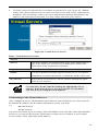
Using a fixed IP Address ("Use the following IP Address")
If your PC is already configured, check with your network administrator before making the
following changes.
•
Enter the IAD-200 / IAD-200W's IP address in the Default gateway field and click OK.
(Your LAN administrator can advise you of the IP Address they assigned to the IAD-200 /
IAD-200W.)
•
If the DNS Server fields are empty, select Use the following DNS server addresses, and
enter the DNS address or addresses provided by your ISP, then click OK.
32
Checking TCP/IP Settings - Windows XP
1.
2.
Select Control Panel - Network Connection.
Right click the Local Area Connection and choose Properties. You should see a screen
like the following:
Figure 23: Network Configuration (Windows XP)
3.
4.
Select the TCP/IP protocol for your network card.
Click on the Properties button. You should then see a screen like the following.
33
Figure 24: TCP/IP Properties (Windows XP)
5.
Ensure your TCP/IP settings are correct.
Using DHCP
To use DHCP, select the radio button Obtain an IP Address automatically. This is the default
Windows setting. Using this is recommended. By default, the IAD-200 / IAD-200W will act
as a DHCP Server.
Restart your PC to ensure it obtains an IP Address from the IAD-200 / IAD-200W.
Using a fixed IP Address ("Use the following IP Address")
If your PC is already configured, check with your network administrator before making the
following changes.
•
In the Default gateway field, enter the IAD-200 / IAD-200W's IP address and click OK.
Your LAN administrator can advise you of the IP Address they assigned to the IAD-200 /
IAD-200W.
•
If the DNS Server fields are empty, select Use the following DNS server addresses, and
enter the DNS address or addresses provided by your ISP, then click OK.
34
Internet Access
To configure your PCs to use the IAD-200 / IAD-200W for Internet access:
•
Ensure that the Internet connection is functional.
•
Use the following procedure to configure your Browser to access the Internet via the LAN,
rather than by a Dial-up connection.
For Windows 9x/ME/2000
1.
2.
3.
4.
5.
6.
7.
Select Start Menu - Settings - Control Panel - Internet Options.
Select the Connection tab, and click the Setup button.
Select "I want to set up my Internet connection manually, or I want to connect through a
local area network (LAN)" and click Next.
Select "I connect through a local area network (LAN)" and click Next.
Ensure all of the boxes on the following Local area network Internet Configuration screen
are unchecked.
Check the "No" option when prompted "Do you want to set up an Internet mail account
now?
Click Finish to close the Internet Connection Wizard.
Setup is now completed.
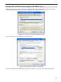
For Windows XP
1.
2.
3.
4.
5.
6.
7.
8.
9.
Select Start Menu - Control Panel - Network and Internet Connections.
Select Set up or change your Internet Connection.
Select the Connection tab, and click the Setup button.
Cancel the pop-up "Location Information" screen.
Click Next on the "New Connection Wizard" screen.
Select "Connect to the Internet" and click Next.
Select "Set up my connection manually" and click Next.
Check "Connect using a broadband connection that is always on" and click Next.
Click Finish to close the New Connection Wizard.
Setup is now completed.
Accessing AOL
To access AOL (America On Line) through the IAD-200 / IAD-200W, the AOL for Windows
software must be configured to use TCP/IP network access, rather than a dial-up connection.
The configuration process is as follows:
•
Start the AOL for Windows communication software. Ensure that it is Version 2.5, 3.0 or
later. This procedure will not work with earlier versions.
•
Click the Setup button.
•
Select Create Location, and change the location name from "New Locality" to "IAD-200 /
IAD-200W".
•
Click Edit Location. Select TCP/IP for the Network field. (Leave the Phone Number
blank.)
•
Click Save, then OK.
Configuration is now complete.
•
Before clicking "Sign On", always ensure that you are using the "IAD-200 / IAD-200W"
location.
35
Macintosh Clients
From your Macintosh, you can access the Internet via the IAD-200 / IAD-200W. The procedure is as follows.
1. Open the TCP/IP Control Panel.
2. Select Ethernet from the Connect via pop-up menu.
3. Select Using DHCP Server from the Configure pop-up menu. The DHCP Client ID field
can be left blank.
4. Close the TCP/IP panel, saving your settings.
Note:
If using manually assigned IP addresses instead of DHCP, the required changes are:
•
Set the Router Address field to the IAD-200 / IAD-200W's IP Address.
•
Ensure your DNS settings are correct.
Linux Clients
To access the Internet via the IAD-200 / IAD-200W, it is only necessary to set the IAD-200 /
IAD-200W as the "Gateway".
Ensure you are logged in as "root" before attempting any changes.
Fixed IP Address
By default, most Unix installations use a fixed IP Address. If you wish to continue using a
fixed IP Address, make the following changes to your configuration.
•
Set your "Default Gateway" to the IP Address of the IAD-200 / IAD-200W.
•
Ensure your DNS (Name server) settings are correct.
To act as a DHCP Client (recommended)
The procedure below may vary according to your version of Linux and X -windows shell.
1. Start your X Windows client.
2. Select Control Panel - Network
3. Select the "Interface" entry for your Network card. Normally, this will be called "eth0".
4. Click the Edit button, set the "protocol" to "DHCP", and save this data.
5. To apply your changes
•
Use the "Deactivate" and "Activate" buttons, if available.
•
OR, restart your system.
Other Unix Systems
To access the Internet via the IAD-200 / IAD-200W:
• Ensure the "Gateway" field for your network card is set to the IP Address of the IAD-200
/ IAD-200W.
•
Ensure your DNS (Name Server) settings are correct.
36
Wireless Station Configuration (IAD-200W only)
This section applies to all Wireless stations wishing to use the IAD-200W's Access Point,
regardless of the operating system which is used on the client.
To use the Wireless Access Point in the IAD-200W, each Wireless Station must have compatible settings, as follows:
Mode
The mode must be set to Infrastructure (rather than Ad-hoc)
Access points only operate in Infrastructure mode.
SSID (ESSID)
This must match the value used on the IAD-200W. The default value is
Wireless.
Note! The SSID is case sensitive.
Wireless
Security
By default, Wireless security on the IAD-200W is disabled.
•
If Wireless security remains disabled on the IAD-200W, all stations
must have wireless security disabled.
•
If Wireless security is enabled on the Wireless VoIP Gateway
(either WEP or WPA-PSK), each station must use the same settings
as the Wireless ADLS VoIP Gateway.
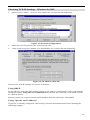
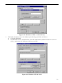
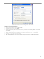
Wireless Configuration on Windows XP (IAD-200W only)
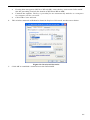
If using Windows XP to configure the Wireless interface on your PC, the configuration procedure is as follows:
1.
Open the Network Connections folder. (Start - Settings - Network Connections).
Figure 25: Network Connections (Windows XP)
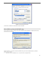
2.
3.
Right-click the Wireless Network Connection, check that it is enabled (menu option says
Disable, rather than Enable) and then select View Available Wireless Networks.
You will then see a list of wireless networks.
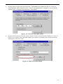
37
Figure 26 Wireless Networks (Windows XP)
If the "Broadcast SSID" setting on the IAD-200W has been
disabled, its SSID will NOT be listed. See the following section
"If the SSID is not listed" for details of dealing with this situation.
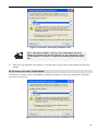
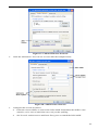
4.
The next step depends on whether or not Wireless security has been enabled on the IAD200W.
If Wireless Security is Disabled
If Wireless security on the IAD-200W is disabled, Windows will warn you that the Wireless
network is not secure.
Figure 27 Insecure Wireless Network (Windows XP)
38
To connect:
•
Check the checkbox Allow me to connect to the selected wireless network, even though it
is not secure.
•
The Connect button will then be available. Click the Connect button, and wait a few
seconds for the connection to be established.
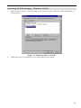
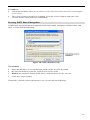
If using WEP Data Encryption
If WEP data encryption has been enabled on the IAD-200W, Windows will detect this, and
show a screen like the following.
Figure 28: WEP (Windows XP)
To connect:
•
Enter the WEP key, as set on the IAD-200W, in the Network Key field.
•
Re-enter the WEP key into the Confirm Network key field.
•
Disable the checkbox Enable IEEE 802.1x authentication for this network.
•
Click the Connect button.
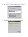
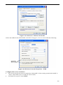
If this fails, click the Advanced button, to see a screen like the following:
39
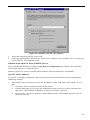
Figure 29: Advanced - Wireless Networks
Select the SSID for the IAD-200W, and click Configure, to see a screen like the following:
Figure 30: Wireless Network Properties - WEP
Configure this screen as follows:
•
Set Network Authentication to match the IAD-200W. (If the setting on the IAD-200W is
"Auto", then either Open or Shared can be used.)
•
For Data Encryption, select WEP.
40
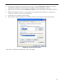
•
For the Network key and Confirm network key, enter the default key value used on the
IAD-200W. (Windows will determine if 64bit or 128bit encryption is used.)
•
The Key index must match the default key index on the IAD-200W. The default value is
1.
•
Ensure the options. The key is provided for me automatically and this is a computer-tocomputer (ad hoc) network are unchecked.
•
Click OK to save and close this dialog.
•
This wireless network will now be listed in Preferred Networks on the screen below.
Figure 31: Preferred Networks
Click OK to establish a connection to the IAD-200W.
41
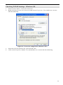
If using WPA-PSK Data Encryption (IAD-200W only)
If WPA-PSK data encryption has been enabled on the IAD-200W, it does not matter which
network is selected on the screen below. Just click the Advanced button.
Figure 32: Wireless Networks (Windows XP)
You will then see a screen like the example below.
Figure 33: Advanced - Wireless Networks
Select the SSID for the IAD-200W, and click Configure, to see a screen like the following:
42
Figure 34: Wireless Network Properties- WPA-PSK
Configure this screen as follows:
•
Set Network Authentication to WPA-PSK.
•
For Data Encryption, select TKIP.
•
For the Network key and Confirm network key, enter the network key (PSK) used on the
IAD-200W.
•
Ensure the option. This is a computer-to-computer (ad hoc) network is unchecked.
•
Click OK to save and close this dialog.
•
This wireless network will now be listed in Preferred Networks on the screen below.
43
Figure 35: Preferred Networks
Click OK to establish a connection to the IAD-200W.
If the SSID is not listed (IAD-200W only)
If the "Broadcast SSID" setting on the IAD-200W has been disabled, its SSID will NOT be
listed on the screen below.
Figure 36: Wireless Networks (Windows XP)
In this situation, you need to obtain the SSID from your network administrator, and then
follow this procedure:
1.
Click the Advanced button to see a screen like the example below.
44
Figure 37: Unlisted Wireless Network
2.
Click the Add button. You will see a screen like the example below.
Figure 38: Add Wireless Network
3.
Configure this screen as follows:
•
Enter the correct SSID, as used on the IAD-200W. Remember the SSID is casesensitive, so be sure to match the case, not just the spelling.
•
Set Network Authentication and Data Encryption to match the IAD-200W.
45
4.
•
If using data encryption (WEP or WPA-PSK), enter the key used on the IAD-200W.
See the preceding sections for details of WEP and WPA-PSK.
•
Uncheck the options. The key is provided for me automatically and this is a computerto-computer (ad hoc) network.
• Click OK to save and exit.
This wireless network will then be listed in Preferred Networks on the screen below.
Figure 39: Preferred Networks
5.
Click OK to establish a connection to the IAD-200W.
46
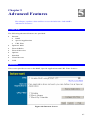
Chapter 5
Advanced Features
5
This Chapter explains when and how to use the IAD-200 / IAD-200W's
"Advanced" Features.
Overview
The following advanced features are provided:
•
Internet:
•
DMZ
•
Special Applications
•
URL filter
•
Dynamic DNS
•
Firewall Rules
•
Firewall Services
•
Options
•
Schedule
•
Virtual Servers
•
VoIP
Internet
This screen provides access to the DMZ, Special Applications and URL Filter features.
Figure 40: Internet Screen
47
DMZ
This feature, if enabled, allows the DMZ computer on your LAN to be exposed to all users on
the Internet.
•
This allows almost any application to be used on the "DMZ PC".
•
The "DMZ PC" will receive all "Unknown" connections and data.
•
If the DMZ feature is enabled, you must select the PC to be used as the "DMZ PC".
The "DMZ PC" is effectively outside the Firewall, making it
more vulnerable to attacks. For this reason, you should only
enable the DMZ feature when required.
Special Applications
If you use Internet applications which use non-standard connections or port numbers, you may
find that they do not function correctly because they are blocked by the IAD-200 / IAD200W's firewall. In this case, you can define the application as a "Special Application".
The Special Applications screen can be reached by clicking the Special Applications button on
the Internet screen.
You can then define your Special Applications. You will need detailed information about the
application; this is normally available from the supplier of the application.
Also, note that the terms "Incoming" and "Outgoing" on this screen refer to traffic from the
client (PC) viewpoint
Figure 41: Special Applications Screen
48
Data - Special Applications Screen
Checkbox
Use this to Enable or Disable this Special Application as required.
Name
Enter a descriptive name to identify this Special Application.
Incoming
Ports
Outgoing
Ports
•
Type - Select the protocol (TCP or UDP) used when you receive data
from the special application or service. (Note: Some applications use
different protocols for outgoing and incoming data).
•
Start - Enter the beginning of the range of port numbers used by the
application server, for data you receive. If the application uses a single
port number, enter it in both the "Start" and "Finish" fields.
•
Finish - Enter the end of the range of port numbers used by the application server, for data you receive.
•
Type - Select the protocol (TCP or UDP) used when you send data to
the remote system or service.
•
Start - Enter the beginning of the range of port numbers used by the
application server, for data you send to it. If the application uses a single port number, enter it in both the "Start" and "Finish" fields.
•
Finish - Enter the end of the range of port numbers used by the application server, for data you send to it. If the application uses a single port
number, enter it in both the "Start" and "Finish" fields.
Using a Special Application
•
Configure the Special Applications screen as required.
•
On your PC, use the application normally. Remember that only one (1) PC can use each
Special application at any time. Also, when 1 PC is finished using a particular Special Application, there may need to be a "Time-out" before another PC can use the same Special
Application. The "Time-out" period may be up to 3 minutes.
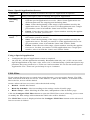
URL Filter
If you want to limit access to certain sites on the Internet, you can use this feature. The URL
filter will check each Web site access. If the address, or part of the address, is included in the
block site list, access will be denied.
On the Advanced Internet screen, select the desired setting:
•
Disable - disable this feature.
•
Block By Schedule - block according to the settings on the Schedule page.
•
Block Always - allow blocking all of the time, independent of the Schedule page.
Click the Configure URL Filter button to open the URL Filter screen, allowing you to create
or modify the filter strings which determine which sites will be blocked.
The URL Filter screen is displayed when the Configure URL Filter button on the Advanced
Internet screen is clicked.
49
Figure 42: URL Filter Screen
Data - URL Filter Screen
Current Filter Strings
Current Filter
Strings
Add Filter String
The list contains the current list of items to block.
•
To add to the list, use the "Add" option below.
•
To delete an entry, select it and click Delete button.
•
To delete all entries, click the Delete All button.
To add to the current list, type the word or domain name you want to
block into the field provided, then click the Add button.
Filter strings should be as specific as possible. Otherwise, you may
block access to many more sites than intended.
50
Trusted PC
Allow Trusted
PC
Enable this to allow one computer to have unrestricted access to the
Internet. For this PC, the URL filter will be ignored.
If enabled, you must select the PC to be the trusted PC.
Trusted PC
Select the PC to be the Trusted PC.
51
Dynamic DNS (Domain Name Server)
This free service is very useful when combined with the Virtual Server feature. It allows
Internet users to connect to your Virtual Servers using a URL, rather than an IP Address.
This also solves the problem of having a dynamic IP address. With a dynamic IP address, your
IP address may change whenever you connect, which makes it difficult to connect to you.
DDNS Services work as follows:
1.
2.
3.
4.
5.
You must register for the service at one of the listed DDNS Service providers.
After registration, use the Service provider's normal procedure to obtain your desired
Domain name.
Enter your DDNS data on the IAD-200 / IAD-200W's DDNS screen, and enable the
DDNS feature.
The IAD-200 / IAD-200W will then automatically ensure that your current IP Address is
recorded at the DDNS service provider's Domain Name Server.
From the Internet, users will be able to connect to your Virtual Servers (or DMZ PC)
using your Domain name, as shown on this screen.
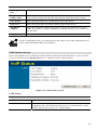
Dynamic DNS Screen
Select Advanced on the main menu, then Dynamic DNS, to see a screen like the following:
Figure 43: DDNS Screen
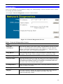
Data - Dynamic DNS Screen
DDNS Service
Use a Dynamic
DNS Service
Use this to enable or disable the DDNS feature as required.
Service Provider
Select the desired DDNS Service provider.
Web Site
Click this button to open a new window and connect to the Web site
of the selected DDNS service provider.
52
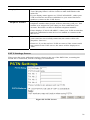
DDNS Data
Host Name
Enter the domain name allocated to you by the DDNS Service. If you
have more than one name, enter the name you wish to use.
User Name
Enter your Username for the DDNS Service. (TZO.com uses your Email address.)
Password
Enter your current password for the DDNS Service. (TZO.com calls
this a key.)
Domain Name
Enter the domain name allocated to you by the DDNS Service. If you
have more than one name, enter the name you wish to use.
DDNS Status
•
This message is returned by the DDNS Server.
•
Normally, this message should be "Update successful"
•
If the message indicates some problem, you need to connect to
the DDNS Service provider and correct this problem.
53
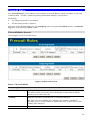
Firewall Rules
The Firewall Rules screen allows you to define "Firewall Rules" which can allow or prevent
certain traffic. "Traffic" means incoming connection attempts, not packets.
By default:
•
All Outgoing traffic is permitted.
•
All Incoming traffic is denied.
Because of this default behavior, any Outgoing rules will generally Block traffic, and Incoming rules will generally Allow traffic.
Firewall Rules Screen
An example screen is shown below.
Figure 44 Firewall Screen
Data - Firewall Rules
Incoming Rules
#
For the default rule, this will display "Default".
For rules which you create, this will display a radio button which
allows you to select the rule.
Enable
Indicates whether or not the rule is currently enabled.
For rules you have added, this column will contain a checkbox,
allowing you to easily enable or disable the rule. (Click "Save" after
making any changes.)
Service Name
The Service covered by this rule.
54
Action
The action performed on connections which are covered by this rule.
LAN Server
The PC or Server on your LAN to which traffic covered by this rule
will be sent.
WAN Users
The WAN IP address or addresses covered by this rule.
Log
Indicates whether or not connections covered by this rule should be
logged.
Buttons
Use the Add button to create a new rule.
The other buttons - Edit, Move, or Delete - require that a rule be
selected first. Use the radio buttons in the left column to select the
desired rule.
Outgoing Rules
#
For the default rule, this will display "Default".
For rules which you create, this will display a radio button which
allows you to select the rule.
Enable
Indicates whether or not the rule is currently enabled.
For rules you have added, this column will contain a checkbox,
allowing you to easily enable or disable the rule. (Click "Save" after
making any changes.)
Service Name
The Service covered by this rule.
Action
The action performed on connections which are covered by this rule.
LAN Users
The LAN PC or PCs covered by this rule.
WAN Servers
The WAN IP address or addresses covered by this rule.
Log
Indicates whether or not connections covered by this rule should be
logged.
Buttons
Use the Add button to create a new rule.
The other buttons - Edit, Move, or Delete - require that a rule be
selected first. Use the radio buttons in the left column to select the
desired rule.
55
Incoming Rules (Inbound Services)
This screen is displayed when the "Add" or "Edit" button for Incoming Rules is clicked.
Figure 45: Inbound Services Screen
Data - Incoming Rules Screen
Inbound Services
Service
Select the desired Service. This determines which packets are covered by
this rule. If necessary, you can define a new Service on the "Services"
screen, by defining the protocols and port numbers used by the Service.
Action
Select the desired action for packets covered by this rule:
•
ALLOW always
•
ALLOW by schedule, otherwise Block
•
BLOCK always
•
BLOCK by schedule, otherwise Allow
Note:
•
Any inbound traffic which is not allowed by rules you create will be
blocked by the Default rule.
•
BLOCK rules are only useful if the traffic is already covered by an
ALLOW rule. (That is, you wish to block a sub-set of traffic which
is currently allowed by another rule.)
•
To define the Schedule used in these selections, use the "Schedule"
screen.
Send to
LAN Server
Select the PC or Server on your LAN which will receive the inbound
traffic covered by this rule.
WAN Users
These settings determine which packets are covered by the rule, based
on their source (WAN) IP address. Select the desired option:
•
Any - All IP addresses are covered by this rule.
•
Address range - If this option is selected, you must enter the
desired values in the "Single/Start" and "Finish" fields to determine
the address range.
•
Single address - Enter the required address in the "Single/Start"
fields.
56
Log
This determines whether packets covered by this rule are logged. Select
the desired action.
•
Always - always log traffic considered by this rule, whether it
matches or not. (This is useful when debugging your rules.)
•
Never - never log traffic considered by this rule, whether it matches
or not.
•
Match - Log traffic only it matches this rule. (The action is determined by this rule.)
•
Not Match - Log traffic which is considered by this rule, but does
not match (The action is NOT determined by this rule.)
Outgoing Rules (Outbound Services)
This screen is displayed when the "Add" or "Edit" button for Outgoing Rules is clicked.
Figure 46: Outbound Services Screen
Data - Outbound Rules Screen
Outbound Services
Service
Select the desired Service or application to be covered by this rule. If the
desired service or application does not appear in the list, you must define
it using the "Services" menu option
Action
Select the desired action for packets covered by this rule:
•
BLOCK always
•
BLOCK by schedule, otherwise Allow
•
ALLOW always
•
ALLOW by schedule, otherwise Block
Note:
•
Any outbound traffic which is not blocked by rules you create will
be allowed by the Default rule.
•
ALLOW rules are only useful if the traffic is already covered by a
57
BLOCK rule. (That is, you wish to allow a subset of traffic which is
currently blocked by another rule.)
•
LAN Users
To define the Schedule used in these selections, use the "Schedule"
screen.
Select the desired option to determine which PCs are covered by this
rule:
•
Any - All PCs are covered by this rule.
•
Single PC - Only the selected PC is covered by this rule.
If selected, you must select the PC.
PC - If using Single PC above, select the PC or Server on your LAN
which will be covered by this rule.
WAN Users
Log
These settings determine which packets are covered by the rule, based
on their source (WAN) IP address. Select the desired option:
•
Any - All IP addresses are covered by this rule.
•
Address range - If this option is selected, you must enter the "Start"
and "Finish" fields.
•
Single address - Enter the required address in the "Single/Start"
fields.
This determines whether packets covered by this rule are logged. Select
the desired action.
•
Always - always log traffic considered by this rule, whether it
matches or not. (This is useful when debugging your rules.)
•
Never - never log traffic considered by this rule, whether it matches
or not.
•
Match - Log traffic only it matches this rule. (The action is determined by this rule.)
•
Not Match - Log traffic which is considered by this rule, but does
not match (The action is NOT determined by this rule.)
58
User-defined Services
Services are used when creating Firewall Rules.
If you wish to create a firewall rule, but the required service is not listed in the "Service" list,
you can use this feature to define the required service or services. Once created, these services
will be listed in the "Service" list, and can be used when creating Firewall Rules.
Figure 47: Add Services Screen
Data - User-defined Services
Services
Existing Services
This lists any Services you have defined. If you have not defined any
Services, this list will be empty.
Once you define some services, they will be listed here, and also
shown in the Service list used to create Firewall rules. (User-defined
services are at the end of the list, after the pre-defined services.)
Add
Use this to open a sub-screen where you can add a new service.
Edit
To modify a service, select it, and then click this button.
Delete
Use this button to delete the selected service. You can delete any
services you have defined.
59
Add/Edit Service
This screen is displayed when the Add or Edit button on the Services screen is clicked.
Figure 48 : Add/Edit Service
Data - Add/Edit Service
Services
Name
If editing, this shows the current name of the Service.
If adding a new service, this will be blank, and you should enter a
suitable name.
Type
Select the protocol used by the Service.
Start Port
Enter the beginning of the port range used by the Service.
Finish Port
Enter the end of the port range used by the Service.
60
Options
This screen allows advanced users to enter or change a number of settings. For normal operation, there is no need to use this screen or change any settings.
An example Options screen is shown below.
Figure 49: Options Screen
Data - Options Screen
Internet
Respond to Ping
MTU Size
•
If checked, the Wireless Router will respond to Ping (ICMP)
packets received from the Internet.
•
If not checked, Ping (ICMP) packets from the Internet will be
ignored. Disabling this option provides a slight increase in security.
Enter a value between 1 and 1500.
Note: MTU (Maximum Transmission Unit) size should only be
changed if advised to do so by Technical Support.
UPnP
UPnP
•
UPnP (Universal Plug and Play) allows automatic discovery and
configuration of equipment attached to your LAN. UPnP is by
supported Windows ME, XP, or later.
•
If Enabled, this device will be visible via UPnP.
•
If Disabled, this device will not be visible via UPnP.
Advertisement
Period
Enter the desired value, in minutes. The valid range is from 1 to 1440.
Advertisement
Time to Live
Enter the desired value, in hops. The valid range is from 1 to 255.
61
Schedule
This Schedule can be used for the Firewall Rules and the URL filter.
Figure 50: Schedule Screen
Data - Schedule Screen
Schedule
Day
Each day of the week can scheduled independently.
Session 1
Session 2
Two (2) separate sessions or periods can be defined. Session 2 can
be left blank if not required.
Start Time
Enter the start using a 24 hr clock.
Finish Time
Enter the finish time using a 24 hr clock.
Local Time
Time Zone
In order to display your local time correctly, you must select your
"Time Zone" from the list.
Adjust for Daylight Savings Time
If your region uses Daylight Savings Time, you must manually
check "Adjust for Daylight Savings Time" at the beginning of the
62
light Savings Time
adjustment period, and uncheck it at the end of the Daylight Savings
period.
Use this NTP
Server
If you prefer to use a particular NTP server as the primary NTP
server, check the checkbox "Use this NTP Server" and enter the
Server's IP address in the fields provided.
If this setting is not enabled, the default NTP Servers are used.
Current Time
This displays the current time on the IAD-200 / IAD-200W, at the
time the page is loaded.
63
Virtual Servers
This feature, sometimes called Port Forwarding, allows you to make Servers on your LAN
accessible to Internet users. Normally, Internet users would not be able to access a server on
your LAN because:
•
Your Server does not have a valid external IP Address.
•
Attempts to connect to devices on your LAN are blocked by the firewall in this device.
The "Virtual Server" feature solves these problems and allows Internet users to connect to your
servers, as illustrated below.
Figure 51: Virtual Servers
IP Address seen by Internet Users
Note that, in this illustration, both Internet users are connecting to the same IP Address, but
using different protocols.
To Internet users, all virtual Servers on your LAN have the same IP Address. This IP
Address is allocated by your ISP.
This address should be static, rather than dynamic, to make it easier for Internet users to
connect to your Servers.
However, you can use the DDNS (Dynamic DNS) feature to allow users to connect to your
Virtual Servers using a URL, instead of an IP Address.
Virtual Servers Screen
•
The "Virtual Servers" feature allows Internet Users to access PCs on your LAN.
•
The PCs must be running the appropriate Server Software.
•
For Internet Users, ALL of your Servers have the same IP address. This IP address is
allocated by your ISP.
64
•
To make it easier for Internet users to connect to your Servers, you can use the "DDNS"
feature. This allows Internet users to connect to your Servers with a URL, rather than an
IP address. This technology works even if your ISP allocates dynamic IP addresses (IP
address is allocated upon connection, so it may change each time you connect).
Figure 52: Virtual Servers Screen
Data - Virtual Servers Screen
Servers
Servers
This lists a number of common Server types. If the desired Server
type is not listed, you can create a Firewall Rule to achieve the
same effect as the Virtual Server function.
Properties
Enable
Use this to Enable or Disable support for this Server, as required.
If Enabled, you must select the PC to which this traffic will be sent.
PC (Server)
Select the PC for this Server. The PC must be running the appropriate Server software.
For each entry, the PC must be running the appropriate Server
software. If the desired Server type is not listed, you can define
your own Servers, using the Firewall Rules.
Connecting to the Virtual Servers
Once configured, anyone on the Internet can connect to your Virtual Servers. They must use
the Internet IP Address (the IP Address allocated to you by your ISP).
e.g.
http://203.70.212.52
ftp://203.70.212.52
It is more convenient if you are using a Fixed IP Address from your ISP, rather than Dynamic.
However, you can use the Dynamic DNS feature to allow users to connect to your Virtual
Servers using a URL, rather than an IP Address.
65
Note:
From the Internet, ALL Virtual Servers have the IP Address allocated by your ISP.
66
VoIP
To use the VoIP feature requires the following:
•
Standard Phone
A standard analogue Phone must be connected to the Phone socket.
•
VoIP (SIP Server) Account
Generally, you will need a SIP Server account from a VoIP service provider. The account
details should include the SIP Register address, SIP Proxy address, SIP register port, SIP
Proxy port, username, password, and telephone number. (Many providers use the same
proxy server for both Proxy and Register.)
•
VoIP Configuration
•
Your VoIP service provider may perform the configuration for you.
•
If not, refer to the following sections, which describe how to configure the Wireless
VoIP Gateway.
Refer to Chapter 7 - Operation and Status for details on using VoIP once configuration has
been completed.
VoIP Setup Screen
The VoIP setup screen is not on the menu; the VoIP link on the menu displays the VoIP Status
screen, described later in this chapter.
To view the VoIP Setup Screen:
1.
2.
Connect to the IAD-200 / IAD-200W using its IP address and the path to the VoIP Setup
screen ( /set_voip.htm ). For example, if the default IP address has not been changed, use
the following:
http://192.168.0.1/set_voip.htm
You will see the VoIP Settings screen, like the example below. This screen allows input of
the data necessary to establish a connection to the SIP Server.
67
Figure 53: VoIP Settings
VoIP Settings
Local Service
SIP Local Port
This port is used for peer-to-peer (direct) connections to another device,
when no SIP server is used.
Normally, this should be left at the default value. Any other devices you
wish to connect to must use the same port number.
SIP - Line 1
Enable Line1
Check this if you wish to connect to a SIP Server. If enabled, you must
provide the following data.
SIP Proxy
address
Enter the address of the SIP Proxy (Server) used by your VoIP provider.
SIP Proxy port
Enter the port used for connections to the Server above.
SIP register
address
Enter the address of the SIP Register (Server) used by your VoIP provider. This may be the same server as the "Proxy" above.
68
SIP register
port
Enter the port used for "Register" connections to the Server above.
Register
Expiry Time
This sets the "Idle Timeout" for the SIP Server Login. An Idle connection will be terminated after this time period. Enter the desired value.
User Name
Enter the login name for connections to the SIP Server.
Password
Enter the password associated with the login name above.
Telephone
Number
Enter the telephone number provided to you by the VoIP Service provider. If you have a range of numbers, enter the number you wish to use
for this line.
Display Name
This name is used by the SIP Server, and may be visible to callers.
For the comparable issue, you should set up the same voice codec and packet size
on the IAD-200/200W and your IP phone.
VoIP Status Screen
This screen allows you to check the status of the connection to the SIP Server. It is accessed
via the VoIP link on the Advanced menu. A sample screen is shown below.
Figure 54: VoIP Status Screen
VoIP Status
Line 1
VoIP Status
This indicates if VoIP is enabled or disabled.
Line Status
Sometimes called "Hook Status"; this indicates the status on the
telephone line. ON indicates the receiver is "on-the-hook", while
OFF indicates the receiver is "off-the-hook".
69
Display Name
This is the name you chose when you first opened your account.
Your "Display Name" will be visible to other individuals with
caller ID.
If your display name appears as "UNAVAILABLE", either your
VoIP account has not been established or your router has been
unable to connect to the VoIP Server.
Telephone Number
The telephone number associated with this line. This is the
telephone number other people will use when they call you. This
number was assigned to you when you first established your
account. Each line can have a different telephone number.
If this displays "UNAVAILABLE", either your VoIP account has
not been established or this device was unable to connect to the
SIP server.
Registration Status
This shows the status of the connection to the SIP Server. When
your router has successfully connected, the status will be displayed as "Success".
However, if you do not have VoIP account or if the router could
not connect to the VoIP server, the status will be displayed as
"Idle".
PSTN Settings Screen
This screen has some additional settings related to the use of the PSTN line, assuming the
PSTN line is connected, which is strongly recommended.
Figure 55: PSTN Screen
70
PSTN Settings
PSTN Relay
PSTN Prefix
The PSTN Relay allows certain calls to be diverted to the
PSTN link, even though VoIP is working properly.
This PSTN prefix means that any number beginning with this
prefix will be diverted to PSTN (the prefix itself is deleted,
then the remainder of the number is dialed via PSTN).
•
If the prefix is a single character, that character must be *
•
If the prefix is multiple characters, all characters after the
1st character must be digits. The 1st char character can be *
or a digit.
Note: When dialing, do not wait for a 2nd dial tone for the
PSTN; there is no 2nd dial tone. Just dial the PSTN prefix and
the desired phone number.
PSTN Fixed Relay
This provides another method of diverting calls to the PSTN
link. Any Telephone numbers listed in this table will always be
dialed via PSTN.
This feature should be used to direct emergency numbers to the
PSTN.
PSTN Rollover
Use PSTN…
If enabled, then when VoIP is unavailable, all calls from the
handset will be sent via PSTN. (This is the same effect as
occurs when the power is off.) However, note that VoIP phone
numbers (beginning with are often unreachable via PSTN.
Normally, this setting should be Enabled.
71
Chapter 6
Advanced Administration
6
This Chapter explains the settings available via the "Administration" section
of the menu.
Overview
Normally, it is not necessary to use these screens, or change any settings. These screens and
settings are provided to deal with non-standard situations, or to provide additional options for
advanced users.
The available settings and features are:
PC Database
This is the list of PCs shown when you select the "DMZ PC" or a
"Virtual Server". This database is maintained automatically, but
you can add and delete entries for PCs which use a Fixed (Static)
IP Address.
Config File
Backup or restore the configuration file for the IAD-200 / IAD200W. This file contains all the configuration data.
Logging & Email
View or clear all logs, set E-Mailing of log files and alerts.
Diagnostics
Perform a Ping or DNS Lookup.
Remote Admin
Allow settings to be changed from the Internet.
Routing
Only required if your LAN has other Routers or Gateways.
Upgrade Firmware
Upgrade the Firmware (software) installed in your IAD-200 /
IAD-200W.
72
PC Database
The PC Database is used whenever you need to select a PC (e.g. for the "DMZ" PC).
•
It eliminates the need to enter IP addresses.
•
Also, you do not need to use fixed IP addresses on your LAN.
However, if you do use a fixed IP address on some devices on your LAN, you should enter
details of each such device into the PC database, using the PC Database screen.
PC Database Screen
An example PC Database screen is shown below.
Figure 56: PC Database
•
PCs which are "DHCP Clients" are automatically added to the database, and updated as
required.
•
By default, non-Server versions of Windows act as "DHCP Clients"; this setting is called
"Obtain an IP Address automatically".
•
The IAD-200 / IAD-200W uses the "Hardware Address" to identify each PC, not the
name or IP address. The "Hardware Address" can only change if you change the PC's
network card or adapter.
•
This system means you do NOT need to use Fixed (static) IP addresses on your LAN.
However, you can add PCs using Fixed (static) IP Addresses to the PC database if required.
73
Data - PC Database Screen
Known PCs
This lists all current entries. Data displayed is name (IP Address) type.
The "type" indicates whether the PC is connected to the LAN.
Name
If adding a new PC to the list, enter its name here. It is best if this
matches the PC's "hostname".
IP Address
Enter the IP Address of the PC. The PC will be sent a "ping" to determine its hardware address. If the PC is not available (not connected, or
not powered On) you will not be able to add it.
Buttons
Add
This will add the new PC to the list. The PC will be sent a "ping" to
determine its hardware address. If the PC is not available (not connected, or not powered On) you will not be able to add it.
Delete
Delete the selected PC from the list. This should be done in 2 situations:
•
The PC has been removed from your LAN.
•
The entry is incorrect.
Refresh
Update the data on screen.
Generate Report
Display a read-only list showing full details of all entries in the PC
database.
Advanced
Administration
View the Advanced version of the PC database screen - PC Database
(Admin). See below for details.
74
PC Database - Advanced
This screen is displayed if the "Advanced Administration" button on the PC Database is
clicked. It provides more control than the standard PC Database screen.
Figure 57: PC Database (Admin)
Data - Advanced PC Database
Known PCs
This lists all current entries. Data displayed is name (IP Address) type.
The "type" indicates whether the PC is connected to the LAN.
PC Properties
Name
If adding a new PC to the list, enter its name here. It is best if this
matches the PC's "hostname".
75
IP Address
MAC Address
Select the appropriate option:
•
Automatic - The PC is set to be a DHCP client (Windows: "Obtain an IP address automatically"). The IAD-200 / IAD-200W will
allocate an IP address to this PC when requested to do so. The IP
address could change, but normally won't.
•
DCHP Client - Reserved IP Address - Select this if the PC is set
to be a DCHP client, and you wish to guarantee that the IAD-200 /
IAD-200W will always allocate the same IP Address to this PC.
Enter the required IP address.
•
Fixed IP Address - Select this if the PC is using a Fixed (Static)
IP address. Enter the IP address allocated to the PC. (The PC itself
must be configured to use this IP address.)
Select the appropriate option
•
Automatic discovery - Select this to have the IAD-200 / IAD200W contact the PC and find its MAC address. This is only possible if the PC is connected to the LAN and powered On.
•
MAC address is - Enter the MAC address on the PC. The MAC
address is also called the "Hardware Address", "Physical Address", or "Network Adapter Address". The IAD-200 / IAD-200W
uses this to provide a unique identifier for each PC. Because of
this, the MAC address can NOT be left blank.
Buttons
Add as New
Entry
Add a new PC to the list, using the data in the "Properties" box.
If "Automatic discovery" (for MAC address) is selected, the PC will be
sent a "ping" to determine its hardware address. This will fail unless
the PC is connected to the LAN, and powered on.
Update Selected
PC
Update (modify) the selected PC, using the data in the "Properties"
box.
Clear Form
Clear the "Properties" box, ready for entering data for a new PC.
Refresh
Update the data on screen.
Generate Report
Display a read-only list showing full details of all entries in the PC
database.
Standard Screen
Click this to view the standard PC Database screen.
76
Config File
This feature allows you to download the current settings from the IAD-200 / IAD-200W, and
save them to a file on your PC.
You can restore a previously-downloaded configuration file to the IAD-200 / IAD-200W, by
uploading it to the IAD-200 / IAD-200W.
This screen also allows you to set the IAD-200 / IAD-200W back to its factory default configuration. Any existing settings will be deleted.
An example Config File screen is shown below.
Figure 58: Config File Screen
Data - Config File Screen
Backup Config
Use this to download a copy of the current configuration, and store the
file on your PC. Click Download to start the download.
Restore Config
This allows you to restore a previously-saved configuration file back to
the IAD-200 / IAD-200W.
Click Browse to select the configuration file, then click Restore to
upload the configuration file.
WARNING !
Uploading a configuration file will destroy (overwrite) ALL of the
existing settings.
Default Config
Clicking the Factory Defaults button will reset the IAD-200 / IAD200W to its factory default settings.
WARNING !
This will delete ALL of the existing settings.
77
Logs
The Logs record various types of activity on the IAD-200 / IAD-200W. This data is useful for
troubleshooting, but enabling all logs will generate a large amount of data and adversely affect
performance.
Since only a limited amount of log data can be stored in the IAD-200 / IAD-200W, log data
can also be E-mailed to your PC. Use the E-mail screen to configure this feature.
Figure 59: Logs Screen
Data - Logs Screen
Logs
Current Time
The current time on the IAD-200 / IAD-200W is displayed.
Log Data
Current log data is displayed in this panel.
78
Buttons
There are three (3) buttons
•
Refresh - Update the log data.
•
Clear Log - Clear the log, and restart it. This makes new
messages easier to read.
•
Send Log - E-mail the log immediately. This is only functional if the E-mail screen has been configured.
Logs
Include (Checkboxes)
Use these checkboxes to determine which events are included in
the log. Checking all options will increase the size of the log, so it
is good practice to disable any events which are not really required.
•
Attempted access to blocked sites - If checked, attempted
Internet accesses which were blocked are logged.
•
Connections to the Web-based interface of this Router - If
checked, this will log connections TO this Router, rather than
through this Router to the Internet.
•
Router operation - If checked, other Router operations (not
covered by the selections above) will be logged.
•
Known DoS attacks and Port Scans - If checked, Denial of
Service attacks, as well as port scans, will be logged.
Syslog
Disable
Data is not sent to a Syslog Server.
Broadcast on LAN
The Syslog data is broadcast, rather than sent to a specific Syslog
server. Use this if your Syslog Server does not have a fixed IP
address.
Syslog
If your Syslog server has a fixed IP address, select this option,
and enter the IP address of your Syslog server.
79
E-mail
This screen allows you to E-mail Logs and Alerts. A sample screen is shown below.
Figure 60: E-mail Screen
Data - E-mail Screen
E-Mail Notification
Turn E-mail
Notification on
Check this box to enable this feature. If enabled, the E-mail address
information (below) must be provided.
Send to this Email address
Enter the E-mail address the Log is to be sent to. The E-mail will also
show this address as the Sender's address.
Outgoing (SMTP)
Mail Server
Enter the address or IP address of the SMTP (Simple Mail Transport
Protocol) Server you use for outgoing E-mail.
My SMTP Mail
Server requires
authentication
To stop spanners, many SMTP mail servers require you to log in to
send mail. In this case, enable this checkbox, and enter the login
information (User name and Password) in the fields below.
User Name
If you have enabled "My SMTP Mail Server requires authentication"
above, enter the User Name required to login to your SMTP Server.
80
Password
If you have enabled "My SMTP Mail Server requires authentication"
above, enter the password required to login to your SMTP Server.
E-mail Alerts
Send E-mail alerts
immediately
You can choose to have alerts E-mailed to you, by checking the
desired checkboxes. The Broadband ADSL Router can send an
immediate alert when it detects a significant security incident such as
•
A known hacker attack is directed at your IP address
•
A computer on the Internet scans your IP address for open ports
•
Someone on your LAN (Local Area Network) tries to visit a
blocked site.
E-mail Logs
Send Logs
Select the desired option for sending the log by E-mail.
•
Never (default) - This feature is disabled; Logs are not sent.
•
When log is full - The time is not fixed. The log will be sent
when the log is full, which will depend on the volume of traffic.
•
Hourly, Daily, Weekly... - The log is sent on the interval
specified.
•
If Daily is selected, the log is sent at the time specified.
Select the time of day you wish the E-mail to be sent.
•
If Weekly is selected, the log is sent once per week, on the
specified day, at the specified time.
Select the day and the time of day you wish the E-mail to be
sent.
Note:
If the log is full before the time specified to send it, it will be sent
regardless of the day and time specified.
81
Diagnostics
This screen allows you to perform a "Ping" or a "DNS lookup". These activities can be useful
in solving network problems.
An example Network Diagnostics screen is shown below.
Figure 61: Network Diagnostics Screen
Data - Network Diagnostics Screen
Ping
Ping this
IP Address
Enter the IP address you wish to ping. The IP address can be on your
LAN, or on the Internet. Note that if the address is on the Internet,
and no connection currently exists, you could get a "Timeout" error.
In that case, wait a few seconds and try again.
Ping Button
After entering the IP address, click this button to start the "Ping"
procedure. The results will be displayed in the Ping Results pane.
DNS Lookup
Internet name
Enter the Domain name or URL for which you want a DNS (Domain
Name Server) lookup. Note that if the address in on the Internet, and
no connection currently exists, you could get a "Timeout" error. In
that case, wait a few seconds and try again.
Lookup Button
After entering the Domain name/URL, click this button to start the
"DNS Lookup" procedure.
Routing
Display
Click this button to display the internal routing table. This information can be used by Technical Support and other staff who
understand Routing Tables.
82
Remote Administration
If enabled, this feature allows you to manage the IAD-200 / IAD-200W via the Internet.
Figure 62: Remote Administration Screen
Data - Remote Administration Screen
Remote Administration
Enable Remote
Management
Check to allow administration/management via the Internet. (To
connect, see below).
If Disabled, this device will ignore Administration connection
attempts from the Internet.
Current
IP Address
This is the current address you will use when accessing this device
from the Internet. To connect, see details and an example below.
Port Number
Enter a port number between 1 and 65535. The default for HTTP
(Web) connections is port 80, but using port 80 will prevent the use
of a Web "Virtual Server" on your LAN. So using a different port
number is recommended. The default value is 8080.
The port number must be specified in your Browser when you
connect. See the following section for details.
Access Permission
Allow Remote
Access
Select the desired option.
•
Everyone - allow access by everyone on the Internet.
•
Only This Computer - allow access by only one IP address.
Enter the desired IP address.
•
IP Address Range - allow access from a range of IP addresses
on the Internet. Enter a beginning and ending IP address to define the allowed range.
83
For security, you should restrict access to as few external IP addresses as practical.
To connect from a remote PC via the Internet
1.
2.
Ensure your Internet connection is established, and start your Web Browser.
In the "Address" bar, enter "HTTP://" followed by the Internet IP Address of the IAD-200
/ IAD-200W. If the port number is not 80, the port number is also required. (After the IP
Address, enter ":" followed by the port number.)
e.g.
HTTP://123.123.123.123:8080
This example assumes the WAN IP Address is 123.123.123.123, and the port number is
8080.
3. You will then be prompted for the login name and password for this device.
84
Routing
Overview
•
If you don't have other Routers or Gateways on your LAN, you can ignore the "Routing"
page completely.
•
If the IAD-200 / IAD-200W is only acting as a Gateway for the local LAN segment,
ignore the "Routing" page even if your LAN has other Routers.
•
If your LAN has a standard Router (e.g. Cisco) on your LAN, and the IAD-200 / IAD200W is to act as a Gateway for all LAN segments, enable RIP (Routing Information Protocol) and ignore the Static Routing table.
•
If your LAN has other Gateways and Routers, and you wish to control which LAN segments use each Gateway, do NOT enable RIP (Routing Information Protocol). Configure
the Static Routing table instead. (You also need to configure the other Routers.)
•
If using Windows 2000 Data center Server as a software Router, enable RIP on the IAD200 / IAD-200W, and ensure the following Windows 2000 settings are correct:
•
Open Routing and Remote Access
•
In the console tree, select Routing and Remote Access , [server name], IP Routing,
RIP
•
In the "Details" pane, right-click the interface you want to configure for RIP version 2,
and then click "Properties".
•
On the "General" tab, set Outgoing packet protocol to "RIP version 2 broadcast", and
Incoming packet protocol to "RIP version 1 and 2".
Routing Screen
The routing table is accessed by the Routing link on the Administration menu.
Using this Screen
Generally, you will use either RIP (Routing Information Protocol) OR the Static Routing Table,
as explained above, although is it possible to use both methods simultaneously.
Static Routing Table
•
If RIP is not used, an entry in the routing table is required for each LAN segment on your
Network, other than the segment to which this device is attached.
•
The other Routers must also be configured. See Configuring Other Routers on your LAN
later in this chapter for further details and an example.
85
Figure 63: Routing Screen
Data - Routing Screen
RIP
RIP Direction
Select the desired RIP Direction.
RIP Version
Choose the RIP Version for the Server.
Static Routing
Static Routing
Table Entries
This list shows all entries in the Routing Table.
•
This area shows details of the selected item in the list.
•
Change any the properties as required, then click the "Edit"
button to save the changes to the selected entry.
Buttons
Add
Add a new entry to the Static Routing table, using the data shown in
the "Properties" area on screen. The entry selected in the list is
ignored, and has no effect.
Edit
Update the current Static Routing Table entry, using the data shown
in the table area on screen.
Delete
Delete the current Static Routing Table entry.
Save
Save the RIP setting. This has no effect on the Static Routing Table.
Configuring Other Routers on your LAN
It is essential that all IP packets for devices not on the local LAN be passed to the IAD-200 /
IAD-200W, so that they can be forwarded to the external LAN, WAN, or Internet. To achieve
this, the local LAN must be configured to use the IAD-200 / IAD-200W as the Default Route
or Default Gateway.
86
Local Router
The local router is the Router installed on the same LAN segment as the IAD-200 / IAD-200W.
This router requires that the Default Route is the IAD-200 / IAD-200W itself. Typically,
routers have a special entry for the Default Route. It should be configured as follows.
Destination IP Address
Normally 0.0.0.0, but check your router documentation.
Network Mask
Normally 0.0.0.0, but check your router documentation.
Gateway IP Address
The IP Address of the IAD-200 / IAD-200W.
Metric
1
Other Routers on the Local LAN
Other routers on the local LAN must use the IAD-200 / IAD-200W's Local Router as the
Default Route. The entries will be the same as the IAD-200 / IAD-200W's local router, with
the exception of the Gateway IP Address.
•
For a router with a direct connection to the IAD-200 / IAD-200W's local Router, the
Gateway IP Address is the address of the IAD-200 / IAD-200W's local router.
•
For routers which must forward packets to another router before reaching the IAD-200 /
IAD-200W's local router, the Gateway IP Address is the address of the intermediate router.
Static Routing - Example
Figure 64: Routing Example
For the IAD-200 / IAD-200W's Routing Table
For the LAN shown above, with 2 routers and 3 LAN segments, the IAD-200 / IAD-200W
requires 2 entries as follows.
Entry 1 (Segment 1)
Destination IP Address
192.168.1.0
Network Mask
255.255.255.0 (Standard Class C)
Gateway IP Address
192.168.0.100 (IAD-200 / IAD-200W's local
)
87
Router)
Metric
2
Entry 2 (Segment 2)
Destination IP Address
192.168.2.0
Network Mask
255.255.255.0 (Standard Class C)
Gateway IP Address
192.168.0.100
Metric
3
For Router A's Default Route
Destination IP Address
0.0.0.0
Network Mask
0.0.0.0
Gateway IP Address
192.168.0.1 (IAD-200 / IAD-200W's IP
Address)
For Router B's Default Route
Destination IP Address
0.0.0.0
Network Mask
0.0.0.0
Gateway IP Address
192.168.1.80 (IAD-200 / IAD-200W's local
router)
88
Upgrade Firmware
The firmware (software) in the IAD-200 / IAD-200W can be upgraded using your Web
Browser.
You must first download the upgrade file, then select Upgrade Firmware on the Administration menu. You will see a screen like the following.
Figure 65: Router Upgrade Screen
To perform the Firmware Upgrade:
1.
2.
3.
Click the Browse button and navigate to the location of the upgrade file.
Select the upgrade file. Its name will appear in the Upgrade File field.
Click the Upload button to commence the firmware upgrade.
The IAD-200 / IAD-200W is unavailable during the upgrade
process, and must restart when the upgrade is completed. Any
connections to or through the IAD-200 / IAD-200W will be
lost.
89
Chapter 7
Operation and Status
7
This Chapter details the operation of the IAD-200 / IAD-200W and the status
screens.
Operation
Once both the IAD-200 / IAD-200W and the PCs are configured, operation is automatic.
However, there are some situations where additional Internet configuration may be required.
Refer to Chapter 5 - Advanced Features for further details.
Status Screen
Use the Status link on the main menu to view this screen.
90
Figure 66: Status Screen
Data - Status Screen
System
Device Name
The current name of the Router. This name is also the "hostname"
for users with an "@Home" type connection.
Firmware Version
The version of the current firmware installed.
ADSL
Modem Status
This indicates the status of the ADSL modem component.
DownStream
Connection Speed
Displays the speed for the DownStream Connection.
UpStream
Connection Speed
If connected, displays the speed for the Up Stream (upload)
ADSL Connection.
VC 1 Status
The current VCI setting.
VPI
The current VPI setting.
ADSL
Details
Click this button to open a sub-window and view the details of
each VC (Virtual Circuit).
91
Internet (VC1)
Connection Method
Displays the current connection method, as set in the Setup
Wizard.
Connection Status
This indicates the current status of the Internet Connection
•
Active - Connection exists
•
Idle - No current connection, but no error has been detected.
This condition normally arises when an idle connection is
automatically terminated.
•
Failed - The connection was terminated abnormally. This
could be caused by Modem failure, or the loss of the connection to the ISP's server.
If there is an error, you can click the "Connection Details" button
to find out more information.
Internet IP Address
This IP Address is allocated by the ISP (Internet Service Provider). If using a dynamic IP address, and no connection currently
exists, this information is unavailable.
Connection Details
Click this button to open a sub-window and view a detailed
description of the current connection. Depending on the type of
connection, a "log" may also be available.
LAN
IP Address
The IP Address of the IAD-200 / IAD-200W.
Network Mask
The Network Mask (Subnet Mask) for the IP Address above.
DHCP Server
This shows the status of the DHCP Server function. The value
will be "Enabled" or "Disabled".
MAC Address
This shows the MAC Address for the IAD-200 / IAD-200W, as
seen on the LAN interface.
Wireless (IAD-200W only)
Name (SSID)
If using an ESS (Extended Service Set, with multiple access
points) this ID is called an ESSID (Extended Service Set Identifier).
Region
The current region, as set on the Wireless screen.
Channel
This shows the Channel currently used, as set on the Wireless
screen.
Wireless AP
This indicates whether or not the Wireless Access Point feature is
enabled.
Broadcast Name
This indicates whether or not the SSID is Broadcast. This setting
is on the Wireless screen.
Buttons
ADSL Details
View the details of each VC (Virtual Circuit).
Connection Details
Click this button to open a sub-window and view a detailed
description of the current connection.
Attached Devices
This will open a sub-window, showing all LAN and Wireless
d i
l
h
k
92
devices currently on the network.
Refresh Screen
Update the data displayed on screen.
93
Connection Status - PPPoE & PPPoA
If using PPPoE (PPP over Ethernet) or PPPoA (PPP over ATM), a screen like the following
example will be displayed when the "Connection Details" button is clicked.
Figure 67: PPPoE Status Screen
Data - PPPoE/PPPoA Screen
Connection Time
This indicates how long the current connection has been established.
PPPoE Link Status
This indicates whether or not the connection is currently established.
•
If the connection does not exist, the "Connect" button can be
used to establish a connection.
•
If the connection currently exists, the "Disconnect" button
can be used to break the connection.
Negotiation
This indicates the status of the PPPoE Server login.
IP Address
The IP Address of this device, as seen by Internet users. This
address is allocated by your ISP (Internet Service Provider).
Network Mask
The Network Mask associated with the IP Address above.
Buttons
Connect
If not connected, establish a connection to your ISP.
Disconnect
If connected to your ISP, hang up the connection.
Close
Close this window.
94
Connection Details - Dynamic IP Address
If your access method is "Direct" (no login), with a Dynamic IP address, a screen like the
following example will be displayed when the "Connection Details" button is clicked.
Figure 68: Connection Details - Fixed/Dynamic IP Address
Data - Dynamic IP address
Internet
IP Address
The current IP Address of this device, as seen by Internet users. This
address is allocated by your ISP (Internet Service Provider).
Network Mask
The Network Mask associated with the IP Address above.
Default Gateway
The IP address of the remote Gateway or Router associated with the
IP Address above.
DHCP Server
The IP address of your ISP's DHCP Server.
DNS Server
The IP address of the Domain Name Server which is currently used.
Lease Obtained
Lease Expires
This indicates when the current IP address was obtained, and how
long before this IP address allocation (the DCHP lease) expires.
Buttons
Release
If an IP Address has been allocated to the IAD-200 / IAD-200W (by
the ISP's DHCP Server), clicking the "Release" button will break the
connection and release the IP Address.
Renew
If the ISP's DHCP Server has NOT allocated an IP Address for the
/
li ki
h
b
ill
95
IAD-200 / IAD-200W, clicking the "Renew" button will attempt to
re-establish the connection and obtain an IP Address from the ISP's
DHCP Server.
Close
Close this window.
96
Connection Details - Fixed IP Address
If your access method is "Direct" (no login), with a fixed IP address, a screen like the following example will be displayed when the "Connection Details" button is clicked.
Figure 69: Connection Details - Fixed/Dynamic IP Address
Data - Fixed IP address Screen
Internet
IP Address
The IP Address of this device, as seen by Internet users. This address
is allocated by your ISP (Internet Service Provider).
Network Mask
The Network Mask associated with the IP Address above.
Default Gateway
The IP Address of the remote Gateway or Router associated with the
IP Address above.
DNS Server
The IP Address of the Domain Name Server which is currently used.
97
Using VoIP
VoIP cannot be used until configuration has been completed. See the VoIP topic in Chapter 5
- Advanced Features for details of VoIP configuration.
Normal Operation
•
Your Internet connection should be configured to keep the Internet connection active as
much as possible (Keep Alive).
•
Once logged in to the SIP server, you can dial any number using the procedure specified
by your VoIP Service provider.
•
You can dial any number via the PSTN (provided the PSTN line is connected) by first
dialing the PSTN Prefix specified on the PSTN screen.
Note: Do not wait for a 2nd dial tone for the PSTN; there is no 2nd dial tone.
Just dial the PSTN prefix and the desired telephone number.
•
If there is no Internet connection, you can still use the phone provided the PSTN setting
Use PSTN for all calls if VoIP is unavailable is Enabled. (This setting is on the PSTN
screen.) In this case, the call will go via PSTN and you will be charged accordingly by
your telephone company.
•
If there is no power, you can still use the phone provided the PSTN line is connected. In
this case, the call will go via PSTN and you will be charged accordingly by your telephone
company.
Advanced Call Features
The IAD-200 / IAD-200W supports Call Waiting and 3-Way Conference calls.
Note: The instruction below refer to the "flash hook" button. This may be labeled "Recall" on
your phone. If you phone does not have a "flash hook" button, you can instead briefly press the
button or pad used to hang up the phone.
Call Waiting
Call waiting alerts you to another incoming call when you are already having a telephone
conversation, and allows you to answer the incoming call:
•
Your phone will ring.
•
Press "flash hook" to answer the incoming call. The other caller will be placed on hold.
•
Press "flash hook" to swap between the two calls.
If you hang up when finished speaking to one caller, your phone will ring if the other caller is
still on-line.
Note: You can disable the Call Waiting feature by dialing *70
You will hear the dial tone and can dial the required number. This ensures the call will not be
interrupted by an incoming call.
3-Way Conference Calls
This feature allows you to speak to 2 other people simultaneously. To use this feature:
• Establish the first call.
•
Press "flash hook"
•
Dial the 2nd person
98
Appendix A
Troubleshooting
A
This Appendix covers the most likely problems and their solutions.
Overview
This section covers some common problems that may be encountered while using the IAD-200
/ IAD-200W and some possible solutions to them. If you follow the suggested steps and the
IAD-200 / IAD-200W still does not function properly, contact your dealer for further advice.
General Problems
Problem 1:
Can't connect to the IAD-200 / IAD-200W to configure it.
Solution 1:
Check the following:
•
The IAD-200 / IAD-200W is properly installed, LAN connections are
OK, and it is powered ON.
•
Ensure that your PC and the IAD-200 / IAD-200W are on the same
network segment. (If you don't have a router, this must be the case.)
•
If your PC is set to "Obtain an IP Address automatically" (DHCP
client), restart it.
•
If your PC uses a Fixed (Static) IP address, ensure that it is using an IP
Address within the range 192.168.0.2 to 192.168.0.254 and thus compatible with the IAD-200 / IAD-200W's default IP Address of
192.168.0.1.
Also, the Network Mask should be set to 255.255.255.0 to match the
IAD-200 / IAD-200W.
In Windows, you can check these settings by using Control PanelNetwork to check the Properties for the TCP/IP protocol.
Internet Access
Problem 1:
When I enter a URL or IP address I get a time out error.
Solution 1:
A number of things could be causing this. Try the following troubleshooting
steps.
•
Check if other PCs work. If they do, ensure that your PCs IP settings
are correct. If using a Fixed (Static) IP Address, check the Network
Mask, Default gateway and DNS as well as the IP Address.
•
If the PCs are configured correctly, but still not working, check the
IAD-200 / IAD-200W. Ensure that it is connected and ON. Connect to
it and check its settings. (If you can't connect to it, check the LAN and
power connections.)
•
Check the IAD-200 / IAD-200W's status screen to see if it is working
correctly.
99
Problem 2:
Some applications do not run properly when using the IAD-200 / IAD200W.
Solution 2:
The IAD-200 / IAD-200W processes the data passing through it, so it is not
transparent.
For incoming connections, you must use the Virtual Server or Firewall
Rules to specify the PC which will receive the incoming traffic.
You can also use the DMZ function. This should work with almost every
application, but:
•
It is a security risk, since the firewall is disabled.
•
Only one (1) PC can use this feature.
Wireless Access (IAD-200W only)
Problem 1:
My PC can't locate the Wireless Access Point.
Solution 1:
Check the following.
•
Your PC is set to Infrastructure Mode. (Access Points are always in
Infrastructure Mode)
•
The SSID on your PC and the Wireless Access Point are the same.
Remember that the SSID is case-sensitive. So, for example "Workgroup" does NOT match "workgroup".
•
Both your PC and the IAD-200W must have the same setting for WEP.
The default setting for the IAD-200W is disabled, so your wireless station should also have WEP disabled.
•
If WEP is enabled on the IAD-200W, your PC must have WEP enabled, and the key must match.
•
If the IAD-200W's Wireless screen is set to Allow Trusted PCs only,
then each of your Wireless stations must have been designated as
"Trusted", or the Wireless station will be blocked.
•
To see if radio interference is causing a problem, see if connection is
possible when close to the IAD-200W.
Remember that the connection range can be as little as 100 feet in poor
environments.
Problem 2:
Wireless connection speed is very slow.
Solution 2:
The wireless system will connect at the highest possible speed, depending
on the distance and the environment. To obtain the highest possible connection speed, you can experiment with the following:
•
IAD-200W location.
Try adjusting the location and orientation of the IAD-200W.
•
Wireless Channel
If interference is the problem, changing to another channel may show a
marked improvement.
•
Radio Interference
Other devices may be causing interference. You can experiment by
switching other devices Off, and see if this helps. Any "noisy" devices
should be shielded or relocated.
•
RF Shielding
Your environment may tend to block transmission between the wireless
100
stations. This will mean high access speed is only possible when close
to the IAD-200W.
101
Appendix B
About Wireless LANs (IAD-200W only)
B
This Appendix provides some background information about using Wireless
LANs (IAD-200W only).
Modes
Wireless LANs can work in either of two (2) modes:
•
Ad-hoc
•
Infrastructure
Ad-hoc Mode
Ad-hoc mode does not require an Access Point or a wired (Ethernet) LAN. Wireless Stations (e.g. notebook PCs with wireless cards) communicate directly with each other.
Infrastructure Mode
In Infrastructure Mode, one or more Access Points are used to connect Wireless Stations
(e.g. Notebook PCs with wireless cards) to a wired (Ethernet) LAN. The Wireless Stations
can then access all LAN resources.
Access Points can only function in "Infrastructure" mode, and can
communicate only with Wireless Stations which are set to "Infrastructure" mode.
BSS/ESS
BSS
A group of Wireless Stations and a single Access Point, all using the same ID (SSID), form a
Basic Service Set (BSS).
Using the same SSID is essential. Devices with different SSIDs are unable to communicate
with each other.
ESS
A group of Wireless Stations, and multiple Access Points, all using the same ID (ESSID), form
an Extended Service Set (ESS).
Different Access Points within an ESS can use different Channels. In fact, to reduce interference, it is recommended that adjacent Access Points SHOULD use different channels.
As Wireless Stations are physically moved through the area covered by an ESS, they will
automatically change to the Access Point which has the least interference or best performance.
This capability is called Roaming. (Access Points do not have or require Roaming capabilities.)
102
Channels
The Wireless Channel sets the radio frequency used for communication.
•
Access Points use a fixed Channel. You can select the Channel used. This allows you to
choose a Channel which provides the least interference and best performance. In the USA
and Canada, 11 channels are available. If using multiple Access Points, it is better if adjacent Access Points use different Channels to reduce interference.
•
In "Infrastructure" mode, Wireless Stations normally scan all Channels, looking for an
Access Point. If more than one Access Point can be used, the one with the strongest signal
is used. (This can only happen within an ESS.)
•
If using "Ad-hoc" mode (no Access Point), all Wireless stations should be set to use the
same Channel. However, most Wireless stations will still scan all Channels to see if there
is an existing "Ad-hoc" group they can join.
WEP
WEP (Wired Equivalent Privacy) is a standard for encrypting data before it is transmitted.
This is desirable because it is impossible to prevent snoopers from receiving any data which is
transmitted by your Wireless Stations. But if the data is encrypted, then it is meaningless
unless the receiver can decrypt it.
If WEP is used, the Wireless Stations and the Access Point must have the same settings
for each of the following:
WEP
Off, 64 Bit, 128 Bit
Key
For 64 Bit encryption, the Key value must match.
For 128 Bit encryption, the Key value must match
WEP Authentication
Open System or Shared Key.
WPA-PSK
WPA-PSK is another standard for encrypting data before it is transmitted. This is a later
standard than WEP (Wired Equivalent Privacy), and provides greater security for your data.
Data is encrypted using a 256Bit key which is automatically generated and changed often.
If all your Wireless stations support WPA-PSK, you should use this instead of WEP.
If WPA-PSK is used, the Wireless Stations and the Access Point must have the same
settings for each of the following:
WPA PSK
(Pre-shared Key)
Enter the same value on every station and the AP. The PSK
must be from 8 to 63 characters in length. The 256Bit key
used for the actual encryption is derived from this key.
Encryption
The same encryption method must be used. The most
common encryption method is TKIP. Another widelysupported method is AES.
103
Wireless LAN Configuration
To allow Wireless Stations to use the Access Point, the Wireless Stations and the Access Point
must use the same settings, as follows:
Mode
On client Wireless Stations, the mode must be set to "Infrastructure".
(The Access Point is always in "Infrastructure" mode.)
SSID (ESSID)
Wireless Stations should use the same SSID (ESSID) as the Access
Point they wish to connect to. Alternatively, the SSID can be set to
"any" or null (blank) to allow connection to any Access Point.
Wireless
Security
The Wireless Stations and the Access Point must use the same settings
for Wireless security. (None, WEP, WPA-PSK).
WEP: If WEP is used, the Key size (64Bit, 128Bit), Key value, and
Authentication settings must be the same on the Wireless Stations and
the Access Point.
WPA-PSK: If WPA-PSK is used, all Wireless Stations must be set to
use WPA-PSK, and have the same Pre-shared Key and encryption
system.
For Ad-hoc networks (no Access Point), all Wireless stations must
use the same security settings.
104
105