1
VSX-1019_KU.book Page 1 Thursday, January 8, 2009 12:01 PM
AUDIO/VIDEO MULTI-CHANNEL
RECEIVER
VSX-1019AH-K
VSX-919AH-K
Register your product at
http://www.pioneerelectronics.com (US)
http://www.pioneerelectronics.ca (Canada)
· Protect your new investment
The details of your purchase will be on file for reference in the event of an
insurance claim such as loss or theft.
· Receive free tips, updates and service bulletins on
your new product
· Improve product development
Your input helps us continue to design products that meet your needs.
· Receive a free Pioneer newsletter
Registered customers can opt in to receive a monthly newsletter.
Operating Instructions
VSX-1019_KU.book Page 2 Thursday, January 8, 2009 12:01 PM
WARNING
This equipment is not waterproof. To prevent a fire
or shock hazard, do not place any container filled
with liquid near this equipment (such as a vase or
flower pot) or expose it to dripping, splashing, rain
D3-4-2-1-3_B_En
or moisture.
WARNING
Before plugging in for the first time, read the following
section carefully.
The voltage of the available power supply differs
according to country or region. Be sure that the
power supply voltage of the area where this unit
will be used meets the required voltage (e.g., 230 V
D3-4-2-1-4_A_En
or 120 V) written on the rear panel.
This product contains mercury. Disposal of this
material may be regulated due to environmental
considerations. For disposal or recycling information,
please contact your local authorities or the Electronics
K057_En
Industries Alliance : www.eiae.org.
If the AC plug of this unit does not match the AC
outlet you want to use, the plug must be removed
and appropriate one fitted. Replacement and
mounting of an AC plug on the power supply cord of
this unit should be performed only by qualified
service personnel. If connected to an AC outlet, the
cut-off plug can cause severe electrical shock. Make
sure it is properly disposed of after removal.
The equipment should be disconnected by removing
the mains plug from the wall socket when left
unused for a long period of time (for example, when
D3-4-2-2-1a_A_En
on vacation).
WARNING: Handling the cord on this product or
cords associated with accessories sold with the
product will expose you to chemicals listed on
proposition 65 known to the State of California and
other governmental entities to cause cancer and
birth defect or other reproductive harm.
Wash hands after handling
D36-P4_A_En
IMPORTANT NOTICE – THE SERIAL NUMBER FOR THIS EQUIPMENT IS LOCATED IN THE REAR.
PLEASE WRITE THIS SERIAL NUMBER ON YOUR ENCLOSED WARRANTY CARD AND
D1-4-2-6-1_En
KEEP IN A SECURE AREA. THIS IS FOR YOUR SECURITY.
NOTE: This equipment has been tested and found to comply with the limits for a Class B digital device, pursuant to
Part 15 of the FCC Rules. These limits are designed to provide reasonable protection against harmful interference in
a residential installation. This equipment generates, uses, and can radiate radio frequency energy and, if not
installed and used in accordance with the instructions, may cause harmful interference to radio communications.
However, there is no guarantee that interference will not occur in a particular installation. If this equipment does
cause harmful interference to radio or television reception, which can be determined by turning the equipment off
and on, the user is encouraged to try to correct the interference by one or more of the following measures:
–
–
–
–
Reorient or relocate the receiving antenna.
Increase the separation between the equipment and receiver.
Connect the equipment into an outlet on a circuit different from that to which the receiver is connected.
D8-10-1-2_En
Consult the dealer or an experienced radio/TV technician for help.
This Class B digital apparatus complies with Canadian ICES-003.
Cet appareil numérique de la Classe B est conforme à la norme NMB-003 du Canada.
D8-10-1-3_EF
Information to User
Alteration or modifications carried out without appropriate authorization may invalidate the user’s right to operate
the equipment.
D8-10-2_En
CAUTION: This product satisfies FCC regulations when shielded cables and connectors are used to connect the
unit to other equipment. To prevent electromagnetic interference with electric appliances such as radios and
D8-10-3a_En
televisions, use shielded cables and connectors for connections.
FEDERAL COMMUNICATIONS COMMISSION DECLARATION OF CONFORMITY
This device complies with part 15 of the FCC Rules. Operation is subject to the following two conditions: (1) This
device may not cause harmful interference, and (2) this device must accept any interference received, including
interference that may cause undesired operation.
Product Name:
AUDIO/VIDEO MULTI-CHANNEL RECEIVER
Model Number:
VSX-1019AH-K, VSX-919AH-K
Responsible Party Name:
PIONEER ELECTRONICS SERVICE INC.
Address:
1925 E. DOMINGUEZ ST. LONG BEACH, CA 90801-1760, USA
Phone:
1-800-421-1404
VSX-1019_KU.book Page 3 Thursday, January 8, 2009 12:01 PM
IMPORTANT
CAUTION
RISK OF ELECTRIC SHOCK
DO NOT OPEN
The lightning flash with arrowhead symbol,
within an equilateral triangle, is intended to
alert the user to the presence of uninsulated
"dangerous voltage" within the product's
enclosure that may be of sufficient
magnitude to constitute a risk of electric
shock to persons.
CAUTION:
TO PREVENT THE RISK OF ELECTRIC
SHOCK, DO NOT REMOVE COVER (OR
BACK). NO USER-SERVICEABLE PARTS
INSIDE. REFER SERVICING TO QUALIFIED
SERVICE PERSONNEL.
Read these instructions.
Keep these instructions.
Heed all warnings.
Follow all instructions.
Do not use this apparatus near water.
Clean only with dry cloth.
Do not block any ventilation openings. Install in
accordance with the manufacturer’s instructions.
8) Do not install near any heat sources such as
radiators, heat registers, stoves, or other apparatus
(including amplifiers) that produce heat.
9) Do not defeat the safety purpose of the polarized or
grounding-type plug. A polarized plug has two
blades with one wider than the other. A grounding
type plug has two blades and a third grounding
prong. The wide blade or the third prong are
provided for your safety. If the provided plug does
not fit into your outlet, consult an electrician for
replacement of the obsolete outlet.
10) Protect the power cord from being walked on or
pinched particularly at plugs, convenience
receptacles, and the point where they exit from the
apparatus.
1)
2)
3)
4)
5)
6)
7)
The exclamation point within an equilateral
triangle is intended to alert the user to the
presence of important operating and
maintenance (servicing) instructions in the
literature accompanying the appliance.
D3-4-2-1-1_En-A
11) Only use attachments/accessories specified by the
manufacturer.
12) Use only with the cart, stand, tripod, bracket, or
table specified by the manufacturer, or sold with the
apparatus. When a cart is used, use caution when
moving the cart/apparatus combination to avoid
injury from tip-over.
13) Unplug this apparatus during lightning storms or
when unused for long periods of time.
14) Refer all servicing to qualified service personnel.
Servicing is required when the apparatus has been
damaged in any way, such as power-supply cord or
plug is damaged, liquid has been spilled or objects
have fallen into the apparatus, the apparatus has
been exposed to rain or moisture, does not operate
normally, or has been dropped.
P1-4-2-2_En
VENTILATION CAUTION
WARNING
When installing this unit, make sure to leave space
around the unit for ventilation to improve heat
radiation (at least 60 cm at top, 10 cm at rear, and
30 cm at each side).
To prevent a fire hazard, do not place any naked
flame sources (such as a lighted candle) on the
D3-4-2-1-7a_A_En
equipment.
WARNING
Slots and openings in the cabinet are provided for
ventilation to ensure reliable operation of the
product, and to protect it from overheating. To
prevent fire hazard, the openings should never be
blocked or covered with items (such as newspapers,
table-cloths, curtains) or by operating the
D3-4-2-1-7b_A_En
equipment on thick carpet or a bed.
Operating Environment
Operating environment temperature and humidity:
+5 ºC to +35 ºC (+41 ºF to +95 ºF); less than 85 %RH
(cooling vents not blocked)
Do not install this unit in a poorly ventilated area, or in
locations exposed to high humidity or direct sunlight (or
D3-4-2-1-7c_A_En
strong artificial light)
This product is for general household purposes. Any
failure due to use for other than household purposes
(such as long-term use for business purposes in a
restaurant or use in a car or ship) and which
requires repair will be charged for even during the
K041_En
warranty period.
CAUTION
The STANDBY/ON switch on this unit will not
completely shut off all power from the AC outlet.
Since the power cord serves as the main disconnect
device for the unit, you will need to unplug it from
the AC outlet to shut down all power. Therefore,
make sure the unit has been installed so that the
power cord can be easily unplugged from the AC
outlet in case of an accident. To avoid fire hazard,
the power cord should also be unplugged from the
AC outlet when left unused for a long period of time
D3-4-2-2-2a_A_En
(for example, when on vacation).
CAUTION
To prevent fire hazard, the
Class 2 Wiring Cable
should be used for
connection with speaker,
and should be routed
away from hazards to
avoid damage to the
insulation of the cable.
For U.S. and Australia Model
VSX-1019_KU.book Page 4 Thursday, January 8, 2009 12:01 PM
Thank you for buying this Pioneer product. Please read through these operating instructions so you will know how to operate
your model properly. After you have finished reading the instructions, put them away in a safe place for future reference.
Contents
01 Before you start
Checking what’s in the box . . . . . . . . . . . . . . . . 7
Installing the receiver . . . . . . . . . . . . . . . . . . . . 7
Loading the batteries . . . . . . . . . . . . . . . . . . . . 7
02 Controls and displays
Front panel. . . . . . . . . . . . . . . . . . . . . . . . . . . . 8
Display. . . . . . . . . . . . . . . . . . . . . . . . . . . . . . . 9
Remote control . . . . . . . . . . . . . . . . . . . . . . . 11
Operating range of remote control unit. . . . . 13
Connecting a component to the front
panel inputs . . . . . . . . . . . . . . . . . . . . . . . . . . 34
Connecting an iPod . . . . . . . . . . . . . . . . . . . . 34
Connecting a USB device . . . . . . . . . . . . . . . . 35
Plugging in the receiver . . . . . . . . . . . . . . . . . 35
04 Basic Setup
Switching the speaker impedance. . . . . . . . . . 36
Changing the OSD display language
(OSD Language) . . . . . . . . . . . . . . . . . . . . . . . 36
Automatically setting up for surround sound
(Auto MCACC) . . . . . . . . . . . . . . . . . . . . . . . . 37
Problems when using the Auto
MCACC Setup . . . . . . . . . . . . . . . . . . . . . . . 39
The Input Setup menu . . . . . . . . . . . . . . . . . . 39
Input function default and possible settings . . . 40
03 Connecting your equipment
Rear panel . . . . . . . . . . . . . . . . . . . . . . . . . . . 14
Determining the speakers’ application . . . . . . 15
Other speaker connection . . . . . . . . . . . . . . 16
Placing the speakers . . . . . . . . . . . . . . . . . . . 17
Some tips for improving sound quality . . . . . 17
Connecting the speakers . . . . . . . . . . . . . . . . 18
Installing your speaker system . . . . . . . . . . . . 19
Standard 5.1/6.1/7.1-channel surround
connections . . . . . . . . . . . . . . . . . . . . . . . . 19
Bi-amping your speakers . . . . . . . . . . . . . . . 20
Bi-wiring your speakers . . . . . . . . . . . . . . . . 20
Selecting the Surr Back system . . . . . . . . . . . 21
Zone 2 setup . . . . . . . . . . . . . . . . . . . . . . . . 21
Speaker B setup . . . . . . . . . . . . . . . . . . . . . 21
Bi-Amping setup . . . . . . . . . . . . . . . . . . . . . 21
About the audio connection . . . . . . . . . . . . . . 22
About the video converter . . . . . . . . . . . . . . . . 22
Connecting your TV and playback
components. . . . . . . . . . . . . . . . . . . . . . . . . . 23
Connecting using HDMI . . . . . . . . . . . . . . . 23
Connecting your DVD player with no HDMI
output . . . . . . . . . . . . . . . . . . . . . . . . . . . . . 25
Connecting your TV with no HDMI input . . . 26
Connecting a satellite/cable receiver or other
set-top box . . . . . . . . . . . . . . . . . . . . . . . . . . . 27
Connecting a HDD/DVD recorder, VCR
and other video sources . . . . . . . . . . . . . . . . . 28
Connecting the multichannel analog inputs . . . 28
Connecting other audio components . . . . . . . 29
About the WMA9 Pro decoder . . . . . . . . . . . 29
Connecting AM/FM antennas . . . . . . . . . . . . . 30
Connecting external antennas . . . . . . . . . . . 30
MULTI-ZONE setup. . . . . . . . . . . . . . . . . . . . . 31
Making MULTI-ZONE connections . . . . . . . . 31
Connecting an IR receiver . . . . . . . . . . . . . . . 32
Operating other Pioneer components
with this unit’s sensor . . . . . . . . . . . . . . . . . . 32
Connecting your SiriusConnect™ Tuner . . . . . 33
05 Basic playback
Playing a source . . . . . . . . . . . . . . . . . . . . . . . 41
Playing a source with HDMI connection . . . . 42
Selecting the multichannel analog inputs . . . 42
Playing an iPod . . . . . . . . . . . . . . . . . . . . . . . 43
Playing back audio files stored on an iPod . . . 43
Playing a USB device . . . . . . . . . . . . . . . . . . . 45
Playing back audio files stored on
a USB memory device . . . . . . . . . . . . . . . . . 45
Playing back photo files stored on
a USB memory device . . . . . . . . . . . . . . . . . 47
About playable file formats . . . . . . . . . . . . . . 48
Using SIRIUS Radio . . . . . . . . . . . . . . . . . . . . 49
Listening to SIRIUS Radio . . . . . . . . . . . . . . 49
Saving channel presets . . . . . . . . . . . . . . . . 50
Using the SIRIUS Menu . . . . . . . . . . . . . . . . 51
Listening to the radio . . . . . . . . . . . . . . . . . . . 51
Improving FM sound . . . . . . . . . . . . . . . . . . 51
Using Neural THX . . . . . . . . . . . . . . . . . . . . 51
Tuning directly to a station . . . . . . . . . . . . . . 51
Saving station presets . . . . . . . . . . . . . . . . . 52
Naming station presets . . . . . . . . . . . . . . . . 52
Listening to station presets. . . . . . . . . . . . . . 52
06 Listening to your system
Auto playback. . . . . . . . . . . . . . . . . . . . . . . . . 53
Listening in surround sound . . . . . . . . . . . . . . 53
Standard surround sound . . . . . . . . . . . . . . 53
Using the Advanced surround effects . . . . . . 54
Listening in stereo . . . . . . . . . . . . . . . . . . . . . 55
Using Front Stage Surround Advance . . . . . . . 55
Using Stream Direct . . . . . . . . . . . . . . . . . . . . 56
Using surround back channel processing . . . . 56
Using the Virtual Surround Back mode. . . . . 57
Setting the Up Mix function . . . . . . . . . . . . . . 57
Selecting MCACC presets . . . . . . . . . . . . . . . . 58
Choosing the input signal . . . . . . . . . . . . . . . . 58
Better sound using Phase Control. . . . . . . . . . 59
VSX-1019_KU.book Page 5 Thursday, January 8, 2009 12:01 PM
Making receiver settings from
the System Setup menu . . . . . . . . . . . . . . . . . 93
Manual speaker setup . . . . . . . . . . . . . . . . . . 94
Surround back speaker setting . . . . . . . . . . . 94
Speaker Setting . . . . . . . . . . . . . . . . . . . . . . 95
Channel Level . . . . . . . . . . . . . . . . . . . . . . . 96
Speaker Distance. . . . . . . . . . . . . . . . . . . . . 97
X-Curve . . . . . . . . . . . . . . . . . . . . . . . . . . . . 98
The Other Setup menu . . . . . . . . . . . . . . . . . . 98
Multi Channel Input Setup . . . . . . . . . . . . . . 99
ZONE Audio Setup . . . . . . . . . . . . . . . . . . . . 99
Power ON Level Setup . . . . . . . . . . . . . . . . 100
Volume Limit Setup . . . . . . . . . . . . . . . . . . 100
Remote Control Mode Setup . . . . . . . . . . . 101
Flicker Reduction Setup . . . . . . . . . . . . . . . 101
08 Using other functions
09 Controlling the rest of your system
Español
Making receiver settings from the Advanced
MCACC menu . . . . . . . . . . . . . . . . . . . . . . . . 77
Automatic MCACC (Expert) . . . . . . . . . . . . . . 78
Manual MCACC setup . . . . . . . . . . . . . . . . . . 82
Fine Channel Level. . . . . . . . . . . . . . . . . . . . 83
Fine Speaker Distance . . . . . . . . . . . . . . . . . 83
Standing Wave . . . . . . . . . . . . . . . . . . . . . . 85
Acoustic Calibration EQ Adjust . . . . . . . . . . 85
Acoustic Calibration EQ Professional . . . . . . 86
Checking MCACC Data . . . . . . . . . . . . . . . . . 89
Speaker Setting . . . . . . . . . . . . . . . . . . . . . . 89
Channel Level . . . . . . . . . . . . . . . . . . . . . . . 89
Speaker Distance . . . . . . . . . . . . . . . . . . . . 90
Standing Wave . . . . . . . . . . . . . . . . . . . . . . 90
Acoustic Cal EQ. . . . . . . . . . . . . . . . . . . . . . 90
Data Management . . . . . . . . . . . . . . . . . . . . . 91
Renaming MCACC presets . . . . . . . . . . . . . 91
Copying MCACC preset data . . . . . . . . . . . . 92
Clearing MCACC presets . . . . . . . . . . . . . . . 92
Nederlands
10 The Advanced MCACC menu
Troubleshooting . . . . . . . . . . . . . . . . . . . . . . 102
Power . . . . . . . . . . . . . . . . . . . . . . . . . . . . 102
No sound. . . . . . . . . . . . . . . . . . . . . . . . . . 103
Other audio problems . . . . . . . . . . . . . . . . 105
Video . . . . . . . . . . . . . . . . . . . . . . . . . . . . . 106
Settings . . . . . . . . . . . . . . . . . . . . . . . . . . . 106
Professional Calibration EQ graphical
output . . . . . . . . . . . . . . . . . . . . . . . . . . . . 107
Display . . . . . . . . . . . . . . . . . . . . . . . . . . . 108
Remote control . . . . . . . . . . . . . . . . . . . . . 109
HDMI. . . . . . . . . . . . . . . . . . . . . . . . . . . . . 109
Important information regarding
the HDMI connection . . . . . . . . . . . . . . . . . 110
USB interface . . . . . . . . . . . . . . . . . . . . . . 111
SIRIUS radio messages . . . . . . . . . . . . . . . 112
Surround sound formats. . . . . . . . . . . . . . . . 113
Dolby . . . . . . . . . . . . . . . . . . . . . . . . . . . . . 113
DTS . . . . . . . . . . . . . . . . . . . . . . . . . . . . . . 113
Windows Media Audio 9 Professional . . . . . 113
About iPod . . . . . . . . . . . . . . . . . . . . . . . . . . 113
About SIRIUS . . . . . . . . . . . . . . . . . . . . . . . . 114
About Neural – THX Surround . . . . . . . . . . . . 114
Auto Surround, ALC and Stream Direct with
different input signal formats . . . . . . . . . . . . 115
Preset code list. . . . . . . . . . . . . . . . . . . . . . . 116
Specifications. . . . . . . . . . . . . . . . . . . . . . . . 125
Cleaning the unit . . . . . . . . . . . . . . . . . . . . . 126
Warranty . . . . . . . . . . . . . . . . . . . . . . . . . . . 127
Deutsch
Operating multiple receivers. . . . . . . . . . . . . . 73
Setting the remote to control
other components . . . . . . . . . . . . . . . . . . . . . 73
Selecting preset codes directly . . . . . . . . . . . . 73
Resetting the remote control presets . . . . . . . 74
Default preset codes . . . . . . . . . . . . . . . . . . 74
Controls the components . . . . . . . . . . . . . . . . 74
12 Additional information
Français
Setting the Audio options . . . . . . . . . . . . . . . . 64
Setting the Video options . . . . . . . . . . . . . . . . 67
Switching the speaker system . . . . . . . . . . . . 69
Using the MULTI-ZONE controls . . . . . . . . . . . 69
Making an audio or a video recording . . . . . . . 70
Reducing the level of an analog signal . . . . . . 71
Using the sleep timer . . . . . . . . . . . . . . . . . . . 71
Dimming the display . . . . . . . . . . . . . . . . . . . 71
Checking your system settings . . . . . . . . . . . . 71
Resetting the system . . . . . . . . . . . . . . . . . . . 72
Default system settings . . . . . . . . . . . . . . . . 72
Italiano
11 The system and the other setup
Making the KURO LINK connections . . . . . . . 60
Cautions on the KURO LINK function. . . . . . 61
About connections with a product of
a different brand that supports
the KURO LINK function . . . . . . . . . . . . . . . 61
KURO LINK Setup . . . . . . . . . . . . . . . . . . . . . 62
Setting the PQLS function . . . . . . . . . . . . . . . 62
Before using synchronization . . . . . . . . . . . . . 63
Synchronized amp mode . . . . . . . . . . . . . . . . 63
Synchronized amp mode operations . . . . . . 63
Canceling synchronized amp mode . . . . . . . 63
English
07 KURO LINK
VSX-1019_KU.book Page 6 Thursday, January 8, 2009 12:01 PM
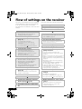
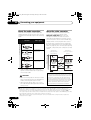
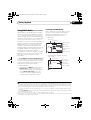
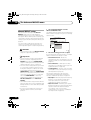
Flow of settings on the receiver
The unit is a full-fledged AV receiver equipped
with an abundance of functions and terminals.
It can be used easily after following the
procedure below to make the connections and
settings.
1
Determining the speakers’ application
(page 15)
• 7.1ch surround connection
• 5.1ch surround & Front Bi-amping
connection
• 5.1ch surround & Zone 2 connection
• 5.1ch surround & Speaker B connection
3
Connecting the speakers
• Placing the speakers (page 17)
• Connecting the speakers (page 18)
• Standard 5.1/6.1/7.1-channel surround
connections (page 19)
• Bi-amping your speakers (page 20)
4
Connecting the components
• About the audio connection (page 22)
• About the video converter (page 22)
• Connecting your TV and playback
components (page 23)
• Connecting AM/FM antennas (page 30)
• Plugging in the receiver (page 35)
5
Switching the speaker impedance
(page 36)
(Only if the impedance of the connected
speakers is 6 Ω to 8 Ω)
6
Power On
7
Changing the OSD display language
(OSD Language) (page 36)
8
Surround back speaker setting (page
94)
6
En
Required setting item
Setting to be made as necessary
Before you start
• Checking what’s in the box (page 7)
• Loading the batteries (page 7)
2
The colors of the steps indicate the following:
9
MCACC speaker settings
• Automatically setting up for surround sound
(Auto MCACC) (page 37)
10 The Input Setup menu (page 39)
(When using connections other than the
recommended connections)
11 Basic playback (page 41)
12 Adjusting the sound and picture
quality as desired
• Using the various listening modes
• Using surround back channel processing
(page 56)
• Better sound using Phase Control (page 59)
• Switches on/off the Acoustic Calibration
EQ, Sound retriever or Dialog Enhancement
(page 64)
• Change the channel level while listening
(Tip on page 97)
• Measure the all EQ type (SYMMETRY/ALL
CH ADJ/FRONT ALIGN) (page 78)
• Setting the PQLS function (page 62)
• Setting the Audio options (Tone, Loudness
or Sound delay, etc.) (page 64)
• Setting the Video options (page 67)
13 Other optional adjustments and
settings
• KURO LINK Setup (page 62)
• The Advanced MCACC menu (page 77)
• The system and the other setup (page 93)
14 Making maximum use of the remote
control
• Operating multiple receivers (page 73)
• Setting the remote to control other
components (page 73)
VSX-1019_KU.book Page 7 Thursday, January 8, 2009 12:01 PM
Before you start
01
Chapter 1:
Before you start
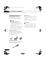
Checking what’s in the box
Loading the batteries
Please check that you’ve received the following
supplied accessories:
• Setup microphone (cable: 5 m (16.4 ft.))
• Remote control unit
• AA size IEC R6 dry cell batteries (to confirm
system operation) x2
• AM loop antenna
• FM wire antenna
• iPod cable
• These operating instructions
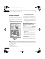
Installing the receiver
• When installing this unit, make sure to put
it on a level and stable surface.
Don’t install it on the following places:
– on a color TV (the screen may distort)
– near a cassette deck (or close to a device that
gives off a magnetic field). This may interfere
with the sound.
– in direct sunlight
– in damp or wet areas
– in extremely hot or cold areas
– in places where there is vibration or other
movement
– in places that are very dusty
– in places that have hot fumes or oils (such as
a kitchen)
• Do not touch this receiver’s bottom panel
while the power is turned on. The bottom
panel gets hot when the power is on, and
touching it could cause burns.
CAUTION
Incorrect use of batteries may result in such
hazards as leakage and bursting. Observe the
following precautions:
• Never use new and old batteries together.
• Insert the plus and minus sides of the
batteries properly according to the marks
in the battery case.
• Batteries with the same shape may have
different voltages. Do not use different
batteries together.
• When disposing of used batteries, please
comply with governmental regulations or
environmental public instruction’s rules
that apply in your country or area.
• WARNING
Do not use or store batteries in direct
sunlight or other excessively hot place,
such as inside a car or near a heater. This
can cause batteries to leak, overheat,
explode or catch fire. It can also reduce the
life or performance of batteries.
(Symbol examples for batteries)
These symbols are only valid
in the European Union.
Pb
K058c_A1_En
7
En
VSX-1019_KU.book Page 8 Thursday, January 8, 2009 12:01 PM
02
Controls and displays
Chapter 2:
Controls and displays
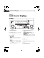
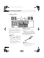
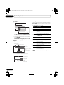
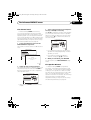
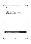
Front panel
1
2
3
4
5
6
7
8
AUDIO/VIDEO MULTI-CHANNEL RECEIVER
STANDBY/ON
ENTER
BAND
TUNE
TUNE
INPUT
SELECTOR
PHASE
CONTROL
AUTO SURR /ALC/
STREAM DIRECT
ADVANCED
MCACC
STEREO
ADVANCED
SURROUND
HDMI
STANDARD
SURROUND
SPEAKERS
USB
PRESET
PRESET
TUNER EDIT
MULTI-ZONE
CONTROL
ON / OFF
iPod
iPhone
VIDEO
VIDEO INPUT
L AUDIO
MASTER
VOLUME
R
MCACC
SETUP MIC
PHONES
9
10
1 INPUT SELECTOR dial
Use to select an input function.
11 12
4
2 STANDBY/ON
Switches the receiver between on and standby.
Power indicator lights when the receiver is on.
8
En
Tuner controls
BAND – Switches between AM and FM
radio bands (page 51).
TUNE +/– – Use to find radio frequencies
(page 51).
PRESET +/– – Use to find preset stations
(page 52).
TUNER EDIT – Use with TUNE +/–, PRESET
+/– and ENTER to memorize and name
stations for recall (page 52).
14
PHASE CONTROL indicator – Lights to
indicate Phase Control is selected
(page 59).
ADVANCED MCACC indicator – Lights
when EQ is set to ON in the AUDIO
PARAMETER menu.
When the KURO LINK function is set to ON,
the power indicator lights dimly when the
power is in standby.
3
13
HDMI indicator – Blinks when connecting
an HDMI-equipped component; lights when
the component is connected (page 23).
5 Character display
See Display on page 9.
6
ENTER
7 Remote sensor
Receives the signals from the remote control
(see Operating range of remote control unit on
page 13).
8
MASTER VOLUME dial
VSX-1019_KU.book Page 9 Thursday, January 8, 2009 12:01 PM
Controls and displays
02
9 PHONES jack
Use to connect headphones. When the
headphones are connected, there is no sound
output from the speakers.
11 SPEAKERS
Use to change the speaker system (page 69).
12 MULTI-ZONE controls
If you’ve made MULTI-ZONE connections (see
MULTI-ZONE setup on page 31) use these
controls to control the sub zone from the main
zone (see Using the MULTI-ZONE controls on
page 69).
10 Listening mode buttons
AUTO SURR/ALC/STREAM DIRECT –
Switches between Auto Surround (page 53),
Auto level control mode and Stream Direct
mode (page 56).
STEREO – Switches between stereo
playback, and Front Stage Surround
Advance modes (page 55).
ADVANCED SURROUND – Use to switch
between the various surround modes
(page 54).
STANDARD SURROUND – Press for
Standard decoding and to switch between
the various 2 Pro Logic IIx and Neo:6
options (page 53).
13 iPod/iPhone/USB, VIDEO INPUT
terminals
Use to connect your Apple iPod as an audio
and video source, or connect a USB device for
audio and photo playback (page 34, 35).
See Connecting a component to the front panel
inputs on page 34.
14 MCACC SETUP MIC jack
Use to connect the supplied microphone
(page 37).
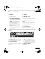
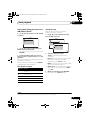
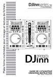
Display
1
AUTO
PCM
HDMI
DIGITAL
ANALOG
2
L
SL
XL
C
XC
LFE
3
45
R 2DIGITAL PLUS
2TrueHD WMA9Pro
SR DTS HD ES 96/24
XR
MSTR
AUTO SURROUND
STREAM DIRECT
CD
CD-R
TUNER
6
7 8
9 10 11 12
13
14
15
DSD PCM
TUNED
MULTI-ZONE PQLS ALC ATT STEREO
S.RTRV SOUND UP MIX OVER MONO
SIRIUS
iPod
DVD TV
BD DVR
VIDEO
HDMI
16 17
dB
USB
[2] [3] [4]
2PROLOGIC x Neo:6
ADV.SURROUND
STEREO STANDARD
SP AB
SLEEP
10
18
19 20 21
1 SIGNAL indicators
Light to indicate the currently selected input
signal. AUTO lights when the receiver is set to
select the input signal automatically (page 58).
2 Program format indicators
Light to indicate the channels being input
when PCM signals are being input. They do not
indicate the audio signals being output from
the receiver.
22
23
L/R – Left front/Right front channel
C – Center channel
SL/SR – Left surround/Right surround channel
LFE – Low frequency effects channel (the (( ))
indicators light when an LFE signal is being input)
XL/XR – Two channels other than the ones above
XC – Either one channel other than the ones above,
the mono surround channel or matrix encode flag
3 Digital format indicators
Light when a signal encoded in the corresponding
format is detected.
9
En
VSX-1019_KU.book Page 10 Thursday, January 8, 2009 12:01 PM
02
Controls and displays
4 S.RTRV
Lights when the Sound Retriever function is
active (page 65).
5 MULTI-ZONE
Lights when the MULTI-ZONE feature is active
(page 69).
6
DSD PCM – Light during DSD (Direct Stream
Digital) to PCM conversion with SACDs.
PCM – Lights during playback of PCM
signals.
7 SOUND
Lights when any of the Midnight, Loudness or
tone controls feature is selected (page 64).
Lights when Dialog Enhancement is switched on.
8 PQLS
Lights when the PQLS feature is active (page 62).
9 UP MIX
Lights when the UP Mix is switched on (page 57).
10 Listening mode indicators
AUTO SURROUND – Lights when the Auto
Surround feature is switched on (page 53).
ALC – Lights when the ALC (Auto level
control) mode is selected (page 56).
STREAM DIRECT – Lights when Direct/
Pure Direct is selected (page 56).
ADV.SURROUND – Lights when one of the
Advanced Surround modes has been
selected (page 54).
STEREO – Lights when stereo listening is
switched on (page 55).
STANDARD – Lights when one of the
Standard Surround modes is switched on
(page 53).
11
(PHASE CONTROL)
Lights when the Phase Control is switched on
(page 59).
12 Analog signal indicators
Light to indicate reducing the level of an analog
signal (page 71).
10
En
13 Tuner indicators
TUNED – Lights when a broadcast is being
received.
STEREO – Lights when a stereo FM broadcast
is being received in auto stereo mode.
MONO – Lights when the mono mode is set
using MPX.
14
Lights when the sound is muted (page 13).
15 Master volume level
Shows the overall volume level.
“---” indicates the minimum level, and “+12dB”
indicates the maximum level.
16 Input function indicators
Light to indicate the input function you have
selected.
17 Scroll indicators
Light when there are more selectable items
when making the various settings.
18 Matrix decoding format indicators
2PRO LOGIC IIx – This lights to indicate
2 Pro Logic II / 2 Pro Logic IIx decoding
(page 53).
Neo:6 – When one of the Neo:6 modes of the
receiver is on, this lights to indicate Neo:6
processing (page 53).
19 Speaker indicators
Lights to indicate the current speaker system,
A and/or B (page 69).
20 SLEEP
Lights when the receiver is in sleep mode (page 71).
21 MSTR
Lights during playback of DTS-HD Master
Audio signal.
22 Character display
Displays various system information.
23 Remote control mode indicator
Lights to indicate the receiver’s remote control
mode setting. (Not displayed when set to 1.)
(page 73)
VSX-1019_KU.book Page 11 Thursday, January 8, 2009 12:01 PM
Controls and displays
02
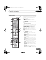
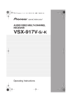
Remote control
12
RECEIVER
SOURCE
1
2
13
DVD
BD
TV
CD
iPod USB TUNER
DVR
HDMI
CD-R
VIDEO
1 RECEIVER
This switches between standby and on for this
receiver.
INPUT
SELECT
3
2
3
SIGNAL SEL
MCACC
SLEEP
4
5
6
SBch
A.ATT
DIMMER
7
8
D.ACCESS
CH LEVEL
CLASS
0
ENTER
INPUT
MASTER
VOLUME
CH
VOL
6
14
3 Number buttons and other receiver/
component controls
Use the number buttons to directly select a
radio frequency (page 51) or the tracks on a
CD, DVD, etc.
15
ENTER can be used to enter commands for TV
or DTV.
MUTE
AUDIO
PARAMETER
VIDEO
PARAMETER
TUNE
LIST
5
2 Input function buttons
Press to select control of other components (see
Controlling the rest of your system on page 73).
9
TV CONTROL
4
Press RECEIVER first to access:
INPUT SELECT – Use to select the input
function (page 41).
TOOLS
TOP MENU
BAND
T.EDIT
GUIDE
ENTER
PRESET
PRESET
CATEGORY
SIGNAL SEL – Use to select an input signal
(page 58).
RETURN
HOME
MENU
MCACC – Press to switch between MCACC
presets (page 58).
TUNE
iPod CTRL
7
DVD
PHASE CTRL
8
9
ANT
MPX
AUDIO
INFO
STATUS
PQLS
11
SBch – Use to select the surround back/virtual
surround back channel mode (page 56).
MEMORY
CH
DISP
TV CTRL RECEIVER
10
SLEEP – Use to put the receiver in sleep
mode and select the amount of time before
sleep (page 71).
AUTO/ALC/
MENU
DIRECT STEREO STANDARD ADV SURR
HDD
REMOTE
SETUP
MAIN
• White – Receiver control, TV Control
• Blue – Other controls
SIRIUS
1
The remote has been conveniently color-coded
according to component control using the
following system:
ZONE 2
RECEIVER
16
A.ATT – Attenuates (lowers) the level of an
analog input signal to prevent distortion
(page 71).
DIMMER – Dims or brightens the display
(page 71).
CH LEVEL – Press repeatedly to select a
channel, then use / to adjust the level
(page 97).
11
En
VSX-1019_KU.book Page 12 Thursday, January 8, 2009 12:01 PM
02
Controls and displays
Press TUNER first to access:
D.ACCESS – After pressing, you can
access a radio station directly using the
number buttons (page 51).
CLASS – Switches between the seven
banks (classes) of radio station presets
(page 52).
4 TV CONTROL buttons
These buttons are dedicated to control the TV
assigned to TV operation selector switch. Thus
if you only have one TV to hook up to this
system assign it to the TV operation selector
switch (see page 75 for more on this).
– Use to turn on/off the power of the TV.
INPUT – Use to select the TV input signal.
CH +/– – Use to select channels.
VOL +/– – Use to adjust the volume on your
TV.
5 Tuner/component control buttons/HOME
MENU
These button controls can be accessed after
you have selected the corresponding input
function button (DVD, DVR, TV, etc.). The
BAND and T.EDIT tuner controls are explained
on page 51 and page 52.
Press RECEIVER first to access:
AUDIO PARAMETER – Use to access the
Audio options (page 64).
VIDEO PARAMETER – Use to access the
Video options (page 67).
HOME MENU – Use to access the Home
Menu (pages 36, 39, 62, 77, 93 and 98).
RETURN – Press to confirm and exit the
current menu screen (also use to return to
the previous menu with DVDs or to select
closed captioning with DTV).
12
En
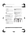
6 /// (TUNE/PRESET) /ENTER
Use the arrow buttons when setting up your
surround sound system (see page 77) and the
Audio or Video options (page 64 or 67). Also
used to control DVD menus/options and for
deck 1 of a double cassette deck player. Use
TUNE/ to find radio frequencies and use
PRESET / to find preset stations (page 52).
7 Receiver controls
Press RECEIVER first to access:
AUTO/ALC/DIRECT – Switches between
Auto Surround (page 53), Auto level control
mode and Stream Direct mode (page 56).
STEREO – Switches between stereo
playback, and Front Stage Surround
Advance modes (page 55).
STANDARD – Press for Standard decoding
and to switch between the various 2 Pro
Logic IIx and Neo:6 options (page 53).
ADV SURR – Use to switch between the
various surround modes (page 54).
8 Component control buttons
The main buttons (, , etc.) are used to
control a component after you have selected it
using the input function buttons.
The controls above these buttons can be
accessed after you have selected the
corresponding input function button (for
example DVD, DVR or TV). These buttons also
function as described below.
Press TV first to access:
ANT – Use to select the VHF/UHF antennas
or Cable TV.
Press TUNER first to access:
MPX – Switches between stereo and mono
reception of FM broadcasts. If the signal is
weak, then switching to mono will improve
the sound quality (page 51).
VSX-1019_KU.book Page 13 Thursday, January 8, 2009 12:01 PM
Controls and displays
Press RECEIVER first to access:
PHASE CTRL – Press to switch on/off
Phase Control (page 59).
9
02
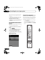
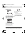
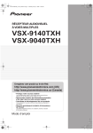
Operating range of remote control
unit
The remote control may not work properly if:
STATUS – Press to check selected receiver
settings (page 71).
• There are obstacles between the remote
control and the receiver’s remote sensor.
AUDIO – Changes the audio or channel on
DVD discs.
DISPLAY – Switches between named
station presets and radio frequencies.
• Direct sunlight or fluorescent light is
shining onto the remote sensor.
CH +/– – Use to select channels for DVD/
DVR units.
• The receiver is operated simultaneously
with another infrared remote control unit.
10 REMOTE SETUP – Use to input the preset
code when making remote control settings
and to set the remote control mode
(page 73).
TV CTRL – Use this button to set preset
code of your TV’s manufacturer when
controlling TV (see Selecting preset codes
directly on page 73 for more on this).
11 MULTI-ZONE operation selector switch
Switch to perform operations in the main zone
and sub zone (page 70).
• The receiver is located near a device that is
emitting infrared rays.
30°
30°
7 m (23 ft.)
12 Remote control LED
Lights when a command is sent from the
remote control (page 73).
13 SOURCE
Press to turn on/off other components
connected to the receiver (see page 73 for
more on this).
14 MASTER VOLUME +/–
Use to set the listening volume.
15 MUTE
Mutes the sound or restores the sound if it has
been muted (adjusting the volume also
restores the sound).
16 RECEIVER
Switches the remote to control the receiver
(used to select the white commands above the
number buttons (A.ATT, etc.)). Also use this
button to set up surround sound.
13
En
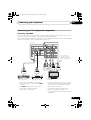
VSX-1019_KU.book Page 14 Thursday, January 8, 2009 12:01 PM
03
Connecting your equipment
Chapter 3:
Connecting your equipment
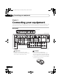
This receiver provides you with many connection possibilities, but it doesn’t have to be difficult. This
page explains the kinds of components you can connect to make up your home theater system.
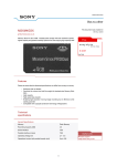
Rear panel
VSX-919AH
DIGITAL
AUDIO
COAXIAL
HDMI
ASSIGNABLE
1 2
ASSIGNABLE
IN 1
BD IN
AUDIO
Y
IN 2
IN (DVD)
OUT
VSX-1019AH
FRONT
L
HDMI DIGITAL
AUDIO
1 3
COAXIAL
ASSIGNABLE
IN 1
BD IN
ASSIGNABLE
IN 3
ASSIGNABLE
IN 1 (DVD) IN 2 (CD)
FRONT
OUT
Y
PB
PB R
PR
IN 1
(DVD)
PR
IN 2
(DVR)
OPTICAL
SIRIUS IN
ASSIGNABLE
IN 1 (TV/SAT)
IN 2 (DVR)
CENTER SURROUND
AM
LOOP
PRE OUT
L
Y
Y
IN 2
AUDIO
FM
UNBAL
75
ZONE2
OUT
DVD
IN
TV/SAT
IN
OUT
DVR
AUX
IN
IN
CD
IN
OUT
CD-R
R
SUBWOOFER
MONITOR
OUT
SUBWOOFER
MULTI CH IN
IN
SPEAKERS FRONT
A
L
CENTER
R
SURROUND
ANTENNA
L
R SURROUND BACK / B L
(Single)
IN
IR
VIDEO
PB
OUT
IN
CONTROL
PR
OUT
COMPONENT
VIDEO
Important
• Illustration shows the VSX-1019AH,
however connections for the VSX-919AH
are the same except where noted.
CAUTION
• Before making or changing the
connections, switch off the power and
disconnect the power cord from the power
outlet. Plugging in should be the final step.
• To avoid hum, do not lay connected cables
over the top of the receiver.
14
En
VSX-1019_KU.book Page 15 Thursday, January 8, 2009 12:01 PM
Connecting your equipment
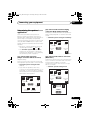
Determining the speakers’
application
Surround sound with a strong sense of
presence can be enjoyed by connecting 7
speakers and 1 subwoofer. It is also possible to
achieve high sound quality using bi-amp
connections and to enjoy music in other rooms
using the MULTI-ZONE feature. High sound
quality can be achieved with a minimum of two
speakers.
• Be sure to connect speakers to the front
left and right channels ( FL and FR ).
• The Surr Back System setting must be
made if you use any of the connections
shown below other than [1] (see Selecting
the Surr Back system on page 21).
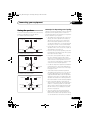
03
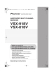
[2] 5.1ch surround & Front Bi-amping
connection (High quality surround)
Bi-amping connection of the front speakers for
high sound quality with 5.1-channel surround
sound.
• Surr Back System setting: Front Bi-Amp
FL
FR
SW
C
Front
left*
Front
right*
Center
Subwoofer
Surround
right
Surround
left
SR
SL
*Bi-amp compatible speaker
[1] 7.1ch surround connection
(Simple connection & Best surround)
[3] 5.1ch surround & Zone 2 connection
(Multi Zone)
*Default setting
With these connections you can simultaneously
enjoy 5.1-channel surround sound in the main
zone with stereo playback on another
component in Zone 2. (The selection of input
devices is limited.)
These connections prioritize surround sound
with a speaker layout like that in a movie theater.
• Surr Back System setting: Normal
(default)
• If you have six speakers, either only
connect one surround back speaker (6.1 ch
surround), or connect for the 7.1-channel
setting as shown on the diagram below but
without the center speaker.
• Surr Back System setting: Zone2
FL
FR
SW
C
Front
left
Front
right
Center
Subwoofer
FL
FR
SW
C
Front
left
Front
right
Center
Subwoofer
Surround
right
Surround
left
SR
SL
SR
SL
Surround
left
Surround
right
SBL
Surround
back left
SBR
Surround
back right
L
R
Left
Right
ZONE2
15
En
VSX-1019_KU.book Page 16 Thursday, January 8, 2009 12:01 PM
03
Connecting your equipment
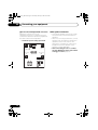
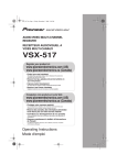
[4] 5.1ch surround & Speaker B connection
With these connections you can
simultaneously enjoy 5.1-channel surround
sound in the main zone with stereo playback of
the same sound on the B speakers.
• Surr Back System setting: Speaker B
FL
FR
SW
Front
left
C
Center
Front
right
Subwoofer
Surround
left
SL
Surround
right
SR
Speaker B
16
En
Other speaker connection
• Your favorite speaker connections can be
selected even if you have fewer than 5.1
speakers.
• When not connecting a subwoofer, connect
speakers with low frequency reproduction
capabilities to the front channel. (The
subwoofer’s low frequency component is
played from the front speakers, so the
speakers could be damaged.)
• After connecting, be sure to conduct
the Auto MCACC (speaker environment
setting) procedure (page 37).
VSX-1019_KU.book Page 17 Thursday, January 8, 2009 12:01 PM
Connecting your equipment
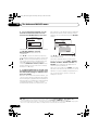
Some tips for improving sound quality
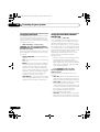
Placing the speakers
To achieve the best possible surround sound,
install your speakers as shown below.
5.1 channel surround system:
Center
Front right
Front left
Subwoofer
120°
120°
Surround
right
Surround
left
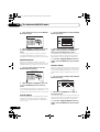
6.1 channel surround system:
Center
Front left
Front right
Subwoofer
120°
120°
Surround
left
Surround
right
Surround Back
7.1 channel surround system:
Center
Front right
Front left
Subwoofer
90°
90°
Surround
left
Surround back
left
Surround
right
60°
03
Surround back
right
Where you put your speakers in the room has a
big effect on the quality of the sound. The
following guidelines should help you to get the
best sound from your system.
• The subwoofer can be placed on the floor.
Ideally, the other speakers should be at
about ear-level when you’re listening to
them. Putting the speakers on the floor
(except the subwoofer), or mounting them
very high on a wall is not recommended.
• For the best stereo effect, place the front
speakers 2 m to 3 m (6 ft. to 9 ft.) apart, at
equal distance from the TV.
• If you’re using a center speaker, place the
front speakers at a wider angle. If not, place
them at a narrower angle.
• Place the center speaker above or below
the TV so that the sound of the center
channel is localized at the TV screen. Also,
make sure the center speaker does not
cross the line formed by the leading edge
of the front left and right speakers.
• It is best to angle the speakers towards the
listening position. The angle depends on
the size of the room. Use less of an angle
for bigger rooms.
• Surround and surround back speakers
should be positioned 60 cm to 90 cm (2 ft.
to 3 ft.) higher than your ears and tilted
slight downward. Make sure the speakers
don’t face each other. For DVD-Audio, the
speakers should be more directly behind
the listener than for home theater playback.
• If the surround speakers cannot be set
directly to the side of the listening position
with a 7.1-channel system, the surround
effect can be enhanced by turning off the
UP Mix function (see Setting the Up Mix
function on page 57).
• Try not to place the surround speakers
farther away from the listening position
than the front and center speakers. Doing
so can weaken the surround sound effect.
17
En
VSX-1019_KU.book Page 18 Thursday, January 8, 2009 12:01 PM
03
Connecting your equipment
Connecting the speakers
Each speaker connection on the receiver
comprises a positive (+) and negative (–)
terminal. Make sure to match these up with the
terminals on the speakers themselves.
• Use an RCA cable to connect the subwoofer.
It is not possible to connect using speaker
cables.
CAUTION
• These speaker terminals carry
HAZARDOUS LIVE voltage. To prevent
the risk of electric shock when connecting
or disconnecting the speaker cables,
disconnect the power cord before touching
any uninsulated parts.
• Make sure that all the bare speaker wire is
twisted together and inserted fully into the
speaker terminal. If any of the bare speaker
wire touches the back panel it may cause
the power to cut off as a safety measure.
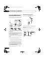
Bare wire connections
1 Twist exposed wire strands together.
(fig. A)
2 Loosen terminal and insert exposed wire.
(fig. B)
3
Tighten terminal. (fig. C)
fig. A
fig. B
fig. C
10 mm (3/8 in.)
Banana plug connections
If you want to use speaker cables terminated
with banana plugs, screw the speaker terminal
fully shut, then plug the banana plug into the
end of the speaker terminal.
18
En
Important
• Please refer to the manual that came with
your speakers for details on how to connect
the other end of the speaker cables to your
speakers.
CAUTION
• Make sure that all speakers are securely
installed. This not only improves sound
quality, but also reduces the risk of
damage or injury resulting from speakers
being knocked over or falling in the event of
external shocks such as earthquakes.
VSX-1019_KU.book Page 19 Thursday, January 8, 2009 12:01 PM
Connecting your equipment
03
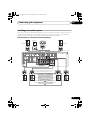
Installing your speaker system
At the very least, front left and right speakers only are necessary. Note that your main surround
speakers should always be connected as a pair, but you can connect just one surround back
speaker if you like (it must be connected to the left surround back terminal).
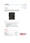
Standard 5.1/6.1/7.1-channel surround connections
Center
Subwoofer
Front right
Front left
LINE LEVEL
INPUT
VSX-1019AH
HDMI DIGITAL
AUDIO
1 3
COAXIAL
ASSIGNABLE
IN 1
BD IN
ASSIGNABLE
IN 3
ASSIGNABLE
IN 1 (DVD) IN 2 (CD)
FRONT
OUT
AUDIO
Y
PB
PB R
PR
IN 1
(DVD)
PR
IN 2
(DVR)
OPTICAL
SIRIUS IN
ASSIGNABLE
IN 1 (TV/SAT)
IN 2 (DVR)
CENTER SURROUND
AM
LOOP
PRE OUT
L
Y
Y
IN 2
FM
UNBAL
75
ZONE2
OUT
DVD
IN
TV/SAT
IN
OUT
DVR
AUX
IN
IN
CD
IN
OUT
CD-R
SUBWOOFER
R
MULTI CH IN
IN
SPEAKERS FRONT
A
MONITOR
OUT
L
CENTER
R
SUBWOOFER
SURROUND
ANTENNA
L
R SURROUND BACK / B L
(Single)
IN
IR
PB
VIDEO
OUT
IN
PR
CONTROL
OUT
COMPONENT
VIDEO
The surround back terminals can also be
used for the Speaker B and Zone 2.
7.1 ch surround setting
Surround back right
Surround back left
Surround left
6.1 ch surround setting
Surround back
No connect
Speaker B setting
Speaker B - Left
Speaker B - Right
Zone 2 setting
Zone 2 - Left
Zone 2 - Right
Surround right
19
En
VSX-1019_KU.book Page 20 Thursday, January 8, 2009 12:01 PM
03
Connecting your equipment
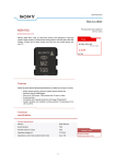
Bi-amping your speakers
Bi-amp compatible
speaker
Bi-amp compatible
speaker
Center
Subwoofer
High
High
Low
Low
Front right
Front left
HDMI DIGITAL
AUDIO
1 3
COAXIAL
OPTICAL
ASSIGNABLE
IN 1
BD IN
ASSIGNABLE
IN 3
Y
PB R
PR
IN 2
(DVR)
MONITOR
OUT
PB
VIDEO
SIRIUS IN
IN 1 (TV/SAT)
IN 2 (DVR)
CENTER SURROUND
AM
LOOP
PRE OUT
L
Y
PR
IN 1
(DVD)
ASSIGNABLE
ASSIGNABLE
IN 1 (DVD) IN 2 (CD)
FRONT
OUT
AUDIO
PB
Y
IN 2
FM
UNBAL
75
ZONE2
OUT
DVD
IN
TV/SAT
IN
OUT
DVR
AUX
IN
IN
CD
IN
OUT
CD-R
SUBWOOFER
MULTI CH IN
IN
SPEAKERS FRONT
A
R
L
CENTER
R
SUBWOOFER
SURROUND
ANTENNA
L
R SURROUND BACK / B L
(Single)
IR
IN
OUT
IN
PR
CONTROL
OUT
COMPONENT
VIDEO
Surround right
Bi-amping is when you connect the high
frequency driver and low frequency driver of
your speakers to different amplifiers for better
crossover performance. Your speakers must be
bi-ampable to do this (having separate
terminals for high and low) and the sound
improvement will depend on the kind of
speakers you’re using.
CAUTION
Surround left
VSX-1019AH
Bi-wiring your speakers
Your speakers can also be bi-wired if they
support bi-amping.
• With these connections, the Surr Back
System setting makes no difference.
• To bi-wire a speaker, connect two speaker
cables to the speaker terminal on the receiver.
Using a banana plug for the second
connection is recommended.
• Most speakers with both High and Low
terminals have two metal plates that
connect the High to the Low terminals.
These must be removed when you are biamping the speakers or you could severely
damage the amplifier. See your speaker
manual for more information.
• If your speakers have a removable
crossover network, make sure you do not
remove it for bi-amping. Doing so may
damage your speakers.
CAUTION
• Don’t connect different speakers from the
same terminal in this way.
• When bi-wiring as well, heed the cautions
for bi-amping shown at the left.
20
En
VSX-1019_KU.book Page 21 Thursday, January 8, 2009 12:01 PM
Connecting your equipment
Selecting the Surr Back system
The surround back terminals can be used for
bi-amping, Speaker B and Zone 2 connections,
in addition to for the surround back speakers.
Make this setting according to the application.
03
2 Select the ‘Front Bi-Amp’ setting from
the ‘Surr Back System’ menu.
See Surround back speaker setting on page 94
to do this.
Zone 2 setup
With these connections you can
simultaneously enjoy 5.1-channel surround
sound in the main zone with stereo playback
on another component in Zone 2.
1 Connect a pair of speakers to the surround
back speaker terminals.
See Standard 5.1/6.1/7.1-channel surround
connections on page 19.
2 Select ‘ZONE 2’ from the Surr Back
System menu.
See Surround back speaker setting on page 94
to do this.
Speaker B setup
You can listen to stereo playback in another
room.
1 Connect a pair of speakers to the surround
back speaker terminals.
See Standard 5.1/6.1/7.1-channel surround
connections on page 19.
2 Select ‘Speaker B’ from the Surr Back
System menu.
See Surround back speaker setting on page 94
to do this.
Bi-Amping setup
Bi-amping connection of the front speakers for
high sound quality with 5.1-channel surround
sound.
1 Connect a Bi-amp compatible speakers to
the front and surround back speaker
terminals.
See Bi-amping your speakers on page 20.
21
En
VSX-1019_KU.book Page 22 Thursday, January 8, 2009 12:01 PM
03
Connecting your equipment
About the audio connection
About the video converter
There are several types of audio input and
output terminals on this receiver. The receiver
selects the first available signal in the following
order:
The video converter ensures that all video
sources are output through all of the
MONITOR VIDEO OUT jacks. The only
exception is HDMI: since this resolution
cannot be downsampled, you must connect
your monitor/TV to the receiver’s HDMI video
outputs when connecting this video source.1
HDMI
Digital (Coaxial)
Transferable
audio signals
HD audio
If several video components are assigned to
the same input function (see The Input Setup
menu on page 39), the converter gives priority
to HDMI, component, then composite (in that
order).
Conventional
digital audio
Terminal for
connection with
source device
Terminal for
connection with TV
monitor
Digital (Optical)
RCA (Analog)
(White/Red)
Conventional
analog audio
• With an HDMI cable, video and audio
signals can be transferred in high quality
over a single cable.
CAUTION
• When connecting optical cables, be careful
when inserting the plug not to damage the
shutter protecting the optical socket.
• When storing optical cable, coil loosely.
The cable may be damaged if bent around
sharp corners.
High picture quality
Sound signal priority
Types of cables and
terminals
HDMI OUT
HDMI IN
PB
PR
Y
PB
PR
Y
COMPONENT
VIDEO IN
COMPONENT VIDEO
MONITOR OUT
VIDEO IN
VIDEO
MONITOR OUT
Video signals can be output
This product incorporates copyright protection
technology that is protected by method claims of certain
U.S. patents and other intellectual property rights owned
by Macrovision Corporation and other rights owners.
Use of this copyright protection technology must be
authorized by Macrovision Corporation, and is intended
for home and other limited viewing uses only unless
otherwise authorized by Macrovision Corporation.
Reverse engineering or disassembly is prohibited.
Note
1 • If the video signal does not appear on your TV or flat panel TV, try adjusting the resolution settings on your
component or display. Note that some components (such as video game units) have resolutions that may not be
converted. In this case, try switching Digital Video Conversion (in Setting the Video options on page 67) OFF.
• The signal input resolutions that can be converted from the component video input for the HDMI output are 480i/
576i, 480p/576p, 720p and 1080i. 1080p signals cannot be converted.
• Only signals with an input resolution of 480i/576i can be converted from the component video input for the
composite monitor output.
22
En
VSX-1019_KU.book Page 23 Thursday, January 8, 2009 12:01 PM
Connecting your equipment
03
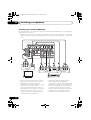
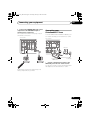
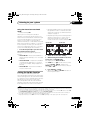
Connecting your TV and playback components
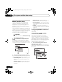
Connecting using HDMI
If you have an HDMI or DVI (with HDCP) equipped component (Blu-ray disc player, etc.), you can
connect it to this receiver using a commercially available HDMI cable.
If the TV and playback components support the Pioneer KURO LINK feature, the convenient KURO
LINK functions can be used (see KURO LINK on page 60).
VSX-1019AH
HDMI
DIGITAL
ASSIGNABLE AUDIO
OPTICAL
1 3 COAXIAL
ASSIGNABLE
BD IN
ASSIGNABLE
IN 1
ASSIGNABLE
IN 2 (DVR)
IN 1 (DVD) IN 2 (CD) IN 1 (TV/SAT)
OUT
IN 3
FRONT
Y
Y
PB R
PR
IN 1
(DVD)
PR
IN 2
(DVR)
CENTER SURROUND
PRE OUT
L
PB
Y
IN 2
AUDIO
ZONE2
OUT
DVD
IN
TV/SAT
IN
OUT
DVR
AUX
IN
IN
CD
IN
OUT
CD-R
R
SUBWOOFER
SUBWOOFER
MULTI CH IN
IN
SPEAKERS FRONT
A
MONITOR
OUT
L
CENTER
R
SURROUND
L
IN
IR
OUT
VIDEO
PB
IN
CONTROL
PR
This connection is
required in order to
listen to the sound of
the TV over the receiver.
OUT
COMPONENT
VIDEO
R ANALOG L
AUDIO OUT
COAXIAL OPTICAL
DIGITAL OUT
Select one
HDMI OUT
HDMI/DVI-compatible
Blu-ray disc player
HDMI IN
HDMI OUT
Other HDMI/DVIequipped component
• When connecting a Blu-ray disc player,
connect the player to the receiver’s BD IN
terminal.
• The HDMI indicator lights on the front
panel when an HDMI-equipped
component is connected.
HDMI/DVI-compatible monitor
or flat panel TV
• For input components, connections other
than HDMI connections are also possible
(see Connecting your DVD player with no
HDMI output on page 25).
• If your Blu-ray disc player offers multichannel analog audio outputs, see
Connecting the multichannel analog inputs
on page 28.
23
En
VSX-1019_KU.book Page 24 Thursday, January 8, 2009 12:01 PM
03
Connecting your equipment
• The sound of the TV cannot be heard over
the receiver if the TV is connected using an
HDMI cable.
If you want to listen to the sound of the TV
over the receiver, connect the receiver and
TV with audio cables.
About HDMI1
The HDMI connection transfers
uncompressed digital video, as well as almost
every kind of digital audio that the connected
component is compatible with, including DVDVideo, DVD-Audio, SACD, Dolby Digital Plus,
Dolby TrueHD, DTS-HD Master Audio (see
below for limitations), Video CD/Super VCD
and CD. See About the video converter on
page 22 for more on HDMI compatibility.
• Synchronized operation with components
using the KURO LINK function (see KURO
LINK on page 60)
HDMI, the HDMI logo and High-Definition
Multimedia Interface are trademarks or
registered trademarks of HDMI Licensing, LLC.
“x.v.Color” and x.v.Color logo are trademarks of
Sony Corporation.
This receiver incorporates High-Definition
Multimedia Interface (HDMI™) technology.
This receiver supports the functions described
below through HDMI connections.
• Digital transfer of uncompressed video
(contents protected by HDCP (1080p/24,
1080p/60, etc.))
• DeepColor signal transfer2
• x.v.Color signal transfer2
• Input of multi-channel linear PCM digital
audio signals (192 kHz or less) for up to 8
channels
• Input of the following digital audio formats:
– Dolby Digital, Dolby Digital Plus, DTS,
High bitrate audio (Dolby TrueHD, DTS-HD
Master Audio), DVD-Audio, CD, SACD
(DSD signal), Video CD, Super VCD
Note
1 • An HDMI connection can only be made with DVI-equipped components compatible with both DVI and High
Bandwidth Digital Content Protection (HDCP). If you choose to connect to a DVI connector, you will need a separate
adaptor (DVIHDMI) to do so. A DVI connection, however, does not support audio signals. Consult your local audio
dealer for more information.
• If you connect a component that is not compatible with HDCP, an HDCP ERROR message is displayed on the front
panel display. Some components that are compatible with HDCP still cause this message to be displayed, but so long
as there is no problem with displaying video this is not a malfunction.
• Depending on the component you have connected, using a DVI connection may result in unreliable signal transfers.
• This receiver supports SACD, Dolby Digital Plus, Dolby TrueHD and DTS-HD Master Audio. To take advantage of these
formats, however, make sure that the component connected to this receiver also supports the corresponding format.
2 Signal transfer is only possible when connected to a compatible component.
24
En
VSX-1019_KU.book Page 25 Thursday, January 8, 2009 12:01 PM
Connecting your equipment
03
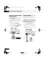
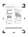
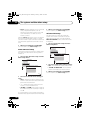
Connecting your DVD player with no HDMI output
This diagram shows connections of a TV (with HDMI input) and DVD player (or other playback
component with no HDMI output) to the receiver.
VSX-1019AH
HDMI
DIGITAL
ASSIGNABLE AUDIO
1 3 COAXIAL
OPTICAL
ASSIGNABLE
IN 1
BD IN
ASSIGNABLE
IN 2
IN 1 (DVD) IN 2 (CD)
OUT
IN 3
FRONT
AUDIO
Y
Y
ASSIGNABLE
IN 1 (TV/SAT)
IN 2
CENTER SURROUND
(DVR)
PRE OUT
L
PB R
PB
PR
IN 1
(DVD)
PR
IN 2
(DVR)
ZONE2
OUT
DVD
IN
TV/SAT
IN
OUT
DVR
AUX
IN
IN
Y
CD
IN
OUT
CD-R
SPEAKERS
A R
MONITOR
OUT
SUBWOOFER
MULTI CH IN
IN
FRONT
L
CENTER
R
SUBWOOFER
SURROUND
L
IN
IR
OUT
VIDEO
PB
IN
CONTROL
PR
OUT
COMPONENT
VIDEO
HDMI IN
PR
PB
Y
COMPONENT VIDEO OUT
R ANALOG L
VIDEO OUT
Select one
AUDIO OUT
COAXIAL
OPTICAL
DIGITAL OUT
Select one
DVD player etc.
HDMI/DVI-compatible monitor
or flat panel TV
• If you want to listen to the sound of the TV
over the receiver, connect the receiver and
TV with audio cables.
• Component video should give superior
picture quality when compared to
composite. You can also take advantage of
progressive scan video (if your source and
TV are both compatible), which delivers a
very stable, flicker-free picture. See the
manuals that came with your TV and
source component to check whether they
are compatible with progressive-scan
video.
25
En
VSX-1019_KU.book Page 26 Thursday, January 8, 2009 12:01 PM
03
Connecting your equipment
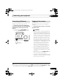
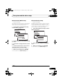
Connecting your TV with no HDMI input
This diagram shows connections of a TV (with no HDMI input) and DVD player (or other playback
component) to the receiver.
• With these connections, the picture is not output to the TV even if the DVD player is connected
with an HDMI cable. Connect the DVD player’s video signals using a composite or component
cord.
VSX-1019AH
HDMI
DIGITAL
ASSIGNABLE AUDIO
1 3 COAXIAL
OPTICAL
ASSIGNABLE
IN 3
IN 1 (DVD) IN 2 (CD)
OUT
FRONT
AUDIO
Y
Y
PB
ASSIGNABLE
IN 1 (TV/SAT)
IN
CENTER SURROUND
2 (DVR)
PRE OUT
L
PB R
PR
IN 1
(DVD)
Y
IN 2
IN 1
BD IN
ASSIGNABLE
PR
IN 2
(DVR)
ZONE2
OUT
DVD
IN
TV/SAT
IN
DVR
OUT
AUX
IN
IN
CD
IN
OUT
CD-R
R
SUBWOOFER
MULTI CH IN
IN
SPEAKERS FRONT
A
MONITOR
OUT
L
CENTER
R
SUBWOOFER
SURROUND
L
IN
IR
PB
VIDEO
OUT
IN
CONTROL
PR
OUT
COMPONENT
VIDEO
PB
PR
Y
COMPONENT VIDEO IN
VIDEO IN
Select one
R ANALOG L
AUDIO OUT
COAXIAL
OPTICAL
DIGITAL OUT
PR
HDMI OUT
Select one
TV
• Connect using an HDMI cable to listen to
HD audio on the receiver. Do not use an
HDMI cable to input video signals.
Depending on the video component, it may
not be possible to output signals
connected by HDMI and other methods
simultaneously, and it may be necessary to
make output settings. Please refer to the
operating instructions supplied with your
component for more information.
26
En
VIDEO OUT
PB
Y
COMPONENT VIDEO OUT
Select one
DVD player etc.
• Component video should give superior
picture quality when compared to
composite. You can also take advantage of
progressive scan video (if your source and
TV are both compatible), which delivers a
very stable, flicker-free picture. See the
manuals that came with your TV and source
component to check whether they are
compatible with progressive-scan video.
VSX-1019_KU.book Page 27 Thursday, January 8, 2009 12:01 PM
Connecting your equipment
• If your DVD player has multichannel
analog outputs, you can connect these
instead. See also see Connecting the
multichannel analog inputs on page 28.
• The input functions below are assigned by
default to the receiver’s different input
terminals. Refer to The Input Setup menu
on page 39 to change the assignments if
other connections are used.
For example, the BD terminal is fixed to BD
input; no other audio signals can be input
to this terminal.
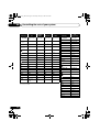
Input
function
DVD
03
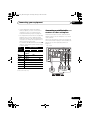
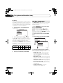
Connecting a satellite/cable
receiver or other set-top box
Satellite and cable receivers, and terrestrial
digital TV tuners are all examples of so-called
‘set-top boxes’.
When you set up the receiver you’ll need to tell
the receiver which input you connected the settop box to (see The Input Setup menu on
page 39).
VSX-1019AH
Input Terminals
HDMI DIGITAL
AUDIO
1 3
COAXIAL
ASSIGNABLE
Digital
HDMI
Component
IN 1
COAX-1a
BD
Y
Y
IN 3
IN 1 (DVD) IN 2 (CD) IN 1 (TV/SAT)
OUT
FRONT
IN
CENTER SURROUND
L
PB R
PR
IN 1
(DVD)
(BD)
IN 2
AUDIO
Y
PB
/COAXb
OPTICAL
ASSIGNABLE
ASSIGNABLE
IN 1
BD IN
ASSIGNABLE
PR
IN 2
(DVR)
ZONE2
OUT
DVD
IN
TV/SAT
IN
OUT
DVR
AUX
IN
IN
CD
IN
OUT
CD-R
R
SUBWOOFER
MULTI CH IN
IN
SPEAKERS FRONT
A
MONITOR
OUT
L
CENTER
R
SUR
IN
IR
TV/SAT
DVR
OPT-1
IN 2
CONTROL
OUT
COMPONENT
VIDEO
(HDMI-1)
HDMI 2
CD
OUT
VIDEO
IN
OPT-2
HDMI 1
HDMI
PB
PR
(HDMI-2)
3a
(HDMI-3)
COAX-2a
a.VSX-1019AH model only.
b.VSX-919AH model only.
R ANALOG L
AUDIO OUT
VIDEO OUT
COAXIAL
OPTICAL
DIGITAL OUT
Select one
STB
27
En
VSX-1019_KU.book Page 28 Thursday, January 8, 2009 12:01 PM
03
Connecting your equipment
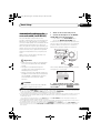
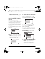
Connecting a HDD/DVD recorder,
VCR and other video sources
Connecting the multichannel
analog inputs
This receiver has two sets of audio/video inputs
and outputs suitable for connecting analog or
digital video devices, including HDD/DVD
recorders and VCRs.
For DVD Audio and SACD playback, your DVD
player may have 5.1 channel analog outputs.
Make sure that the player is set to output
multichannel analog audio.
When you set up the receiver you’ll need to tell
the receiver which input you connected the
recorder to (see also The Input Setup menu on
page 39).
VSX-1019AH
HDMI DIGITAL
AUDIO
1 3
COAXIAL
OPTICAL
ASSIGNABLE
IN 1
IN 2
IN 3
ASSIGNABLE
ASSIGNABLE
IN 1 (DVD) IN 2 (CD)
FRONT
OUT
UDIO
IN 1 (TV/SAT)
IN 2 (DVR)
CENTER SURROUND
PRE OUT
L
VSX-1019AH
R
ZONE2
OUT
IN 1
BD IN
IN 2
IN 3
IN 1 (DVD)
OUT
OUT
DVR
AUX
IN
IN
CD
IN
OUT
CD-R
SUBWOOFER
MULTI CH IN
IN
IN 2 (CD)
FRONT
ASSIGNABLE
IN 1 (TV/SAT)
IN
CENTER SURROUND
L
CENTER
R
SUBWOOFER
SURROUND
L
IR
OPTICAL
AUDIO
Y
TV/SAT
IN
R
ASSIGNABLE
E
DVD
IN
SPEAKERS FRONT
A
HDMI DIGITAL
ASSIGNABLE AUDIO
1 3
COAXIAL
IN
2 (DVR)
PRE OUT
OUT
L
IN
CONTROL
OUT
PB R
PR
IN 2
(DVR)
ZONE2
OUT
DVD
IN
TV/SAT
IN
OUT
DVR
AUX
IN
IN
CD
IN
OUT
CD-R
SUBWOOFER
SUBWOOFER
MULTI CH IN
IN
SPEAKERS FRONT
A
R
MONITOR
OUT
L
CENTER
R
SURROUND
L
IN
IR
OUT
VIDEO
IN
CONTROL
OUT
NENT
R
R ANALOG L
AUDIO IN
R ANALOG L
VIDEO IN
VIDEO OUT
AUDIO OUT
COAXIAL OPTICAL
DIGITAL OUT
Select one
HDD/DVD recorder, VCR, etc.
• In order to record, you must connect the
analog audio cables (the digital connection
is for playback only).
28
En
FRONT
OUTPUT
L
CENTER
OUTPUT
R
SURROUND
OUTPUT
L
SUBWOOFER
OUTPUT
DVD player, etc.
• If your player has 7.1-channel analog
outputs, the player’s surround back output
terminals are not used. Please refer to the
operating instructions supplied with your
component for more information.
VSX-1019_KU.book Page 29 Thursday, January 8, 2009 12:01 PM
Connecting your equipment
03
• If your turntable has line-level outputs (i.e.,
it has a built-in phono pre-amp), connect it
to the CD inputs instead.
Connecting other audio
components
This receiver has both digital and analog
inputs, allowing you to connect audio
components for playback.
This receiver features five stereo audio-only
inputs. One of these inputs have corresponding
outputs for use with audio recorders.
Most digital components also have analog
connections.
When you set up the receiver you’ll need to tell
the receiver which input you connected the
component to (see also The Input Setup menu
on page 39).
• If you’re connecting a recorder, connect
the analog audio outputs to the analog
audio inputs on the recorder.
About the WMA9 Pro decoder
This unit has an on-board Windows Media™
Audio 9 Professional1 (WMA9 Pro) decoder, so
it is possible to playback WMA9 Pro-encoded
audio using HDMI, coaxial or optical digital
connection when connected to a WMA9 Procompatible player. However, the connected
DVD player, set-top box, etc. must be able to
output WMA9 Pro format audio signals
through a coaxial or optical digital output.
VSX-1019AH
HDMI DIGITAL
AUDIO
1 3
COAXIAL
ASSIGNABLE
OPTICAL
ASSIGNABLE
IN 3
FRONT
SAT
OUT
DVR
IN
AUX
IN
CD-R
OUT
IN
CD
IN
SPEAKERS FRONT
A
R
S
ASSIGNABLE
IN 1 (DVD) IN 2 (CD) IN 1 (TV/SAT)
OUT
IN 2 (DVR)
CENTER SURROUND
SUBWOOFER
SUBWOOFER
MULTI CH IN
L
CENTER
R
PRE OUT
SURROUND
L
R
IN
IR
OUT
IN
CONTROL
OUT
R
REC L
AUDIO IN
R ANALOG L
AUDIO OUT
OPTICAL COAXIAL
DIGITAL OUT
Select one
CD-R, MD, DAT, etc.
Note
1 • Windows Media and the Windows logo are trademarks or registered trademarks of Microsoft Corporation in the United
States and/or other countries.
• With WMA9 Pro, sound problems may occur depending on your computer system. Note that WMA9 Pro 96 kHz
sources will be downsampled to 48 kHz.
29
En
VSX-1019_KU.book Page 30 Thursday, January 8, 2009 12:01 PM
03
Connecting your equipment
Connecting AM/FM antennas
Connect the AM loop antenna and the FM wire
antenna as shown below. To improve reception
and sound quality, connect external antennas
(see Connecting external antennas below).
1
Connecting external antennas
To improve FM reception connect an external
FM antenna to the FM UNBAL 75 Ω.
75 Ω coaxial cable
2
AM
LOOP
3
5
FM
UNBAL
75
AM
LOOP
ANTENNA
FM
UNBAL
75
4
ANTENNA
fig. a
fig. b
fig. c
To improve AM reception, connect a 5 m to 6 m
(16 ft. to 20 ft.) length of vinyl-coated wire to the
AM LOOP terminals without disconnecting
the supplied AM loop antenna.
For the best possible reception, suspend
horizontally outdoors.
Outdoor
antenna
1 Pull off the protective shields of both AM
antenna wires.
2 Push open the tabs, then insert one wire
fully into each terminal, then release the tabs
to secure the AM antenna wires.
3 Fix the AM loop antenna to the attached
stand.
To fix the stand to the antenna, bend in the
direction indicated by the arrow (fig. a) then
clip the loop onto the stand (fig. b).
• If you plan to mount the AM antenna to a
wall or other surface, secure the stand with
screws (fig. c) before clipping the loop to
the stand. Make sure the reception is clear.
4 Place the AM antenna on a flat surface
and in a direction giving the best reception.
5 Connect the FM wire antenna in the same
way as the AM loop antenna.
For best results, extend the FM antenna fully
and fix to a wall or door frame. Don’t drape
loosely or leave coiled up.
30
En
Indoor antenna
(vinyl-coated wire)
AM
LOOP
FM
UNBAL
75
ANTENNA
5 m to 6 m
(16 ft. to 20 ft.)
VSX-1019_KU.book Page 31 Thursday, January 8, 2009 12:01 PM
Connecting your equipment
03
Sub zone
MULTI-ZONE setup
Main zone
VSX-1019AH
This receiver can power up to two independent
systems in separate rooms after you have
made the proper MULTI-ZONE connections.
VIDEO IN
IN 1
BD IN
ASSIGNABLE
Different sources can be playing in two zones
at the same time or, depending on your needs,
the same source can also be used. The main
and sub zone have independent power (the
main zone power can be off while sub zone is
on) and the sub zone can be controlled by the
remote or front panel controls. However, you
may need to specify the volume settings in
ZONE Audio Setup on page 99.
AUDIO
Y
L
PB
PB
R
PR
IN 1
(DVD)
PR
IN 2
(DVR)
Y
ZONE2
OUT
DVD
IN
MONITOR
OUT
Y
VIDEO
PB
PR
AUDIO IN
R
COMPONENT
VIDEO
L
Making MULTI-ZONE connections
It is possible to make these connections if you
have a separate TV and speakers for the sub
zone (ZONE2). You will also need a separate
amplifier if you are not using the MULTI-ZONE
setup using speaker terminals (Zone 2) below
for the sub zone.
MULTI-ZONE listening options
The following table shows the signals that can
be output to ZONE 2:
Sub Zone Input functions available
ZONE2
Analog audio signals (AUDIO ZONE2
OUT).a
With video signals,b the composite
video (VIDEO ZONE2 OUT) signals can
be output.
MULTI-ZONE setup using speaker
terminals (Zone 2)
You must select ZONE 2 in Surround back
speaker setting on page 94 to use this setup.
Note that the sound in the sub zone will be
temporarily interrupted when controlling the
main zone (for example, changing the input
function or starting playback).
• Connect a TV monitor to the VIDEO
ZONE2 OUT jacks on this receiver.
You should have a pair of speakers attached to
the surround back speaker terminals as shown
below.
Sub zone
Main zone
VSX-1019AH
a.Any analog signal. (This does not apply for the MULTI
CH IN input.)
b.JPEG files cannot be played with the USB input.
SIRIUS IN
VIDEO IN
Basic MULTI-ZONE setup (Zone 2)
• Connect a separate amplifier to the AUDIO
ZONE2 OUT jacks and a TV monitor to the
VIDEO ZONE2 OUT jack, both on this receiver.
You should have a pair of speakers attached to
the sub zone amplifier as shown in the
following illustration.
AUDIO
Y
PB
PB R
Y
R
PR
IN 2
(DVR)
IN
AM
LOO
OUT
L
Y
PR
IN 1
(DVD)
L
IN 1VR)
BD IN
ASSIGNABLE
FM
UN
75
ZONE2 OOFER
DVD
IN
OUT
ND
L
T
R SURROUND BACK/ B L
(Single)
MONITOR
OUT
PB
VIDEO
PR
COMPONENT
VIDEO
31
En
VSX-1019_KU.book Page 32 Thursday, January 8, 2009 12:01 PM
03
Connecting your equipment
Connecting an IR receiver
If you keep your stereo components in a closed
cabinet or shelving unit, or you wish to use the
sub zone remote control in another zone, you
can use an optional IR receiver (such as a Niles
or Xantech unit) to control your system instead
of the remote sensor on the front panel of this
receiver.1
1 Connect the IR receiver sensor to the IR IN
jack on the rear of this receiver.
Closet or shelving unit
CONTROL
IR
IN
IN
OUT
HDMI
ASSIGNABLE
1 3
IN 1
BD IN
ASSIGNABLE
IN 3
Many Pioneer components have SR CONTROL
jacks which can be used to link components
together so that you can use just the remote
sensor of one component. When you use a
remote control, the control signal is passed
along the chain to the appropriate component.2
OUT
AUDIO
L
Y
Y
PB
PB R
PR
IN 1
(DVD)
Y
IN 2
• If you want to link a Pioneer component to
the IR receiver, see Operating other Pioneer
components with this unit’s sensor below
to connect to the CONTROL jacks instead
of the IR OUT jack.
Operating other Pioneer
components with this unit’s
sensor
Pioneer
component
Non-Pioneer
component
2 Connect the IR IN jack of another
component to the IR OUT jack on the rear of
this receiver to link it to the IR receiver.
Please see the manual supplied with your IR
receiver for the type of cable necessary for the
connection.
PR
IN 2
(DVR)
Important
ZONE2
OUT
DVD
IN
TV/SAT
IN
OUT
DVR
IN
AUX
IN
SP
A
MONITOR
OUT
PB
IN
IR
VIDEO
OUT
IN
PR
CD
IN
CONTROL
OUT
COMPONENT
VIDEO
VSX-1019AH
IR receiver
• Note that if you use this feature, make sure
that you also have at least one set of analog
audio, video or HDMI jacks connected to
another component for grounding purposes.
1 Decide which component you want to use
the remote sensor of.
When you want to control any component in
the chain, this is the remote sensor at which
you’ll point the corresponding remote control.
Note
1 • Remote operation may not be possible if direct light from a strong fluorescent lamp is shining on the IR receiver
remote sensor window.
• Note that other manufacturers may not use the IR terminology. Refer to the manual that came with your component
to check for IR compatibility.
• If using two remote controls (at the same time), the IR receiver’s remote sensor takes priority over the remote sensor
on the front panel.
2 • If you want to control all your components using this receiver’s remote control, see Setting the remote to control
other components on page 73.
• If you have connected a remote control to the CONTROL IN jack (using a mini-plug cable), you won’t be able to control this unit using the remote sensor.
32
En
VSX-1019_KU.book Page 33 Thursday, January 8, 2009 12:01 PM
Connecting your equipment
2 Connect the CONTROL OUT jack of that
component to the CONTROL IN jack of
another Pioneer component.
Use a cable with a mono mini-plug on each
end for the connection.
VSX-1019AH
03
Connecting your
SiriusConnect™ Tuner
To receive SIRIUS Satellite Radio broadcasts, you
will need to activate your SiriusConnect™ tuner.
VSX-1019AH
HDM
ASSIGNABLE
1 3
IN 1
BD IN
ASSIGNABLE
IN 2
IN 3
Y
PB
PB R
PR
IN 1
(DVD)
PR
IN 2
(DVR)
PRE OUT
FM
UNBAL
75
ZONE2
OUT
DVD
IN
TV/SAT
IN
OUT
DVR
AUX
IN
IN
CD
IN
SUBWOOFER
SP
ULTI CH IN
A
ENTER
MONITOR
OUT
Y
AM
LOOP
ASSIGNABLE
IN 1 (TV/SAT)
IN 2 (DVR)
CENTER SURROUND
L
Y
SIRIUS IN
OPTICAL
OUT
AUDIO
R
SUBWOOFER
SURROUND
ANTENNA
L
R SURROUND BACK / B L
(Single)
IN
Antenna
IR
OUT
VIDEO
PB
IN
CONTROL
PR
OUT
SIRIUS
H
COMPONENT
VIDEO
SIR
IUS
IN
OUT
CONTROL
IN
OUT
CONTROL
RECE
IVER
DVD
TV
BD
SOU
iPod
CD
USB
DVR
TUNE
AL
4
SEL
A.AT
CH
0
INFO
DISP
8
5
SLEE
T
DIMM
L
T
TROL
VIDE
S
O
MAS
VOLU
9
6
3
P
ER
CLAS
ENTE S
R
TER
ME
VOL
LIST
MUT
TUNE
E
TOOL
VIDEO
PARAM
S
ENTE
ETER
R
T.ED
GUID
E
TUNE
IT
PRES
ET
RETUR
N
STAND
E
LEVE
INPU
CON
ETERO
ORY
HOME
CTRL MENU
STERE
O
DVD
PHAS
MPX
O
TV
HDM
I
SIRIU
2
MCA
CC
D.AC
CESS
TV
CH
AUDI
PARAM
TOP
BAND MENU
PRES
ET
CATEG
iPod
AUTO
DIREC/ALC/
HDD T
ANT
AUDI
REMO
SETU
TE
P
RCE
CD-R
R
INPU
SELE
CT T
1
SIGN
SBch
7
ARD
CTRL
ADV MENU
SURR
PQLS
STAT
US
MEMO
CTRL
CH
RECEI
RY
VER
MAIN
ZONE
REC
EIV
ER
2
H
SiriusConnect™
HOME tuner
AC adapter
• Connect a SiriusConnect™ tuner to the
SIRIUS IN jack on the rear of this receiver.
You will also need to connect the antenna and
AC adapter to the SiriusConnect™ tuner.
Continue the chain in the same way for as
many components as you have.
33
En
VSX-1019_KU.book Page 34 Thursday, January 8, 2009 12:01 PM
03
Connecting your equipment
Connecting a component to the
front panel inputs
The front panel inputs comprise a composite
video jack (VIDEO) and stereo analog audio
inputs (AUDIO L/R). You can use these
connections for any kind of audio/video
component, but they are especially convenient
for portable equipment such as camcorders,
video games and portable audio/video
equipment.
• Push down on the PUSH OPEN tab to
access the front panel inputs.
• Select these inputs using INPUT SELECT
(remote) or the INPUT SELECTOR dial
(front panel) to select VIDEO.
USB
iPod
iPhone
VIDEO
VIDEO INPUT
L AUDIO
R
Connecting an iPod
This receiver has a dedicated iPod terminal
that will allow you to control playback of audio
content from your iPod using the controls of
this receiver.
• Switch the receiver into standby then use
the supplied iPod cable to connect your iPod
to the iPod/iPhone/USB terminal on the front
panel of this receiver.
• Push down on the PUSH OPEN tab to
access the iPod/iPhone/USB terminal.
• It is also possible to connect using the
cable included with the iPod, but in this
case it is not possible to view pictures via
the receiver.
• For the cable connection, refer to also the
operating instructions for iPod.
MCACC
SETUP MIC
USB
SPEAKERS
USB
MULTI-ZONE
CONTROL
ON / OFF
iPod
iPhone
VIDEO
VIDEO INPUT
L AUDIO
iPod
iPhone
VIDEO
VIDEO INPUT
L AUDIO
R
MCACC
SETUP MIC
MASTER
VOLUME
R
MCACC
SETUP MIC
SPEAKERS
USB
MULTI-ZONE
CONTROL
ON / OFF
iPod
iPhone
VIDEO
VIDEO INPUT
L AUDIO
MASTER
VOLUME
R
MCACC
SETUP MIC
This receiver
This receiver
TV game, video camera,
etc.
VIDEO
AUDIO
OUTPUT
iPod cable
(supplied)
MENU
34
En
iPod
VSX-1019_KU.book Page 35 Thursday, January 8, 2009 12:01 PM
Connecting your equipment
03
Connecting a USB device
Plugging in the receiver
It is possible to playback files using the USB
interface on the front of this receiver.
Only plug in after you have connected all your
components to this receiver, including the
speakers.
• Switch the receiver into standby then
connect your USB device to the iPod/iPhone/
USB terminal on the front panel of this
receiver.
• Push down on the PUSH OPEN tab to
access the iPod/iPhone/USB terminal.
iPod
iPhone
USB
SPEAKERS
USB
VIDEO
VIDEO INPUT
L AUDIO
R
MCACC
SETUP MIC
MULTI-ZONE
CONTROL
ON / OFF
iPod
iPhone
VIDEO
VIDEO INPUT
L AUDIO
MASTER
VOLUME
R
MCACC
SETUP MIC
This receiver
USB mass
storage device
• Plug the AC power cord into a convenient
AC power outlet.1
CAUTION
• Handle the power cord by the plug part. Do
not pull out the plug by tugging the cord,
and never touch the power cord when your
hands are wet, as this could cause a short
circuit or electric shock. Do not place the
unit, a piece of furniture, or other object on
the power cord or pinch the cord in any
other way. Never make a knot in the cord or
tie it with other cables. The power cords
should be routed so that they are not likely
to be stepped on. A damaged power cord
can cause a fire or give you an electric
shock. Check the power cord once in a
while. If you find it damaged, ask your
nearest Pioneer authorized independent
service company for a replacement.
• The receiver should be disconnected by
removing the mains plug from the wall
socket when not in regular use, e.g., when
on vacation.
• Make sure the blue STANDBY/ON light
has gone out before unplugging.
• If you have connected speakers with a 6 Ω
impedance, change the impedance setting
before turning on the power.
Note
1 After this receiver is connected to an AC outlet, a 2 second to 10 second HDMI initialization process begins. You
cannot carry out any operations during this process. The HDMI indicator in the front panel display blinks during this
process, and you can turn on this receiver once it has stopped blinking. When you set the KURO LINK mode to OFF,
you can skip this process. For details about the KURO LINK feature, see KURO LINK on page 60.
35
En
VSX-1019_KU.book Page 36 Thursday, January 8, 2009 12:01 PM
04
Basic Setup
Chapter 4:
Basic Setup
Switching the speaker impedance
We recommend using speakers of 8 Ω with this
system, but it is possible to switch the
impedance setting if you plan to use speakers
with a 6 Ω impedance rating.
1
2 Select ‘System Setup’ from the HOME
MENU.
3 Select ‘OSD Language’ from the System
Setup menu.
4.SystemSetup
A/V RECEIVER
a.Manual SP Setup
b. Input Setup
c. OSD Language
d. Other Setup
Switch the receiver into standby.
2 While holding down ENTER on the front
panel, press STANDBY/ON.
The display shows RESET NO .
4c.OSD Language
A/V RECEIVER
Language :
Exit
Use TUNE +/– (or / on the remote control)
to select SPEAKER 8Ω , and then use
PRESET +/– (or / on the remote control) to
select SPEAKER 8Ω or SPEAKER 6Ω.
• SPEAKER 8Ω – Use this setting if your
speakers are rated at 8 Ω or more.
English
Return
OK
Exit
4
• SPEAKER 6Ω – Use this setting if your
speakers are rated at 6 Ω.
Return
Select the desired language.
• English
• French
• German
• Italian
Changing the OSD display
language (OSD Language)
• Spanish
• Dutch
The language used on the on-screen display
can be changed.
• The explanations in these operating
instructions are for when English is
selected for the OSD.
• Russian
5
Select ‘OK’ to change the language.
4c.OSD Language
A/V RECEIVER
Language :
1 Press RECEIVER on the remote control,
then press HOME MENU.
A Graphical User Interface (GUI) screen
appears on your TV. Use /// and
ENTER to navigate through the screens and
select menu items. Press RETURN to exit the
current menu.
36
En
English
OK
Exit
Return
The setting is completed and the System Setup
menu reappears automatically.
VSX-1019_KU.book Page 37 Thursday, January 8, 2009 12:01 PM
Basic Setup
Automatically setting up for
surround sound (Auto MCACC)
The Auto MCACC Setup measures the
acoustic characteristics of your listening area,
taking into account ambient noise, speaker
connection and speaker size, and tests for both
channel delay and channel level. After you
have set up the microphone provided with your
system, the receiver uses the information from
a series of test tones to optimize the speaker
settings and equalization for your particular
room.
Make sure you do this before moving on to
Playing a source on page 41.
04
1
Switch on the receiver and your TV.
2 Connect the microphone to the MCACC
SETUP MIC jack on the front panel.
• Push down on the PUSH OPEN tab to
access the MCACC SETUP MIC jack.
Place the microphone so that it’s about ear level
at your normal listening position (use a tripod if
possible). Make sure there are no obstacles
between the speakers and the microphone.
USB
SPEAKERS
USB
iPod
iPhone
VIDEO
VIDEO INPUT
L AUDIO
R
MCACC
SETUP MIC
MULTI-ZONE
CONTROL
ON / OFF
iPod
iPhone
VIDEO
MASTER
VOLUME
VIDEO INPUT
L AUDIO
R
MCACC
SETUP MIC
Important
• Make sure the microphone and speakers
are not moved during the Auto MCACC
Setup.
• Using the Auto MCACC Setup will
overwrite any existing settings for the
MCACC preset you select.
• Before using the Auto MCACC Setup, the
headphones should be disconnected and
the iPod/USB or SIRIUS Radio function
should not be selected as an input
function.
The Full Auto MCACC display appears once the
microphone is connected.1
1a.Full Auto MCACC
A/V RECEIVER
Surr Back System :
Normal
Save SYMMETRY to : M1.MEMORY 1
START
Exit
CAUTION
• The test tones used in the Auto MCACC
Setup are output at high volume.
Return
3 Select Surr Back System setting,2 select
an MCACC preset3, press RECEIVER and then
select START.4
Note
1 • You can’t use the HOME MENU when the iPod/USB or SIRIUS Radio input function is selected (in either the main
or sub zone). When you set ZONE 2 to ON (page 69), you can’t use the HOME MENU.
• If you leave the GUI screen for over five minutes, the screen saver will appear.
2 • If you are planning on bi-amping your front speakers, or setting up a separate speaker system in another room, read
through Surround back speaker setting on page 94 and make sure to connect your speakers as necessary before
continuing to step 4.
• If you have THX-certified speakers, select Return, then select Auto MCACC for the THX Speaker setting. See
Automatic MCACC (Expert) on page 78 for more on this.
3 The six MCACC presets are used for storing surround sound settings for different listening positions. Simply choose
an unused preset for now (you can rename it later in Data Management on page 91).
4 Note that correction curves are saved only when set to SYMMETRY. Select Return, then select Auto MCACC to save
other correction curves (such as ALL CH ADJ and FRONT ALIGN). See Automatic MCACC (Expert) on page 78 for
more on this.
37
En
VSX-1019_KU.book Page 38 Thursday, January 8, 2009 12:01 PM
04
Basic Setup
Select Normal (Surround back), Speaker B,
Front Bi-Amp or ZONE 2 for the Surr Back
System setting according to connections to
the surround back speaker terminals.
4 Follow the instructions on-screen.
Make sure the microphone is connected, and if
you’re using a subwoofer, make sure it is switched
on and set to a comfortable volume level.
5 Wait for the test tones to finish, then
confirm the speaker configuration in the GUI
screen.
A progress report is displayed on-screen while
the receiver outputs test tones to determine the
speakers present in your setup. Try to be as
quiet as possible while it’s doing this.1
If no operations are performed for 10 seconds
while the speaker configuration check screen
is being displayed, the Auto MCACC Setup will
resume automatically. In this case, you don’t
need to select ‘OK’ and press ENTER in step 6.
• With error messages (such as Too much
ambient noise! or Check microphone.)
select RETRY after checking for ambient
noise (see Problems when using the Auto
MCACC Setup below) and verifying the mic
connection. If there doesn’t seem to be a
problem, you can simply select GO NEXT
and continue.
The configuration shown on-screen should
reflect the actual speakers you have.
• If you see an ERR message (or the speaker
configuration displayed isn’t correct), there
may be a problem with the speaker
connection.
If selecting RETRY doesn’t work, turn off
the power and check the speaker
connections. If there doesn’t seem to be a
problem, you can simply use / to select
the speaker and / to change the
setting and continue.
• If Reverse Phase is displayed, the
speaker’s wiring (+ and –) may be inverted.
Check the speaker connections.2
If the connections were wrong, turn off the
power, disconnect the power cable, then
reconnect properly. After this, perform the
Full Auto MCACC procedure again.
6 Make sure ‘OK’ is selected, then press
ENTER.
A progress report is displayed on-screen while
the receiver outputs more test tones to
determine the optimum receiver settings for
Channel Level, Speaker Distance, Standing
Wave and Acoustic Cal EQ.
Again, try to be as quiet as possible while this
is happening. It may take 3 to 10 minutes.
1a.Full Auto MCACC
A/V RECEIVER
Now Analyzing...
2/10
Environment Check
Ambient Noise
: OK
Microphone
:
Speaker YES/NO :
1a.Full Auto MCACC
A/V RECEIVER
Exit
L
C
R
SR
SBR
SBL
SL
SW
10
OK
Exit
:
:
:
:
:
:
:
:
YES
YES
YES
YES
YES
YES
YES
YES
Cancel
RETRY
Cancel
Note
1 Do not adjust the volume during the test tones. This may result in incorrect speaker settings.
2 If the speaker is not pointed to the microphone (listening position) or when using speakers that affect the phase
(dipole speakers, reflective speakers, etc.), Reverse Phase may be displayed even if the speakers are properly
connected. If this happens, select GO NEXT and continue.
38
En
VSX-1019_KU.book Page 39 Thursday, January 8, 2009 12:01 PM
Basic Setup
7 The Auto MCACC Setup procedure is
completed and the Home Menu menu
reappears automatically.1
Be sure to disconnect the microphone from
this receiver upon completion of the Auto
MCACC Setup.
The settings made in the Auto MCACC Setup
should give you excellent surround sound from
your system, but it is also possible to adjust
these settings manually using The Advanced
MCACC menu on page 77 or The system and
the other setup on page 93.2
Problems when using the Auto
MCACC Setup
If the room environment is not optimal for the
Auto MCACC Setup (too much background
noise, echo off the walls, obstacles blocking
the speakers from the microphone) the final
settings may be incorrect. Check for household
appliances (air conditioner, fridge, fan, etc.),
that may be affecting the environment and
switch them off if necessary. If there are any
instructions showing in the front panel display,
please follow them.
• Some older TVs may interfere with the
operation of the microphone. If this seems
to be happening, switch off the TV when
doing the Auto MCACC Setup.
The Input Setup menu
You only need to make settings in the Input
Setup menu if you didn’t hook up your digital
equipment according to the default settings
(see Input function default and possible
settings on page 40). In this case, you need to
04
tell the receiver what equipment is hooked up
to which terminal so the buttons on the remote
control correspond to the components you’ve
connected.
1 Switch on the receiver and your TV.
Use RECEIVER to switch on.
2 Press RECEIVER on the remote control,
then press HOME MENU.
A Graphical User Interface (GUI) screen
appears on your TV. Use /// and
ENTER to navigate through the screens and
select menu items. Press RETURN to confirm
and exit the current menu.
3 Select ‘System Setup’ from the HOME
MENU.
4 Select ‘Input Setup’ from the System
Setup menu.
4.SystemSetup
A/V RECEIVER
a.Manual SP Setup
b. Input Setup
c. OSD Language
d. Other Setup
4b.Input Setup
A/V RECEIVER
Exit
INPUT
Input Name
Input Skip
:
:
:
DVD
Rename
OFF
Digital In
HDMI Input
Component In
:
:
:
COAX-1
Return
--Comp-1
Exit
Finish
5 Select the input function that you want to
set up.
The default names correspond with the names
next to the terminals on the rear panel (such as
DVD or VIDEO) which, in turn, correspond
with the names on the remote control.
Note
1 You can also choose to view the settings from the MCACC Data Check screen. See Checking MCACC Data on page 89
for more on this.
2 • Depending on the characteristics of your room, sometimes identical speakers with cone sizes of around 12 cm (5
inches) will end up with different size settings. You can correct the setting manually using the Manual speaker setup
on page 94.
• The subwoofer distance setting may be farther than the actual distance from the listening position. This setting
should be accurate (taking delay and room characteristics into account) and generally does not need to be changed.
• If Auto MCACC Setup measurement results are incorrect due to the interaction of the speakers and viewing
environment, we recommend adjusting the settings manually.
39
En
VSX-1019_KU.book Page 40 Thursday, January 8, 2009 12:01 PM
04
Basic Setup
6 Select the input(s) to which you’ve
connected your component.
For example, if your DVD player only has an
optical output, you will need to change the
DVD input function’s Digital In setting from
COAX-1 (VSX-1019AH model)/COAX (VSX919AH model) (default) to the optical input
you’ve connected it to.The numbering (OPT-1
to 2) corresponds with the numbers beside the
inputs on the back of the receiver.
• If your component is connected via a
component video cable to an input
terminal other than the default, you must
tell the receiver which input terminal your
component is connected to, or else you
may see the composite video signals
instead of the component video signals.1
7 When you’re finished, proceed to the
settings for other inputs.
There are three optional settings in addition to
the assignment of the input jacks:
• Input Name – You can choose to rename
the input function for easier identification.
Select Rename to do so, or Default to
return to the system default.
• Input Skip – When set to ON, that input is
skipped when selecting the input using
INPUT SELECT. (DVD and other inputs can
be still be selected directly with the input
function buttons.)
Input function default and possible
settings
The terminals on the receiver generally
correspond to the name of one of the input
functions. If you have connected components
to this receiver differently from (or in addition
to) the defaults below, see The Input Setup
menu on page 39 to tell the receiver how you’ve
connected up. The dots () indicate possible
assignments.
Input
function
DVD
IN 1
(BD)
TV/SAT
OPT-1
c
DVR
OPT-2
c
IN 2
VIDEO
HDMI 1
(HDMI-1)
HDMI 2
(HDMI-2)
HDMI
3a
(HDMI-3)
iPod/USB
CD
CD-R/TAPE
COAX-2a
TUNER
MULTI CH IN
INPUT
Input Name
Input Skip
:
:
:
DVD
Rename
OFF
SIRIUS
Digital In
HDMI Input
Component In
:
:
:
COAX-1
--Comp-1
Finish
Component
c
BD
A/V RECEIVER
Exit
HDMI
COAX-1a
/COAXb
AUX
4b.Input Setup
Input Terminals
Digital
c
a.VSX-1019AH model only.
b.VSX-919AH model only.
c.With KURO LINK set to ON, assignments cannot be
made (see KURO LINK on page 60).
8 When you’re finished, press RETURN.
You will return to the System Setup menu.
Note
1 For high-definition video (using component video connections), or when digital video conversion is switched off (in
Setting the Video options on page 67), you must connect your TV to this receiver using the same type of video cable as
you used to connect your video component.
40
En
VSX-1019_KU.book Page 41 Thursday, January 8, 2009 12:01 PM
Basic playback
05
Chapter 5:
Basic playback
Playing a source
Here are the basic instructions for playing a
source (such as a DVD disc) with your home
theater system.
1 Switch on your system components and
receiver.
Start by switching on the playback component
(for example a DVD player), your TV1 and
subwoofer (if you have one), then the receiver
(press RECEIVER).
• Make sure the setup microphone is
disconnected.
2 Select the input function you want to
play.
You can use the input function buttons on the
remote control, INPUT SELECT, or the front
panel INPUT SELECTOR dial.2
It is possible to check on the front panel display
whether or not multi-channel playback is being
performed properly.
When using a surround back speaker,
2D+PLIIx MOVIE is displayed when playing
Dolby Digital signals, and DTS+Neo:6 is
displayed when playing DTS 5.1-channel signals.
When not using a surround back speaker,
DOLBY DIGITAL is displayed when playing
Dolby Digital signals.
If the display does not correspond to the input
signal and listening mode, check the
connections and settings.
4 Use the volume control to adjust the
volume level.
Turn down the volume of your TV so that all
sound is coming from the speakers connected
to this receiver.
3 Press AUTO/ALC/DIRECT (AUTO SURR/
ALC/STREAM DIRECT) to select ‘AUTO
SURROUND’ and start playback of the
source.3
If you’re playing a Dolby Digital or DTS surround
sound DVD disc, you should hear surround
sound. If you are playing a stereo source, you
will only hear sound from the front left/right
speakers in the default listening mode.
• See also Listening to your system on
page 53 for information on different ways
of listening to sources.
Note
1 Make sure that the TV’s video input is set to this receiver (for example, if you connected this receiver to the VIDEO
jacks on your TV, make sure that the VIDEO input is now selected).
2 If you need to manually switch the input signal type press SIGNAL SEL (page 58).
3 • You may need to check the digital audio output settings on your DVD player or digital satellite receiver. It should be
set to output Dolby Digital, DTS and 88.2 kHz / 96 kHz PCM (2 channel) audio, and if there is an MPEG audio option,
set this to convert the MPEG audio to PCM.
• Depending on your DVD player or source discs, you may only get digital 2 channel stereo and analog sound. In this
case, the receiver must be set to a multichannel listening mode (see Listening in surround sound on page 53 if you
need to do this) if you want multichannel surround sound.
41
En
VSX-1019_KU.book Page 42 Thursday, January 8, 2009 12:01 PM
05
Basic playback
Playing a source with HDMI
connection
• Use INPUT SELECT to select the HDMI
input you’ve connected to (for example,
HDMI 1).
You can also perform the same operation by
using the INPUT SELECTOR dial on the front
panel or by pressing HDMI on the remote
control repeatedly.
• Set the HDMI parameter in Setting the
Audio options on page 64 to THROUGH if
you want to hear HDMI audio output from
your TV or flat panel TV (no sound will be
heard from this receiver).
• If the video signal does not appear on your
TV or flat panel TV, try adjusting the
resolution settings on your component or
display. Note that some components (such
as video game units) have resolutions that
may not be converted. In this case, use an
analog video connection.
Selecting the multichannel analog
inputs
If you have connected a decoder or a DVD
player as above, you must select the analog
multichannel inputs for surround sound
playback.1
1 Make sure you have set the playback
source to the proper output setting.
For example, you might need to set your DVD
player to output multichannel analog audio.
2 Use INPUT SELECT to select MULTI CH IN.
You can also use the INPUT SELECTOR dial on
the front panel.
• Depending on the DVD player you’re using,
the analog output level of the subwoofer
channel may be too low. In this case, the
output level of the subwoofer can be
increased by 10 dB in the Multi Ch In
Setup in Other Setup. For details, see
Multi Channel Input Setup on page 99.
Note
1 • When playback from the multichannel inputs is selected, only the volume and channel levels can be set.
• You can’t listen to your speaker B system during playback from the multichannel inputs.
• With MULTI CH IN inputs, it is possible to play pictures simultaneously. For details, see Multi Channel Input Setup
on page 99.
42
En
VSX-1019_KU.book Page 43 Thursday, January 8, 2009 12:01 PM
Basic playback
05
Playing back audio files stored on an iPod
Playing an iPod
This receiver has a dedicated iPod terminal that
will allow you to control playback of audio content
from your iPod using the controls of this receiver.1
1 Switch on the receiver and your TV.
See Connecting an iPod on page 34.
2 Press iPod USB on the remote control to
switch the receiver to the iPod/USB.
Loading appears in the GUI screen while the
receiver verifies the connection and retrieves
data from the iPod.
When the display shows iPod top menu you’re
ready to play music from the iPod.2
• Main Zone:
To navigate songs on your iPod, you can take
advantage of the GUI screen of your TV connected
to this receiver.3 You can also control all operations
for music in the front panel display of this receiver.
Finding what you want to play
When your iPod is connected to this receiver,
you can browse songs stored on your iPod by
playlist, artist name, album name, song name,
genre or composer, similar to using your iPod
directly.
1 Use / to select a category, then press
ENTER to browse that category.
• To return to the previous level any time,
press RETURN.
2 Use / to browse the selected category
(e.g., albums).
• Use / to move to previous/next levels.
iPod
A/V RECEIVER
Playlists
Artists
Albums
Songs
Podcasts
Genres
Composers
Audiobooks
1/ 9
3 Continue browsing until you arrive at
what you want to play, then press to start
playback.4
• Main Zone:
iPod CTRL
• Sub Zone (VSX-1019AH model only):
Track Title
Top Menu
PLAY
iPod
xxxx/xxxx
3:02
-2:02
Artist Name
Shuffle On
Album Title
[
[
[
[
[
[
[
[
Playlists
Artists
Albums
Songs
Podcasts
Genres
Composers
Audiobooks
1/9
]
]
]
]
]
]
]
]
Track number
Track title
Play mode
Artist name
Album title
iPod
Now Playing
Playing time
File information
Genre : xxxxxxxxxxx
Chapter Number : xxx/xxx
iPod CTRL
List
Note
1 • This system is compatible with the audio and the video of the iPod nano, iPod fifth generation, iPod classic, iPod
touch and iPhone (iPod shuffle is not supported). However, that some of the functions may be restricted for some
models. Note, however, compatibility may vary depending on the software version of your iPod and iPhone. Please be
sure to use the latest available software version.
• iPod and iPhone are licensed for reproduction of non-copyrighted materials or materials the user is legally permitted
to reproduce.
• Features such as the equalizer cannot be controlled using this receiver, and we recommend switching the equalizer
off before connecting.
• Pioneer cannot under any circumstances accept responsibility for any direct or indirect loss arising from any
inconvenience or loss of recorded material resulting from the iPod failure
2 • The controls of your iPod will be inoperable when connected to this receiver.
• VSX-919AH model only: iPod/USB function cannot be selected for the MULTI-ZONE feature (page 69).
3 • Note that characters that cannot be displayed on this receiver are displayed as #.
• This feature is not available for photos or video clips on your iPod. To display video clips, switch iPod operation to
the iPod (see Switching the iPod controls on page 44).
4 If you’re in the song category, you can also press ENTER to start playback.
43
En
VSX-1019_KU.book Page 44 Thursday, January 8, 2009 12:01 PM
05
Basic playback
• Sub Zone (VSX-1019AH model only):
Play
xxxx/xxxx
Chap xxx/xxx
Track Title
Shuffle On
3:02
-2:02
Artist Name
Album Title
Track number
File information
Track title
Play mode
Playing time
Artist name
Album title
Button
Press repeatedly to switch between
Repeat One, Repeat All and Repeat Off.
Press repeatedly to switch between
Shuffle Songs, Shuffle Albums and
Shuffle Off.
DISP
Press repeatedly to change the song
playback information displayed in the
front panel display.
ENTER
When browsing, press to move to next
levels. During playback, press to set the
play and pause modes.
Navigation through categories on your iPod
looks like this:
Playlists Songs
Artists Albums Songs
Albums Songs
Songs
Podcasts
Genres Artists Albums Songs
Composers Albums Songs
Audiobooks
Shuffle Songs
RETURN When browsing, press to move to
previous levels.
/
When browsing, press to move to
previous/next levels.
/
During Audiobook playback, press to
switch the playback speed: Faster
Normal Slower
TOP
MENU
Press to return to the iPod top menu
screen.
Tip
• You can play all of the songs in a particular
category by selecting the All item at the top
of each category list. For example, you can
play all the songs by a particular artist.
Basic playback controls
The following table shows the basic playback
controls for your iPod. Press iPod USB to
switch the remote control to the iPod/USB
operation mode.
Button
What it does
Press to start playback.
If you start playback when something
other than a song is selected, all the
songs that fall into that category will play.
Pauses/unpauses playback.
What it does
Switching the iPod controls1
You can switch over the iPod controls between
the iPod and the receiver.
1 Press iPod CTRL to switch the iPod
controls.2
This enables operation and display on your
iPod, and this receiver’s remote control and
GUI screen become inactive.
2 Press iPod CTRL again to switch back to
the receiver controls.
/ Press and hold during playback to start
scanning.
/ Press to skip to previous/next track.
Note
1 You cannot use this function, when an iPod of fifth generation or iPod nano of first generation is connected.
2 When this function is set, iPod images cannot be played on this receiver. However, when video clips recorded on the
iPod are played, the playback picture is displayed.
44
En
VSX-1019_KU.book Page 45 Thursday, January 8, 2009 12:01 PM
Basic playback
05
Important
Playing a USB device
1
It is possible to playback files using the USB
interface on the front of this receiver.
1 Switch on the receiver and your TV.
See Connecting a USB device on page 35.2
2 Press iPod USB on the remote control to
switch the receiver to the iPod/USB.
Loading appears in the GUI screen as this
receiver starts recognizing the USB device
connected.3 When the display shows USB Top
menu you’re ready to playback from the USB
device.
• Main Zone:
USB Top
A/V RECEIVER
Music
Photos
Slideshow Setup
If an Over Current message lights in the
display, the power requirements of the USB
device are too high for this receiver. Try
following the points below:
• Switch the receiver off, then on again.
• Reconnect the USB device with the
receiver switched off.
• Use a dedicated AC adapter (supplied with
the device) for USB power.
If this doesn’t remedy the problem, it is likely
your USB device is incompatible.
Playing back audio files stored on a
USB memory device
The maximum number of levels that you can
select in Step 2 (below) is 8. Also, you can
display and play back up to 30 000 folders and
files within a USB memory device.4
1/3
• Sub Zone (VSX-1019AH model only):
USB Top
[ Music
[ Photos
[ Slideshow Setup
]
]
]
1/3
Note
1 • Compatible USB devices include external magnetic hard drives, portable flash memory (particularly keydrives) and
digital audio players (MP3 players) of format FAT16/32. It is not possible to connect this unit to a personal computer
for USB playback.
• Pioneer cannot guarantee compatibility (operation and/or bus power) with all USB mass storage devices and
assumes no responsibility for any loss of data that may occur when connected to this receiver.
2 Make sure the receiver is in standby when disconnecting the USB device.
3 • If the file selected cannot be played back, this receiver automatically skips to the next file playable.
• When the file currently being played back has no title assigned to it, the file name is displayed in the GUI screen
instead; when neither the album name nor the artist name is present, the row is displayed as a blank space.
• Note that non-roman characters in the playlist are displayed as #.
• VSX-919AH model only: iPod/USB function cannot be selected for the MULTI-ZONE feature (page 69).
• If this error occurs, playback is interrupted and the next playable file is played automatically.
• This error may occur if the title information is changed on a computer, etc.
4 • Playback stops when the last song in a USB memory device is played back to the end.
• When a USB memory device with a large capacity is connected, it may take some time to read all the contents.
• This receiver does not support a USB hub.
• Copyrighted audio files cannot be played back on this receiver.
• DRM-protected audio files cannot be played back on this receiver.
45
En
VSX-1019_KU.book Page 46 Thursday, January 8, 2009 12:01 PM
05
Basic playback
1 Use / to select ‘Music’ from the USB
Top menu.
USB Top
A/V RECEIVER
Music
Photos
Slideshow Setup
Music
Top Menu
Basic playback controls
The following table shows the basic playback
controls for your USB memory device. Press
iPod USB to switch the remote control to the
iPod/USB operation mode.
Button
What it does
Press to start playback.
Pauses/unpauses playback.
A/V RECEIVER
Folder1
Folder2
Folder3
Music1
Music2
Music3
Music4
Music5
1/ 9
1/3
/ Press and hold during playback to start
scanning.
Return
/ Press to skip to previous/next track.
Press repeatedly to switch between
Repeat One, Repeat Folder, Repeat All
and Repeat Off.
2 Use / to select a folder, then press
ENTER to browse that folder.
• To return to the previous level any time,
press RETURN.
3 Continue browsing until you arrive at
what you want to play, then press to start
playback.
• Main Zone:
Press repeatedly to switch between
Random On and Random Off.
DISP
Press repeatedly to change the song
playback information displayed in the
front panel display.
ENTER
When browsing, press to move to next
levels. During playback, press to set the
play and pause modes.
Track number
Track title or File name
Track Title
Top Menu
PLAY
xxxx/xxxx
3:02
-2:02
Artist Name
Random On
Album Title
Playing time
Play mode
Artist name
Album title or Folder
name
USB
Now Playing
Genre : xxxxxxxxxxx
Format : xxxxxxxxxxx
Bit Rate : xxxxxxxxxxx
File information
Return
• Sub Zone (VSX-1019AH model only):
Track title or File name
Play
xxxx/xxxx
Track Title
Track number
Play mode
Random On
3:02
-2:02
Artist Name
Album Title
46
En
Playing time
Album title or Folder
name
Artist name
RETURN When browsing, press to move to
previous levels.
/
When browsing, press to move to
previous/next levels.
TOP
MENU
Press to return to the USB Top menu.
VSX-1019_KU.book Page 47 Thursday, January 8, 2009 12:01 PM
Basic playback
Playing back photo files stored on a
USB memory device1
1 Use / to select ‘Photos’ from the USB
Top menu.
05
Slideshow Setup
Make the various settings for playing
slideshows of photo files here.
1 Use / to select ‘Slideshow Setup’
from the USB Top menu.
USB Top
A/V RECEIVER
USB Top
Music
Photos
Slideshow Setup
A/V RECEIVER
Music
Photos
Slideshow Setup
Top Menu
Slideshow Setup
A/V RECEIVER
1/3
1/3
2 Use / to select a folder, then press
ENTER to browse that folder.
• To return to the previous level any time, press
RETURN.
3 Continue browsing until you arrive at
what you want to play, then press to start
playback.2
The selected content is displayed in full screen
and starts a slideshow.
Theme
Interval
BGM
Music Select
Folder1
:
:
:
:
Normal(OFF)
5 sec
ON
Select
Return
Return
2
Select the setting you want.
• Theme – Add various effects to the
slideshow.
• Interval – Set the interval for switching the
photos. This may not be available
depending on the Theme setting.
After a slideshow launches, pressing ENTER
toggles between play and pause.
• BGM – Play music files stored on the USB
device while displaying photos.
Basic playback controls
• Music Select – Select the folder containing
the music files to be played when BGM is
set to ON.
Button(s) Function
ENTER, Starts displaying a photo and playing a
slideshow.
RETURN,
Stops the Player and returns to the
previous menu.
Displays the previous photo content
Display the next photo content
Pauses/unpauses the slideshow
3 When you’re finished, press RETURN.
You will return to the USB Top menu.
Note
1 VSX-1019AH model only: Photo files cannot be played in the sub zone.
2 If the slideshow is left in the pause mode for five minutes, the list screen reappears.
47
En
VSX-1019_KU.book Page 48 Thursday, January 8, 2009 12:01 PM
05
Basic playback
About playable file formats
The USB function of this receiver supports the following file formats. Note that some file formats are not
available for playback although they are listed as playable file formats.
Music files
Category
Extension
Stream
MP3a
.mp3
MPEG-1, 2, 2.5 Audio
Layer-3
WAV
WMA
.wav
.wma
LPCM
WMA8/9b
Sampling frequency
8 kHz to 48 kHz
Quantization bitrate
16 bit
Channel
2 ch
Bitrate
8 kbps to 320 kbps
VBR/CBR
Supported/Supported
Sampling frequency
32 kHz, 44.1 kHz, 48 kHz
Quantization bitrate
8 bit, 16 bit, 20 bit, 24 bit
Channel
2 ch, Monaural
Sampling frequency
8 kHz to 48 kHz
Quantization bitrate
16 bit
Channel
2 ch
Bitrate
8 kbps to 320 kbps
VBR/CBR
Supported/Supported
a.“MPEG Layer-3 audio decoding technology licensed from Fraunhofer IIS and Thomson multimedia.”
b.Files encoded using Windows Media Codec 9 may be playable but some parts of the specification are not supported;
specifically, Pro, Lossless, Voice.
Photo files
48
En
Category
Extension
JPEG
.jpg
.jpeg
.jpe
.jif
.jfif
Format
Meeting the following conditions:
• Baseline JPEG format (including files recorded in Exif/DCF
format)
• Y:Cb:Cr - 4:4:4, 4:2:2 or 4:2:0
Resolution
30 to 8192 pixels vertical, 40 to 8192 pixels horizontal
VSX-1019_KU.book Page 49 Thursday, January 8, 2009 12:01 PM
Basic playback
05
Listening to SIRIUS Radio
Using SIRIUS Radio
With SIRIUS you get The Best Radio on Radio™
with all your favorite entertainment including
100 % commercial-free music, plus superior
sports coverage, uncensored talk and comedy,
world-class entertainment, news, weather and
more for your car, home or office. For more
information visit sirius.com or siriuscanada.ca
SIRIUS is available in the US for subscribers
with addresses in the continental US and is
available in Canada for subscribers with a
Canadian address. Required subscription plus
compatible SIRIUS tuner and antenna are
required and sold separately. SIRIUS
Programming is subject to change. Visit http:/
/www.sirius.com for the most complete and
up-to-date channel lineup and product
information.
1
• Press SIRIUS to switch to the SIRIUS input.
For best reception, you may need to move the
SiriusConnect™ tuner antenna near a window
(refer to the manual for the SiriusConnect™
Home tuner for antenna placement
recommendations).
• If after pressing SIRIUS the display shows
Antenna Error, try disconnecting the
antenna and reconnecting.2 If the display
shows Check Sirius Tuner, check the
connection of the AC adapter and this
receiver to the SiriusConnect™ tuner.
After connecting, you will be able to use this
receiver to select channels and navigate
categories using the GUI screen.3 The
information displayed is as follows:
• Main Zone:
Preset class
Song name
Top Menu
Johnny B. Goode
Preset
Signal strength
Preset Class : A
Artist name
Chuck Berry
Fifties (50’s)
A1
123
Preset Number
Channel Number
Channel name
Channel number
Category
Category : Decades
Composer : Chuck Berry
Composer name
Category
Preset number
• Sub Zone (VSX-1019AH model only):
Channel name
Song name
Preset class
Signal strength
Johnny B. Goode
A
Chuck Berry
Fifties (50’s)
Decades
A1
123
Artist name
Preset number
Channel number
Chuck Berry
Composer name
Category
Note
1 • In order to activate your radio subscription, you will need the SIRIUS ID (SID) which uniquely identifies your tuner.
The SID may be found on a sticker located on the packaging, or on the bottom of the tuner itself. The label will have
a printed 12-digit SID number. When you have located the SID, write it down in the space provided near the end of
this manual. Contact SIRIUS on the internet at: https://activate.siriusradio.com
• Follow the prompts to activate your subscription, or you can also call SIRIUS toll-free at 1-888-539-SIRIUS (1-888539-7474).
• Select 0 (SIRIUS ID) from the GUI screen to check the Radio ID of the SIRIUS Connect tuner (see Selecting channels
and browsing by genre below).
2 You can check the strength of reception in Using the SIRIUS Menu on page 51.
3 It’s easiest if you have your TV switched on to take advantage of the GUI screens. You can, however, use just the front
panel display to do everything if you prefer.
49
En
VSX-1019_KU.book Page 50 Thursday, January 8, 2009 12:01 PM
05
Basic playback
Selecting channels and browsing by genre
Saving channel presets
From the SIRIUS Channel Guide, you can
browse SIRIUS Radio channels in the order
that they appear, or you can narrow your
channel search by genre.
This receiver can memorize up to 63 channels,
stored in seven banks, or classes (A to G) of 9
channels each.
• Main Zone:
Channel Guide
1 Select the channel you want to memorize.
See Selecting channels and browsing by genre
above.
A/V RECEIVER
184
185
186
187
188
192
193
198
Weather
TWN
Hardcore Sports
InfoPlus
RCI Plus
Rock Velours
energie2
Playboy
2 Press T.EDIT.
The display shows a blinking memory class.
Exit
• Sub Zone (VSX-1019AH model only):
3 Press CLASS to select one of the seven
classes, then press / to select the channel
preset you want.
You can also use the number buttons to select
a preset.
Channel Guide
[ 184
[ 185
[ 186
[ 187
[ 188
[ 192
[ 193
[ 198
1/xxx
Weather
TWN
Hardcore Sports
InfoPlus
RCI Plus
Rock Velours
energie2
Playboy
]
]
]
]
]
]
]
]
1 Press / to enter the SIRIUS Channel
Guide, then navigate through the channels
one at time with /, then press ENTER to
listen to the SIRIUS radio broadcast.
• To browse by genre, first press
CATEGORY, use / to select a genre,
then press ENTER.
• To cancel and exit any time, press RETURN.
Tip
• You can select channels directly by
pressing D.ACCESS, then the three-digit
channel number.
• You can press DISP to change SIRIUS Radio
information in the front panel display.
4 Press ENTER.
After pressing ENTER, the preset class and
number stop blinking and the receiver stores
the SIRIUS channel.
Tip
• You can also press MEMORY during
reception display to save the information of
up to five songs. See Using the SIRIUS
Menu below to recall this information.1
Listening to channel presets
1 Press CLASS to select the class in which
the channel is stored.
Press repeatedly to cycle through classes A to G.
2 Press / to select the channel preset
you want.
• You can also use the number buttons on
the remote control to recall the channel
preset.
• The currently selected channel is
automatically chosen (without pressing
ENTER) after 10 seconds.
Note
1 You can reset the Channel presets, Memory, Channel Skip/Add, Parental Lock and Password settings in Resetting the
system on page 72.
50
En
VSX-1019_KU.book Page 51 Thursday, January 8, 2009 12:01 PM
Basic playback
Using the SIRIUS Menu
The SIRIUS Menu provides additional SIRIUS
Radio features.
1
05
3 Tune to a station.
There are three ways to do this:
Automatic tuning – To search for stations
in the currently selected band, press and
hold TUNE / for about a second. The
receiver will start searching for the next
station, stopping when it has found one.
Repeat to search for other stations.
Manual tuning – To change the frequency
one step at a time, press TUNE /.
Press TOP MENU.
2 Use / to select a menu item, then
press ENTER.
Choose from the following menu items:
• Channel Skip/Add – Use / and ENTER
to select channels you would like to
remove/restore from/to the channel guide.
• Parental Lock – Use / and ENTER to
select channels you would like to place
under parental lock. Channels put under
parental lock are not displayed in the
Channel Guide, but may be accessed by
directly inputting their channel number
and providing the parental lock password.
• Antenna Aiming – Check the strength of
satellite and terrestrial reception.
• Memory Recall – Use / to browse your
saved song information (see Tip above).
• Password Set – Set the parental lock
password.
3 When you’re finished press TOP MENU to
return to the reception display.
Listening to the radio
The following steps show you how to tune in to
FM and AM radio broadcasts using the
automatic (search) and manual (step) tuning
functions. If you already know the frequency of
the station you want, see Tuning directly to a
station below. Once you are tuned to a station
you can memorize the frequency for recall
later—see Saving station presets on page 52
for more on how to do this.
1
Press TUNER to select the tuner.
2 Use BAND to change the band (FM or AM),
if necessary.
Each press switches the band between FM and
AM.
High speed tuning – Press and hold
TUNE / for high speed tuning. Release
the button at the frequency you want.
Improving FM sound
If the TUNED or STEREO indicator doesn’t light
when tuning to an FM station because the
signal is weak, press MPX to switch the
receiver into mono reception mode. This
should improve the sound quality and allow
you to enjoy the broadcast.
Using Neural THX
This feature uses Neural Surround™, THX®
technologies to achieve optimal surround
sound from FM radio.
• While listening to FM radio, press AUTO/
ALC/DIRECT for Neural THX listening.
See About Neural – THX Surround on page 114
for more on this.
The Neural THX mode can be selected also
with STANDARD.
Tuning directly to a station
Sometimes, you’ll already know the frequency of
the station you want to listen to. In this case, you
can simply enter the frequency directly using
the number buttons on the remote control.
1
Press TUNER to select the tuner.
2 Use BAND to change the band (FM or AM),
if necessary.
Each press switches the band between FM and
AM.
51
En
VSX-1019_KU.book Page 52 Thursday, January 8, 2009 12:01 PM
05
Basic playback
3
Press D.ACCESS (Direct Access).
4 Use the number buttons to enter the
frequency of the radio station.
For example, to tune to 106.00 (FM), press 1, 0,
6, 0, 0.
If you make a mistake halfway through, press
D.ACCESS twice to cancel the frequency and
start over.
2 Press T.EDIT (TUNER EDIT).
The display shows PRESET NAME, then a
blinking cursor at the first character position.
3 Input the name you want.
Choose from the following characters for a
name up to eight characters long.
ABCDEFGHIJKLMNOPQRSTUVWXYZ
abcdefghijklmnopqrstuvwxyz
0123456789
Saving station presets
If you often listen to a particular radio station,
it’s convenient to have the receiver store the
frequency for easy recall whenever you want to
listen to that station. This saves the effort of
manually tuning in each time. This receiver can
memorize up to 63 stations, stored in seven
banks, or classes (A to G) of 9 stations each.
When saving an FM frequency, the MPX
setting (see page 51) is also stored.
!”#$%&’()∗+,–./:;<=>?@[ \ ]^_{|} ˜ [space]
Use / to select a character, / to set the
position, and ENTER to confirm your selection.
Tip
• To erase a station name, simply repeat
steps 1 to 3 and input eight spaces instead
of a name.
• Once you have named a station preset, you
can press DISP when listening to a station
to switch the display between name and
frequency.
1 Tune to a station you want to memorize.
See Listening to the radio on page 51 for more
on this.
2 Press T.EDIT (TUNER EDIT).
The display shows PRESET MEMORY, then a
blinking memory class.
Listening to station presets
3 Press CLASS to select one of the seven
classes, then press PRESET / to select the
station preset you want.
You can also use the number buttons to select
a station preset.
1
4 Press ENTER.
After pressing ENTER, the preset class and
number stop blinking and the receiver stores
the station.
Naming station presets
For easier identification, you can name your
station presets.
1 Choose the station preset you want to
name.
See Listening to station presets below for how
to do this.
52
En
You will need to have some presets stored to do
this. See Saving station presets above if you
haven’t done this already.
Press TUNER to select the tuner.
2 Press CLASS to select the class in which
the station is stored.
Press repeatedly to cycle through classes A to G.
3 Press PRESET / to select the station
preset you want.
• You can also use the number buttons on the
remote control to recall the station preset.
VSX-1019_KU.book Page 53 Thursday, January 8, 2009 12:01 PM
Listening to your system
06
Chapter 6:
Listening to your system
Important
• The listening modes and many features
described in this section may not be
available depending on the current source,
settings and status of the receiver.
Tip
• When an ALC is selected, the effect level
can be adjusted using the EFFECT
parameter in Setting the Audio options on
page 64.
Auto playback
Listening in surround sound
There are many ways to listen back to sources
using this receiver, but for the simplest, most
direct listening option is the Auto Surround
feature. The receiver automatically detects what
kind of source you’re playing and selects
multichannel or stereo playback as necessary.1
Using this receiver, you can listen to any
source in surround sound. However, the
options available will depend on your speaker
setup and the type of source you’re listening to.
• While listening to a source, press
RECEIVER , then press AUTO/ALC/DIRECT
(AUTO SURR/ALC/STREAM DIRECT)2 for
auto playback of a source.
AUTO SURROUND shows briefly in the display
before showing the decoding or playback
format. Check the digital format indicators in
the front panel display to see how the source is
being processed.
• When listening to the FM radio, the Neural
THX feature is selected automatically (see
Using Neural THX on page 51 for more on
this).
In the Auto level control (ALC) mode, this
receiver equalizes playback sound levels.
If you connected surround back speakers, see
also Using surround back channel processing
on page 56.
Standard surround sound
The following modes provide basic surround
sound for stereo and multichannel sources.3
• While listening to a source, press
RECEIVER , then press STANDARD
(STANDARD SURROUND).
If necessary, press repeatedly to select a
listening mode.
• If the source is Dolby Digital, DTS, or Dolby
Surround encoded, the proper decoding
format will automatically be selected and
shows in the display.4
Note
1 • Stereo surround (matrix) formats are decoded accordingly using Neo:6 CINEMA or 2 Pro Logic IIx MOVIE (see
Listening in surround sound above for more on these decoding formats).
• The Auto Surround feature is canceled if you connect headphones.
2 For more options using this button, see Using Stream Direct on page 56.
3 In modes that give 6.1 channel sound, the same signal is heard from both surround back speakers.
4 If surround back channel processing (page 56) is switched OFF, or the surround back speakers are set to NO (this
happens automatically if the Surround back speaker setting on page 94 is set to anything but Normal), 2 Pro Logic
IIx becomes 2 Pro Logic II (5.1 channel sound).
53
En
VSX-1019_KU.book Page 54 Thursday, January 8, 2009 12:01 PM
06
Listening to your system
With two channel sources, you can select from:
Using the Advanced surround effects
• 2 Pro Logic IIx MOVIE – Up to 7.1 channel
sound, especially suited to movie sources
The Advanced surround effects can be used for
a variety of additional surround sound effects.
Most Advanced Surround modes are designed
to be used with film soundtracks, but some
modes are also suited for music sources. Try
different settings with various soundtracks to
see which you like.
• 2 Pro Logic IIx MUSIC – Up to 7.1 channel
sound, especially suited to music sources1
• 2 Pro Logic IIx GAME – Up to 7.1 channel
sound, especially suited to video games
• 2 PRO LOGIC – 4.1 channel surround
sound (sound from the surround speakers
is mono)
• Neo:6 CINEMA – 7.1 channel sound,
especially suited to movie sources
• Press RECEIVER , then press ADV SURR
(ADVANCED SURROUND) repeatedly to
select a listening mode.4
• ACTION – Designed for action movies with
dynamic soundtracks
• Neo:6 MUSIC – 7.1 channel sound,
especially suited to music sources2
• DRAMA – Designed for movies with lots of
dialog
• Neural THX – Up to 7.1 channel sound,
especially suited to music sources3
• SCI-FI – Designed for science fiction with
lots of special effects
With multichannel sources, if you have
connected surround back speaker(s) and have
selected SBch ON, you can select (according to
format):
• MONO FILM – Creates surround sound
from mono soundtracks
• 2 Pro Logic IIx MOVIE – See above (only
available when you’re using two surround
back speakers)
• 2 Pro Logic IIx MUSIC – See above
• Dolby Digital EX – Creates surround back
channel sound for 5.1 channel sources and
provides pure decoding for 6.1 channel
sources (like Dolby Digital Surround EX)
• ENT.SHOW – Suitable for musical sources
• EXPANDED – Creates an extra wide stereo
field5
• TV SURROUND – Provides surround
sound for both mono and stereo TV
sources
• ADVANCED GAME – Suitable for video
games
• SPORTS – Suitable for sports programs
• DTS-ES – Allows you to hear 6.1 channel
playback with DTS-ES encoded sources
• CLASSICAL – Gives a large concert halltype sound
• DTS Neo:6 – Allows you to hear 6.1 channel
playback with DTS encoded sources
• ROCK/POP – Creates a live concert sound
for rock and/or pop music
Note
1 When listening to 2-channel sources in Dolby Pro Logic IIx Music mode, there are three further parameters you can
adjust: C.WIDTH, DIMENSION and PANORAMA. See Setting the Audio options on page 64 to adjust them.
2 When listening to 2-channel sources in Neo:6 Cinema or Neo:6 Music mode, you can also adjust the center image
effect (see Setting the Audio options on page 64).
3 Neural THX can be selected for 2-channel signals for which the input signal is PCM (48 kHz or less), Dolby Digital,
DTS or analog 2-channel sources.
4 • Depending on the source and the sound mode you have selected, you may not get sound from the surround back
speakers in your setup. For more on this, refer to Using surround back channel processing on page 56.
• If you press ADV SURR when the headphones are connected, the PHONES SURROUND mode will automatically
be selected.
5 Use with Dolby Pro Logic for a stereo surround effect (stereo field is wider than Standard modes with Dolby Digital
sources).
54
En
VSX-1019_KU.book Page 55 Thursday, January 8, 2009 12:01 PM
Listening to your system
• UNPLUGGED – Suitable for acoustic
music sources
• EXT.STEREO – Gives multichannel sound to
a stereo source, using all of your speakers
• PHONES SURR. – When listening through
headphones, you can still get the effect of
overall surround.
Tip
• When an Advanced Surround listening
mode is selected, the effect level can be
adjusted using the EFFECT parameter in
Setting the Audio options on page 64.
Listening in stereo
When you select STEREO, you will hear the
source through just the front left and right
speakers (and possibly your subwoofer
depending on your speaker settings). Dolby
Digital, DTS and WMA9 Pro multichannel
sources are downmixed to stereo.
• While listening to a source, press
RECEIVER , then press STEREO for stereo
playback.
Press repeatedly to switch between:
06
Using Front Stage Surround
Advance
The Front Stage Surround Advance function
allows you to create natural surround sound
effects using just the front speakers and the
subwoofer.
• While listening to a source, press
RECEIVER , then press STEREO to select Front
Stage Surround Advance modes.
• STEREO – See Listening in stereo above for
more on this.
• F.S.SURR FOCUS – Use to provide a rich
surround sound effect directed to the
center of where the front left and right
speakers sound projection area converges.
• F.S.SURR WIDE – Use to provide a
surround sound effect to a wider area than
FOCUS mode.1
FOCUS position
(Recommended)
Front left
speaker
Front right
speaker
WIDE position
Front left
speaker
Front right
speaker
• STEREO – The audio is heard with your
surround settings and you can still use the
Midnight, Loudness, and Tone functions.
• F.S.SURR FOCUS – See Using Front Stage
Surround Advance below for more on this.
• F.S.SURR WIDE – See Using Front Stage
Surround Advance below for more on this.
Note
1 When using F.S.SURR WIDE, a better effect can be obtained if the Full Auto MCACC procedure under Advanced
MCACC is performed. For more on this, refer to Automatically setting up for surround sound (Auto MCACC) on
page 37.
55
En
VSX-1019_KU.book Page 56 Thursday, January 8, 2009 12:01 PM
06
Listening to your system
Using Stream Direct
Use the Stream Direct modes when you want
to hear the truest possible reproduction of a
source. All unnecessary signal processing is
bypassed, and you’re left with the pure analog
or digital sound source.
• While listening to a source, press
RECEIVER , then press AUTO/ALC/DIRECT
(AUTO SURR/ALC/STREAM DIRECT) to select
the mode you want.
Check the digital format indicators in the front
panel display to see how the source is being
processed.
• AUTO SURROUND – See Auto playback on
page 53.
• ALC – Listening in Auto level control mode
(page 53).
• DIRECT – Sources are heard according to
the settings made in the Surround Setup
(speaker setting, channel level, speaker
distance, acoustic calibration EQ, and Xcurve), as well as with dual mono, the input
attenuator, and any sound delay settings.
You will hear sources according to the
number of channels in the signal.
• PURE DIRECT – Analog sources are heard
without any digital processing. No sound is
output from the Speaker B in this mode.
Using surround back channel
processing
• Default setting: SBch ON
You can have the receiver automatically use 6.1
or 7.1 decoding for 6.1 encoded sources (for
example, Dolby Digital EX or DTS-ES), or you
can choose to always use 6.1 or 7.1 decoding
(for example, with 5.1 encoded material). With
5.1 encoded sources, a surround back channel
will be generated, but the material may sound
better in the 5.1 format for which it was
originally encoded (in which case, you can
simply switch surround back channel
processing off).
• With a 7.1-channel surround system, audio
signals that have undergone matrix
decoding processing through surround
back channel processing to which the Up
Mix function is added are output from the
surround back speakers.
• Press RECEIVER , then press SBch
repeatedly to cycle the surround back
channel options.
Each press cycles through the options as
follows:
• SBch ON – Matrix decoding processing for
generating the surround back component
from the surround component is turned on.
• SBch AUTO – Matrix decoding processing
for generating the surround back
component from the surround component
is switched automatically. Matrix decoding
processing is only performed when
surround back channel signals are
detected in the input signals.
• SBch OFF – Matrix decoding processing for
generating the surround back component
from the surround component is turned off.
56
En
VSX-1019_KU.book Page 57 Thursday, January 8, 2009 12:01 PM
Listening to your system
06
Using the Virtual Surround Back
mode
• Using the Up Mix function is effective when
the speakers in the 7.1-channel surround
system are set up as recommended in the
example on page 17.
• Default setting: ON
When you’re not using surround back
speakers, selecting this mode allows you to
hear a virtual surround back channel through
your surround speakers. You can choose to
listen to sources with no surround back
channel information, or if the material sounds
better in the format (for example, 5.1) for which
it was originally encoded, you can have the
receiver only apply this effect to 6.1 encoded
sources like Dolby Digital EX or DTS-ES.1
• Depending on the positions of the speakers
and the sound source, in some cases it
may not be possible to achieve good
results. In this case, set the setting to OFF.
Up Mix OFF
• Press SBch repeatedly to cycle the virtual
surround back channel options.
Each press cycles through the options as
follows:
• VirtualSB ON – Virtual Surround Back is
always used (for example, on 5.1 encoded
material)
• VirtualSB AUTO – Virtual Surround Back
is automatically applied to 6.1 encoded
sources (for example, Dolby Digital EX or
DTS-ES)
• VirtualSB OFF – Virtual Surround Back
mode is switched off
Setting the Up Mix function
Up Mix ON
FL SW C
FR
FL SW C
FR
SL
SR
SL
SR
?
SBL
1
SBR
SBL
SBR
Switch the receiver into standby.
2 While holding down ENTER on the front
panel, press STANDBY/ON.
The display shows RESET NO .
Use TUNE +/– (or / on the remote control)
to select UP MIX ON , and then use
PRESET +/– (or / on the remote control) to
select ON or OFF.
3
Press ENTER to confirm.
• When set to ON, the UP MIX indicator on
the front panel lights.
In a 7.1-channel surround system with
surround speakers placed directly at the sides
of the listening position, the surround sound of
5.1-channel sources is heard from the side. The
Up Mix function mixes the sound of the
surround speakers with the surround back
speakers so that the surround sound is heard
from diagonally to the rear as it should be.2
Note
1 • You can’t use the Virtual Surround Back mode when the headphones are connected to this receiver or when any of
the stereo, Front Stage Surround Advance or Stream Direct mode is selected.
• You can only use the Virtual Surround Back mode if the surround speakers are on and the SB setting is set to NO
or if Front Bi-Amp, Speaker B or Zone 2 is selected at Surr Back System.
• The Virtual Surround Back mode cannot be applied to sources that do not have surround channel information.
2 • Set to ON regardless of this setting when playing DTS-HD signals.
• May automatically be set to OFF even when set to ON, depending on the input signal and listening mode.
57
En
06_playing_sources.fm 58 ページ
06
2009年1月8日 木曜日 午後7時5分
Listening to your system
Selecting MCACC presets
• Default setting: MEMORY 1
If you have calibrated your system for different
listening positions1, you can switch between
settings to suit the kind of source you’re
listening to and where you’re sitting (for
example, watching movies from a sofa, or
playing a video game close to the TV).
• While listening to a source, press
RECEIVER , then press MCACC.
Press repeatedly to select one of the six
MCACC presets2.
See Data Management on page 91 to check
and manage your current settings.
Each press cycles through the options as
follows:
• AUTO – The receiver selects the first
available signal in the following order:
HDMI; DIGITAL; ANALOG.
• ANALOG – Selects an analog signal.
• DIGITAL – Selects an optical or coaxial
digital signal.
• HDMI – Selects an HDMI signal.4
• PCM – For PCM input signals.5 The
receiver selects the first available signal in
the following order: HDMI; DIGITAL.
When set to DIGITAL or AUTO, the indicators
light according to the signal being decoded, as
follows:
Choosing the input signal
– 2 DIGITAL lights with Dolby Digital
decoding.
On this receiver, it is possible to switch the
input signals for the different inputs as
described below.3
– 2 DIGITAL PLUS lights with Dolby Digital
Plus decoding.
• Press RECEIVER , then press SIGNAL SEL
to select the input signal corresponding to
the source component.
– 2 TrueHD lights with Dolby TrueHD
decoding.
– DTS lights with DTS decoding.
– DTS HD lights with DTS-HD decoding.
– MSTR lights with DTS-HD Master Audio
decoding.
– 96/24 lights with DTS 96/24 decoding.
Note
1 Different presets might also have separate calibration settings for the same listening position, depending on how
you’re using your system. These presets can be set in Automatically setting up for surround sound (Auto MCACC) on
page 37 or Automatic MCACC (Expert) on page 78, either of which you should have already completed.
2 • These settings have no effect when headphones are connected.
• You can also press / to select the MCACC preset.
3 • This receiver can only play back Dolby Digital, PCM (32 kHz to 192 kHz), DTS (including DTS 96/24) and WMA9 Pro
digital signal formats. The compatible signals via the HDMI terminals are: Dolby Digital, DTS, WMA9 Pro, PCM (32
kHz to 192 kHz), Dolby TrueHD, Dolby Digital Plus, DTS-EXPRESS, DTS-HD Master Audio, SACD and DVD Audio
(including 192 kHz). With other digital signal formats, set to ANALOG (the MULTI CH IN and TUNER).
• You may get digital noise when a LD or CD player compatible with DTS is playing an analog signal. To prevent noise,
make the proper digital connections (page 29) and set the signal input to DIGITAL.
• Some DVD players don’t output DTS signals. For more details, refer to the instruction manual supplied with your
DVD player.
4 When the HDMI option in Setting the Audio options on page 64 is set to THROUGH, the sound will be heard through
your TV, not from this receiver.
5 • This is useful if you find there is a slight delay before AUTO recognizes the PCM signal on a CD, for instance.
• When PCM is selected, noise may be output during playback of non-PCM sources. Please select another input
signal if this is a problem.
58
En
VSX-1019_KU.book Page 59 Thursday, January 8, 2009 12:01 PM
Listening to your system
06
– WMA9 Pro lights to indicate that a WMA9
Pro signal is being decoded.
• HDMI is not assigned by default. To select
an HDMI signal, conduct the input setup
procedure (see The Input Setup menu on
page 39).
Better sound using Phase
Control
This receiver’s Phase Control feature uses
phase correction measures to make sure your
sound source arrives at the listening position
in phase, preventing unwanted distortion and/
or coloring of the sound.
Phase Control technology provides coherent
sound reproduction through the use of phase
matching1 for an optimal sound image. The
default setting is on and we recommend
leaving Phase Control switched on for all
sound sources.
• Press RECEIVER , then press PHASE CTRL
(PHASE CONTROL) to switch on phase
correction.
The PHASE CONTROL indicator on the front
panel lights.
Note
1 • Phase matching is a very important factor in achieving proper sound reproduction. If two waveforms are ‘in phase’,
they crest and trough together, resulting in increased amplitude, clarity and presence of the sound signal. If a crest
of a wave meets a trough, then the sound will be ‘out of phase’ and an unreliable sound image will be produced.
• The PHASE CONTROL feature is available even when the headphones are plugged in.
• If your subwoofer has a phase control switch, set it to the plus (+) sign (or 0°). However, the effect you can actually
feel when PHASE CONTROL is set to ON on this receiver depends on the type of your subwoofer. Set your subwoofer
to maximize the effect. It is also recommended you try changing the orientation or the place of your subwoofer.
• Set the built-in lowpass filter switch of your subwoofer to off. If this cannot be done on your subwoofer, set the cutoff
frequency to a higher value.
• If the speaker distance is not properly set, you may not have a maximized PHASE CONTROL effect.
• The PHASE CONTROL mode cannot be set to ON in the following cases:
– When the PURE DIRECT mode is switched on.
– When the MULTI CH IN input is selected.
– When the HDMI audio output parameter is set to THROUGH in Setting the Audio options on page 64.
59
En
VSX-1019_KU.book Page 60 Thursday, January 8, 2009 12:01 PM
07
KURO LINK
Chapter 7
KURO LINK
Synchronized operation with a KURO LINKcompatible Pioneer flat panel TV or Blu-ray disc
player or with a component of another make
that supports the KURO LINK function is
possible when the component is connected to
the receiver using an HDMI cable.
For details about concrete operations, settings,
etc., refer to also the operating instructions for
each component.
• You cannot use this function with
components that do not support KURO
LINK.
• We do not guarantee this receiver will work
with Pioneer KURO LINK-compatible
components or components of other makes
that support the KURO LINK function. We
do not guarantee that all synchronized
operations will work with components of
other makes that support the KURO LINK
function.
• Use a High Speed HDMI™ cable when you
want to use the KURO LINK function. The
KURO LINK function may not work
properly if a different type of HDMI cable is
used.
Making the KURO LINK
connections
You can use synchronized operation for a
connected flat panel TV and up to four (VSX1019AH model)/three (VSX-919AH model) other
components.
Be sure to connect the flat panel TV’s audio
cable to the audio input of this unit.
For details, see Connecting your TV and
playback components on page 23.
Important
• When connecting this system or changing
connections, be sure to switch the power
off and disconnect the power cord from the
wall socket.
After completing all connections, connect
the power cords to the wall socket.
• After this receiver is connected to an AC
outlet, a 2 second to 10 second HDMI
initialization process begins. You cannot
carry out any operations during
initialization. The HDMI indicator on the
display unit blinks during initialization, and
you can turn this receiver on once it has
stopped blinking.
• To get the most out of this function, we
recommend that you connect your HDMI
component not to a flat panel TV but rather
directly to the HDMI terminal on this
receiver.
• While the receiver is equipped with four
(VSX-1019AH model)/three (VSX-919AH
model) HDMI inputs, the KURO LINK
function can only be used with up to three
DVD or Blu-ray disc players or up to three
DVD or Blu-ray disc recorders.
60
En
VSX-1019_KU.book Page 61 Thursday, January 8, 2009 12:01 PM
KURO LINK
Cautions on the KURO LINK function
• Connect the TV directly to this receiver.
Interrupting a direct connection with other
amps or an AV converter (such as an HDMI
switch) can cause operational errors.
• Only connect components (Blu-ray disc
player, etc.) you intend to use as a source
to the HDMI input of this receiver.
Interrupting a direct connection with other
amps or an AV converter (such as an HDMI
switch) can cause operational errors.
• When KURO LINK is set to ON, HDMI
Input is automatically set to OFF.
• If a listening mode other than AUTO
SURROUND, ALC, DIRECT, PURE DIRECT
or STEREO is selected while the PQLS
effect is enabled, the PQLS effect is
disabled.
• When this receiver is connected by HDMI
cable to a Pioneer player that is compatible
with the PQLS function via HDMI
connection and a CD is played or HDMI
reauthentication is performed (the HDMI
indicator blinks), the PQLS effect is
enabled and the listening mode is set to
AUTO SURROUND if a listening mode
other than AUTO SURROUND, ALC,
DIRECT, PURE DIRECT or STEREO is
selected.
• When the receiver’s KURO LINK is turned
ON, even if the receiver’s power is in the
standby mode, it is possible to output the
audio and video signals from a player via
HDMI to the TV without producing sound
from the receiver, but only when a KURO
LINK-compatible component (Blu-ray disc
player, etc.) and compatible TV are
connected. In this case, the receiver’s
power turns on and the power and HDMI
indicators light.
07
About connections with a product of
a different brand that supports the
KURO LINK function
The synchronized operations below can be
used when the receiver’s KURO LINK function
is connected to a TV of a brand other than
Pioneer that supports the KURO LINK
function. (Depending on the TV, however,
some of the KURO LINK functions may not
work.)
• You can set whether to output the sound
over the speakers connected to the
receiver or over the TV’s speakers using the
TV’s menu screen.
• You can adjust the receiver’s volume or
mute the sound using the TV’s remote
control.
• When the TV’s power is set to standby, the
receiver’s power is also set to standby.
(Only when the input for a component
connected to the receiver by HDMI
connection is selected or when watching
the TV)
• The sound of TV programs or an external
input connected to the TV can also be
output from the speakers connected to the
receiver. (This requires connection of an
optical digital cable, etc., in addition to the
HDMI cable.)
The synchronized operations below can be
used when the receiver’s KURO LINK function
is connected to a player or recorder of a brand
other than Pioneer that supports the KURO
LINK function.
• When playback starts on the player or
recorder, the receiver’s input switches to
the HDMI input to which that component is
connected.
See the Pioneer website for the latest
information on the models of non-Pioneer
brands and products that support the KURO
LINK function.
61
En
VSX-1019_KU.book Page 62 Thursday, January 8, 2009 12:01 PM
07
KURO LINK
KURO LINK Setup
You must adjust the settings of this receiver as
well as KURO LINK-compatible connected
components in order to make use of the KURO
LINK function. For more information see the
operating instructions for each component.
1
Press RECEIVER , then press Home Menu.
2
Select ‘System Setup’, then press ENTER.
3
Select ‘Other Setup’, then press ENTER.
4d.Other Setup
A/V RECEIVER
1. KURO LINK Setup
2. Multi Ch In Setup
3. ZONE Audio Setup
4. Power ON Level Setup
4d1.KURO LINK Setup
5. Volume Limit Setup
A/V RECEIVER
6. Remote Control Mode Setup
7. Flicker Reduction
Setup
KURO
LINK
:
ON
Display Power Off :
YES
Exit
• YES – The all power off function is enabled.
The receiver’s power turns off together with
the TV’s power.
This function only works when the input for
a component connected to the receiver by
HDMI connection is selected or when
watching the TV.
• NO – The all power off function is disabled.
The receiver’s power is not affected when
the TV’s power is turned off.
6 When you’re finished, press HOME MENU.
You will finish to HOME MENU.
Return
Exit
5 Select the ‘Display Power Off’ setting
you want.
If the TV’s power is turned off while using the
KURO LINK function, the receiver’s power is
also turned off (all power off function). This
function can be disabled.
Finish
4 Select the ‘KURO LINK’ setting you want.
Choose whether to set this unit’s KURO LINK
function ON or OFF. You will need to set it to
ON to use the KURO LINK function.
When using a component that does not
support the KURO LINK function, set this to
OFF.
• ON – Enables the KURO LINK function.
When this unit’s power is turned off and
you have a supported source begin
playback while using the KURO LINK
function, the audio and video output from
the HDMI connection are output from the
flat panel TV.
• OFF – The KURO LINK is disabled.
Synchronized operations cannot be used.
When this unit’s power is turned off, audio
and video of sources connected via HDMI
are not output.
Setting the PQLS function
PQLS (Precision Quartz Lock System) is a
digital audio signal transfer control technology
using the KURO LINK function. It offers higherquality audio playback by controlling audio
signals from the receiver to a PQLS compatible
player, etc. This enables removing jitter that
has a negative effect on the quality of the
sound and is generated upon transmission.
This function is activated when KURO LINK is
set to ON.
1 Press RECEIVER , then press PQLS to
select PQLS setting.
The setting is displayed on the front panel
display.
• PQLS AUTO – PQLS is enabled. A
precision quartz controller in this receiver
eliminates distortion caused by timing
errors (jitter), giving you the best possible
digital-to-analog conversion from audio CD
sources when you use the HDMI interface.
This is valid as an HDMI function for PQLScompatible players.
• PQLS OFF – PQLS is disabled.
62
En
VSX-1019_KU.book Page 63 Thursday, January 8, 2009 12:01 PM
KURO LINK
Before using synchronization
Once you have finished all connections and
settings, you must:
1
Put all components into standby mode.
2 Turn the power on for all components,
with the power for the flat panel TV being
turned on last.
3 Choose the HDMI input to which the TV is
connected to this receiver, and see if video
output from connected components displays
properly on the screen or not.
4 Check whether the components
connected to all HDMI inputs are properly
displayed.
Synchronized amp mode
07
• The receiver’s input switches automatically
when the KURO LINK-compatible
component is played.
• The receiver’s input switches automatically
when the TV’s channel is switched.
• The synchronized amp mode remains in
effect even if the receiver’s input is
switched to a component other than one
connected by HDMI.
The operations below can also be used on
Pioneer KURO LINK-compatible flat panel TVs.
• When the receiver’s volume is adjusted or
the sound is muted, the volume status is
displayed on the flat panel TV’s screen.
• When the OSD language is switched on
the flat panel TV, the receiver’s language
setting also switches accordingly.
Canceling synchronized amp mode
The synchronized amp mode can be set from
the KURO LINK-compatible TV’s remote
control. See the explanation below for
operations in the synchronized amp mode.
• When the synchronized amp mode is
canceled, the receiver’s power turns off if
you were viewing an HDMI input or a TV
program on the TV.
These functions are set from the TV’s menu
screen. For more information, refer to the
operating instructions of the KURO LINKcompatible TV.
• When in the synchronized amp mode, the
synchronized amp mode is canceled when
the receiver’s power is turned off. To turn
the synchronized amp mode back on,
select the synchronized amp mode using
the TV’s remote control.
Synchronized amp mode operations
When using the synchronized amp mode, the
KURO LINK-compatible component
connected to the receiver operates in sync as
described below.
• The receiver’s volume can be set and the
sound can be muted using the TV’s remote
control.
• When in the synchronized amp mode, the
synchronized amp mode is canceled if an
operation that produces sound from the TV
is performed from the TV’s menu screen,
etc.
• When the TV’s power is set to standby, the
receiver’s power is also set to standby.
(Only when the input for a component
connected to the receiver by HDMI
connection is selected or when watching
the TV)
63
En
VSX-1019_KU.book Page 64 Thursday, January 8, 2009 12:01 PM
08
Using other functions
Chapter 8:
Using other functions
Setting the Audio options
There are a number of additional sound
settings you can make using the AUDIO
PARAMETER menu. The defaults, if not stated,
are listed in bold.
Important
• Note that if a setting doesn’t appear in the
AUDIO PARAMETER menu, it is
unavailable due to the current source,
settings and status of the receiver.
1 Press RECEIVER , then press AUDIO
PARAMETER.
2 Use / to select the setting you want to
adjust.
Depending on the current status/mode of the
receiver, certain options may not be able to be
selected. Check the table below for notes on
this.
3 Use / to set it as necessary.
See the table below for the options available for
each setting.
4 Press RETURN to confirm and exit the
menu.
Setting
What it does
MCACC
(MCACC preset)
Selects your favorite MCACC preset memory when multiple preset
memories are saved. When a MCACC preset memory has been
renamed, the given name is displayed.
Option(s)
EQ
(Acoustic
Calibration EQ)
Switches on/off the effects of EQ Pro.
S-WAVE
(Standing Wave)
Switches on/off the effects of Standing Wave Control.
DELAY
(Sound Delay)
Some monitors have a slight delay when showing video, so the
soundtrack will be slightly out of sync with the picture. By adding
a bit of delay, you can adjust the sound to match the presentation
of the video.
MIDNIGHT
Allows you to hear effective surround sound of movies at low
volumes.
MIDNIGHT/
LOUDNESS OFF
LOUDNESS
Used to get good bass and treble from music sources at low
volumes.
LOUDNESS ON
TONEb
(Tone Control)
Applies the treble and bass tone controls to a source, or bypasses
them completely.
M1. MEMORY 1 to
M6. MEMORY 6
Default:
M1. MEMORY 1
ON
OFFa
ON
OFF
0.0 to 10.0 (frames)
1 second = 30
frames (NTSC)
Default: 0.0
MIDNIGHT ON
64
En
BYPASS
ON
VSX-1019_KU.book Page 65 Thursday, January 8, 2009 12:01 PM
Using other functions
08
Setting
What it does
BASSc
Adjusts the amount of bass.
Option(s)
–6 to +6 (dB)
Default: 0 (dB)
TREBLEc
Adjusts the amount of treble.
–6 to +6 (dB)
Default: 0 (dB)
S.RTRV
(Sound Retriever)
With the Sound Retriever function, DSP processing is used to
compensate for the loss of audio data upon compression,
improving the sound’s sense of density and modulation.
OFFd
DNR
(Digital Noise
Reduction)
May improve the quality of sound in a noisy source (for example,
video tape with lots of background noise) when switched on.
OFF
DIALOG E.
(Dialog
Enhancement)
Localizes dialog in the center channel to make it stand out from
other background sounds in a TV or movie soundtrack.
OFF
DUAL
(Dual Mono)
Specifies how dual mono encoded Dolby Digital soundtracks
should be played. Dual mono is not widely used, but is sometimes
necessary when two languages need to be sent to separate
channels.
CH1 – Channel 1 is
heard only
ON
ON
ON
CH2 – Channel 2 is
heard only
CH1 CH2 – Both
channels heard from
front speakers
DRC
(Dynamic Range
Control)
Adjusts the level of dynamic range for movie soundtracks
optimized for Dolby Digital, DTS, Dolby Digital Plus, Dolby
TrueHD, DTS-HD and DTS-HD Master Audio (you may need to use
this feature when listening to surround sound at low volumes).
AUTOe
Some Dolby Digital and DTS audio sources include ultra-low bass
tones. Set the LFE attenuator as necessary to prevent the ultra-low
bass tones from distorting the sound from the speakers.
The LFE is not limited when set to 0 dB, which is the
recommended value. When set to –5 dB, –10 dB, –15 dB or –20
dB, the LFE is limited by the respective degree. When OFF is
selected, no sound is output from the LFE channel.
0dB/ –5dB/ –10dB/
–15dB/ –20dB
MAX
MID
OFF
LFE
(LFE Attenuate)
SACD GAINf
Brings out detail in SACDs by maximizing the dynamic range
(during digital processing).
OFF
0dB
+6 dB
HDMIg
(HDMI Audio)
Specifies the routing of the HDMI audio signal out of this receiver
(amp) or through to a TV or flat panel TV. When THROUGH is
selected, no sound is output from this receiver.
AMPLIFIER
A. DELAY
(Auto delay)
This feature automatically corrects the audio-to-video delay
between components connected with an HDMI cable. The audio
delay time is set depending on the operational status of the
display connected with an HDMI cable. The video delay time is
automatically adjusted according to the audio delay time.h
OFF
THROUGH
ON
65
En
VSX-1019_KU.book Page 66 Thursday, January 8, 2009 12:01 PM
08
Using other functions
Setting
What it does
Provides a better blend of the front speakers by spreading the
C. WIDTHi
center channel between the front right and left speakers, making
(Center Width)
it sound wider (higher settings) or narrower (lower settings).
(Applicable only
when using a center
speaker)
Option(s)
0 to 7
Default: 3
DIMENSIONi
Adjusts the depth of the surround sound balance from front to
back, making the sound more distant (minus settings), or more
forward (positive settings).
–3 to +3
Default: 0
PANORAMAi
Extends the front stereo image to include the surround speakers
for a ‘wraparound’ effect.
OFF
C. IMAGEj
(Center Image)
(Applicable only
when using a center
speaker)
Adjusts the center image to create a wider stereo effect with
vocals. Adjust the effect from 0 (all center channel sent to front
right and left speakers) to 10 (center channel sent to the center
speaker only).
0 to 10
Defaults:
Neo:6 MUSIC: 3
Neo:6 CINEMA: 10
EFFECT
Sets the effect level for the currently selected Advanced Surround
or ALC mode (each mode can be set separately).
10 to 90
ON
a.When EQ OFF is selected, the MCACC indicator does not light.
b.This setting is only displayed when the listening mode is Stereo, Auto surround (STEREO) or ALC (STEREO).
c.The adjustment can be made only when TONE is set to ON.
d.With the iPod/USB input function, by default S.RTRV is set to ON.
e.The initially set AUTO is only available for Dolby TrueHD signals. Select MAX or MID for signals other than Dolby
TrueHD.
f. You shouldn’t have any problems using this with most SACD discs, but if the sound distorts, it is best to switch the
gain setting back to 0 dB.
g.• HDMI Audio setting cannot be switched while performing synchronized amp mode operations.
• The synchronized amp mode must be turned on in order to play the receiver’s HDMI audio and video input signals
from the TV with the receiver’s power in the standby mode. See Synchronized amp mode on page 63.
h.This feature is only available when the connected display supports the automatic audio/video synchronizing capability
(‘lipsync’) for HDMI. If you find the automatically set delay time unsuitable, set A. DELAY to OFF and adjust the delay
time manually. For more details about the lipsync feature of your display, contact the manufacturer directly.
i. Only when listening to 2-channel sources in Dolby Pro Logic IIx Music/Dolby Pro Logic II Music mode.
j. Only when listening to 2-channel sources in Neo:6 MUSIC/CINEMA mode.
66
En
VSX-1019_KU.book Page 67 Thursday, January 8, 2009 12:01 PM
Using other functions
08
Setting the Video options
There are a number of additional picture
settings you can make using the VIDEO
PARAMETER menu. The defaults, if not stated,
are listed in bold.
Important
• Note that if an option cannot be selected
on the VIDEO PARAMETER menu, it is
unavailable due to the current source,
setting and status of the receiver.
• These functions do not affect HDMI inputs.
1 Press RECEIVER , then press VIDEO
PARAMETER.
2 Use / to select the setting you want to
adjust.
Depending on the current status/mode of the
receiver, certain options may not be able to be
selected. Check the table below for notes on
this.
3 Use / to set it as necessary.
See the table below for the options available for
each setting.1
4 Press RETURN to confirm and exit the
menu.
Setting
What it does
V. CONV
Converts video signals for output from the MONITOR OUT jacks
(Digital Video Conversion) (including HDMI OUT connector) for all video types (see page 22).
Specifies the output resolution of the video signal (when analog
RESa (Resolution)
video input signals are output at the HDMI OUT connector, select
*VSX-1019AH model only
this according to the resolution of your monitor and the images
you wish to watch).
Option(s)
ON
OFF
AUTO
PURE
480p/576p
720p
1080i
1080p
Specifies the aspect ratio when analog video input signals are
ASPb (Aspect)
output at the HDMI output. Make your desired settings while
*VSX-1019AH model only
checking each setting on your display (if the image doesn’t match
your monitor type, cropping or black bands appear).
IP CONVc,d
(I/P Converter)
*VSX-919AH model only
480i/576i analog video signals are converted to progressive
signals for output.
When set to AUTO, the signals are output with the optimum
setting for the connec