1
AUDIO/VIDEO MULTI-CHANNEL
AMPLIFIER
VSA-AX10
Operating Instructions
Thank you for buying this Pioneer product.
Please read through these operating instructions so you will know how to operate your model properly.
After you have finished reading the instructions, put them away in a safe place for future reference.
Installing the Amplifier
VENTILATION: When installing this unit, make
sure to leave space around the unit for ventilation to
improve heat radiation (at least 60 cm at top, 10 cm at
rear and front, and 30 cm at each side).
WARNING: Slot and openings in the cabinet are
provided for ventilation and to ensure reliable operation
of the product and to protect it from overheating, to
prevent fire hazard, the openings should never be
blocked and covered with items, such as newspapers,
tablecloths, curtains, etc. Also do not put the apparatus
on the thick carpet, bed, sofa, or fabric having a thick
pile.
H040 En
Operating Environment
2
En
This product is for general household purposes. Any
failure due to use for other than household purposes
(such as long-term use for business purposes in a
restaurant or use in a car or ship) and which requires
repair will be charged for even during the warranty
K041_En
period.
H045 En
Operating environment temperature and humidity:
+5°C – +35°C (+41°F – +95°F); less than 85%RH
(cooling vents not blocked)
Do not install in the following locations
• Location exposed to direct sunlight or strong artificial
light
• Location exposed to high humidity, or poorly
ventilated location
Features
The VSA-AX10 amplifier is constructed with Pioneer’s industry-leading advanced multichannel stereophonic
concept. This means it is designed to reproduce music and movie soundtracks as close as possible to the
intentions of the producer during mastering. The amplifier uses a revolutionary 3-D Frame Construction
technique and a Symmetrical Power Train Design, with high-performance Advanced Direct Energy MOS-FET
output devices, generating 170 watts (DIN 6 Ω) of power for 7 independent channels. True 32-bit Tri Digital
Signal Processing is used for ultra realistic sound.
Multi-Channel Acoustic Calibration System (MCACC)
In order to make setting up as easy as possible for users we have created the MCACC system. This unique and
convenient way of getting good surround sound from the amplifier makes trouble-free setup a snap. With the
included microphone plugged into the front panel the MCACC system creates a monitoring environment to
establish the parameters of the sound for the specific room you are using. The MCACC system adjusts the
parameters to establish excellent surround sound effects and offers you studio quality home theater sound with
minimum effort.
This amplifier features eight discrete channels of analog inputs, each with 96kHz/24bit A/D converters. This
makes it ideal for use with all audio formats, including DVD-Audio, and allows very high quality digital
processing. Furthermore, using the MCACC system you can setup this amplifier for optimal DVD-Audio playback.
Next Generation THX Standards and New Digital Formats
Lucasfilm and THX are trademarks or registered
trademarkes of Lucasfilm Ltd. c Lucasfilm Ltd. &
TM. Surround EX is a jointly developed technology of
THX and Dolby Laboratories and is a trademark of
Dolby Laboratories. All rights reserved. Used under
authorization.
Manufactured under license from Dolby Laboratories.
“Dolby”, “Pro Logic”, “Surround EX” and double-D
symbol 2 are trademarks of Dolby Laboratories.
SURROUND SETUP
The VSA-AX10 is the first amplifier in the world to be THX Ultra2 certified. Among the new THX technologies is
ASA (Advanced Speaker Array), which can process any 5.1 channel source for 7.1 channel playback (THX Ultra2
Cinema and THX MusicMode), or 6.1 channel playback (THX Surround EX). THX Surround EX technology makes
possible true playback of Dolby Digital Surround EX soundtracks. The VSA-AX10 is also among the first
generation of products able to play discs that feature high quality DTS 96/24 soundtracks. Naturally, you can also
play all existing audio formats, including the recently developed Dolby Pro Logic II and DTS-ES Extended
Surround formats. On the video side, the component video output is fully compatible with high definition,
progressive-scan digital video (720p).
PREPARATION
Universal Player Compatibility (DVD Audio)
GUIDE
QUICK START
PREPARATION
Advanced Multichannel Stereophonic Concept
"DTS", "DTS-ES Extended Surround" and "Neo:6" are
trademarks of Digital Theater Systems, Inc.
Advanced Cinema & Advanced Concert Modes
New LCD Touch Panel Remote Control
Pioneer Video Converter
The Pioneer Video Converter allows more flexibility in hooking up video components as you can use a wide
range of cords interchangeably.
EXPERT
This touch sensitive screen remote control is the latest in convenient technology. It's easily viewed screen can
access a huge amount of different buttons and this remote can instantly change screens, allowing one button to
have just one, clearly marked purpose. This remote can be used to operate a variety of other components
simply by recalling the appropriate setup codes or by using the learning function to teach the remote control
new commands. In addition, you can personalize your remote control with the key label and item memo
functions so that it reflects your personal home setup. The remote also has a lock feature to make sure none of
the settings are changed accidentally.
BASIC
The Advanced Cinema and Advanced Concert modes applied to movie soundtracks and music deliver a range of
digital effects, giving you a wide range of listening possibilities.
The Energy-saving Design
This amplifier is designed to use 0.65 W of energy when in standby mode.
3
En
Table of Contents
Before You Start .................................... 6
Quick Start Guide Part 1 ..................... 10
Quick Start Guide Part 2 ..................... 14
1 Auto Surround Sound Setup ............................... 14
2 Playing a DVD with Surround Sound ................. 17
3 Personalizing Your Sound .................................... 17
Connecting Your Equipment .............. 18
SPEAKER SYSTEMS .................................................. 38
CHANNEL DELAY ...................................................... 41
CHANNEL LEVEL (channel balance) ........................ 42
Acoustic Calibration EQ ............................................ 43
Check the Auto Settings ............................................ 45
Basic Operation ................................... 46
Stereo and Multichannel Playback ........................... 46
Switching the channels used for playback
(LISTENING CH SELECT) ..................................... 47
Switching ANALOG/DIGITAL Signal Input ......... 48
Playback of 96kHz 24 bit sound formats ............. 48
Listening Modes ........................................................ 49
STEREO modes ..................................................... 49
STANDARD modes ............................................... 49
HOME THX modes ............................................... 50
ADVANCED CINEMA modes ................................ 51
ADVANCED CONCERT modes ............................. 52
Adjusting the Effect of Advanced Listening Modes ... 52
Listening with Acoustic Calibration EQ ................... 53
Reducing Noise During Playback
(DIGITAL NR Function) .............................................. 53
Listening in MIDNIGHT Mode ................................... 54
Listening in LOUDNESS Mode ................................. 54
Adjusting Bass and Treble (Tone Control) ............... 55
DVD Audio/MULTI CHANNEL IN Playback .............. 56
DUAL MONO Setting and Playback ......................... 57
Input Attenuator ......................................................... 57
Tape 2 Monitor ........................................................... 57
Using the Headphones .............................................. 58
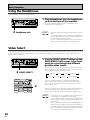
Video Select ............................................................... 58
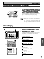
Adjusting the Brightness of the Display .................. 59
Status Display ............................................................ 59
Setting Up the Remote Control to Control Other
Components ............................................................... 60
Recalling Settings Stored in the
Remote Control ..................................................... 60
Programming Signals from Other Remote
Controls (LEARNING Mode) ................................ 62
Locking the Settings .................................................. 63
Using the Remote Control
with Other Components ............................................ 64
DVD and TV operations ........................................ 64
Setting up the DIRECT FUNCTION ........................... 65
Using Other Functions ........................ 66
Recording from Audio/Video Components ............ 66
Speaker System B Setup ........................................... 67
Stereo playback in another room ........................ 67
Bi-amping the front speakers .............................. 67
Bi-wiring your speakers ....................................... 67
Switching A/B Speaker System ........................... 68
Connecting Additional Amplifiers ............................ 69
Pre Out Power Setup ................................................. 70
The PIONEER SR System: Operating other
PIONEER components ............................................... 71
Multi Operations ........................................................ 72
Performing multi operations ............................... 73
System off .................................................................. 74
Using System off .................................................. 75
Editing Remote Control Screen Names
(ITEM MEMO) ............................................................. 76
Editing Buttons Names (KEY LABEL) ....................... 77
Resetting the Main Unit ............................................ 79
Resetting the Remote Control .................................. 79
Techno Tidbits & Problem-solving .... 91
Dolby ........................................................................... 91
Dolby Digital ......................................................... 91
Dolby Pro Logic II ................................................. 92
Dolby Digital Surround EX .................................. 92
MPEG Audio ............................................................... 92
DTS ............................................................................. 93
DTS ........................................................................ 93
DTS-ES .................................................................. 93
DTS Neo:6 ............................................................. 93
DTS 96/24 .............................................................. 93
THX ............................................................................. 93
Speaker Placement Information ............................... 95
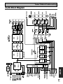
Audio Block Diagram ................................................. 97
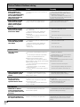
Troubleshooting ......................................................... 98
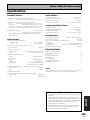
Specifications ........................................................... 103
Advanced Setup .................................. 80
EXPERT
Assigning the Digital Input ....................................... 80
Assigning the Component Video Inputs .................. 81
Expert Setup ............................................................... 82
OSD (On-screen Display) ADJUSTMENT ........... 83
BASS PEAK LEVEL ............................................... 84
DYNAMIC RANGE CONTROL .............................. 85
MULTI CH IN SELECT ........................................... 86
FUNCTION RENAME ............................................ 87
THX Audio Setup ....................................................... 88
THX Ultra2 Subwoofer Setup .............................. 88
Surround Back Speaker Position ......................... 89
Re-Equalization ..................................................... 90
BASIC
Connecting your TV ................................................... 18
Video Converter .................................................... 18
Connecting Video Components ................................ 19
Connecting a DVD, DVD/LD or LD player ........... 19
Connecting VCRs or DVRs ................................... 20
Connecting a Video Component
to the Front Panel ................................................. 20
Connecting Satellite TV (SAT) Components ...... 21
Connecting Analog Audio Components .................. 22
Cassette deck placement ..................................... 23
Connecting to the Multi Channel Analog Inputs
(DVD-A or Super Audio CD compatible player) ... 23
Connecting Digital Audio Components ................... 24
Digital Input Default Settings .............................. 25
Connecting Speakers ................................................. 26
Placing Your Speakers ............................................... 27
Speaker placement ............................................... 27
AC Power Cord ........................................................... 28
AC Outlet [switched 100w max] ............................... 28
Setting Up for Surround Sound ........ 37
Remote Control of Other
Components ........................................ 60
SURROUND SETUP
Home Theater: The Basics ........................................ 10
1) Your Home System .......................................... 10
2) The Source Material ......................................... 10
3) The Listening Modes ........................................ 10
Conclusion ............................................................ 10
1 Hooking Up Your DVD Player & TV ..................... 11
Digital Connections .............................................. 11
2 Speaker Connections ........................................... 12
3 Setting up the Main Unit ...................................... 13
4 Assigning the Digital Inputs ................................ 13
Remote Control .......................................................... 29
Basic Amplifier LCD Screens .................................... 30
Amplifier MAIN Screen ........................................ 30
Amplifier SUB Screen .......................................... 31
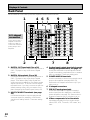
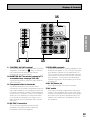
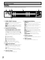
Back Panel .................................................................. 32
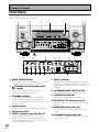
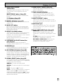
Front Panel ................................................................. 34
Display ........................................................................ 36
PREPARATION
Checking the Supplied Accessories ........................... 6
Preparing the Remote Control .................................... 6
Loading the batteries ............................................. 6
Remote Control Battery Alarm .............................. 6
The Touch Pen & Lock ............................................ 7
Remote Control Cushions ...................................... 7
Operating range of remote control unit ............... 7
Opening the Front Panel ............................................. 7
Setting Up the Remote Control .................................. 8
Remote Control Backlight ........................................... 9
Displays & Controls ............................ 29
GUIDE
QUICK START
PREPARATION
Features ................................................. 3
Table of Contents
4
5
En
En
Table of Contents
Before You Start .................................... 6
Quick Start Guide Part 1 ..................... 10
Quick Start Guide Part 2 ..................... 14
1 Auto Surround Sound Setup ............................... 14
2 Playing a DVD with Surround Sound ................. 17
3 Personalizing Your Sound .................................... 17
Connecting Your Equipment .............. 18
SPEAKER SYSTEMS .................................................. 38
CHANNEL DELAY ...................................................... 41
CHANNEL LEVEL (channel balance) ........................ 42
Acoustic Calibration EQ ............................................ 43
Check the Auto Settings ............................................ 45
Basic Operation ................................... 46
Stereo and Multichannel Playback ........................... 46
Switching the channels used for playback
(LISTENING CH SELECT) ..................................... 47
Switching ANALOG/DIGITAL Signal Input ......... 48
Playback of 96kHz 24 bit sound formats ............. 48
Listening Modes ........................................................ 49
STEREO modes ..................................................... 49
STANDARD modes ............................................... 49
HOME THX modes ............................................... 50
ADVANCED CINEMA modes ................................ 51
ADVANCED CONCERT modes ............................. 52
Adjusting the Effect of Advanced Listening Modes ... 52
Listening with Acoustic Calibration EQ ................... 53
Reducing Noise During Playback
(DIGITAL NR Function) .............................................. 53
Listening in MIDNIGHT Mode ................................... 54
Listening in LOUDNESS Mode ................................. 54
Adjusting Bass and Treble (Tone Control) ............... 55
DVD Audio/MULTI CHANNEL IN Playback .............. 56
DUAL MONO Setting and Playback ......................... 57
Input Attenuator ......................................................... 57
Tape 2 Monitor ........................................................... 57
Using the Headphones .............................................. 58
Video Select ............................................................... 58
Adjusting the Brightness of the Display .................. 59
Status Display ............................................................ 59
Setting Up the Remote Control to Control Other
Components ............................................................... 60
Recalling Settings Stored in the
Remote Control ..................................................... 60
Programming Signals from Other Remote
Controls (LEARNING Mode) ................................ 62
Locking the Settings .................................................. 63
Using the Remote Control
with Other Components ............................................ 64
DVD and TV operations ........................................ 64
Setting up the DIRECT FUNCTION ........................... 65
Using Other Functions ........................ 66
Recording from Audio/Video Components ............ 66
Speaker System B Setup ........................................... 67
Stereo playback in another room ........................ 67
Bi-amping the front speakers .............................. 67
Bi-wiring your speakers ....................................... 67
Switching A/B Speaker System ........................... 68
Connecting Additional Amplifiers ............................ 69
Pre Out Power Setup ................................................. 70
The PIONEER SR System: Operating other
PIONEER components ............................................... 71
Multi Operations ........................................................ 72
Performing multi operations ............................... 73
System off .................................................................. 74
Using System off .................................................. 75
Editing Remote Control Screen Names
(ITEM MEMO) ............................................................. 76
Editing Buttons Names (KEY LABEL) ....................... 77
Resetting the Main Unit ............................................ 79
Resetting the Remote Control .................................. 79
Techno Tidbits & Problem-solving .... 91
Dolby ........................................................................... 91
Dolby Digital ......................................................... 91
Dolby Pro Logic II ................................................. 92
Dolby Digital Surround EX .................................. 92
MPEG Audio ............................................................... 92
DTS ............................................................................. 93
DTS ........................................................................ 93
DTS-ES .................................................................. 93
DTS Neo:6 ............................................................. 93
DTS 96/24 .............................................................. 93
THX ............................................................................. 93
Speaker Placement Information ............................... 95
Audio Block Diagram ................................................. 97
Troubleshooting ......................................................... 98
Specifications ........................................................... 103
Advanced Setup .................................. 80
EXPERT
Assigning the Digital Input ....................................... 80
Assigning the Component Video Inputs .................. 81
Expert Setup ............................................................... 82
OSD (On-screen Display) ADJUSTMENT ........... 83
BASS PEAK LEVEL ............................................... 84
DYNAMIC RANGE CONTROL .............................. 85
MULTI CH IN SELECT ........................................... 86
FUNCTION RENAME ............................................ 87
THX Audio Setup ....................................................... 88
THX Ultra2 Subwoofer Setup .............................. 88
Surround Back Speaker Position ......................... 89
Re-Equalization ..................................................... 90
BASIC
Connecting your TV ................................................... 18
Video Converter .................................................... 18
Connecting Video Components ................................ 19
Connecting a DVD, DVD/LD or LD player ........... 19
Connecting VCRs or DVRs ................................... 20
Connecting a Video Component
to the Front Panel ................................................. 20
Connecting Satellite TV (SAT) Components ...... 21
Connecting Analog Audio Components .................. 22
Cassette deck placement ..................................... 23
Connecting to the Multi Channel Analog Inputs
(DVD-A or Super Audio CD compatible player) ... 23
Connecting Digital Audio Components ................... 24
Digital Input Default Settings .............................. 25
Connecting Speakers ................................................. 26
Placing Your Speakers ............................................... 27
Speaker placement ............................................... 27
AC Power Cord ........................................................... 28
AC Outlet [switched 100w max] ............................... 28
Setting Up for Surround Sound ........ 37
Remote Control of Other
Components ........................................ 60
SURROUND SETUP
Home Theater: The Basics ........................................ 10
1) Your Home System .......................................... 10
2) The Source Material ......................................... 10
3) The Listening Modes ........................................ 10
Conclusion ............................................................ 10
1 Hooking Up Your DVD Player & TV ..................... 11
Digital Connections .............................................. 11
2 Speaker Connections ........................................... 12
3 Setting up the Main Unit ...................................... 13
4 Assigning the Digital Inputs ................................ 13
Remote Control .......................................................... 29
Basic Amplifier LCD Screens .................................... 30
Amplifier MAIN Screen ........................................ 30
Amplifier SUB Screen .......................................... 31
Back Panel .................................................................. 32
Front Panel ................................................................. 34
Display ........................................................................ 36
PREPARATION
Checking the Supplied Accessories ........................... 6
Preparing the Remote Control .................................... 6
Loading the batteries ............................................. 6
Remote Control Battery Alarm .............................. 6
The Touch Pen & Lock ............................................ 7
Remote Control Cushions ...................................... 7
Operating range of remote control unit ............... 7
Opening the Front Panel ............................................. 7
Setting Up the Remote Control .................................. 8
Remote Control Backlight ........................................... 9
Displays & Controls ............................ 29
GUIDE
QUICK START
PREPARATION
Features ................................................. 3
Table of Contents
4
5
En
En
Before You Start
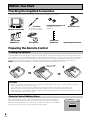
Checking the Supplied Accessories
Please check that you have received all of the following supplied accessories.
U-shaped connectors x 2
(attached to back of
amplifier)
Touch Pen
Remote Control Unit
“AA” IEC LR6
batteries x 4
(attached to the back
of the remote control)
Cushion for
Remote x 4
Microphone
AC power cord
• Operating Instructions
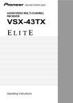
Preparing the Remote Control
Loading the batteries
Load the batteries into the remote control as shown below. The remote control uses a lot of power due to the
LCD display so please use alkaline batteries. Depending on individual use you may have to change the batteries
fairly often but most users should be able to get an average of 1-3 months of battery life. When you notice a
decrease in the operating range or if the alarm sounds (see below), replace all batteries with new ones.
NOTE: After replacing the batteries, the touch panel will need re-adjusting (see p. 8-9).
“AA” IEC LR6
1
2
·
\
3
batteries x 4
·
ª
·
ª
ª
ª
·
\
CAUTION!
Incorrect use of batteries may result in such hazards as leakage and bursting. Observe the following precautions.
• Never use new and old batteries together.
• Insert the plus and minus sides of the batteries properly according to the marks in the battery case.
• Batteries with the same shape may have different voltages. Do not use different batteries together.
• When disposing of used batteries, please comply with governmental regulations or environmental public institution’s
rules that apply in your country or area.
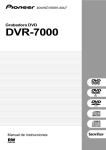
Remote Control Battery Alarm
When the batteries get too weak to operate the remote control properly an
alarm will sound and a warning screen will appear on the remote. Change the
batteries as shown above. This must be done within five minutes of the alarm
sounding or all your remote control settings will be cleared.
6
En
Change Battery !!
SIZE AA, LR6
OK ?
Before You Start
The Touch Pen & Lock
Lock Switch
Touch pen
PREPARATION
The touch pen is located in the back right-hand corner of the remote
control. Take it out by sliding your finger along the bottom right edge
of the remote control and then grasping the pen with thumb and
forefinger.
The lock switch is located in the top right-hand corner on the back of
the remote control. When this switch is set to LOCK you can’t use
the buttons on the remote control. This is helpful to prevent you from
mistakenly pushing a button. For normal use keep the switch set in
USE.
Remote Control Cushions
Apply the cushions to the feet of the remote control as shown in the diagram right.
PREPARATION
Operating range of remote control unit
The area in which you can use the remote control to
operate the VSA-AX10 is fairly large. To use, point the
remote control toward the remote sensor on the front
panel of this unit while within the range shown below.
Remote control may not function properly if:
• There are obstacles between the remote control and
the remote sensor.
• Direct sunlight or fluorescent light is shining onto the
remote sensor.
• The amplifier located near a device emitting infrared
rays.
• Operated simultaneously with another remote control
which uses infrared rays.
30
30
7m
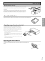
Opening the Front Panel
To open the front panel push gently on the lower third of the panel with your
finger.
7
En
Before You Start
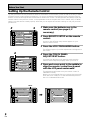
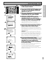
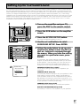
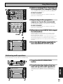
Setting Up the Remote Control
Try and get used to the touch-sensitive nature of the buttons on the remote control as well as the way in which
different screens control different operations. You can move between the different screens with the function
buttons on the left and right and/or certain buttons within each screen. The BACK button will always return the
remote control to the previous screen. In the explanations below complete the TOUCH PANEL ADJUSTMENT
setup to use the remote control properly. After that you can adjust various basic settings to suit your personal
preferences.
3
2
Remote Setup
BACK
REMOTE
SETUP
AMP
DVD/LD
VCR1
/DVR
CD
LCD
COMMANDER
DIRECT FUNCTION
PRESET RECALL
ITEM MEMO
LEARNING
KEY LABEL
CD-R/
TAPE1
TUNER
VIDEO
VCR2
VCR3
SAT
MULTI OPERATION
TV
1 Make sure the batteries are in the
remote control (see page 6, if
necessary).
TV
CONTROL
2 Press REMOTE SETUP on the remote
control.
Access to the different setup modes appear on your
remote control screen.
3 Press the LCD COMMANDER button.
The different types of possible adjustments will appear on
the screen.
4
4 Press the TOUCH PANEL
ADJUSTMENT button.
LCD Commander
BACK
REMOTE
SETUP
AMP
DVD/LD
CD
TOUCH PANEL
ADJUSTMENT
CD-R/
TAPE1
LCD CONTRAST
VCR1
/DVR
VCR2
TUNER
VIDEO
LCD TIMER : 10 SEC
VCR3
TV
SAT
BEEP
OFF
1
2
3
TV
CONTROL
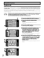
You must first align the touch panel to make sure the
remote control responds properly when you touch it.
5 Press each cross point in the middle to
align the remote control touch panel
with the LCD panel underneath.
This adjustment will make sure your remote control is
calibrated correctly.
When you've touched all four cross points the screen will
show the word "COMPLETE" and automatically return to
the LCD COMMANDER screen.
5
BACK
Touch Panel Adjust
BACK
Touch Panel Adjust
REMOTE
SETUP
AMP
TUNER
TOUCH CROSS POINT
CD-R/
TAPE1
DVD/LD
«
VCR1
/DVR
En
REMOTE
SETUP
CD
CD-R/
TAPE1
DVD/LD
8
BACK
AMP
CD
VCR1
/DVR
TUNER
COMPLETE
VCR2
VIDEO
VCR2
VCR3
SAT
VCR3
SAT
TV
TV
CONTROL
TV
TV
CONTROL
VIDEO
Before You Start
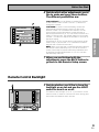
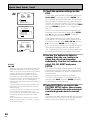
6 Decide which other adjustments you‘d
like to make and press those buttons.
The different possibilities are:
7
LCD Commander
BACK
CD
TOUCH PANEL
ADJUSTMENT
DVD/LD
CD-R/
TAPE1
LCD CONTRAST
VCR1
/DVR
VCR2
TUNER
VIDEO
LCD TIMER : 10 SEC
VCR3
SAT
BEEP
TV
OFF
1
2
3
TV
CONTROL
6
BEEP: When you have sent a command (pushed a button)
the remote control will beep once. You can choose the
sound of the beep from three different possibilities here
by pushing the appropriate button (1,2,3). You can also
turn the beep sound off.
PREPARATION
LCD TIMER: In order to save the battery a timer will
automatically turn the remote control off after a set
amount of time if no commands are entered. You can
choose how long the idle remote control will stay on
before the timer turns it off. You can set this function in a
range of 5-60 seconds. The default setting is 10 seconds.
Use the – /+ buttons to adjust the number of seconds for
the timer setting.
(The REMOTE SETUP screen and its sub-screens are all
fixed to stay on 60 seconds. If no command is entered
they will turn off after 60 seconds.)
REMOTE
SETUP
AMP
PREPARATION
LCD CONTRAST: You can lighten or darken the contrast
on the remote control screen. Use the – /+ buttons to
change the contrast.
7 When you are finished with the
adjustments press the BACK button to
go back to the Remote Setup screen.
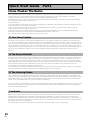
Remote Control Backlight
1
use
LIGHT
REMOTE
SETUP
lock
TV
CONTROL
AMP
CD
FUNCTION
DVD/LD
CD-R/
TAPE1
VCR1
/DVR
TUNER
CH
–
VCR2
VIDEO
VOL
+
VOL
–
VCR3
SAT
TV
TV
CONTROL
1 Decide whether you’d like to have the
backlight on or not and use the LIGHT
switch to turn it on or off.
CH
+
This button turns the light on or off. If you leave it on the
remote screen is easier to see but uses more energy and
thus wears the batteries down quicker.
FUNCTION
MASTER VOLUME
STANDBY/ON
MULTI
SYSTEM
OPERATION
OFF
MUTING
+
ENTER
–
9
En
Quick Start Guide Part1
Home Theater: The Basics
Most consumers are used to using stereo equipment to listen to music but many people are not used to home theater
systems that give you many more options when listening to soundtracks. In fact, home theater is not really
complicated and this little guide should give you an understanding of the basics.
The main reason why it seems so difficult is that there are three different factors involved in home theater and each
will contribute to what kind of sound you get.
These factors are:
1) The equipment you are using for your home theater setup. Particularly important is the number of speakers you are
using. We call this your speaker configuration.
2) The 'source' material you are using. This is the actual product (like a DVD) or broadcast (like cable TV) you are
listening to/watching. We call this the source.
3) The last factor is the listening mode you choose on the VSA-AX10 Amplifier. These are explained below and in
subsequent chapters but most likely the STANDARD (default) setting will be fine.
Let's start with the home theater setup you have in your home.
1) Your Home System
The heart of your system is the VSA-AX10 Amplifier and it is very flexible in getting you theater-like surround sound.
You can use this Amplifier with anywhere from two to seven speakers (front left, front right, center, surround left and
right, and surround back left and right) and a subwoofer to get home theater surround sound. We recommend you use
seven speakers and a subwoofer. If this is not possible follow the instructions in "Auto Surround Setup" in the "Quick
Start Guide" and you will be able to get good surround sound. Also, a DVD player is essential for home theater and you
can also hook up satellite or cable TV tuner to this Amplifier and get a more home theater-like sound from these
sources.
2) The Source Material
DVDs have become the basic source material for home theater because they offer excellent sound and picture quality,
and allow users to enjoy home theater soundtracks with more than two channels of audio. For example, Dolby Pro
Logic plays back four channels (front left, front right, center and a single channel for both surround speakers), Dolby
Digital, MPEG and DTS sources usually have six discrete channels (front left, front right, center, surround left and right
and a channel that powers the subwoofer) of sound. Since the subwoofer channel is only for bass sounds, this
multichannel setup has been named 5.1 channel sound.
It is important you consult the manual that came with your DVD player as well to make sure the player is outputting a
surround soundtrack and all the other settings are appropriate for your home theater.
3) The Listening Modes
This Amplifier has many different listening modes and they are designed to cover all the speaker configurations and
types of sources you might be using. In general, if you follow the recommended advice and have seven speakers and a
subwoofer hooked up, in most cases the STANDARD listening mode is the easiest way to get realistic home theater
sound. This is the default setting so you don't have to do anything.
To listen to music in stereo simply choose the STEREO listening mode. Other possibilities (like listening to a stereo CD
with all seven speakers or taking a stereo source and getting multichannel home theater-like sound) are explained in
listening modes (pages 49–52).
Conclusion
These are the three basic factors that contribute to your home theater sound. The easiest thing is to hook up seven
speakers and a subwoofer and simply play your DVDs with STANDARD 7.1 mode. This will give you realistic and
enjoyable home theater sound. First hook up your equipment, like your DVD player, TV and speakers. Then follow the
instructions to set up your system for surround sound. It is very important you do one of the surround sound setups to
get optimal sound from your Amplifier.
For more details on any of the information presented here check the main section of the manual.
10
En
Quick Start Guide Part1
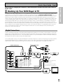
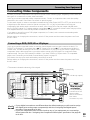
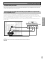
1 Hooking Up Your DVD Player & TV
In order to use Dolby Digital, MPEG or DTS soundtracks you need to hook up your DVD player with digital audio
connections. You can do this by either a coaxial or an optical connection, you don’t need to do both. The
quality of these two types of connections is the same but since some DVD players only have one type of digital
terminal you need to figure out which yours has and hook it up to the appropriate terminal on the Amplifier. In
order to do this you will need the proper cable. For coaxial connections you can use a regular Phono video cord
or the specially-made coaxial cords, they have the same type of plugs. For optical connections you will need a
special optical cable which you can buy at your local stereo store. For more detail on cords/cables see page 25.
You should also hook up your DVD player with analog audio connections. Use regular Phono stereo cords for
these connections. Also hook up the video connection on your DVD player and your TV to this Amplifier. For your
TV it's easiest to use a regular composite Phono video cord, as shown below. It is important that you hook up
your TV (or monitor) in order to see a video image as well as the on screen displays (OSDs) shown by this
Amplifier (for more see page 18).
QUICK START GUIDE
Before making or changing the connections, switch off the power and disconnect the power cord from
the AC outlet.
Digital Connections
Some DVD players have both coaxial and optical terminals, but there is is no need to connect both. If your DVD
player has a coaxial terminal (not a PCM-only output) for the audio out hook it up using this terminal. Follow the
diagram below using DIGITAL IN 1. This is the best scenario, as you will be able to follow the default settings of
this amplifier and won't need to assign the digital inputs.
If your DVD player only has an optical terminal for the audio output you can hook it up using one of the DIGITAL
IN terminals between 4-7 (for example, DIGITAL IN 4). In this case, you will need to assign the digital input
(which means tell the amplifier which input you used for your DVD digital audio). See page 13 for this.
Phono stereo cord
Phono video cord
ANALOG
STEREO
R
L
R
R
L
L
VIDEO
VIDEO
OUT
4
DVD
/LD
IN
MONITOR
OUT
(SAT)
IN
DVD player
IN
IN 3
(CD)
DIGITAL
PCM/2DIGITAL
/DTS/MPEG
2
OUT
(TV)
7
IN
1
PHONO
OUT
IN
CD
IN
(VCR2)
TUNER
IN
POWER AMP
IN
R
IN 1
(DVD
/LD)
IN
(VCR1
/DVR)
4
(SAT)
IN
IN
(DVD
/LD)
(TV)
(For LD)
ASSIGNABLE
2RF
IN
(DVD
/LD)
(DVD
/LD)
(For LD)
ASSIGNABLE
IN
SURROUND
R
L
R
L (Single)
SUB W.
R
R
R
IN
3
Y
Y
PB
PB
FM
75Ω UNBAL
CENTER
AC IN
L
SURROUND
SPEAKERS
R
L
(Single)
OUT
R
VCR3
IN
L (Single)
VIDEO
·
L
SURROUND
BACK
CENTER
IN
ı
S2 VIDEO
(not a PCM-only
output)
PR
COMPONENT VIDEO
R AUDIO L
OUTPUT
R
ª
PR
IN
IN
SURROUND
BACK
L
PR
AM LOOP
ANTENNA
ANTENNA
OUT
OUT
L
MULTI CH INPUT
PB
PR
IN
OUT
SURROUND
PB
2
VCR2
SURROUND
BACK
MONITOR
OUT
IN
OUT
2
REC
IN
PLAY
FRONT
IN 1
IN
IN
PRE OUT
1
(Single)
(CD)
IN 2
TV
IN
SAT
IN
VCR1
/DVR
SUB W.
IN
PLAY
Y
Y
OUT
REC
CD-R/
TAPE1
/MD
OUT
IN 3
L
DIGITAL
AC OUTLET
FRONT
1
IN
CENTER
TAPE2
MONITOR
2RF
L
FRONT
R
OUT
ª
Phono video cord
IN
DVD
/LD
IN
IN
5
MONITOR
OUT
R AUDIO L
AUDIO
(CD-R/
TAPE1
/MD)
6
Å
L
IN
CONTROL
OUT
IN 2
·
MONITOR
OUT
RS-232C
R
You only need to make
one DIGITAL connection.
coaxial cord
optical cord
VIDEO INPUT
11
En
Quick Start Guide Part1
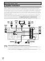
2 Speaker Connections
Home theater is designed to be setup with five, or seven speakers (front left & right; center; surround left &
right; and, optimally, surround back left & right) and a subwoofer, but you can use this amplifier with fewer
speakers. Hook up the speakers you have to the A speaker terminals on the back of the amplifier. If you only
have two speakers hook them up as "FRONT." If you have three hook up the single speaker as "CENTER." Follow
the diagram below in order to hook up all your speakers. A center speaker is very important for watching films
because in digital soundtracks the dialog comes from the center speaker. If you do not have a center speaker
you must tell the amplifier the center channel is off or when you listen to digital soundtracks you won't hear any
dialog. This can be done automatically by following the Auto Surround Sound Setup instructions from page 14 in
this Quick Start Guide.
If possible, use surround back speakers. These speakers are important to take full advantage of all the sound
channels on new, eight channel home theater DVDs. The diagram below also explains how to hook up a
subwoofer which provides realistic bass sounds. For the subwoofer use a mono (single plug) Phono cord and for
the other speakers use regular speaker cords. See pages 95–96 for advice on speaker placement.
Make sure you connect the speaker on the right to the R terminal and the speaker on the left to the L terminal.
Also make sure the positive and negative (+/–) terminals on the amplifier match those on the speakers.
Powered
subwoofer
Front
speaker
(Left)
Center
speaker
Surround
speaker
(Left)
INPUT
DIGITAL
OUT
OUT
OUT
IN
(VCR2)
TUNER
IN
POWER AMP
IN
R
FRONT
R
IN
5
(VCR1
/DVR)
4
(SAT)
IN
IN 3
OUT
PRE OUT
1
R
2RF
IN
(DVD
/LD)
(For LD)
R
SUB W.
En
OUT
OUT
R
R
R
MULTI CH INPUT
IN
2
3
Y
Y
PB
PB
PR
PR
CENTER
AC IN
L
SURROUND
SPEAKERS
R
L
(Single)
ı
·
L
SURROUND
BACK
CENTER
OUT
R
VCR3
R
IN
IN
L (Single)
R AUDIO L
R
ª
COMPONENT VIDEO
SURROUND
BACK
L
PR
IN
IN
L
SURROUND
PB
PR
L (Single)
OUT
Surround back
speaker (Left)
12
IN
VCR2
SURROUND
BACK
IN
PLAY
(DVD
/LD)
ASSIGNABLE
SURROUND
L
Y
MONITOR
OUT
PB
IN
OUT
IN
2
(Single)
AC OUTLET
IN
VCR1
/DVR
SUB W.
IN
PLAY
FRONT
IN 1
1
Y
OUT
REC
CD-R/
TAPE1
/MD
REC
(TV)
IN
SAT
IN
L
OUT
(CD)
IN
TV
IN
CENTER
TAPE2
MONITOR
IN 2
L
ª
FRONT
IN
DVD
/LD
IN
AUDIO
CD
IN
6
IN
MONITOR
OUT
R AUDIO L
IN
(CD-R/
TAPE1
/MD)
Å
Surround
speaker
(Right)
L
IN
CONTROL
PHONO
1
7
·
MONITOR
OUT
PCM/2DIGITAL
/DTS/MPEG
2
memo
Front
speaker
(Right)
TV/monitor
VIDEO
S2 VIDEO
RS-232C
Surround back
speaker (Right)
Ω-16Ω
Ω.
• Please use speakers with a nominal impedance rated 6Ω
• If you only have one surround back speaker hook it up to the left surround back terminal.
• If you use a THX certified subwoofer use the THX INPUT jack on the subwoofer (if your subwoofer
has one) or switch the filter position to THX on your subwoofer.
• When you attached your speaker wire to the speaker terminal make sure that not even one strand
of wire touches the back of the amplifier. If this happens it could short out the amplifier.
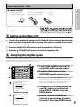
Quick Start Guide Part1
1 Twist exposed wire
strands together tightly.
2 Loosen speaker terminal
and insert exposed wire.
3 Tighten
terminal.
10mm
QUICK START GUIDE
7 Speaker terminals
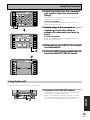
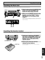
3 Setting up the Main Unit
1 Connect the supplied AC power cord to the back of the main unit and plug the
other end into a wall outlet (don't use any other power cord than the one that
came with this amplifier).
2 Press the POWER ON/OFF button to put the amplifier in ON mode.
3 Press the
STANDBY/ON button to switch the amplifier ON.
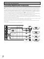
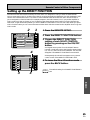
4 Assigning the Digital Inputs
This is only necessary if you did not hook up your DVD player to DIGITAL IN 1 using a coaxial cable, as in
the diagram on p.11, but rather connected it to one of the optical digital inputs. The following example
shows how to assign the DIGITAL IN 3 jack to DVD.
2
1
Amplifier
MAIN
SUB
TONE
BASS/
ATREBLE
CD
VCR1
/DVR
DISPLAY
DIMMER
EFFECT/
CH SEL.
VIDEO
SELECT
STATUS
4
TV
TUNER
VIDEO
VCR2
VCR3
SPEAKER
A/B
SYSTEM
SETUP
1 Turn on the amplifier and your TV,
press AMP on the remote control.
CD-R/
TAPE1
DVD/LD
3
REMOTE
SETUP
AMP
LOUDNESS
INPUT
ATT.
SAT
TAPE 2
MONITOR
SIGNAL
SELECT
TV
CONTROL
System Setup
2 Press the SUB button on the
AMPLIFIER remote control screen.
3 Press the SYSTEM SETUP button.
The SYSTEM SETUP menu appears on your TV (if it
doesn't, refer to page 11 to make sure you have
properly connected the amplifier to your TV).
[ Auto Surround Setup ]
[1. Input Assign ]
[2. Surround Setup]
[3. Expert Setup]
[4. THX Audio Setup]
[Exit]
5
1.Input Assign
[ 1.Digital-In Select ]
[ 2.C' nent Video In ]
[Return]
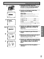
4 Looking at the on-screen display on
your TV, use the 5∞ buttons to
select INPUT ASSIGN. Press the
ENTER button.
5 DIGITAL IN-SELECT should be
selected, if not use the 5∞ buttons
to select it. Press the ENTER button.
13
En
Quick Start Guide Part2
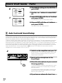
6
1.1. Digital-In
Digital-1
Digital-2
Digital-3
Digital-4
Digital-5
Digital-6
Digital-7
RF IN
Select
[ DVD/LD ]
[ TV ]
[ CD ]
[ SAT ]
[ VCR1 ]
[ VCR2 ]
[ CD-R ]
[ DVD/LD ]
6 The default setting for the DIGITAL-4
jack is SAT.
7 Use the 2 3 buttons to select DVD/
LD.
[Return]
7
1.1. Digital-In
Digital-1
Digital-2
Digital-3
Digital-4
Digital-5
Digital-6
Digital-7
RF IN
[Return]
Select
[ OFF ]
[ TV ]
[ CD ]
[ DVD/LD ]
[ VCR1 ]
[ VCR2 ]
[ CD-R ]
[ DVD/LD ]
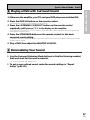
8 Select RETURN with the 5∞ buttons
and press ENTER.
You will return to the SYSTEM SETUP menu.
9 Choose EXIT with the 5∞ buttons
and press ENTER.
The amplifier exits the setup process.
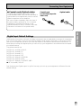
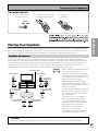
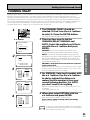
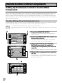
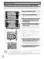
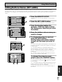
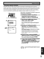
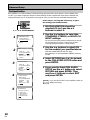
1 Auto Surround Sound Setup
If setting up your surround sound speakers seems like it's going to be an involved task you only need to
use this quick, automatic method to achieve good surround sound. You'll need to hook up the microphone
provided so that the amplifier can hear and judge the distance, size, sound character and sound pressure
level of the speakers and thus know what settings to make.
Follow the step-by-step guide to setting up your surround sound below. This will customize the surround
sound for your listening environment. After you get used to the system it is a good idea to make more
advanced settings as explained in "Expert Setup" (page 82). Also, if you want to personalize your surround
sound setups by making the settings manually go to "Setting up for Surround Sound" (page 37). Make
sure all the components you need, especially speakers, have been properly connected before you do the
steps described here. Use the arrow buttons (5∞) and the ENTER button on the remote control to
navigate the on-screen display (OSD) on your TV.
2
1 Switch on the amplifier and your TV.
Make sure your TV is set to this amplifier as you will
use the on-screen displays (OSDs) on your TV to
follow these instructions.
2 Hook up the microphone to the
Front Panel.
3 Place the microphone at your normal
listening position.
If you have a tripod, attach the microphone to it and
use that to get the mic to ear level at your normal
listening position.
If you don't have a tripod use a table or chair to put
the microphone at the same height as you usually
listen to your system from.
4 If you have a subwoofer turn it on.
14
En
Quick Start Guide Part2
5
MAIN
SUB
TONE
VCR1
/DVR
BASS/
ATREBLE
CD
CD-R/
TAPE1
DISPLAY
DIMMER
VIDEO
SELECT
STATUS
SPEAKER
A/B
EFFECT/
CH SEL.
VCR3
TV
SYSTEM
SETUP
LOUDNESS
INPUT
ATT.
SAT
TAPE 2
MONITOR
SIGNAL
SELECT
TV
CONTROL
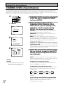
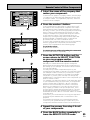
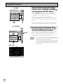
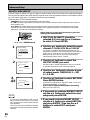
6 Press the SYSTEM SETUP button and
use the on-screen display (OSD) that
appears on your TV.
7 The arrow should be pointing at AUTO
SURROUND SETUP, press ENTER.
System Setup
[ Auto Surround Setup ]
[1. Input Assign]
[2. Surround Setup]
[3. Expert Setup]
[4. THX Audio Setup]
[Exit]
8
TUNER
VIDEO
VCR2
7
5 Press AMP then press the SUB button
on the remote control.
AMP
DVD/LD
6
REMOTE
SETUP
Auto Surround Setup
QUICK START GUIDE
5
Amplifier
8 NORMAL SURROUND should be
selected. (Use the 2 3 buttons to
select it if it isn't.) Use the 5∞ buttons
to select GO NEXT and press ENTER.
For Bi-amp settings choose FRONT BI-AMP 5.1 and
follow the directions from step 3 on page 39.
RETURN brings you back to the system setup menu.
Speaker System Select
[ Normal Surround ]
9 Some auto setup instructions will be
listed, make sure to follow them.
[Go Next]
[Return]
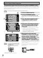
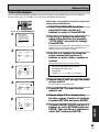
10
Auto Surround Setup
•Connect microphone
•Please be quiet
•Move obstacles away
•If you have a subwoofer
turn power on and
turn volume up
[Start]
[Cancel]
Make sure you have: hooked up the microphone and
moved obstacles to the speakers out of the way. If you
have a subwoofer make sure it is turned on and has the
volume turned up.
\
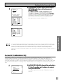
WARNING: The test tones are very loud!! Make sure
there are no infants or small children in the room and
that no one who will be scared, upset or injured by loud
noise is present. You yourself may want to wear earplugs. It is possible to lower the volume of test tones,
but this could result in incorrect speaker settings.
Auto Surround Setup
Please Wait
Caution!!
Test tone is
output loudly.
[Cancel]
\
Try to be as quiet as possible after hitting ENTER. The
test tones may take up to 30 seconds.
Auto Surround Setup
Now Analyzing •••
Environment Check
Ambient Noise
Microphone
Speaker Level
10 If you have followed all setup
instructions and warnings above make
sure that the arrow is pointed to
START and press ENTER. Be prepared
for loud test tones.
[OK]
[OK]
[OK]
The volume automatically increases to 0 dB, then the
system will output some test tones and establish
ambient noise levels, the microphone status, and what
speakers you hooked up.
[Cancel]
\
Check!!
Front
[ YES ]
Center
[ YES ]
Surround
[ YES ]
SurrBack
[ YES X2]
Subwoofer [ YES ]
[OK,Go Next]
[Retry]
[ERR Fix SP.]
[Return to Menu]
15
En
Quick Start Guide Part2
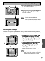
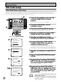
11
Check!!
Front
[ YES ]
Center
[ YES ]
Surround
[ YES ]
SurrBack
[ YES X2]
Subwoofer [ YES ]
[OK,Go Next]
[Retry]
[ERR Fix SP.]
[Return to Menu]
Auto Surround Setup
Now Analyzing •••
Surround Analysis
Speaker Systems
Channel Delay
Channel Level
Acoustic Cal EQ
[OK]
[OK]
[OK]
[OK]
[Cancel]
Speaker Systems Check
” Normal Surround ”
Front
Center
Surround
SurrBack
Subwoofer
[SMALL]
[SMALL]
[SMALL]
[SMALL X2]
[ YES ]
[Next] ( Back/Next )
[Return]
memo
• Make sure the room environment follows the
guidelines displayed on the OSD during auto
setup. If the room environment is not optimal
for auto setup (too much ambient noise,
obstacles blocking the speakers from the
microphone, etc.) the final settings may be
incorrect. Check for household appliances (air
conditioner, fridge, fan, etc.) that may be
affecting the environment and switch them off
if necessary.
• Screens will turn off after three minutes and
the amplifier will automatically exit from the
setup process.
• If you leave CHECK!! or other error message
on the screen for three minutes, or you
choose CANCEL at anytime during the setup,
the settings made up to that point will be
cleared.
• After completing the Auto Surround Sound
Setup, ACOUSTIC CAL EQ ON (ALL CH ADJ)
is set automatically.
16
En
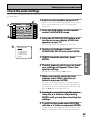
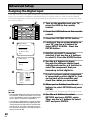
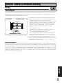
11 Check the speaker settings on the
OSD
If they match your speaker configuration make sure
OK,GO NEXT is selected and press ENTER. The
test tones will be output loudly again. The test tones
may take up to 5 minutes this time. After they have
finished, you see the SPEAKER SYSTEMS CHECK
screen. If you want to view the settings select NEXT
and press ENTER repeatedly. If not, simply go to
step 13.
If they do not match the speaker configuration you
hooked up and you want to try again select RETRY
with 5∞ buttons and press ENTER. Follow the
instructions above from step 10.
If the speaker settings do not match the speaker
configuration you connected and you want to input
the settings manually select ERR=FIX SP with the
5∞ buttons, press ENTER and go to step 12.
If you see an ERR message in the right side column,
there may be a problem with the speaker connection. If selecting RETRY doesn't fix the problem, turn
off the power and check the speaker connections.
12 Use the ∞5 buttons to select a
speaker then the 2 3 buttons to
select the size of each speaker
individually. Use the ∞5 buttons to
select OK, GO NEXT and press
ENTER.
The system will output another series of test tones
to establish the proper channel level, channel delay
and acoustic calibration EQ. Again, be prepared for
loud test tones.
After it has finished, you see the SPEAKER
SYSTEMS CHECK screen. If you want to view the
settings select NEXT and press ENTER repeatedly.
If not, simply go to the next step.
13 Select RETURN to go back to the
SYSTEM SETUP menu, then choose
EXIT to complete the auto surround
sound setup and return to normal
use.
You should now have settings that will give you good
surround sound. The MCACC indicator will light and
the surround sound settings are complete.
Quick Start Guide Part2
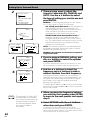
1 Make sure the amplifier, your TV, and your DVD player are switched ON.
2 Press the DVD/LD button on the remote control.
You should see "DVD/LD" in the display on the amplifier.
3 Press the LISTENING CH SELECT button on the remote control
repeatedly until you see "7.1" in the display on the amplifier.
To locate the LISTENING CH SELECT button, press the AMP button then press MAIN to access the
main remote control screen.
QUICK START GUIDE
2 Playing a DVD with Surround Sound
4 Press the STANDARD button on the remote control for the basic
surround sound setting.
If you don't see the STANDARD button, press the AMP button then press MAIN to access the main
remote control screen.
5 Play a DVD then adjust the MASTER VOLUME.
3 Personalizing Your Sound
1 Use the Surround Listening Mode buttons to find the listening mode(s)
that work best for the source material.
For more information see pages 49–52.
2 To get a more refined sound, make the sound settings in "Expert
Setup" (p.82–87).
17
En
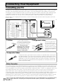
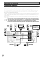
Connecting Your Equipment
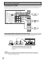
Connecting your TV
Connect your TV to the jacks as shown below. Hook up with either component video, S video, or composite video cords (the quality descends in this order). If you use component video cables to hook up your
DVD player (or other components) then you must hook up your TV with component video cables as well.
In general it is easiest to use one kind of video cord for all your video components (DVD player, TV,
satellite TV receiver, etc.) but you can use different kinds of cables (see "Video Converter" below).
Before making or changing the connections, switch off the power and disconnect the power cord from
the AC outlet.
DIGITAL
OUT
OUT
7
IN
1
PHONO
IN
CD
IN
DVD
/LD
IN
(VCR2)
TUNER
IN
POWER AMP
IN
R
IN
L
FRONT
R
IN
5
(VCR1
/DVR)
4
(SAT)
IN
OUT
L
PRE OUT
1
(TV)
R
IN 1
(DVD
/LD)
(DVD
/LD)
IN
(For LD)
SAT
IN
IN
IN
PLAY
R
SUB W.
L
ASSIGNABLE
R
PR
IN
3
Y
Y
IN
OUT
OUT
PB
COMPONENT VIDEO
IN
L (Single)
OUT
VCR3
L (Single)
S Video
TV/monitor
CENTER
AC
L
SURROUND
R
VIDEO IN
COMPONENT
VIDEO
SPEAKERS
L
ª
(Single)
ı
·
SURROUND
BACK
PB
R
PR
S-VIDEO
L
R
IN
IN
R AUDIO L
R
FM
75Ω UNBAL
PR
CENTER
MULTI CH INPUT
AM LOOP
ANTENNA
ANTENNA
Y
PR
IN
SURROUND
BACK
L
PB
PR
2
VCR2
L
R
PB
IN
OUT
IN
OUT
R
SURROUND
MONITOR
OUT
PB
SURROUND
SURROUND
BACK
FRONT
2RF
IN
2
REC
TAPE2
MONITOR
IN 2
Y
OUT
IN
PLAY
Y
1
VCR1
/DVR
SUB W.
(Single)
(CD)
IN
IN
TV
IN
AC OUTLET
FRONT
CENTER
REC
CD-R/
TAPE1
/MD
OUT
IN 3
MONITOR
OUT
R AUDIO L
AUDIO
(CD-R/
TAPE1
/MD)
ª
Å
L
IN
CONTROL
OUT
6
·
MONITOR
OUT
PCM/2DIGITAL
/DTS/MPEG
2
VIDEO
S2 VIDEO
S video cables produce
clearer picture reproduction
by sending separate signals
SV
IDE
O for the luminance and the
color. These jacks are
labeled by the Japanese
designation "S2" on the
VSA-AX10 but they are
simply S video jacks.
RS-232C
Component video
Y
Green
Blue
Red
PB
PR
The color signal of the
TV is divided into the
luminance (Y) signal and
the color (PB and PR)
signals and then output.
In this way, interference
between the signals is
avoided.
Composite Video
Composite video cords are the most common or standard video cord but also
the lowest quality. The color on the connector is yellow to distinguish it from
regular RCA audio cords which have white and red connectors (see p.22). It is
important to use a true composite video cord and not an audio cord (though
they look exactly the same) because the impedance is different and this will
affect the picture quality.
Video Converter
This unique feature of the VSA-AX10 allows you to hook up your VCR/DVD or any other video player, and/
or your TV tuner with one type of cord to the amplifier while using a different type of cord to hook up the
TV to the amplifier. You can hook them up with either component video, S video, or composite video cords
(the quality descends in this order). The only restriction here is that if you hook up your DVD player, or
other video device, with component video cords (see above), then you must hook up your TV with
component video cords as well. The flexibility afforded by the video converter should make connecting all
of your equipment easier and perhaps, in some cases, give you higher picture quality. This model is
designed for PAL video format. If you use an NTSC source the video converter will not be able to convert
from composite video (in the IN jacks) to S video (in the OUT jacks). All other conversions will be ok.
18
En
memo If you use component video cords to hook up any of you equipment you must assign those
inputs with the "Assigning the Component Video Inputs" procedure. See page 81 to do
this.
Connecting Your Equipment
Connecting Video Components
Connect your video components to the jacks as shown on the following page. Regarding a DVD there are
two types of connections to make, video and audio.
For the audio signal, in order to use digital soundtracks like Dolby Digital, MPEG or DTS you must hook up
a digital input, with either a coaxial or optical cord (see p.25). It is also a good idea to hook up your
components with analog audio connections as well, since some DVDs may not output a digital audio
track. A DVD/LD player or LD player requires a specialized 2 RF connection (shown at the very top of the
first diagram below) to cover the all possible soundtracks on laser discs.
If you want to record from your DVD player composite (or S video) cord connections and analog audio
connections are necessary.
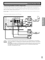
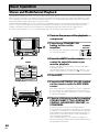
Connecting a DVD, DVD/LD or LD player
Hook up your audio signal with either a coaxial or optical digital cords (you don't need to do both). For
DVD/LD or LD players, if your player has a 2 RF output hook up the 2 RF connection as well (with a
coaxial cord). This will ensure you can use all LDs (see below). If you hook up your DVD/LD player using
component video cable connections you might need to setup your DVD player for component video
output as well. See your DVD manual for details. If you have a DVD-A or Super Audio CD compatible
player, see "Connecting to the Multi Channel Analog Inputs" on page 23.
PREPARATION
Before making or changing the connections, switch off the power and disconnect the power cord from
the AC outlet.
PREPARATION
Hook up your video signal with either component video, S video or composite video cords (the quality
descends in this order). See "Video Converter" on previous page.
You need to hook up your audio with analog connections as well.
Before making or changing the connections, switch off the power and disconnect the power cord from
the AC outlet.
*The arrows indicate the direction of the signal.
2RF OUT
LD player only
(AC-3)(LD)
·
DIGITAL
OUT
OUT
1
OUT
7
IN
PHONO
(VCR2)
TUNER
IN
IN
(VCR1
/DVR)
(SAT)
IN
FRONT
OUT
IN 2
(TV)
IN 1
(DVD
/LD)
IN
(For LD)
ASSIGNABLE
SAT
IN
IN
SURROUND
R
L
R
L (Single)
IN
OUT
SUB W.
R
MULTI CH INPUT
IN
3
Y
Y
PB
PB
3
2R
FM
75Ω UNBAL
CENTER
VIDEO
L
COMPONENT VIDEO
PB
VIDEO
PR
ANALOG
S2 VIDEO
RS-232C
S-VIDEO
(Single)
L
R
IN
DVD/LD player
LD ·player
or ı
SPEAKERS
R
SURROUND
BACK
OUT
IN
AC IN
VIDEO
OUT
COMPO-
SUR- NENT
ROUND
PR
PR
L (Single)
R AUDIO L
AM LOOP
ANTENNA
ANTENNA
Y
VCR3
SURROUND
BACK
R
PR
CENTER
L
L
PB
PR
IN
IN
OUT
R
SURROUND
PB
2
VCR2
SURROUND
BACK
IN
PLAY
IN
OUT
MONITOR
OUT
IN
OUT
2
1
REC
FRONT
2RF
IN
VCR1
/DVR
PRE OUT
IN
PLAY
TAPE2
MONITOR
(DVD
/LD)
TV
IN
OUT
(Single)
(CD)
Y
CENTER
SUB W.
Y
1
L
REC
CD-R/
TAPE1
/MD
OUT
IN 3
IN
L
R
R
4
IN
DVD
/LD
IN
IN
5
FRONT
AUDIO
POWER AMP
IN
AC OUTLET
(not a PCM-only output)
1
MONITOR
OUT
OUT
R AUDIO L
IN
CD
IN
ª
DIGITAL OUT
L
IN
CONTROL
(CD-R/
TAPE1
/MD)
6
Å
MONITOR
OUT
PCM/2DIGITAL
/DTS/MPEG
2
STEREO
L
ª
It is only necessary
L
to make one of the
three possible
R
VIDEO connections
(see "Video
Converter" on p.18).
R
memo • If your digital connections are different than the default settings you will need to assign
the digital jacks to the proper component(s) with the "Assigning the Digital Inputs"
procedure. See page 80 to do this.
• If you use component video cords to hook up any of you equipment you must assign
those inputs with the "Assigning the Component Video Inputs" procedure. See page 81
to do this.
19
En
Connecting Your Equipment
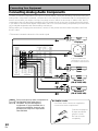
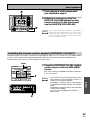
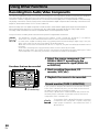
Connecting VCRs or DVRs
Connect the video signal with either S video or composite video cords (see p.18). Use analog audio cords
for the audio signal. For components you want to record into be sure to hook up both the inputs and
outputs and use composite or S video cords for the source players.
DIGITAL
MONITOR
OUT
PCM/2DIGITAL
/DTS/MPEG
2
OUT
OUT
1
OUT
7
IN
(VCR2)
TUNER
IN
POWER AMP
IN
R
5
IN
L
FRONT
R
IN
(VCR1
/DVR)
4
(SAT)
IN
L
OUT
PRE OUT
IN
PLAY
1
(TV)
IN 1
(DVD
/LD)
2RF
SURROUND
R
(DVD
/LD)
(For LD)
ASSIGNABLE
IN
R
R
IN
OUT
OUT
PB
PB
PR
PR
IN
FM
75Ω UNBAL
CENTER
Y
PB
PB
PR
PR
IN
OUT
OUT
AC IN
SURROUND
R
SPEAKERS
OUT
R
R AUDIO L
VIDEO
S2 VIDEO
·
L
L
ROUND
BACK
R
R
R
VIDEO
VIDEO
S-VIDEO
S-VIDEO
IN
ı
(Single)
L
VCR3
IN
ª
AUDIO
(PLAY)
AUDIO
(REC)
LSUR-
SURROUND
BACK
VCR 1/DVR
S-VIDEO
L
3
Y
R
VIDEO
S-VIDEO
COMPONENT VIDEO
IN
L (Single)
MULTI CH INPUT
R
R
VIDEO
L (Single)
R
L
IN
2
VCR2
L
L
IN
MONITOR
OUT
CENTER
SUB W.
SURROUND
R
Y
Y
OUT
AM LOOP
ANTENNA
ANTENNA
IN
L
SURROUND
BACK
IN
PLAY
FRONT
IN
SAT
IN
1
2
REC
TAPE2
MONITOR
IN 2
IN
VCR1
/DVR
SUB W.
(Single)
(CD)
IN
TV
IN
OUT
OUT
IN 3
DVD
/LD
IN
ª
Å
AC OUTLET
L
CENTER
REC
CD-R/
TAPE1
/MD
·
L
FRONT
IN
AUDIO
CD
IN
6
MONITOR
OUT
R AUDIO L
IN
(CD-R/
TAPE1
/MD)
OUT
AUDIO
(PLAY)
IN
CONTROL
PHONO
IN
AUDIO
(REC)
VCR 2
RS-232C
IN
OUT
AUDIO
(REC)
AUDIO
(PLAY)
L
L
R
R
VIDEO
VIDEO
S-VIDEO
S-VIDEO
VCR 3
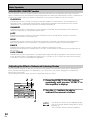
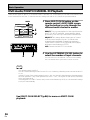
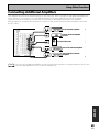
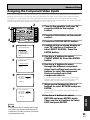
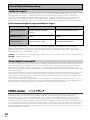
Connecting a Video Component to the Front Panel
Connect a portable DVD player, video game console or any video component to the front panel as show
here. Front video connections are accessed via the front panel input selector as "VIDEO."
EFFECT/CH LEVEL
DIGITAL NR
INPUT ATT
DIGITAL IN
COLOR
BRIGHT
MONITOR
VIDEO-IN/OUT
PHONES
ON/OFF
LISTENING
SELECT
S-VIDEO
VIDEO
VIDEO INPUT
CH SELECT
L
AUDIO
R
AUDIO-IN/OUT
HOLD
DIGITAL OUT (OPTICAL)
Be careful! For portable DVD players you will need a
specialized optical cord (for the audio) that has a mini
optical plug on one end and a regular optical plug on
the other.
memo
20
En
You cannot assign the name of the digital input on the front panel. It will always
appear as "VIDEO" in the amplifier's display. See page 80 for more information on
"Assigning the Digital Inputs".
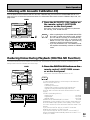
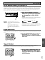
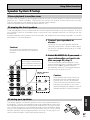
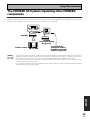
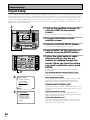
Connecting Your Equipment
Connecting Satellite TV (SAT) Components
Hook up the video signal with either component video, S video, or composite video cords (see p.18).
Before making or changing the connections, switch off the power and disconnect the power cord from
the AC outlet.
*The arrows indicate the direction of the TV signal.
VIDEO
DIGITAL
1
OUT
IN
(VCR2)
TUNER
IN
R
IN
(SAT)
IN
OUT
PRE OUT
IN
PLAY
1
R
TAPE2
MONITOR
IN 2
(TV)
IN 1
(DVD
/LD)
2RF
(DVD
/LD)
R
(For LD)
ASSIGNABLE
R
SUB W.
R
MULTI CH INPUT
PB
PR
PR
IN
2
3
Y
Y
IN
IN
OUT
OUT
PB
PB
PR
PR
IN
IN
OUT
OUT
AM LOOP
ANTENNA
ANTENNA
R
PB
PR
FM
75Ω UNBAL
CENTER
Satellite tuner
AC IN
L
DIGITAL
ANALOG
SUR-STEREO
ROUND
R
DIGITAL
SPEAKERS
L
ı
·
R
(Single)
L
L
SURROUND
BACK
L (Single)
CENTER
R
VCR3
R
IN
IN
L (Single)
R AUDIO L
AC OUTLET
S-VIDEO
ª
COMPONENT VIDEO
SURROUND
BACK
L
OUT
VCR2
L
SURROUND
R
L
SURROUND
BACK
IN
PLAY
FRONT
IN
SURROUND
PB
IN
2
REC
ª
IN
VCR1
/DVR
SUB W.
MONITOR
OUT
IN
OUT
REC
CD-R/
TAPE1
/MD
(Single)
(CD)
Y
SAT
IN
L
Y
1
CENTER
OUT
IN 3
L
R
(VCR1
/DVR)
IN
TV
IN
FRONT
IN
4
IN
DVD
/LD
IN
AUDIO
POWER AMP
IN
Å
VIDEO
OUT
Y
FRONT
R AUDIO L
IN
CD
IN
5
MONITOR
OUT
CONTROL
PHONO
(CD-R/
TAPE1
/MD)
6
L
IN
PREPARATION
OUT
OUT
7
COMPO-·
NENT
MONITOR
OUT
PCM/2DIGITAL
/DTS/MPEG
2
PREPARATION
For the audio signal, in order to use digital soundtracks broadcast you must hook up a digital input. Use
either a coaxial or optical cable, it doesn't matter which (see p.24-25). We recommend hooking up your
audio with analog cables as well (see below).
VIDEO
S2 VIDEO
RS-232C
VIDEO
COMPONENT
VIDEO
OUT
Y
PB
S-VIDEO
PR
TV tuner
ANALOG
DIGITAL
STEREO
DIGITAL
L
R
memo
• If you use component video cords to hook up any of you equipment you must assign
those inputs with the "Assigning the Component Video Inputs" procedure. See page 81
to do this.
• If your digital connections are different than the default settings you will need to assign
the digital jacks to the proper component(s) with the "Assigning the Digital Inputs"
procedure. See page 80 to do this.
21
En
Connecting Your Equipment
Connecting Analog Audio Components
Connect your audio components to the jacks as shown below. These are all analog connections and your
analog audio components (turntable, cassette deck) use these jacks. Remember that for components you
want to record with you need to hook up four plugs (a set of stereo ins and a set of stereo outs), but for
components that only play (like a turntable) you only need to hook up one set of stereo plugs (two plugs).
If you want to record to/from digital components (like a CD-R) to/from analog components you must hook
up your digital equipment with these analog connections.
Before making or changing the connections, switch off the power and disconnect the power cord from
the AC outlet.
*The arrows indicate the direction of the audio signal.
ANALOG
OUTPUT
L
R
CD player
DIGITAL
MONITOR
OUT
PCM/2DIGITAL
/DTS/MPEG
2
OUT
OUT
1
OUT
7
IN
R AUDIO L
IN
(VCR2)
TUNER
CD
IN
(VCR1
/DVR)
REC
POWER AMP
IN
R
IN
(SAT)
IN
R
OUT
CD-R/
TAPE1
/MD
(TV)
(DVD
/LD)
2RF
(DVD
/LD)
IN
R
(For LD)
ASSIGNABLE
SURROUND
R
SUB W.
OUT
Turntable
If your turntable has a
ground wire, connect it to
the SIGNAL GND terminal.
IN
OUT
R
MULTI CH INPUT
ANALOG
OUTPUT
IN
IN
OUT
OUT
L
L (Single)
CENTER
R
VCR3
SURROUND
BACK
L
IN
OUT
VCR2
L
SURROUND
R
L
SURROUND
BACK
IN
PLAY
R
IN
OUT
2
REC
FRONT
IN 1
IN
SAT
IN
VCR1
/DVR
PRE OUT
1
TAPE2
MONITOR
IN 2
L
SUB W.
IN
PLAY
(Single)
(CD)
IN
TV
IN
CENTER
OUT
IN 3
L
FRONT
IN
4
DVD
/LD
IN
AUDIO
CD
IN
5
MONITOR
OUT
CONTROL
PHONO
(CD-R/
TAPE1
/MD)
6
IN
Tuner
IN
IN
L (Single)
R AUDIO L
VIDEO
S2 VIDEO
ANALOG
OUTPUT
(PLAY)
INPUT
(REC)
L
L
R
R
Recorder 1
(CD-R/TAPE/MD)
ANALOG
OUTPUT
(PLAY)
INPUT
(REC)
L
L
R
R
Recorder 2
(CD-R/TAPE/MD)
memo
22
En
Don't hook up any other component to
the PHONO jacks other than a
turntable. It could damage the
equipment. If your turntable has a
phono pre-amplifier (most do not)
please hook it up to an input other
than PHONO.
7 Audio cords
Use Phono audio cords (not supplied) to
connect the audio components.
L
Connect red plugs to
R (right) and white
plugs to L (left).
R
Be sure to insert
completely.
Connecting Your Equipment
Cassette deck placement
Depending on where the cassette deck is placed, during playback of your cassette deck noise may occur
which is caused by leakage flux from the transformer in the amplifier. If you experience noise, move the
cassette deck farther away from the amplifier.
If you have a DVD-A or Super Audio CD compatible player, or are using an external Dolby Digital/DTS
decoder, connect it to the multichannel analog inputs as shown below. Note that if your DVD-A, Super
Audio CD compatible player or decoder which doesn't have surround back outputs, it is possible to create
a 6 or 7 channel environment with the "MULTI CH IN SELECT" feature on page 86.
DIGITAL
MONITOR
OUT
PCM/2DIGITAL
/DTS/MPEG
2
OUT
OUT
1
OUT
7
IN
R AUDIO L
IN
CD
IN
(VCR2)
TUNER
IN
R
L
FRONT
R
(VCR1
/DVR)
IN
4
(SAT)
IN
OUT
IN 2
(TV)
IN 1
(DVD
/LD)
2RF
(DVD
/LD)
PRE OUT
IN
PLAY
1
R
(For LD)
memo
SURROUND
R
SUB W.
OUT
OUT
SUB
WOOFER
SURROUND BACK
L
L
L
IN
IN
R
R
R
OUT
OUT
R
MULTI CH INPUT
IN
IN
OUT
OUT
L (Single)
CENTER
VCR3
SURROUND
BACK
L
CENTER
VCR2
L
SURROUND
R
L
SURROUND
BACK
IN
PLAY
FRONT
ASSIGNABLE
IN
SURROUND
2
REC
R
SAT
IN
FRONT
VCR1
/DVR
SUB W.
TAPE2
MONITOR
IN
L
REC
CD-R/
TAPE1
/MD
(Single)
(CD)
IN
CENTER
OUT
IN 3
IN
TV
IN
ANALOG
POWER AMP
IN
IN
5
DVD
/LD
IN
AUDIO
(CD-R/
TAPE1
/MD)
6
MONITOR
OUT
CONTROL
PHONO
Components equipped with
7.1 (5.1) channel analog output jack
IN
PREPARATION
Before making or changing the connections, switch off the power and disconnect the power cord from
the AC outlet.
PREPARATION
Connecting to the Multi Channel Analog Inputs (DVD-A or Super Audio
CD compatible player)
IN
IN
L (Single)
R AUDIO L
VIDEO
S2 VIDEO
If you use only one surround back input hook up the left one.
23
En
Connecting Your Equipment
Connecting Digital Audio Components
Connect your digital components as shown below. The VSA-AX10 has three coaxial, four optical and one
2 RF inputs for a total of eight digital inputs. In order to use digital soundtracks like Dolby Digital, MPEG
or DTS (among others) you need to make digital audio connections. You can do this by either a coaxial or
an optical connection (you don’t need to do both). The quality of these two types of connections is the
same but since some digital components only have one type of digital terminal, it is a matter of matching
like with like (for example, the coaxial out from the component to coaxial in on the amplifier). A DVD/LD
player or LD player should also be connected to the special 2 RF jack (if the LD has one).
Hook up your digital equipment in accordance with this amplifier's default settings (see next page) unless
you want to, or need to, change them. To do this see "Assigning the Digital Inputs" on p.80.
There are two optical digital out jacks (the CD recorder is connected to one in the diagram below). If you
connect this to the optical input on a digital recorder (currently these include MD, DAT and CD-R) you can
make direct digital recordings with this unit.
We also recommend hooking up your digital components to analog audio jacks (see p.22) in order to make
recordings (some digital sources may be protected against making digital copies).
Before making or changing the connections, switch off the power and disconnect the power cord from
the AC outlet.
*The arrows indicate the direction of the audio signal.
DIGITAL
OUT
OUT
7
IN
1
PHONO
IN
CD
IN
(VCR2)
TUNER
IN
R AUDIO L
R
IN
(SAT)
IN
FRONT
OUT
CD-R/
TAPE1
/MD
(TV)
(DVD
/LD)
2RF
(DVD
/LD)
IN
(For LD)
R
ASSIGNABLE
OUT
DIGITAL
R
SUB W.
L
IN
OUT
OUT
MULTI CH INPUT
IN
IN
OUT
OUT
OUTPUT
L (Single)
CENTER
VCR3
SURROUND
BACK
R
DIGITAL
VCR2
L
SURROUND
L
IN
CD player
SURROUND
SURROUND
BACK
IN
PLAY
R
IN
OUT
2
REC
R
SAT
IN
DIGITAL
IN
IN
OUTPUT
L (Single)
R AUDIO L
VIDEO
En
TV tuner
S2 VIDEO
(not a PCM-only output)
24
CD recorder
VCR1
/DVR
PRE OUT
1
FRONT
IN 1
IN
OUTPUT
SUB W.
IN
PLAY
TAPE2
MONITOR
IN 2
L
REC
(Single)
(CD)
IN
TV
IN
CENTER
OUT
IN 3
L
R
4
DVD
/LD
IN
DIGITAL
POWER AMP
IN
IN
(VCR1
/DVR)
INPUT
(REC)
MONITOR
OUT
AUDIO
(CD-R/
TAPE1
/MD)
5
OUTPUT
(PLAY)
IN
CONTROL
OUT
6
DIGITAL
MONITOR
OUT
PCM/2DIGITAL
/DTS/MPEG
2
DVD player
Connecting Your Equipment
7 Coaxial cords/Optical cables
Coaxial cord
(or standard composite
Optical cable
video cord)
Be sure to insert completely and in the case of
the optical cable, right-side up. If it is inserted
improperly it can break the shutter on the
optical terminal (this won't, however, affect the
connection or insertion of an optical cable).
Unlike analog connections, the jacks for digital connections are not dedicated to one type of component,
they can be used freely. Thus you must tell the amplifier what digital component is connected to which
jack so your components will be in sync with the names on the remote control buttons and the like. To
avoid having to assign the digital inputs you can hook up your equipment in accordance with the amplifier's default settings.
PREPARATION
Digital Input Default Settings
PREPARATION
Commercially available digital audio coaxial
cords (standard video cords can also be used) or
optical cables (not supplied) are used to connect
digital components to this amplifier.
The default settings are:
DIGITAL IN 1 (coaxial): DVD/LD
DIGITAL IN 2 (coaxial): TV
DIGITAL IN 3 (coaxial): CD
DIGITAL IN 4 (optical): SAT
DIGITAL IN 5 (optical): VCR1/DVR
DIGITAL IN 6 (optical): VCR2
DIGITAL IN 7 (optical): CD-R/TAPE 1/MD
2 RF IN (coaxial): DVD/LD
See "Assigning the Digital Inputs" on p.80 if the way you hook up your equipment is different from the
default settings.
25
En
Connecting Your Equipment
Connecting Speakers
We recommend a full complement of seven speakers and a subwoofer as shown here but, naturally,
everyone's home setup will vary. Simply connect the speakers you have in the manner described below.
The VSA-AX10 will work with just two stereo speakers (called "front" speakers in the diagram) but it is
desirable to have at least three speakers (two "front" speakers and a "center" speaker).
One of the latest features of home theater is the use of surround back speakers. These speakers add
even greater realism in movie sound effects and some new discs with soundtracks in Dolby Digital,
MPEG or DTS incorporate these channels.
In general, make sure you connect the speaker on the right to the R terminal and the speaker on the left
to the L terminal. Also make sure the positive and negative (+/–) terminals on the amplifier match those
on the speakers.
Before making or changing the connections, switch off the power and disconnect the power cord from
the AC outlet.
memo
• If you only have one surround back speaker hook it up to the left surround back terminal.
• The VSA-AX10 has two speaker systems, A & B. If you are planning on setting up another
set of speakers (speaker system B), refer to "Speaker System B Setup" on page 67.
• If you use a THX certified subwoofer use the THX INPUT jack on the subwoofer (if your
subwoofer has one) or switch the filter position to THX on your subwoofer.
Powered
subwoofer
Front
speaker
(Left)
INPUT
DIGITAL
OUT
OUT
1
IN
(VCR2)
TUNER
IN
POWER AMP
IN
R
L
FRONT
R
IN
5
(VCR1
/DVR)
4
(SAT)
IN
OUT
L
1
(TV)
IN 1
(DVD
/LD)
R
IN
(DVD
/LD)
(For LD)
ASSIGNABLE
SURROUND
R
R
SUB W.
IN
IN
OUT
OUT
R
MULTI CH INPUT
Surround back
speaker (Left)
PB
PB
PR
PR
IN
OUT
IN
IN
IN
OUT
OUT
IN
2
3
Y
Y
PB
PB
PR
PR
R
CENTER
AC IN
L
SURROUND
SPEAKERS
R
ª
L
(Single)
R
VCR3
L (Single)
VIDEO
·
L
R
IN
IN
ı
SURROUND
BACK
L (Single)
CENTER
R AUDIO L
AC OUTLET
MONITOR
OUT
COMPONENT VIDEO
SURROUND
BACK
L
Y
Y
VCR2
L
SURROUND
R
L
SURROUND
BACK
IN
PLAY
FRONT
2RF
SAT
IN
1
2
REC
TAPE2
MONITOR
IN 2
IN
OUT
PRE OUT
(Single)
(CD)
IN
TV
IN
VCR1
/DVR
SUB W.
IN
PLAY
OUT
IN 3
DVD
/LD
IN
CENTER
REC
CD-R/
TAPE1
/MD
ª
FRONT
IN
AUDIO
CD
IN
6
IN
MONITOR
OUT
R AUDIO L
IN
(CD-R/
TAPE1
/MD)
Å
Surround
speaker
(Right)
L
IN
CONTROL
PHONO
OUT
7
·
MONITOR
OUT
PCM/2DIGITAL
/DTS/MPEG
2
En
Use Speakers
with a nominal
impedance rated
6Ω to 16Ω.
Center
speaker
Surround
speaker
(Left)
26
Front
speaker
(Right)
TV/monitor
S2 VIDEO
RS-232C
Surround back
speaker (Right)
Connecting Your Equipment
7 Speaker terminals
2 Loosen speaker terminal
and insert exposed wire.
1 Twist exposed wire
strands together.
3 Tighten
terminal.
PREPARATION
10mm
Proper speaker placement is essential to realize the best sound from your system. The diagram and tips
given here are just a rough guide, for more information see page 95. Also, it is very important for speaker
placement to read the instructions that come with your speakers so please be sure to do so.
PREPARATION
Placing Your Speakers
Speaker placement
If you have a multiple speaker arrangement the placement of the speakers is extremely important. To
achieve the best possible surround sound, install your speakers as shown below. Make sure all speakers
are installed securely to prevent accidents and improve sound quality. Be sure to consult p.95 and your
speaker manuals for the best placement of the speakers. Some speakers are designed to be floorstanding but others benefit greatly from speaker stands which raise them off the floor.
memo • When installing speakers near the
TV, we recommend using
magnetically shielded speakers to
Front Speaker
prevent possible interference such
(R)
as distortion in the color of the TV
Powered
screen. If you do not have
Subwoofer
magnetically shielded speakers
and notice discoloration of the TV
screen, place the speakers farther
away from the TV.
Surround
• Install the center speaker above or
Speaker (R)
below the TV so that the sound of
the center channel is localized at
the TV screen.
• See page 95 for more detailed
advice on speaker placement.
Surround Back
•
If you have two surround back
Speaker (R)
speakers we recommend placing
them together and the same
distance from your listening
position so you can take
advantage of the ASA feature. For
more details see pages 94-96.
Center Speaker
Front Speaker
(L)
Surround
Speaker (L)
Surround Back
Speaker (L)
CAUTION:
When installing the center speaker on top of the TV be sure to secure it with suitable means.
27
En
Connecting Your Equipment
AC Power Cord
Plug in the power cord first to the receiver and then to the wall outlet after you have finished hooking up
the rest of your equipment.
CAUTION!
• Do not use any other power cord than the one supplied with this unit.
• The amplifier should be disconnected by removing the mains plug from the wall socket when not in
regular use, e.g. when on vacation.
AC Outlet [switched 100 w max]
Power supplied through this outlet is turned on and off by this unit’s STANDBY/ON button. Total electrical
power consumption of connected equipment should not exceed 100 W.
CAUTION!
• Do not connect appliances with high power consumption such as heaters, irons, or television sets to the
AC OUTLET in order to avoid overheating and fire risk. This can cause the amplifier to malfunction.
• DO NOT CONNECT A MONITOR OR TV SET TO THIS UNIT’S AC OUTLET.
28
En
Displays & Controls
Remote Control
These pages describe the buttons on the remote control. Since the screen on this LCD remote control changes
when you select a different function, explanations of buttons for controlling other components/functions can be
found in the sections for those components/functions.
2
3
4
5
7
6
use
REMOTE
SETUP
LIGHT
lock
TV
CONTROL
AMP
CD
FUNCTION
DVD/LD
CD-R/
TAPE1
VCR1
/DVR
TUNER
VCR2
VIDEO
VCR3
SAT
TV
TV
CONTROL
CH
+
CH
–
VOL
+
VOL
–
FUNCTION
8
9
MULTI
SYSTEM
OPERATION
OFF
MUTING
+
ENTER
–
!
memo
1
~ = -
0
PREPARATION
MASTER VOLUME
STANDBY/ON
PREPARATION
1
To turn on the remote control touch it anywhere on the screen
STANDBY/ON button
Press to turn power of the amplifier on or to
STANDBY (off).
2 LIGHT button
Use to turn on and off the backlight on the remote
control screen.
3 AMP button
Press to switch the remote control into amplifier
mode or to get amplifier screens.
4 Function buttons
These buttons are the basic controls that switch
the mode of the amplifier and the remote control,
which allows you to control your other
components.
5 Remote control screen (see p.30-31)
6 REMOTE SETUP button
Use to customize the remote control functions
and the remote control itself. (See “Setting Up
Remote Control of Other Components“ starting
on p.60)
7 LOCK switch
Use to lock the remote control so it doesn't turn
on by accident. For normal use keep it set in USE.
8 TV CONTROL buttons
The following buttons are used to control the TV
only and can be used once they are preset to
control your TV.
STANDBY/ON : Press to turn the power of the
TV on/off.
INPUT : Press to select the input source for the
TV.
CH +/– : Use these buttons to change the channel
of the TV.
VOL +/– : Press to control the volume of the TV.
9 INPUT button
Press to select a source. The button will cycle
through all the possible sources.
0 MASTER VOLUME button
Use to raise or lower the volume of the amplifier.
- MUTING button
Press to mute or restore the volume.
= SYSTEM OFF button (see p.75)
This button turns off components in two ways.
First, when pressed it will turn off all PIONEER
components. Secondly, any component that has
programmed into the SYSTEM OFF settings will
be turned off.
For example : If you programmed power off in
the SYSTEM OFF settings for your TV and VCR,
pressing the SYSTEM OFF button will turn off
these components even if they are not PIONEER
products.
~ MULTI OPERATION button
Use this button to start the MULTI OPERATION
mode. See p.73 for how to program and use the
MULTI OPERATION mode.
! 5˜∞˜2˜3˜ENTER buttons
These buttons can be used for a variety of
operations. In the SYSTEM SETUP menu, the
5˜∞ buttons can be used to adjust CHANNEL
DELAY or CHANNEL LEVEL.
The 5˜∞ buttons, pressed simultaneously, can
be use to lock or unlock a setting (see p.63).
These buttons are also used to control the DVD
menu for the DVD remote control screen. Also, in
TUNER mode they can select station and
frequency.
29
En
Displays & Controls
Basic Amplifier LCD Screens
Amplifier MAIN Screen
1
Amplifier
MAIN
SUB
LISTENING MODE
(DVD-A
/SACD)
SURROUND
8
STEREO
/DIRECT
MIDNIGHT
2
THX
STANDARD
MULTI CH
IN
ADVANCED
CINEMA
ADVANCED
CONCERT
LISTENING
CH SEL.
DIGITAL
NR
Press this button to select the MAIN amplifier
screen (above) when the remote control is on the
SUB amplifier screen.
2 MIDNIGHT button (See p.54)
Switches the MIDNIGHT listening mode on or off
(for all modes except THX).
3 DIGITAL NR button (See p.53)
Switches the DIGITAL NR on or off (for all modes
except THX).
4 LISTENING MODE buttons (See p.49-52)
STEREO/DIRECT: Switches the amplifier into
STEREO mode if it was in a different listening
mode or toggles between DIRECT and STEREO
mode.
THX: Press to put the amplifier into HOME THX
listening mode.
STANDARD: Press to put the amplifier into
STANDARD listening mode.
ADVANCED CINEMA: Press to put the amplifier into ADVANCED CINEMA listening mode.
ADVANCED CONCERT: Press to put the
amplifier into ADVANCED CONCERT listening
mode.
30
En
ACOUSTIC
CAL.
3 45 6
1 Amplifier MAIN button
8
7
5 MULTI CH IN button (See p.56)
Use this button to select the component (for
example, a DVD-Audio player) you have hooked
up to the MULTI CH INPUT terminals.
6 LISTENING CH SEL. button (See p.47)
Use this button to select a listening channel (5.1,
7.1, or AUTO).
7 ACOUSTIC CAL. button (see p.53)
Press to switch on/off the acoustic calibration EQ.
8 DIRECT FUNCTION on/off indicator (See
p.65)
These dots indicate whether the DIRECT
FUNCTION is on or off for the function (DVD/LD,
CD, etc.) they point to.
Displays & Controls
Amplifier SUB Screen
1
BASS/
TREBLE
2
DISPLAY
DIMMER
VIDEO
SELECT
3
STATUS
SPEAKER
A/B
4
SYSTEM
SETUP
EFFECT/
CH SEL.
LOUDNESS
INPUT
ATT.
0
TAPE 2
MONITOR
SIGNAL
SELECT
9
5 6 7
1 Amplifier SUB button
Press this button to select the SUB amplifier
screen (above) when the remote control is on the
main amplifier screen.
2 DISPLAY DIMMER button (See p.59)
Use to adjust the brightness of the amplifier's
display.
3 STATUS button (See p.59)
Use to display the present mode of the
amplifier and other selected settings.
4 SYSTEM SETUP button
Use for all system setups, including the speaker
and sound systems. For more information see
“Setting up for Surround Sound“ starting on p.37.
5 VIDEO SELECT button
Use to toggle between the different video input
possibilities.
6 SPEAKER A/B button (See p.68)
Use to select the speaker system. A is the
primary setting. The button cycles through the
speaker systems as follows: A]B]A&B]off.
Different conditions apply when bi-amping the
speakers. For this case refer to page 67.
7 LOUDNESS button (See p.54)
Switches the LOUDNESS mode on or off (for all
modes except THX).
8 TAPE 2 MONITOR button
Selects the tape deck (or MD recorder, etc.)
connected to the TAPE 2 MONITOR inputs/
outputs. Allows monitoring of a recording as it's
being made.
SUB
8
9 SIGNAL SELECT button (See p.48)
PREPARATION
TONE
MAIN
PREPARATION
Amplifier
Press SIGNAL SELECT repeatedly to select one of
the following:
ANALOG : To select an analog signal.
DIGITAL : To select a digital signal
2 RF : To select an 2 RF signal
AUTO : This is the default. If there are analog,
digital and 2 RF signals input, the amplifier
automatically selects the 2 RF signal. If there are
analog and digital signals input the digital will be
selected.
0 INPUT ATT. button
Use to lower the input level of an analog signal
that is too powerful, thus causing the amplifier to
distort. In this case the overload (OVER) indicator
will be flashing furiously.
- TONE control/EFFECT CH SEL. buttons
TONE button
This button has two functions. Firstly, it
switches between TONE on and TONE BYPASS, which bypasses the tone circuitry.
Secondly, you need to press the button before
using the BASS & TREBLE (+/–) buttons (see
p.55).
EFFECT/CH SEL. button
Switches the tone adjust controls between the
front, center, surround and surround back
speakers. You can then use the + and – buttons
to adjust the sound (see p.52).
While in Advanced mode, you can also adjust
the effect level.
31
En
Displays & Controls
Back Panel
All the terminals on the back panel are explained and/or referenced here.
1
4 6 5
9
10
DIGITAL
MONITOR
OUT
PCM/2DIGITAL
/DTS/MPEG
2
OUT
OUT
7
6: U-shaped
connectors
IN
1
OUT
IN
6
(VCR2)
R AUDIO L
Don't remove the Ushaped connectors
unless you plan to
connect an external
power amp to this
amplifier.
CD
IN
POWER AMP
IN
R
IN
(VCR1
/DVR)
(SAT)
IN
IN 3
TUNER
IN
OUT
PRE OUT
IN
PLAY
1
R
2RF
IN
(DVD
/LD)
R
SUB W.
R
L
3
Use these terminals to output the signal from a
DVD, CD player or any other kind of digital
player.
2 DIGITAL IN terminals (See p.24)
Use these terminals to input the signal from a
DVD, CD player or any other kind of digital
player. To be able to play Dolby Digital and
other surround soundtracks you need to make
digital connections. To do this use the digital
terminals here. If you don't connect as per the
default settings (see p.26) you need to complete "Assigning the Digital Inputs" (see p.81).
3 MULTI CH INPUT terminals (see page
23)
Use these terminals to input a multichannel
surround signal (for example, a DVD-Audio
signal) in an analog fashion. These are analog
jacks.
En
IN
OUT
OUT
IN
IN
OUT
OUT
R
IN
IN
OUT
OUT
L (Single)
CENTER
VCR3
IN
IN
L (Single)
R AUDIO L
MULTI CH INPUT
1 DIGITAL OUT terminals (See p.24)
32
SAT
IN
VCR2
SURROUND
BACK
R
ASSIGNABLE
L
L
SURROUND
(For LD)
2
SURROUND
SURROUND
BACK
IN
PLAY
(DVD
/LD)
IN
2
REC
FRONT
IN 1
TV
IN
VCR1
/DVR
SUB W.
OUT
(TV)
L
REC
CD-R/
TAPE1
/MD
(Single)
(CD)
IN
CENTER
TAPE2
MONITOR
IN 2
L
FRONT
R
4
DVD
/LD
IN
AUDIO
IN
5
MONITOR
OUT
CONTROL
PHONO
(CD-R/
TAPE1
/MD)
IN
7
VIDEO
S2 VIDEO
8
4 Analog input/output terminals (connect
analog components here, see page 22)
Use these terminals to input/output the audio
signal from analog components (like a cassette
deck or turntable). These are analog jacks.
5 POWER AMP IN terminals
Use this terminal to connect an external control
amp to this amplifier (see page 69 & 70).
Remove the U-shaped connectors only if you
plan to do so.
6 U-shaped connectors
7 PRE OUT analog terminals
Use these terminals to output the (analog)
audio signal from this amplifier to a different
power amplifier (see page 70). Remove the Ushaped connectors only if you plan to do so.
8 Video components in/out terminals
Input/output signals from you video components (DVD, VCR, TV tuners, SAT tuners, etc.)
here.
Displays & Controls
15
Å
PREPARATION
·
ª
L
AC OUTLET
FRONT
IN
1
Y
Y
R
MONITOR
OUT
PB
PR
PR
IN
IN
2
3
Y
Y
PB
PB
CENTER
AC IN
L
SURROUND
SPEAKERS
R
ª
PR
ı
·
PR
COMPONENT VIDEO
L
(Single)
L
SURROUND
BACK
R
PREPARATION
PB
R
RS-232C
11
12
13
9 CONTROL IN/OUT terminal
You can use this jack to hook up other PIONEER
equipment, that bears the Î mark, so that you
can control them all pointing the remote
control(s) at one remote sensor.
10 MONITOR OUT terminals (connect a TV
or monitor here, see page 11 & 18)
Use these terminals to output a video signal to
a TV or monitor.
11 Component video in terminals
Use these terminals to hook up the video
connections of your video components with this
high quality method. Your components will have
to have the terminals as well to take advantage
of this kind of connection. See p.19 for more on
setting up your amplifier for component video.
If you use these terminals you need to complete "Assigning the Component Video Inputs"
(see p.81).
14
13 SPEAKER terminals
Use these terminals to connect speakers to the
amplifier (see pages 12, 26, 67 & 68). There are
two speaker systems on this amplifier A & B.
The A system is the one that handles surround
sound and is fed by the surround and surround
back speakers. If you want to use alternative
speaker connections like bi-amping or bi-wiring
see page 67.
14 AC IN (Power In)
Hook up the power cord to this terminal.
15 AC outlet
Hook up an external component to the power
supply of this amplifier. Only do this with audio
or video components being used in this system
and never hook up heavy equipment (like TVs,
heaters, air conditioners, refrigerators, etc.) to
this amplifier.
12 RS-232C Connection
This is a future-oriented port that has the
possibility on inputting and/or outputting
information to/from the amplifier.
33
En
Displays & Controls
Front Panel
All the controls on the front panel are explained and/or referenced here. To open the front panel push
gently on the lower third of the panel.
23
1
4
5
8 9
7
6
AUDIO VIDEO MULTI-CHANNEL AMPLIFIER
VSA-AX10
LISTENING MODE SELECTOR
PUSH ENTER
STANDBY/ON
STANDBY
VIDEO
OFF
DVD/LD
ON
TV/DVD
SAT
VIDEO
AUDIO
VCR1/DVR
VCR2
VCR3
CD
CD-R/
TAPE1/MD
TUNER
PHONO
MULTI CH
INPUT
INPUT SELECTOR
0
MASTER VOLUME
-
%
~
=
^
&
*
(
1 INPUT SELECTOR dial
Turn to select a source component. The input
indicators show the current component.
2
STANDBY/ON button–power ON/
OFF button
Press to switch the amplifier ON or into
STANDBY mode or to switch OFF.
3 STANDBY indicator
Lights when the amplifier is in STANDBY
mode. (Please note that this amplifier consumes a small amount of power [0.65 W] in the
standby mode.)
4 Remote sensor
Receives the signals from the remote control.
5 Display (See p.36)
6 MCACC indicator (see p.16, step 13)
Lights when the ACOUSTIC CAL EQ is on.
(After the Auto Surround Sound Setup has
been completed the ACOUSTIC CAL EQ is set
on and this display will light.)
34
En
!
)
_
@
#
$
+
7 INPUT indicators
Shows which source component is selected.
The MULTI CH INPUT indicator lights when a
component connected to MULTI CH INPUT is
selected.
8 LISTENING MODE SELECTOR dial
Turn and push to select a listening mode.
9 MASTER VOLUME dial
Adjusts the overall amplifier volume.
10 ACOUSTIC CAL. button (see p.53)
Use to switch on and off the Acoustic Calibration EQ.
11 MIDNIGHT button (see p.54)
Use to switch the amplifier into MIDNIGHT
mode.
12 LOUDNESS button (See p.54)
Switches the LOUDNESS mode on or off (for all
modes except THX).
Displays & Controls
13 TONE control buttons
TONE button
This button switches between TONE ON and
TONE BYPASS, which bypasses the tone
circuitry.
Use to select whether the bass or treble will be
adjusted.
(–/+) buttons (See p.55)
Use to adjust the frequencies.
14 DIGITAL NR button (see p.53)
Switches the DIGITAL NR on or off (cannot be
used in THX).
Use to lower the input level of an analog signal
that is too powerful, thus causing the amplifier to
distort. In this case the overload (OVER) indicator
will be flashing furiously.
16 EFFECT/CH LEVEL buttons
Switches the tone adjust controls between the
front, center, surround and surround back
speakers. You can then use the + and – buttons
to adjust the sound (see p.52).
While in Advanced mode, you can also adjust
the effect level.
17 LISTENING CH SELECT button (See
p.47, 56 & 57)
22 TAPE 2 MONITOR button
Selects the tape deck (MD recorder, etc.)
connected to the TAPE 2 MONITOR inputs/
outputs. Allows monitoring of a recording as
it's being made.
23 MULTI CH INPUT button
Selects the component (for example, a DVDAudio player) you have hooked up to the MULTI
CH INPUT terminals.
24 SETUP MIC jack
Plug in the setup mic here. This is very important for setting up your system to get proper
surround sound.
25 Front VIDEO INPUT jacks (See p.20)
DIGITAL IN : digital input for connecting a
game console, portable DVD player, video
camera (etc.), that has an optical digital connection.
PREPARATION
15 INPUT ATT. button
Switches the amplifier between the various
types of video input.
PREPARATION
BASS/TREBLE button (See p.55)
21 VIDEO SELECT button (See p.58)
S VIDEO : Video input for connecting a video
camera (etc.), that has an S video out.
RCA VIDEO / AUDIO (L/R) : Video input for
connecting a video camera, etc. that has
standard RCA video/audio outputs.
Use this button to select the number of
channels used for playback (5.1, 7.1, or AUTO).
18 PHONES jack
Connect headphones for private listening (no
sound will be heard through the speakers).
19 SP SYSTEM A/B button (See p.68)
—
_
—
Use to select the speaker system. A is the
primary setting. The button cycles through the
speaker systems as follows: A]B]A&B]off.
Different conditions apply when bi-amping the
speakers. For this case refer to page 67.
20 SIGNAL SELECT button (see p.48)
Use to select the type of signal being input into
the amplifier. Press SIGNAL SELECT repeatedly
to select one of the following:
ANALOG – To select an analog signal.
DIGITAL – To select an optical or coaxial digital
signal.
2 RF – To select an 2 RF signal.
AUTO – This is the default setting. If there are
analog, digital and 2 RF signals input, the
amplifier automatically selects the 2 RF signal.
If there are analog and digital signals input the
digital will be selected.
35
En
Displays & Controls
Display
All the display information is explained and/or referenced here.
1
2
34
SIGNAL
L
C
R
AUTO
LS
S
RS
RF
DIGITAL
ANALOG
5
6
DIGITAL
LFE
OVER ATT
SP 3 AB
DISC MTRX
PRO LOGIC
TAPE 2
Neo :6 MPEG
RDS
E ON RF ATT
2ch PLAYBACK
87
1 SIGNAL SELECT indicators
2 DIGITAL: Lights when a Dolby Digital signal is
ANALOG: Lights when an analog signal is
selected.
DIGITAL: Lights when a digital signal is selected.
2RF: Lights when an 2 RF signal is selected.
AUTO: Lights when the amplifier is set to select
the input signal automatically.
detected.
DTS: Lights when a DTS signal is detected.
MPEG: Lights when an MPEG signal is detected.
THX: Lights when the HOME THX mode is
selected.
EX: Lights during Surround EX matrix processing.
ES: Lights when a decoding DTS ES audio.
DISC: Lights during DTS ES discrete processing.
MTRX: Lights during DTS ES matrix processing.
2 PRO LOGIC II: Lights during Dolby Pro Logic II
processing.
NEO:6: Lights during NEO:6 processing.
2CH PLAYBACK Lights during two-channel
playback.
2 Program Format indicators
For Dolby Digital, MPEG or DTS sources :
These indicators change according to which
channels are active in the source. When all
three LS (left surround), S (surround) and RS
(right surround) light at the same time it means
a source with a 6.1ch playback flag is being
used.
L – Left front channel
C – Center channel
R – Right front channel
LS – Left surround channel
S – Surround channel (mono)
RS – Right surround channel
LFE – Low frequency effects channel
3 ((( ))) – Lights when LFE signal is input
4 Analog level indicators
OVER – This lights if the signal is in danger of
distorting for analog source signals. Press
INPUT ATT on the front panel to lower the
signal level.
ATT – Lights when INPUT ATT is used to
reduce the level of the analog source signal.
5 Character display
Shows current mode, status, etc.
36
En
6 Digital format indicators
Light to indicate the input signal you selected.
7 Speaker indicators
Light to indicate the current speaker system, A
and/or B.
8 TAPE 2 indicator
Lights when the TAPE 2 monitor is on.
Setting Up for Surround Sound
To ensure the best possible surround sound, complete the following setup operations. Some of these may be
the same (and take precedence over) the settings you made in the Quick Start Guide. If you think the ones you
made at that time were adequate move on to the next setting here. You only need to make these settings once
(unless you change the placement of your current speaker system or add new speakers, etc.). These setup
operations use on-screen displays (OSDs) on your TV to display the settings and choices so be sure your TV and
amplifier are properly hooked up and that your TV is set to this amplifier. Also, make sure the microphone that
hooks up to the front panel of the amplifier is connected as in some cases you may need to use it. For more
information on the microphone hookup see pages 14-16.
1
2
use
Amplifier
LIGHT
MAIN
REMOTE
SETUP
SUB
lock
TV
CONTROL
AMP
LISTENING MODE
VCR1
/DVR
STEREO
/DIRECT
VCR2
FUNCTION
CD-R/
TAPE1
THX
STANDARD
MULTI CH
IN
ADVANCED
CINEMA
ADVANCED
CONCERT
LISTENING
CH SEL.
VCR3
MIDNIGHT
TV
ACOUSTIC
CAL.
DIGITAL
NR
+
CH
TUNER
CH
–
VIDEO
VOL
+
SAT
VOL
–
TV
CONTROL
FUNCTION
MASTER VOLUME
STANDBY/ON
Make sure your TV is connected and set to the amplifier.
CD
(DVD-A
/SACD)
SURROUND
DVD/LD
1 Turn on the amplifier and your TV,
press the AMP on the remote control.
MULTI
SYSTEM
OPERATION
OFF
3 Press the SYSTEM SETUP button.
+
MUTING
2 Press the SUB button on the amplifier
screen.
ENTER
The menu possibilities appear on your TV.
–
4 Use the 5∞ and buttons to select
SURROUND SETUP. Press ENTER.
Amplifier
MAIN
SUB
REMOTE
SETUP
AMP
BASS/
ATREBLE
DISPLAY
DIMMER
VIDEO
SELECT
STATUS
SPEAKER
A/B
CD
CD-R/
TAPE1
DVD/LD
VCR1
/DVR
EFFECT/
CH SEL.
VIDEO
VCR2
VCR3
TV
SYSTEM
SETUP
LOUDNESS
INPUT
ATT.
SAT
TAPE 2
MONITOR
SIGNAL
SELECT
TV
CONTROL
3
4
TUNER
System Setup
[Auto Surround Setup]
[1. Input Assign ]
[2. Surround Setup ]
[3. Expert Setup ]
[4. THX Audio Setup ]
[Exit]
5 Follow the order below to set up your
speakers for better sound. Use the 5∞
and 2 3 buttons to navigate through
the menus. When you have the setting
you want in a particular menu, press
ENTER.
In each mode, the current settings are displayed. We
suggest you adjust all these settings when you first hook
up the amplifier. That gets them out of the way and you
won't need to return to this setting mode unless you
change your home setup by adding new speakers (etc.).
SURROUND SETUP
TONE
SPEAKER SYSTEMS (See p.38-40)
Use to specify the type and number of speakers you
connected.
CHANNEL DELAY (See p.41)
You must add distance settings to all your speakers for the
most realistic surround sound. Adding a slight delay to
some speakers enhances sound separation and is particularly important for achieving a surround sound effect. You
need to figure out the distance from your listening position
to your speakers to add the proper delay.
CHANNEL LEVEL (See p.42-43)
Use to balance the volumes of your different speakers.
ACOUSTIC CALIBRATION (See p.43-44)
This setting is a kind of room equalizer for your speakers.
37
En
Setting Up for Surround Sound
SPEAKER SYSTEMS
The following steps show you how to select the correct setup for the type and number of speakers you
connected. Most importantly, you need to decide how to route the sound for all the speakers you connected. To
do this select the size of the front, center, surround and surround back speakers (if you hooked them up). It is
important to make these settings as accurately as possible or, in some cases, you may not get the full
soundtrack from a disc. The auto setup from the microphone may not properly assess the size of your speakers
if there is background noise, from an air conditioner or refrigerator, for example. If necessary try different
possible settings manually.
Use the information below to complete the steps that follow and set up the amplifier to match the speakers you
have hooked up. Make sure the microphone is hooked up to the front panel and in the appropriate position
before starting. See page 14 for more information on setting up the microphone.
FRONT (default setting is SMALL)
Select SMALL to send bass frequencies to the subwoofer. Select LARGE if your speakers will reproduce bass
frequencies effectively or if you did not connect a subwoofer. (If you select SMALL for the front speakers the
subwoofer will automatically be switched YES. Also, the center and surround speakers cannot be set to
LARGE if the front speakers are set to SMALL. In this case, all bass frequencies are sent to the subwoofer.)
CENTER (default setting is SMALL)
• Select LARGE if your speaker will reproduce bass frequencies effectively.
• Select SMALL to send bass frequencies to the other speakers or subwoofer.
• If you did not connect a center speaker, choose NO. In this case, the center channel is output from the
front speakers.
SURROUND (default setting is SMALL)
• Select LARGE if your speakers will reproduce bass frequencies effectively.
• Select SMALL to send bass frequencies to the other speakers or subwoofer.
• If you did not connect surround speakers choose NO. In this case, the sound of the surround channels is
output from the front and center speakers.
• Remember, If you select SMALL for the front speakers, the surround and surround back speakers can only
be set to SMALL.
SURROUND BACK (default setting is SMALL X2)
• Select the number of surround back speakers you have. You can choose one speaker, two, or none.
• If you select one, make sure that speaker if hooked up to the left surround back terminal.
• Select LARGE if your speakers will reproduce bass frequencies effectively.
• Select SMALL to send bass frequencies to the other speakers or subwoofer.
• If you did not connect surround back speakers choose NO.
• If the front speakers or the surround speakers are set to SMALL, the surround back speakers will automatically be set to SMALL.
• If you choose THX in step 2 then the surround back speakers can only be set to SMALL X1 or X2 (or NO).
SUBWOOFER (default setting is YES)
• Leave it selected if you connected a subwoofer.
• If you selected SMALL for the front speakers the subwoofer will automatically be set to on (you won’t be
able to choose NO or PLUS).
• If you did not connect a subwoofer choose NO. In this case, the bass frequencies are output from the front
or surround speakers.
• Choose the PLUS setting if you want stronger reproduction of deep bass sounds.
• If you select PLUS the bass frequencies that would normally come out the front and center speakers are all
routed to the subwoofer.
38
En
Setting Up for Surround Sound
1
STANDBY/O
ENTER
1 SPEAKER SYSTEMS should be
selected. If it isn’t use the 5∞ buttons
to select it. Press the ENTER button.
The setup possibilities appear on your TV.
5˜∞ buttons
2.Surround Setup
[ Check ]
[
[
[
[
1.Speaker Systems ]
2.Channel Delay ]
3.Channel Level ]
4.Acoustic Cal EQ ]
[Return]
2
2.1. Speaker Systems
[Manual Free]
[Manual THX]
(all small)
[Auto]
[Return]
2.1. Speaker Systems
Manual Free
Speaker System Select
[ Normal Surround ]
(
5
Next)
For MANUAL FREE, select it and press ENTER. Then go
to step 3.
For MANUAL THX, select it and press ENTER. Then go
to step 3.
For AUTO, select it and press ENTER. Be prepared for
loud test tones and make sure the room is free of ambient
noise (see memo page 16). When you see OK on the OSD
the setup is finished. Go to step 9.
3 Use the 2 3 buttons to select either
NORMAL SURROUND or FRONT BIAMP (5.1).
NORMAL SURROUND: For normal home theater use
FRONT BI-AMP (5.1): Settings for bi-amp (see p.67).
4 Use the ∞ button to go to the next
screen.
2.1. Speaker Systems
Manual Free
” Normal Surround ”
Front
Center
Surround
SurrBack
Subwoofer
(
7
Choose from:
MANUAL FREE: Sets all the speakers
MANUAL THX: All speakers are set to SMALL. You can
select the number of surround back speakers.
AUTO: All speakers are set automatically. (The microphone must be hooked up to the front panel in order to
use this setting.)
[LARGE]
[LARGE]
[LARGE]
[LARGE X2]
[ YES ]
If you selected MANUAL THX in step 2 set all speakers,
except for surround back, to SMALL.
NEXT)
2.1. Speaker Systems
Manual Free
” Normal Surround ”
Front
Center
Surround
SurrBack
Subwoofer
(
5 With the 5∞ buttons choose the set of
speakers that you want to set.
SURROUND SETUP
3,4
2 Use the 5∞ buttons to select the
speaker system setting.
NEXT)
[LARGE]
[LARGE]
[LARGE]
[LARGE X2 ]
[ YES ]
6 Use the 2 3 buttons to choose the size
and number for each set of speakers as
well as LARGE, SMALL, YES, NO or
PLUS.
7 Repeat steps 5 & 6 for all speakers
channels.
39
En
Setting Up for Surround Sound
9
2.1. Speaker Systems
Manual Free
” Normal Surround ”
Crossover
[ 80Hz ]
Normal Surround
(THX Speaker = 80Hz)
Speaker B : Secound Zone
[Return]
10
2.1. Speaker Systems
Manual Free
” Normal Surround ”
Crossover
[ 80Hz ]
Normal Surround
(THX Speaker = 80Hz)
Speaker B : Secound Zone
[Return]
8 Use the ∞ button to go to the next screen.
9 Use the 2 3 buttons to choose a
Crossover Frequency of 50 Hz, 80 Hz,
100 Hz, 150 Hz or 200 Hz.
Certain bass sounds will play back from the subwoofer if
you selected it as YES (or PLUS) or from the front speakers if you selected them as LARGE.
This setting decides where the cutoff will be between
those bass sounds playing back from the speaker selected
as above and the bass sounds for the entire soundtrack,
which play back from all speakers used.
If you selected MANUAL THX in step 2 the Crossover
Frequency is set to 80Hz and this screen doesn’t appear.
10 Use the 5∞ buttons to select RETURN
and press ENTER.
Next, proceed to CHANNEL DELAY below.
If you want to change a setting before proceeding
start over from step 1.
memo
40
En
If you have a subwoofer and like lots of bass, it may seem logical to select LARGE for your front
speakers and leave the subwoofer selected. This may not, however, yield the best bass results.
Depending on the size and shape of your room you may actually experience a decrease in the amount
of bass due to what is called "low frequency cancellations." If you have a subwoofer, listen to the
bass response with the front speakers set to LARGE and SMALL alternatively and let your ears judge
which sounds best.
If you have a subwoofer, the safest option is to route all the bass sounds to it by selecting SMALL for
the front speakers.
Setting Up for Surround Sound
CHANNEL DELAY
Adding a slight delay to some speakers is necessary to achieve proper sound depth, separation as well as an
effective surround sound effect. You need to figure out the distance from your listening position to your
speakers to add the proper delay. The following steps show you how to set the delay time for each channel by
specifying the distances from your listening position to each speaker. Once you specify the speaker distances
(or it is done automatically through the AUTO selection, or in the Quick Start Guide), the amplifier calculates the
correct delay times automatically. If continuing from SPEAKER SYSTEMS go to step 1. If starting fresh,
complete steps 1-4 in “Setting Up for Surround Sound“ (p.37) first.
1
STANDBY/O
ENTER
1 The CHANNEL DELAY should be
selected. If it isn’t use the 5∞ buttons
to select it. Press the ENTER button.
The setup possibilities appear on your TV
5˜∞ buttons
2.Surround Setup
[ Check ]
[
[
[
[
1.Speaker Systems ]
2.Channel Delay ]
3.Channel Level ]
4.Acoustic Cal EQ]
[Return]
2.2. Channel Delay
[Manual]
[Auto]
[Return]
Your Speaker Systems
” Normal Surround ”
3
2.2. Channel Delay
Manual
Front L
[ 2.7m ]
Center
[ 2.4m ]
Front R
[ 2.4m ]
Surround R
[ 1.1m ]
SurrBack R
[ 1.2m ]
SurrBack L
[ 1.6m ]
Surround L
[ 1.8m ]
Subwoofer
[ 3.3m ]
[Return]
2.2. Channel Delay
Manual
Front L
[ 3.0m ]
Center
[ 2.4m ]
Front R
[ 2.4m ]
Surround R
[ 1.1m ]
SurrBack R
[ 1.2m ]
SurrBack L
[ 1.6m ]
Surround L
[ 1.8m ]
Subwoofer
[ 3.3m ]
[Return]
4
2.2. Channel Delay
Manual
Front L
[ 3.0m ]
Center
[ 2.4m ]
Front R
[ 2.4m ]
Surround R
[ 1.1m ]
SurrBack R
[ 1.2m ]
SurrBack L
[ 1.6m ]
Surround L
[ 1.8m ]
Subwoofer
[ 3.3m ]
[Return]
MANUAL: In this way of setting the distance you
choose the speaker and adjust the distance yourself.
AUTO: This way of setting the delay time is like that
described in the Quick Start Guide (p.14-17). The levels
are set automatically by the amplifier as it outputs the
test tones. For this setup you must have the setup mic
connected (see page 14).
WARNING : Be prepared! The test tones are output at
a high volume level.
MASTER VOLUME rotates to the reference position (0 dB)
and the display on the amplifier flashes TEST TONE. After
a few seconds the test tone is output.
SURROUND SETUP
2
2 There are two ways to set the
CHANNEL DELAY, MANUAL and
AUTO. Select the method you’d like to
use with the 5∞ buttons and press
ENTER.
3 For MANUAL, Select each speaker with
the 5∞ buttons. Use the 2 3 buttons
to add or subtract the distance in
meters that the speaker is from your
normal listening position. For AUTO
you don’t need to do anything
Adjust the speaker distance in 0.1 increments from 0.1 to
15 meters.
The default setting is 2 m.
4 When done select RETURN with the
5∞ buttons and press ENTER.
Next, proceed to CHANNEL LEVEL below.
If you want to change a setting before proceeding
Start over from step 1.
memo
If you have surround back speakers we recommend
putting them at the same distance so you can use the
ASA feature (see p.94 & 96).
41
En
Setting Up for Surround Sound
CHANNEL LEVEL (channel balance)
The following steps show you how to balance the sound output level of your speakers. Proper speaker balance
is essential for obtaining high quality surround sound. If continuing from CHANNEL DELAY go to step 1. If
starting fresh, complete steps 1-4 in “Setting Up for Surround Sound“ (p.37) first. If you’re not sure of the best
setting for your system, we recommend setting the CHANNEL LEVEL to AUTO.
1
STANDBY/O
ENTER
5˜∞ buttons
2.Surround Setup
[ Check ]
[
[
[
[
1.Speaker Systems ]
2.Channel Delay ]
3.Channel Level ]
4.Acoustic Cal EQ ]
[Return]
2
2.3. Channel Level
[Manual]
[Semi Auto]
[Auto]
Normal Surround
[Return]
Your Speaker Systems
” Normal Surround ”
3
2.3. Channel Level
Manual
Front L
[ + 1. 5dB ]
Center
[ + 1. 5dB ]
Front R
[ + 2. 0dB ]
Surround R
[ - 3. 5dB ]
SurrBack R
[ - 1. 5dB ]
SurrBack L
[ + 3. 0dB ]
Surround L
[ + 2. 0dB ]
Subwoofer
[+ 10. 0dB ]
[Return]
memo
• If your subwoofer has a volume
control, set it to the middle position
before doing these operations.
1 CHANNEL LEVEL should be selected. If
it isn’t use the 5∞ buttons to select
and press ENTER.
2 There are three ways to set the
CHANNEL LEVEL: MANUAL; SEMI
AUTO; AUTO. Select a setting mode
with the 5∞ buttons and pressing
ENTER. Test tones will be output.
MANUAL: For this setting method you move the test
tone manually and adjust the channel level.
SEMI AUTO: in this setting the test tone moves by
itself and you set the levels.
AUTO: This way of setting the levels is like that described in the Quick Start Guide (p.14-17). The levels are
set automatically by the amplifier as it outputs the test
tones. For this setup you must have the setup mic
connected (see page 14).
WARNING : Be prepared! The test tones are output at
a high volume level.
MASTER VOLUME rotates to the reference position (0 dB)
and the display on the amplifier flashes TEST TONE. After
a few seconds the test tone is output.
3 Adjust the level of each channel using
the 2 3 buttons (except for the AUTO
setting where the adjustment is done
automatically).
NOTE : The volume of the subwoofer test tone tends to
sound lower than it actually is. You may need to adjust the
level after testing with an actual soundtrack.
In MANUAL (manual test tone) mode
This mode lets you switch the test tone between each
speaker the 5∞ buttons manually.
In SEMI AUTO (automatic test tone) mode
This mode switches the test tone between each speaker
automatically. The automatic test tone is output in the
following order:
FL
SW
CT
SL
FR
SR
SBL
SBR
Adjust the level of each speaker as the test tone is
emitted.
42
En
If you are using a Sound Pressure Level (SPL) meter
Take the readings from your main listening position and
adjust the level of each speaker to 75 dB SPL
(C-weighting/slow reading).
Setting Up for Surround Sound
4
2.3. Channel Level
[Manual]
[Semi Auto]
[Auto]
Normal Surround
[Return]
Your Speaker Systems
” Normal Surround ”
2.3. Channel Level
Semi Auto
Front L
[ + 1. 5dB ]
Center
[ + 1. 5dB ]
Front R
[ + 2. 0dB ]
Surround R
[ - 3. 5dB ]
SurrBack R
[ - 1. 5dB ]
SurrBack L
[ + 3. 0dB ]
Surround L
[ + 2. 0dB ]
Subwoofer
[+ 10. 0dB ]
Return = Push Enter
4 In MANUAL mode, when done select
RETURN with the 5∞ buttons and
press ENTER.
In SEMI AUTO mode, anytime you
want to exit the process press ENTER.
The display on the amplifier will say RESUME and the
MASTER VOLUME will return to its original position.
Next, proceed to Acoustic Calibration EQ.
2.3. Channel Level
Manual
Front L
[ + 1. 5dB ]
Center
[ + 1. 5dB ]
Front R
[ + 2. 0dB ]
Surround R
[ - 3. 5dB ]
SurrBack R
[ - 1. 5dB ]
SurrBack L
[ + 3. 0dB ]
Surround L
[ + 2. 0dB ]
Subwoofer
[+ 10. 0dB ]
[Return]
You can change the channel level of each speaker at any time by using the EFFECT CH/SEL. and
+/− buttons on the AMP SUB screen on the remote control. You can set the levels for each three
groups of the listening modes (STANDARD/HOME THX, ADVANCED CINEMA/ADVANCED
CONCERT, STEREO) and MULTI CH IN mode but keep in mind that all your settings will be
cleared if you use the Surround Setup or Auto Surround Sound Setup to set the channel levels at a
later date.
SURROUND SETUP
memo
Acoustic Calibration EQ
This setting is a kind of room equalizer for your speakers, excluding the subwoofer. You can select the
frequency balance between your speakers that suits your personal tastes. This feature also allows you to
increase the amount of a certain frequency in the soundtrack, which will have the effect of hearing more (or
less) bass, mid-range or treble. Use this feature by following the on-screen displays (OSD) on your TV and using
the arrow and ENTER buttons. If starting fresh, complete steps 1-4 in “Setting Up for Surround Sound“ (p.37)
first.
1
2.Surround Setup
[ Check ]
[
[
[
[
1.Speaker Systems ]
2.Channel Delay ]
3.Channel Level]
4.Acoustic Cal EQ ]
1 ACOUSTIC CAL EQ should be selected.
If it isn’t use the 5∞ buttons to select
and press ENTER.
You should get the first Acoustic Calibration screen on
your TV.
[Return]
43
En
Setting Up for Surround Sound
2
2.4. Acoustic Cal EQ
Manual
[ALL CH ADJ]
[FRONT ALIGN]
Auto
[ALL ADJ & FRONT ALIGN]
[Return]
Your Speaker Systems
” Normal Surround ”
2.4. Acoustic Cal EQ
Manual
Please Wait
Caution!!
Test tone is
output loudly.
[Cancel]
3
2.4. Acoustic Cal EQ
Manual
2.4. Acoustic Cal EQ
Manual
This Channel No Adjust
[Return]
[Return]
4
Target Curve:Front ALIGN
Channel [FL •SMALL]
63
125
250
500
1k
2k
4k
8k
16k
63
125
250
500
1k
2k
4k
8k
16k
Target Curve: ALL CH ADJ
Channel [FL •SMALL]
2.4. Acoustic Cal EQ
Manual
63
125
250
500
1k
2k
4k
8k
16k
Target Curve: ALL CH ADJ
Channel [FL •SMALL]
2 There are two ways to adjust the
Acoustic Calibration EQ, MANUAL and
AUTO. Use the 5∞ buttons to select
the type of setting you want to use and
press ENTER.
MANUAL: Of these manual settings you can choose
ALL CH ADJ mode or FRONT ALIGN mode.
ALL CH ADJ mode (flat curve): All the speakers are
set individually (except for the subwoofer). No
special weighting is given to any channel over any
other channel so this setting is the most direct
representation of the source being played.
FRONT ALIGN mode (front speaker curve): All
speakers (except for the subwoofer) are set in
accordance with the settings of the FRONT speakers. This setting allows the listener to enjoy a sound
balance defined by the front speakers (the main
speakers for home theater).
AUTO: The frequency balance is set automatically by
the amplifier (see page 14) and both types of manual
calibration are adjusted this way.
WARNING : Be prepared! The test tones are output at
a high volume level.
3 If you're using a MANUAL setting, use
the 2 3 buttons to select the speaker
and press ENTER.
If you have selected the FRONT ALIGN mode, you can’t
set the frequency for the front left and right speakers.
[Return]
6
2.4. Acoustic Cal EQ
Manual
63
125
250
500
1k
2k
4k
8k
16k
Target Curve: ALL CH ADJ
Channel [FL •SMALL]
[Return]
memo
44
En
The message EQ GAIN OVER
indicates there is a possibility
the sound will distort due to an
extreme frequency balance. If
this message appears, adjust
the frequency balance
accordingly.
4 Use the 2 3 buttons to select the
frequency and 5∞ buttons to add or
subtract decibels from that frequency.
Changing the frequency balance of one channel too
drastically will result in a poor overall level balance. You
can adjust the speaker levels using the WIDE feature,
which allows you to align the speaker level while
listening to the test tone.
To use the WIDE feature, use 3 to move to the far right
side of the OSD then use ∞ and 5 to raise or lower the
level of that channel.
5 When you have the frequency balance
you want for that speaker press ENTER
to move to the next speaker and repeat
step 3.
6 Select RETURN with the 5∞ buttons
when done and press ENTER.
You will return to the SURROUND SETUP menu.
If you want to proceed to CHECK THE AUTO SETTINGS
select return and press ENTER. If you want exit the setup
process select EXIT and press ENTER.
Setting Up for Surround Sound
Check the Auto Settings
If you want to check what settings have been input for your surround sound parameters you can do it following
the steps below.
1 Switch on the amplifier and your TV.
2
1
Amplifier
MAIN
SUB
AMP
BASS/
ATREBLE
TONE
CD
VCR1
/DVR
DISPLAY
DIMMER
VIDEO
SELECT
EFFECT/
CH SEL.
SPEAKER
A/B
STATUS
TV
TUNER
VIDEO
VCR2
VCR3
SYSTEM
SETUP
Make sure your TV is set to this amplifier as you will use
the on-screen displays on your TV to follow these
instructions.
CD-R/
TAPE1
DVD/LD
3
REMOTE
SETUP
LOUDNESS
INPUT
ATT.
SAT
TAPE 2
MONITOR
SIGNAL
SELECT
TV
CONTROL
2 Press the SUB button on the remote
control's AMPLIFIER screen.
3 Press the SYSTEM SETUP button and
use the on-screen display (OSD) that
appears on your TV.
The SYSTEM SETUP menu appears on the OSD.
5
2.Surround Setup
[ Check ]
[
[
[
[
1.Speaker Systems ]
2.Channel Delay ]
3.Channel Level ]
4.Acoustic Cal EQ ]
5 CHECK should be selected, press
ENTER.
6 The first menu in which you can check
your settings will appear. This is the
speaker settings.
Navigate this menu with the 2 3 buttons.
SURROUND SETUP
[Return]
4 Use the 5∞ buttons to select
SURROUND SETUP and press ENTER.
7 When you want to check the next
settings select NEXT with the 5∞
buttons and press ENTER.
The order of the settings menus is: Speaker Systems;
Channel Delay; Channel Level; Acoustic Calibration EQ.
If you want to leave the settings check select RETURN
with the 5∞ buttons and press ENTER.
8 Continue to move through the menus
using the 5∞ buttons and pressing
ENTER until you are done checking the
settings.
9 To exit the this mode select RETURN
with the 5∞ buttons and press ENTER.
You will return to the SURROUND SETUP menu. Then
select EXIT and press ENTER to exit the setup process.
45
En
Basic Operation
Stereo and Multichannel Playback
The following instructions show you how to play Dolby Digital, MPEG or DTS sound sources with the VSA-AX10.
Before doing so be sure to complete the setup procedures described in the Quick Start Guide (starting on page
14) or Setting Up for Surround Sound (starting on page 37). This is particularly important to achieve a surround
sound effect with Dolby Digital, MPEG or DTS sources.
Listening Modes available to you are contingent on what kind of source you are using and what LISTENING CH
SELECT (7.1/5.1/AUTO) option you choose. For background information on these ideas see page 10 (Home
Theater: The Basics) and for more information of the listening modes and their uses see pages 49-52.
Be sure to select speaker A or if you are bi-amping the front speakers select A&B (see p.67).
use
4
1 Turn on the power of the playback
component.
lock
TV
CONTROL
REMOTE
SETUP
AMP
LIGHT
CD
FUNCTION
DVD/LD
CD-R/
TAPE1
VCR1
/DVR
TUNER
CH
–
VCR2
VIDEO
VOL
+
VCR3
SAT
VOL
–
TV
TV
CONTROL
CH
+
3
FUNCTION
+
MUTING
STANDBY
indicator
Be sure that the standby indicator turns
off on the front panel.
MASTER VOLUME
MULTI
SYSTEM
OPERATION
OFF
STANDBY/ON
2 Press the STANDBY/ON
button to turn on the
amplifier.
ENTER
–
2
3 Press the INPUT on the remote
control to select the source you
want to playback.
MAIN
Amplifier
MAIN
LISTENING MODE
SURROUND
STEREO
/DIRECT
MIDNIGHT
2
En
STANDARD
MULTI CH
IN
ADVANCED
CINEMA
ADVANCED
CONCERT
LISTENING
CH SEL.
5
4 Press AMP.
ACOUSTIC
CAL.
6
3
46
(DVD-A
/SACD)
THX
DIGITAL
NR
On the front panel, use the INPUT SELECTOR dial to
select the source.
The default setting for the input signal is AUTO, if you
need to select ANALOG, DIGITAL or 2 RF see p.48.
SUB
5 8
5 Press the LISTENING CH SEL. button
on the remote control’s AMP MAIN
screen.
Each press switches LISTENING CH SELECT between
5,1, 7.1 and AUTO (see page 47 for more on this). On
the front panel, use the LISTENING CH SELECT button
to select the channel.
6 Choose a listening mode by pressing
STEREO/DIRECT, THX, ADVANCED
CINEMA, ADVANCED CONCERT, or
STANDARD.
On the front panel, use the LISTENING MODE
SELECTOR dial. Depending on whether your source is
2 channel, 5.1 channel or 7.1 channel and your speaker
configuration you will get different options for each of
these modes. Press the button (or dial) repeatedly to
cycle through these options.
See “Listening Modes,” on p.49-52 for details on
which modes are available and in which situations they
are designed to be used.
Basic Operation
7 Start playback of the component
you selected in step 3.
6
use
Amplifier
LIGHT
MAIN
SUB
REMOTE
SETUP
lock
TV
CONTROL
8 Adjust the volume by using the
MASTER VOLUME buttons on the
remote control. On the front panel
use the MASTER VOLUME dial.
AMP
LISTENING MODE
SURROUND
DVD/LD
VCR1
/DVR
STEREO
/DIRECT
VCR2
CD
(DVD-A
/SACD)
THX
STANDARD
MULTI CH
IN
ADVANCED
CINEMA
ADVANCED
CONCERT
LISTENING
CH SEL.
VCR3
TV
MIDNIGHT
ACOUSTIC
CAL.
DIGITAL
NR
FUNCTION
CD-R/
TAPE1
CH
+
TUNER
CH
–
VIDEO
VOL
+
SAT
VOL
–
TV
CONTROL
FUNCTION
MASTER VOLUME
MULTI
SYSTEM
OPERATION
OFF
STANDBY/ON
MUTING
8
+
ENTER
–
memo
If the TAPE 2 indicator is visible in the display, it
means the TAPE 2 MONITOR is on. Press TAPE 2
MONITOR on the AMP SUB screen or the front to
turn it off unless you want to listen to the component hooked up to TAPE 2.
Switching the channels used for playback (LISTENING CH SELECT)
This button selects the number of channels used for playback, either 5.1 or 7.1 (includes 6.1). The default setting
is AUTO, which will choose the appropriate playback channels for the source, speaker configuration and
listening mode you are using. For more details see pages 49-52.
MAIN
Amplifier
MAIN
LISTENING MODE
SURROUND
STEREO
/DIRECT
MIDNIGHT
1 Press the LISTENING CH SEL. button
on the remote control’s AMP MAIN
screen.
SUB
(DVD-A
/SACD)
Each press switches LISTENING CH SELECT between
5.1, 7.1 and AUTO.
THX
STANDARD
MULTI CH
IN
ADVANCED
CINEMA
ADVANCED
CONCERT
LISTENING
CH SEL.
DIGITAL
NR
ACOUSTIC
CAL.
1
memo
BASIC
• If you haven't set your system up with surround
back speakers you won't be able to choose 7.1
channel or AUTO with this button.
• LISTENING CH SELECT options may change if
the SPEAKER SYSTEM settings are changed.
(p.38).
• LISTENING CH SELECT affects which listening
modes will be available.
• You can't select LISTENING CH SELECT in
stereo mode.
1
47
En
Basic Operation
Switching ANALOG/DIGITAL Signal Input
This button selects the type of input signal, ANALOG, DIGITAL or 2 RF, sent to the amplifier. You need to take
special care to switch to the appropriate input when necessary. For example, the switch would have to be on
DIGITAL to hear DOLBY DIGITAL, MPEG or DTS surround sound material but it would have to be on analog to
record from the ANALOG out jacks on the amplifier. The default setting is AUTO which chooses digital over
analog when both are available but goes with whatever is available if it is the only choice.
Amplifier
TONE
BASS/
TREBLE
DISPLAY
DIMMER
VIDEO
SELECT
STATUS
SPEAKER
A/B
SYSTEM
SETUP
MAIN
SUB
SUB
EFFECT/
CH SEL.
LOUDNESS
INPUT
ATT.
TAPE 2
MONITOR
SIGNAL
SELECT
1 Press the SIGNAL SELECT button on
the SUB screen.
Each press switches the signal in the order below:
AUTO
ANALOG
DIGITAL
2RF
1
1
memo
• In the AUTO setting, amplifier chooses the signal, based on availability, in the following order of priority:
2 RF, DIGITAL, ANALOG.
• When DIGITAL signal is selected, 2 DIGITAL lights when a Dolby Digital signal is input; DTS lights when a
DTS signal is input.
• If no digital inputs (see p.80) are assigned, the SIGNAL SELECT will default to ANALOG.
• Because the audio signal from a karaoke microphone and LDs are recorded with analog audio only, they are
not output from the digital outputs. Set SIGNAL SELECT to ANALOG to listen to these formats.
• When an LD with DTS is played back with the SIGNAL SELECT set in ANALOG, digital noise caused by
playing back the DTS signal directly (with no decoding) is output. To prevent noise, you need to make digital
connections (See p.24 & 25) and set SIGNAL SELECT to AUTO or DIGITAL.
• Some DVD players don’t output DTS signals. For more details, refer to the instruction manual supplied with
your DVD player.
• This amplifier can only play back Dolby Digital, MPEG, PCM (32kHz, 44kHz, 48kHz, 88kHz and 96kHz
sampling frequency), and DTS digital signal formats. If your source is not one of these select ANALOG for
playback.
• Make sure you connect your DVD/LD or LD players using the 2 RF jack. If your player has a 2 RF output
this will ensure you can use all LDs. Refer to p.19.
Playback of 96kHz 24 bit sound formats
This amplifier is capable of playing back 96kHz/24bit sound formats (such as DTS 96/24 and PCM 96kHz (up to
24bit).
To Playback with the Best Sound Quality (all processing is done at 96 kHz).
For DTS 96/24 5.1 format, connect both center and surround left/right speakers, set LISTENING CH SELECT to
AUTO or 5.1, choose STANDARD mode and turn off all sound functions. For 96kHz 2ch format (either DTS or
PCM) choose STEREO mode and turn off sound functions. For both these playbacks, "96kHz" will appear in the
amplifier's display. If it doesn't the processing is being done at 48kHz.
You can listen to DTS 96/24 soundtracks through this amplifier if your DVD player has a DTS output feature,
even if it can't output 96kHz digital signals. For PCM 96kHz soundtracks, however, you won't be able to listen to
them with digital connections if your DVD player can't output 96kHz digital signals. Also, if you set RE-EQ on you
won't be able to get 96kHz processing.
48
En
Check the manual that came with your DVD player to confirm what it can output and for more information on
these formats.
Basic Operation
Listening Modes
The five listening mode types on the amplifier are explained here. These can be turned on from the front panel
or from the AMPLIFIER MAIN screen on the remote control. To select listening modes see page 46.
The kind of playback you can get in the listening modes depends on what kind of source (DVD, etc.) you are
using. The basic distinction is between 2 channel sources and multichannel sources. The playback available to
you with these modes will differ depending on the source, speaker configuration the LISTENING CH SELECT
setting. This is explained below.
Basically the ADVANCED CINEMA mode is for movie sources and the ADVANCED CONCERT mode is for music
sources. The STANDARD, HOME THX and STEREO modes can be used with any source though the latter won't
offer surround sound. Try different settings with various soundtracks to see which you like.
You must choose one of the surround modes in order to get surround sound. Depending on your setup, in
STEREO mode only the front two speakers, and sometimes the subwoofer (if you have one), are used.
STEREO modes
When a source is played in this mode, it plays through just the front left and right speakers (and possibly your
subwoofer depending on your speaker settings). Dolby Digital, MPEG and DTS multichannel sources are
downmixed to stereo.
STEREO
In STEREO mode the audio plays according to the surround setup settings and you can still use Acoustic
Calibration EQ, Digital NR, Midnight mode, Loudness mode and Tone Control functions.
DIRECT
In DIRECT mode, the audio passes through the shortest signal path possible to remain as close to the source
audio quality as possible.
Note: If you switch on Acoustic Calibration EQ, Digital NR, Midnight mode, Loudness mode or Tone Control
when DIRECT is selected, the amplifier automatically switches to STEREO.
STANDARD modes
This mode is for pure decoding of Dolby Digital, MPEG, Dolby Surround and DTS sources as well as surround
matrix decoding of 2 channel sources. It is good for enjoying regular movies/videos that have been recorded in
Dolby Digital, Dolby Surround. DTS, STANDARD TX/SX is also the basic mode for enjoying sources with
surround and surround back channels. For more detailed information see p.12, 26, 38-40. The display will show
you what kind of source (Dolby Digital, DTS, etc.) is being played.
For 2 Channel Sources:
This mode gives 5.1 channel surround sound. It is suitable for movies, especially those recorded in Dolby
Surround. The channel separation and movement of surround effects is comparable to Dolby Digital 5.1.
BASIC
2PRO LOGIC II MOVIE
2PRO LOGIC II MUSIC
This mode gives 5.1 channel surround sound and is suitable for music. Compared to the Movie Mode, the
surround effect is more enveloping.
2PRO LOGIC
This mode gives 4.1 channel surround sound. It is less sensitive to the quality of the source material, so
may be useful when PRO LOGIC II MOVIE/ MUSIC modes do not give good results.
NEO:6 CINEMA
This mode gives 6.1 channel surround sound and is suitable for movies. The NEO:6 Cinema mode delivers
good channel separation for movie soundtracks.
NEO:6 MUSIC
This mode gives 6.1 channel surround sound and is suitable for music. The NEO:6 Music mode plays the
stereo source as is through the front left/right speakers, and generates a natural, ambient surround and
center sound.
49
En
Basic Operation
For 6.1 or 7.1 channel playback of 5.1 Channel Sources:
SX (Studio extension)
You can only use this mode if you have setup this amplifier for use with surround back speaker(s) (see
pages 12, 26 & 38-40) and select 7.1 in LISTENING CH SELECT (see p.47).
This mode adds surround back channel(s) to 5.1 channel sources to give 7.1 channel surround sound. The
sound you hear from the surround back speaker(s) is the same as the surround speakers. This recreates a
5.1 channel surround sound mixing studio or theater, which would usually have more than 6 speakers. The
display shows the format of the source played.
TX (Technical extension)
You can only use this mode if you have setup this amplifier for use with surround back speaker(s) (see
pages 12, 26 & 38-40) and select 7.1 in LISTENING CH SELECT (see p.47).
This mode generates surround back channel(s) for conventional 5.1 channel sources to give 7.1 channel
surround sound. Any 5.1 channel source can be used, but some movies have soundtracks that sound
especially good with TX mode on.
With 6.1 channel playback compatible sources, the TX mode is automatically selected when the
LISTENING CH SELECT is set to AUTO (default).
HOME THX modes
THX and HOME THX are technical standards created by Lucasfilm, Ltd. for cinema and home theater sound. The
aim of HOME THX is to improve the sound of straight decoding to make home theater audio more like the sound
you hear in a cinema. See also page 93-94 for more information.
For all speaker playback of any source:
THX CINEMA
This mode will play any source through all the speakers in your system.
For 2 channel sources only:
After selecting one of the following modes the display shows the mode you selected, then, after a few
seconds, shows THX CINEMA.
2PRO LOGIC II MOVIE
See page 49 for more on this mode.
2PRO LOGIC
See page 49 for more on this mode.
NEO:6 CINEMA
See page 49 for more on this mode.
For 6.1 or 7.1 channel playback of 5.1 channel sources:
THX SURROUND EX
You can only choose this mode if you have set up this amplifier for use with surround back speaker(s) (see
pages 12, 26 & 38-40) and select 7.1 in LISTENING CH SELECT (see p.47).
For true 6.1 channel cinema sound, Dolby Digital Surround EX encoded discs should be played with THX
Surround EX processing. However, it will also generate surround back channel(s) from any Dolby Digital 5.1
or DTS 5.1 channel disc (when playing a DTS disc, the display shows DTS-ES +THX).
With 6.1 channel playback compatible sources, the THX SURROUND EX mode is automatically selected
when the LISTENING CH SELECT is set to AUTO (default).
50
En
Basic Operation
For 7.1 channel playback of 5.1 channel sources:
THX ULTRA2 CINEMA
You can only choose this mode if you have set up this amplifier for use with two surround back speakers
(see pages 12, 26 & 38-40) and select 7.1 in LISTENING CH SELECT (see p.47).
When played using THX SURROUND EX, the surround sound field may actually sound narrower on some
earlier Dolby Digital 5.1 and DTS 5.1 channel sources than with THX CINEMA processing. THX ULTRA2
CINEMA creates two extra channels from these sources and plays them through the surround back
speakers.
With 5.1 channel sources, the THX ULTRA2 CINEMA mode is automatically selected when the LISTENING
CH SELECT is set to AUTO (default).
THX MUSICMODE
You can only choose this mode if you have set up this amplifier for use with two surround back speakers
(see pages 12, 26 & 38-40) and select 7.1 in LISTENING CH SELECT (see p.47).
THX MUSICMODE is for Dolby Digital 5.1 and DTS 5.1 channel sources that were not produced for a
theatrical release—typically music. This mode creates two extra channels of natural, ambient sound and
plays them through the surround back speakers.
ADVANCED CINEMA modes
The ADVANCED CINEMA mode is a newly designed system for enhancing movie soundtracks and other audiovisual sources that optimizes its effects in accordance with your source, LISTENING CH SELECT and speaker
configuration. There are six ADVANCED CINEMA settings that use DSP (Digital Signal Processing) to create
different types of sound environments.
ACTION
This mode is designed for action movies, which generally use lots of sound effects. The mode enriches the
sound to make it more realistic and extends the parameters to pick up high and low sound effects.
SCI-FI
This mode is designed for science fiction movies. It creates a broad sound space, separating dialog from
sound effects to heighten the overall impact of the soundtrack.
DRAMA
MUSICAL
This mode is primarily for music and adds a spacious feeling to the sound. A long delay time of reflected
sounds provides resonant tones which emulate a concert hall.
BASIC
This mode is designed for movies with a lot of dialog. The elements of dialog are enhanced, making the
characters seem more real. The mode also compresses the dynamic range somewhat so loud sounds do
not overpower softer ones (compare this with the MIDNIGHT listening mode explained on p.54).
MONOFILM
This mode is designed for older movies which are recorded with mono soundtracks. The special sound
processing of this mode will allow you to experience these movies in surround sound even though they
were not recorded that way originally.
X-D THEATER
This mode is especially designed to give sound depth to stereo sources. The overall effect builds a
dynamic and broad sound space, allowing two-channel (stereo) signals to faithfully imitate a five speaker
sound. The mode should be used in conjunction with Dolby Pro Logic for sources bearing the
DOLBY SURROUND mark.
51
En
Basic Operation
ADVANCED CONCERT modes
The ADVANCED CONCERT (Digital Signal Processing) modes allow you to transform your living room into a
variety of different sonic environments when playing either two-channel or multichannel sources. It optimizes its
effects in accordance with your speaker configuration, source and LISTENING CH SELECT choices.
CLASSICAL
Simulates the acoustic effects of a large concert hall. Suitable for classical music. A long delay time of
reflected sounds, coupled with reverb effects, let the listener experience the dynamic and rich sounds
characteristic of concert halls and powerful orchestral performances.
CHAMBER
Simulates the acoustic environment of a very resonant concert hall. Rich reverberation and a full sound
create the impression of a lively performance space.
JAZZ
Simulates the acoustic effects of a jazz club. Reflected sound is virtually below 100 msec so that the
listener can experience a live band effect.
ROCK
Simulates the acoustic effects of a mid-sized concert hall. The listener can experience a live band effect
with good separation of the instruments, a strong bass and the vivid feeling of a live performance.
DANCE
Simulates the acoustic effects of a dance club. Features a strong bass sound.
Reflected sound delay time is virtually below 50 msec, for the listener to experience the visceral power of
dance music.
X-CH STEREO
Simulates the acoustic environment of a regular stereo while using all the speakers in the system to induce
a rich, all-around sound. The display will change to 5CH STEREO or 7CH STEREO according to the sources,
LISTENING CH SELECT and speaker configuration.
Adjusting the Effect of Advanced Listening Modes
The ADVANCED listening modes have sound processing added to accentuate a certain kind of atmosphere or
effect (see the preceding pages for explanation). You can choose if you want to strengthen or weaken this
effect in the given mode.
The following instructions show you how to adjust the amount of effect.
2 2
Amplifier
TONE
BASS/
TREBLE
DISPLAY
DIMMER
VIDEO
SELECT
STATUS
SPEAKER
A/B
SYSTEM
SETUP
MAIN
1 Press the EFFECT/CH SEL. button
repeatedly until you see “EFFECT” in
the amplifier’s display.
SUB
EFFECT/
CH SEL.
LOUDNESS
INPUT
ATT.
TAPE 2
MONITOR
SIGNAL
SELECT
2 Use the +/– buttons to add or
subtract the amount of effect.
1
memo
52
En
• The amount of effect can be adjusted ranging
from 10 to 90 (the default setting value is 70) by
pressing +/–.
• 5/7CH STEREO modes cannot be adjusted.
Basic Operation
Listening with Acoustic Calibration EQ
You can listen to the soundtrack with the Acoustic Calibration EQ you set in AUTO SURROUND SETUP or on
page 43. To do so follow the instructions below. For information about each Acoustic Calibration EQ mode, see
page 43-44.
MAIN
Amplifier
MAIN
LISTENING MODE
(DVD-A
/SACD)
SURROUND
STEREO
/DIRECT
MIDNIGHT
1 Press the ACOUSTIC CAL. button on
the remote control’s AMP MAIN
screen or on the front panel.
SUB
THX
STANDARD
MULTI CH
IN
ADVANCED
CINEMA
ADVANCED
CONCERT
LISTENING
CH SEL.
ACOUSTIC
CAL.
DIGITAL
NR
Each press switches acoustic calibration EQ between
ALL CH ADJ, FCH ALIGN and OFF.
1
memo
• After completing the AUTO SURROUND SETUP
(p.14-16), or setup using AUTO (p.43), ACOUSTIC CAL ON (ALL CH ADJ) is set automatically.
• If you turn ACOUSTIC CAL. on in MULTI CH IN
DIRECT mode, the amplifier automatically
switches to MULTI CH IN ADJUST mode.
• If you turn ACOUSTIC CAL. on in DIRECT mode,
the amplifier automatically switches to STEREO
mode.
1
Reducing Noise During Playback (DIGITAL NR Function)
To reduce extraneous noise switch on DIGITAL NR. This feature is effective with sources containing a lot of
background noise like cassette and video tape.
MAIN
Amplifier
MAIN
LISTENING MODE
SURROUND
STEREO
/DIRECT
(DVD-A
/SACD)
THX
STANDARD
MULTI CH
IN
ADVANCED
CINEMA
ADVANCED
CONCERT
LISTENING
CH SEL.
ACOUSTIC
CAL.
DIGITAL
NR
1
1
Each press switches DIGITAL NR on or off.
memo
• In cases described below, noises may not be reduced
even if DIGITAL NR is on.
· Sudden noise
· Extremely loud noise
· Signals that contain too many high frequencies.
· Signals recorded with little background noise.
• DIGITAL NR is effective at levels shown below for each
source.
STEREO (excluding 96 kHz)
· Analog input ..................................................... 10-18 dB
· Digital input ...................................................... 10-15 dB
· AM/FM tuner ................................................... 10-15 dB
ADVANCED/STANDARD/96 kHz stereo ................ 6-10 dB
• Depending on the condition of the source, there may not
be a noticeable improvement in the quality of the sound.
• You can’t use the DIGITAL NR mode with the HOME THX
modes.
• If you set the DIGITAL NR on in DIRECT mode the
amplifier will switch to STEREO mode.
• If you set the DIGITAL NR on in MULTI CH IN DIRECT
mode, the amplifier automatically switches to MULTI CH
IN ADJUST mode.
BASIC
MIDNIGHT
SUB
1 Press the DIGITAL NR button on the
remote control’s AMP MAIN screen
or on the front panel.
53
En
Basic Operation
Listening in MIDNIGHT Mode
This useful feature makes it possible to get excellent surround sound effects even when listening at low
volumes. It can be used with any surround sound source and play soundtracks so that the quieter sounds are
audible even while playing a soundtrack at low volumes. This feature is applicable only when the master volume
is under -20 dB.
MAIN
Amplifier
MAIN
SUB
LISTENING MODE
(DVD-A
/SACD)
SURROUND
THX
STANDARD
MULTI CH
IN
ADVANCED
CINEMA
ADVANCED
CONCERT
LISTENING
CH SEL.
STEREO
/DIRECT
Each press switches MIDNIGHT mode on or off.
memo
ACOUSTIC
CAL.
DIGITAL
NR
MIDNIGHT
1 Press the MIDNIGHT button on the
remote control’s AMP MAIN screen.
1
• The surround effect adjusts itself automatically
in accordance with the volume level.
• You can’t use the MIDNIGHT mode with the
HOME THX, LOUDNESS or TONE CONTROL
modes.
• If you set MIDNIGHT on when in DIRECT mode
the amplifier switches to STEREO mode.
• If you set MIDNIGHT on when in MULTI CH IN
DIRECT mode, the amplifier automatically
switches to MULTI CH IN ADJUST mode.
1
Listening in LOUDNESS Mode
The LOUDNESS mode boosts the bass and treble in a signal. It is useful for listening to music at low volumes.
SUB
Amplifier
MAIN
TONE
BASS/
TREBLE
DISPLAY
DIMMER
VIDEO
SELECT
STATUS
SPEAKER
A/B
SYSTEM
SETUP
1
1
54
En
SUB
1 Press the LOUDNESS button on the
remote control’s AMP SUB screen.
Each press switches LOUDNESS mode on or off.
EFFECT/
CH SEL.
LOUDNESS
INPUT
ATT.
TAPE 2
MONITOR
SIGNAL
SELECT
memo
• You can’t use the LOUDNESS mode with the
HOME THX, MIDNIGHT, or TONE CONTROL
modes.
• If you set LOUDNESS on in DIRECT mode the
amplifier will switch to STEREO mode.
• If you set LOUDNESS on in MULTI CH IN
DIRECT mode, the amplifier automatically
switches to MULTI CH IN ADJUST mode.
Basic Operation
Adjusting Bass and Treble (TONE CONTROL)
You can adjust the low (bass) and high (treble) frequencies. The TONE button can also be used to bypass the
tone circuitry.
2
3 3
Amplifier
1
TONE
BASS/
TREBLE
DISPLAY
DIMMER
VIDEO
SELECT
STATUS
SPEAKER
A/B
SYSTEM
SETUP
MAIN
SUB
EFFECT/
CH SEL.
LOUDNESS
INPUT
ATT.
TAPE 2
MONITOR
SIGNAL
SELECT
SUB
1 Press the TONE button on the
remote control's AMP SUB screen or
front panel to put the amplifier in
tone adjust mode.
There are two tone modes TONE: ON and TONE:
BYPASS. The first means the tone functions are active
and also lets you adjust these functions. The second
means the tone controls are being bypassed, and thus
have no effect on the sound.
If TONE: BYPASS appears, press the button again to
get TONE: ON, which is the tone adjust mode.
2 Press the BASS/TREBLE button
repeatedly to select BASS or
TREBLE.
123
memo
3 Use the +/– buttons to adjust the low
or high frequency levels.
A few seconds after you finish adjusting the tone the
amplifier will revert to the sound mode it was in at the
beginning of the process.
• The tone control can be adjusted in a range of ±6 dB.
• The tone control cannot be set on in HOME THX, MIDNIGHT or LOUDNESS modes.
• If the amplifier is in DIRECT mode and you press the TONE button, TONE: BYPASS appears in
the display. You will need to press TONE once more to switch the tone control on, canceling the
(MULTI CH IN or STEREO) DIRECT mode.
BASIC
55
En
Basic Operation
DVD Audio/MULTI CHANNEL IN Playback
There are two types of MULTI CH IN modes: DIRECT and ADJUST. In the latter you can add sound features and
in the former these are fixed. To select these two settings (as well as OFF) follow the procedure below.
MAIN
Amplifier
MAIN
LISTENING MODE
SURROUND
STEREO
/DIRECT
MIDNIGHT
SUB
(DVD-A
/SACD)
THX
STANDARD
MULTI CH
IN
ADVANCED
CINEMA
ADVANCED
CONCERT
LISTENING
CH SEL.
DIGITAL
NR
ACOUSTIC
CAL.
1
2
1 Press MULTI CH IN button on the
remote control’s AMP MAIN screen.
Use the button to cycle through the
different multi channel in modes.
DIRECT: This is a true playback of the signal from the
MULTI CH INPUT terminals, output without digital
processing. You can only control each channel level.
ADJUST: This setting allows three types of control
over the sound output: You can: 1) control each
channel level individually; 2) apply the settings in
SURROUND SOUND SETUP (p.38-44) and 3) apply
different sound features (p.53-55).
OFF: Cancels the MULTI CH IN modes.
1
2
2 Use the LISTENING CH SEL button to
select the number of input channels.
You can select 2 or 8 channels. For best sound quality
use 2 channels when you listen to stereo sources.
memo
• The default setting is DIRECT.
• You can’t select listening modes for MULTI CH IN. Selecting a listening mode cancels the MULTI
CH IN.
• In DIRECT mode, if the center speaker is set to “NO” the signal for that channel is divided between
the front speakers. If any other speakers are set to “NO” the signal for that (those) channel(s)
won’t get output at all.
• If the amplifier is in DIRECT mode, and you set sound features (p.53-55) on, the mode will change
to ADJUST automatically.
See MULTI CH IN SELECT (p.86) for more on MULTI CH IN
playback.
56
En
Basic Operation
DUAL MONO Setting and playback
The dual mono setting can only be used when listening to Dolby Digital or homemade discs that have dual mono
software encoded in them. Dual mono software usually is used to put two different mono recordings with one
soundtrack on one DVD. With this setting you can choose which channel in the dual mono setting you want to
listen to. Remember this setting is only applicable if you are using Dolby Digital software with dual mono and
want to isolate one of the channels therein. Otherwise, just ignore this function.
1 Press the LISTENING CH SELECT
button for more than five seconds to
put the amplifier in DUAL MONO
mode.
1
Hold down the LISTENING CH SELECT button to cycle
through the different DUAL MONO settings. When you
find the one you want release the button.
DUAL : ch1
memo • The default setting is DUAL ch1.
• You can only use this function with
Dolby Digital sources that have this
function
• When a DUAL MONO source is
being used the Ò & Â indicators
flash. Then, if you select DUAL ch1,
for example, the Ò indicator will
light.
DUAL : ch2
DUAL: ch1/ch2
The different settings are: DUAL ch1, where you only
hear channel 1; DUAL ch2, where you only hear channel
2; and DUAL ch1/ch2, where you hear both channels,
but independently from different speakers.
Input Attenuator
The input attenuator lowers the input level of an analog signal when it is too strong, causing distortion in the
sound.
Amplifier
TONE
BASS/
TREBLE
DISPLAY
DIMMER
VIDEO
SELECT
STATUS
SPEAKER
A/B
SYSTEM
SETUP
MAIN
SUB
1 Use the INPUT ATT button on the
AMP SUB screen to lower the analog
input level.
EFFECT/
CH SEL.
LOUDNESS
INPUT
ATT.
TAPE 2
MONITOR
SIGNAL
SELECT
1
BASIC
Tape 2 Monitor
If you connect a cassette deck with a record monitor function (a three-head tape deck) to the TAPE 2
MONITOR jacks, you can listen to the sound of an analog recording as it’s being recorded.
Amplifier
TONE
BASS/
TREBLE
DISPLAY
DIMMER
VIDEO
SELECT
STATUS
SPEAKER
A/B
SYSTEM
SETUP
MAIN
SUB
EFFECT/
CH SEL.
LOUDNESS
INPUT
ATT.
TAPE 2
MONITOR
SIGNAL
SELECT
1
1 Use the TAPE 2 MONITOR button on
the AMP SUB screen to listen to the
component hooked up to the TAPE 2
MONITOR jacks.
57
En
Basic Operation
Using the Headphones
The headphone feature is explained here.
1 Plug headphones into the headphone
jack on the front of the amplifier.
No sound will be audible from the speakers when
headphones are plugged in.
1
headphone jack
memo
• All listening modes will be downmixed to 2 channels.
• If you’re listening to a 2 channel source there will
be no matrix decoding (i.e. you will not be able to
get surround sound decoding).
• If your U-shaped connectors (see p.32) aren’t in
place you won’t be able to use headphones.
Video Select
This function allows you to listen to one sound source while you watch a different video source on your TV. The
sound source is set in the normal fashion as is explained on p.46-47. You then alter the video input with the
VIDEO SELECT button.
1 Use the VIDEO SELECT button on the
AMPLIFIER’S SUB screen or the front
panel to cycle through the different
possible video inputs.
1
The first press shows the video input you are currently
using. After that pressing VIDEO SELECT cycles though
the possibilities in the following order:
VIDEO SELECT
DVD/LD
OFF
Amplifier
TONE
BASS/
TREBLE
DISPLAY
DIMMER
VIDEO
SELECT
STATUS
SPEAKER
A/B
SYSTEM
SETUP
MAIN
SUB
EFFECT/
CH SEL.
LOUDNESS
INPUT
ATT.
TAPE 2
MONITOR
SIGNAL
SELECT
1
En
VCR 3
SAT
VCR 2
VIDEO
VCR 1/DVR
The OFF setting means you are listening without a
video signal. (Also, when you select CD-R/TAPE1/MD,
CD, TUNER, or PHONO functions the VIDEO SELECT
will be set to off.)
After choosing a video input the display on the amplifier
will show that input for about 5 seconds and then
revert to showing the listening mode the amplifier is in.
memo
58
TV
• The VIDEO SELECT remains set to the input you
chose until you change the audio input.
• If you change audio functions the amplifier will
reset itself to make the video and audio inputs
correspond.
Also, if you switch the power of the amplifier off
when you turn it back on the video and audio inputs will reset so that they correspond. The same
thing will happen if you select CD-R/TAPE1/MD,
CD, TUNER, or PHONO functions.
Basic Operation
Adjusting the Brightness of the Display
Use the DISPLAY DIMMER button to adjust the brightness of the fluorescent display.
SUB
Amplifier
1
MAIN
TONE
BASS/
TREBLE
DISPLAY
DIMMER
VIDEO
SELECT
STATUS
SPEAKER
A/B
SYSTEM
SETUP
SUB
EFFECT/
CH SEL.
LOUDNESS
INPUT
ATT.
TAPE 2
MONITOR
SIGNAL
SELECT
1 Use the DISPLAY DIMMER button on
the SUB screen of the remote control
to alternate between the different
levels of brightness for the display.
Four levels of brightness ranging from very dim to very
bright can be selected. Each press changes the
brightness of the display. When cycling through the
options the default brightness can also be selected.
memo
• Please note: It is a feature of this unit that the
fluorescent display will be brighter for a few seconds after you choose a function (like DVD/LD,
CD, etc.) and then get softer. This will still happen when you adjust the brightness but the new
setting will be the one the display softens to.
Status Display
The Status display lets you see what the status is for most of the settings in this section.
1
1
Amplifier
MAIN
SUB
1 Press AMP. Choose the SUB screen.
REMOTE
SETUP
AMP
LISTENING MODE
(DVD-A
/SACD)
SURROUND
DVD/LD
VCR1
/DVR
CD
STEREO
/DIRECT
VCR2
THX
STANDARD
MULTI CH
IN
ADVANCED
CINEMA
ADVANCED
CONCERT
LISTENING
CH SEL.
VIDEO
ACOUSTIC
CAL.
TV
CONTROL
VCR3
TV
CD-R/
TAPE1
TUNER
SAT
MIDNIGHT
DIGITAL
NR
2 Press the STATUS button.
The status of the settings will appear on both the OSD
and the display on the amplifier. For the latter the
settings will appear in the following order for two
seconds each.
• Listening Channel Select
LISTEN'CH:7.1
• Acoustic Calibration
2
TONE
BASS/
TREBLE
DISPLAY
DIMMER
VIDEO
SELECT
STATUS
SPEAKER
A/B
SYSTEM
SETUP
MAIN
SUB
A-EQ:ALL CH ADJ
• Digital Noise Reduction
EFFECT/
CH SEL.
LOUDNESS
INPUT
ATT.
TAPE 2
MONITOR
SIGNAL
SELECT
DIGITAL NR:OFF
BASIC
Amplifier
• Midnight Mode/ Loudness/ Tone Control
MID LOUD TN:OFF
• Input Attenuator
LISTEN'CH SEL
ACOUS. CAL EQ
DIGITAL NR
MIDNIGHT
LOUDNESS
TONE CONTROL
INPUT ATT
TAPE2 MONITOR
VIDEO SELECT
: 7.1ch
: ALL ADJ
:
OFF
:
OFF
:
OFF
:
OFF
:
OFF
:
OFF
: DVD/LD
INPUT ATT:OFF
• Tape 2 Monitor
TAPE2:OFF
• Video Select
VSEL:
DVD/LD
59
En
Remote Control of Other Components
Setting Up the Remote Control to Control Other
Components
In addition to controlling the amplifier, the supplied remote control can operate your other components (VCR, TV,
DVD, CD, etc.) after you program it to do so. In this way, instead of fumbling with many different controls and
buttons, you only need to use one remote control. If your component(s) are listed in the remote control's
memory, simply follow the steps below. If your component(s) are not listed, or if you want the remote to learn
additional operations, you can use the learning mode to input the information from the remote controls supplied
with your other components.
Recalling Settings Stored in the Remote Control
The following steps show you how to recall the setting stored in the remote control. Once a setting is recalled
and the component assigned, you can use this remote to easily operate the component.
• You can press the BACK button at any time to go back a screen.
• See "Using the Remote Control with Other Components" on page 64 to operate your other components.
memo
2
1
Remote Setup
BACK
REMOTE
SETUP
1 Press the REMOTE SETUP.
The REMOTE SETUP menu appears on the remote
control's screen.
AMP
DVD/LD
VCR1
/DVR
CD
LCD
COMMANDER
DIRECT FUNCTION
PRESET RECALL
ITEM MEMO
LEARNING
KEY LABEL
TUNER
VIDEO
VCR2
VCR3
TV
CD-R/
TAPE1
SAT
MULTI OPERATION
Preset Recall
BACK
REMOTE
SETUP
CD
CD-R/
TAPE1
DVD/LD
VIDEO
VCR3
SAT
TV
TV
CONTROL
3
4
Preset Recall
[ DVD/LD ]
BACK
DVD
LD
VCR
TV
STB
CD
MD
TAPE
TUNER
DVR
CD-R
VCR1
/DVR
VCR3
VIDEO
SAT
TV
CONTROL
4
En
CD-R/
TAPE1
TUNER
TV
60
REMOTE
SETUP
CD
SELECT ITEM
DVD/LD
VCR2
3 Choose the button (for example,
DVD/LD) you want to assign to
control the component you want to
operate.
SELECT ITEM will appear in the remote control screen.
TUNER
SELECT FUNCTION
VCR2
AMP
The step by step process will appear on the remote
control. First, SELECT FUNCTION will appear.
TV
CONTROL
AMP
VCR1
/DVR
2 Press the PRESET RECALL button on
the remote control.
4 Choose the component you want to
set up.
In the example in the diagram on the left, DVD/LD was
selected in step 3. Thus, [DVD/LD] appears in the top
bar after Preset Recall.
Remote Control of Other Components
Preset Recall
[ DVD/LD ]
BACK
REMOTE
SETUP
AMP
SELECT MAKER
DVD/LD
VCR1
/DVR
VCR2
VCR3
ITEM
DVD
PIONEER TOSHIBA
CD
SHARP
PANASONIC
SONY
SAMSUNG
PIONEER VICTOR
AKAI
DENON
MAKER
PAGE
1/2
TV
CD-R/
TAPE1
TUNER
VIDEO
6
[ DVD/LD ]
BACK
REMOTE
SETUP
AMP
DVD/LD
ITEM
DVD
VCR1
/DVR
MAKER
VCR2
CD
SELECT NUMBER
1
CD-R/
TAPE1
2
NUMBER
TV
1
VIDEO
TV
CONTROL
To go back a screen
press the BACK button.
Preset Recall
BACK
REMOTE
SETUP
AMP
CD
CD-R/
TAPE1
DVD/LD
To exit the process without inputting the commands
press the BACK button repeatedly.
7 Press the SETUP OK button and the
screen returns to SELECT FUNCTION
so you can program another
component into the remote control.
7
9
VCR2
If the component you are trying to control turns on/off,
the setup for this component is complete, but components that don't have a standby mode can't respond in
this way. To test if you've set it up properly work through
step 8. Then try using selecting the function you just
setup (for example a CD player) and using the controls
on this remote control. If the component does not
respond, try working through the procedure again and
pressing number 2 instead this time. Continue this
procedure until one of the commands works.
If none of the commands seem to work, try the learning
mode to program the component into the remote
control. This is explained on the following page.
SAT
SETUP
OK
«
VCR1
/DVR
6 Press the number 1 button.
TUNER
PIONEER
VCR3
If there are two pages of company names, use the page
+/– buttons to go back and forth between the two sets
of makers' names. For explanation purposes, we'll use
PIONEER as an example.
SAT
TV
CONTROL
5
Preset Recall
5 Select the name of the company that
makes your component.
TUNER
SELECT FUNCTION
VIDEO
VCR3
SAT
TV
TV
CONTROL
BASIC
Naturally it's easiest and most logical to assign the
button that has the same name as the component you
are setting up (for example, choose the DVD/LD button
for your DVD player).
You may find you have components which do not
correspond to the name on any MULTI CONTROL button
(for example a cable TV tuner) or you have two components where only one button is provided (for example,
CD-R/TAPE 1). In this case, use step 3 to assign any
available MULTI CONTROL button to the component you
want to remote control.
For example, you may have both a CD-R and a tape deck
in your system but only one video deck. It would make
sense to assign the CD-R/TAPE 1 MULTI CONTROL
button to the CD-R and the VCR 2 MULTI CONTROL
button to your tape deck. To do this choose VCR 2 in
step 3 when you want to set up the tape deck. Then
choose TAPE in step 4 and proceed as above. The only
practical difference in this method is that you have to
remember the VCR 2 MULTI CONTROL button is actually
your tape deck.
In this case, you would need to hook up your tape deck
to the input jacks marked VCR 2 on the back of the
amplifier.
This method should help you customize the remote
control for your system and let you control all of your
components with the remote control for the VSA-AX10.
8 Repeat the process from step 2 for all
of your components.
9 Press the BACK button repeatedly to
leave the REMOTE SETUP mode.
61
En
Remote Control of Other Components
Programming Signals from Other Remote Controls (LEARNING Mode)
If preset codes are not available for your component(s), or the available preset codes do not operate correctly,
you can use this procedure to program in signals from the remote control(s) of your other component(s). These
steps can also be used to add further operations to the remote control screens that were successfully set with
the stored settings (see p.60–61).
memo
You can press the BACK button at any time to go back a screen.
1
Remote Setup
1 Press the REMOTE SETUP.
2 Press the LEARNING button.
REMOTE
SETUP
BACK
AMP
DVD/LD
VCR1
/DVR
2
LCD
COMMANDER
DIRECT FUNCTION
PRESET RECALL
ITEM MEMO
LEARNING
KEY LABEL
CD-R/
TAPE1
TUNER
VIDEO
VCR2
VCR3
TV
If you want to cancel the REMOTE SETUP mode
SELECT FUNCTION arrows blink on the remote control
display.
CD
3 Press the function button for the
component you want to control.
SAT
MULTI OPERATION
TV
CONTROL
For example purposes we will use the DVD/LD
function.
Learning
BACK
4 Choose the command you want to
teach the remote control and press
the corresponding button on the
LCD screen.
REMOTE
SETUP
AMP
CD
DVD/LD
CD-R/
TAPE1
VCR1
/DVR
TUNER
SELECT FUNCTION
VCR2
VIDEO
VCR3
SAT
TV
TV
CONTROL
For example, choose the 3 (play) button to program
this remote control to play your DVD player.
• The TV POWER, TV INPUT, TV CH +/– and VOL +/–
buttons are only available for learning when programming TV CONTROL operations.
• Pressing BACK cancels the process.
3
DVD
BACK
REMOTE
SETUP
AMP
1
2
3
VCR1
/DVR
VCR2
VCR3
TV
CD
CD-R/
TAPE1
DVD/LD
SEARCH
MODE
TOP
MENU
REMENU TURN
4
5
6
7
8
9
10
0
C
TUNER
VIDEO
4
SAT
TV
CONTROL
5 After you press the command
LEARNING will blink. Point the two
remote controls toward each other.
Press the button on the other
remote control corresponding to the
operation you want to program
while LEARNING continues to blink.
After the process is complete and the command has
been learned, OK will appear at the top of the remote
control LCD display.
Repeat steps 4 and 5 to teach the remote control of
the VSA-AX10 all the commands from the other
remote control.
RECEIVER
CD
MD/TAPE
REMOTE
SETUP
FUNC
POWER
VCR1
VCR2
TV/SAT
REMOTE CONTROL UNIT
DIGITAL MULTI PROCESSING AMPLIFIER
SELECT
ENTER
TV/VCR
FUNCTION
MUTE
9
MENU
ATT
0
SIGNAL
6
8
VOLUME
DISC
5
TV
TV FUNC
TV CONTROL
7
4
+10
TV VOL
CLASS
Î
GUIDE
VCR2
TV/VCR
3
RECEIVER
OFF
3
7
- CHANNEL +
¢
4
- STATION +
VCR1
TUNER
2
SYSTEM
MULTI
TV/SAT
OPERATION
SWAP
1
MD/TAPE
SETUP
DSP
SYSTEM
CD
THX
8
- SUB CH +
¡
1
- TUNING +
CHANNEL LEVEL
ENTER
EFFECT LEVEL
CH SEL
S0URCE
SETUP
STEREO
TUNER
TV
CONTROL
–
+
MASTER VOLUME
TV
CONTROL
–
–
+
+
CH
VOL
En
EFFECT
MUTE
62
REMOTE
MULTI
SYSTEM
OPERATION
OFF
5˜∞˜2˜3 and ENTER cursor buttons
DTV MENU
RECEIVER
STANDBY/ON
DVD/LD
ENTER
STANDBY/ON
ENTER
P IN P
• You can also program the 5˜∞˜2˜3
and ENTER cursor buttons with the
LEARNING mode.
• The TUNER button cannot be as
signed.
DVD/LD
memo
Remote Control of Other Components
OK
6
DVD:OK
BACK
6 Press the BACK button to return to
the SELECT FUNCTION screen.
REMOTE
SETUP
AMP
1
2
3
4
5
6
7
8
9
10
0
C
CD
CD-R/
TAPE1
DVD/LD
VCR1
/DVR
SEARCH
MODE
VCR2
TOP
MENU
VCR3
REMENU TURN
TV
TUNER
VIDEO
SAT
7 When you're done press the BACK
button repeatedly to return to the
REMOTE SETUP.
TV
CONTROL
7
Learning
Start again from step 3 to program all your components in this manner.
memo
REMOTE
SETUP
BACK
• If there is a problem NG (no good) will appear in
step 5. Sometimes moving remotes closer together or farther apart will remedy the situation.
AMP
CD
CD-R/
TAPE1
DVD/LD
VCR1
/DVR
• If there isn't enough capacity in the remote
control the signal cannot be learned
TUNER
SELECT FUNCTION
VIDEO
VCR2
VCR3
SAT
TV
TV
CONTROL
Locking the Settings
This feature allows you to lock the REMOTE SETUP settings so that they cannot be changed without unlocking
them first. When they are locked you cannot enter the setting screen in these modes. The locking and unlocking
procedures are done by the same process.
Unlocked symbol
use
Remote Setup
LIGHT
BACK
lock
TV
CONTROL
REMOTE
SETUP
AMP
DVD/LD
VCR1/
DVR
CD
LCD
COMMANDER
DIRECT FUNCTION
PRESET RECALL
ITEM MEMO
VCR2
+
CH
CH
–
VIDEO
VOL
+
VOL
–
KEY LABEL
LEARNING
SAT
VCR3
TV
INPUT
CD-R/
TAPE1
TUNER
TV
CONTROL
MULTI OPERATION
INPUT
1
2 Press the lock symbol while holding
down the above two keys. The
setting will either lock or unlock
depending on the state it was
previously in.
+
MUTING
ENTER
2
Locked symbol
use
Remote Setup
LIGHT
BACK
REMOTE
SETUP
lock
TV
CONTROL
BASIC
MASTER VOLUME
MULTI
SYSTEM
OPERATION
OFF
STANDBY/ON
1 In the REMOTE SETUP screens hold
down the 5∞ buttons at the same
time. While you're holding down the
buttons a lock symbol will appear, in
an unlocked fashion, in the top bar
of the remote control.
From that time, if the screen is locked the lock symbol
will appear when that screen is accessed.
AMP
DVD/LD
VCR1/
DVR
CD
LCD
COMMANDER
DIRECT FUNCTION
PRESET RECALL
ITEM MEMO
VCR2
CH
VCR3
–
VOL
+
SAT
VOL
–
TV
CONTROL
MULTI OPERATION
+
CH
VIDEO
KEY LABEL
LEARNING
TV
INPUT
CD-R/
TAPE1
TUNER
INPUT
memo
The only exception to locking the settings is the
LCD COMMANDER settings in the REMOTE
SETUP screen. They can still be accessed even
when the REMOTE SETUP screen is locked.
MASTER VOLUME
STANDBY/ON
MULTI
SYSTEM
OPERATION
OFF
MUTING
+
ENTER
63
En
Remote Control of Other Components
Using the Remote Control with Other Components
DVD and TV operations
• The following operations are available from the amplifier's remote control after you program
your DVD or TV into it, but some operations may need to be learned separately by the
amplifier (see “Setting Up the Remote Control to Control Other Components,“ p.60-63).
• Press the DVD or TV CONTROL button to set the remote to the DVD or Digital TV mode.
• For more information on individual commands consult the manual that came with the component.
• The "Standard" screen will appear when presetting the TV/SAT (or any other) function button. Other
standard controls for the TV can be accessed down the right side of the remote control (see “Remote
Control,” p.29, #8). When presetting the TV CONTROL function button the "Digital" TV screen will
appear.
memo
DVD
Digital TV screen
6 7
TV
VCR2
DVD
VCR3
5
4
3
2
1
SEARCH
MODE
1
2
3
4
5
6
6
TV
8
STANDBY/ON
TOP
MENU
REMENU TURN
7
8
9
10
0
C
ENTER
9
~=- 0
Press to switch the DVD player on or off (not
possible with all models, especially those without
a standby mode).
2 4˜¢
4 : Press to return to the beginning of the
current chapter (track). Press repeatedly to return
to the beginning of previous chapters (tracks).
¢ : Press to advance to the beginning of the
next chapter (track). Press repeatedly to advance
to the beginning of following chapters (tracks).
3 1˜¡
1 : Hold down for fast reverse playback.
¡ : Hold down for fast forward playback.
4 SEARCH MODE
Press to perform a title, chapter/track or elapsed
time search.
57
Press to stop playback.
RED
MENU ANT YELLOW
DTV
MENU MUTE
L1
1
2
3
4
5
6
7
8
9
7
TV
STANDBY/ON
ENTER
DTV
ON/OFF
CHANNEL
RETURN
0
ENTER
8
~ MENU
Use to display or close the title menu screen.
5˜∞˜2˜3 : Use to navigate through options on
menu screens and to change settings.
ENTER : Use to implement settings selected with
the cursor buttons or to set items highlighted in a
menu.
Digital TV screen
1 DTV ON/OFF
Press to switch the DTV mode on or off.
2 MUTE
Press to mute or restore the volume.
3 DTV MENU
Press to select the DTV menu.
4 ANT
Use to select the type of antenna you have hooked
up to your TV.
5 MENU
78
6 BLUE/GREEN/RED/YELLOW
8 Number buttons
7 Number buttons
Press to pause playback.
Use to select chapters (tracks).
9C
Use to clear chapters (tracks) or programmed
selections.
0 +10
Use when selecting chapter (track) numbers
higher than 10. Press +10 for every set of ten and
then the ending digit. For example: +10,+10,
1=21.
- RETURN
Use to go back a screen or menu.
= TOP MENU
Press to call up the menu programed on the DVD.
-
! 5˜∞˜2˜3˜ENTER
63
Press to start playback.
En
VCR3
BLUE GREEN
09
!
DVD
1
64
5
4
3
2
1
VCR2
Use to select different menus on a DTV screen.
Use to make selections from the DTV menu.
Use to select a specific TV channel.
8 ENTER
Use to select the channel specified with the
number buttons (not all models require this step).
9 CHANNEL RETURN
Use to return to the previous channel.
0 L1
Freely assignable key where you can enter any
command you like.
- 5˜∞˜2˜3˜ENTER
5˜∞˜2˜3 : Use to select or adjust items on the
menu screen.
ENTER : Use to activate the selected function.
Remote Control of Other Components
Setting up the DIRECT FUNCTION
The direct function will not be necessary for most users. It is designed in case you have an external video
source connected to your TV (a video source that is not going through the VSA-AX10). For this explanation we'll
call this the "external video deck." You'd like to control external video deck with this unit's remote control so
you've assigned it a function button (for example purposes, the VCR 2 button). Yet, if you put the amplifier in
VCR 2 mode you'll get no picture on your TV because the external video deck signal is not going through the
VSA-AX10. To get around this problem you set the DIRECT FUNCTION for VCR 2 to OFF. Now when you press
VCR 2 function button you can control the external video deck with the remote but the amplifier does not go into
VCR 2 mode.
1
2
Remote Setup
BACK
REMOTE
SETUP
AMP
DVD/LD
VCR1
/DVR
DIRECT FUNCTION
PRESET RECALL
ITEM MEMO
CD-R/
TAPE1
TUNER
VIDEO
VCR2
KEY LABEL
VCR3
TV
SAT
MULTI OPERATION
TV
CONTROL
BACK
3 Choose the DIRECT FUNCTION
setting of each MULTI CONTROL
button by pressing on the ON/OFF
button.
A triangular arrow points from the ON/OFF button
towards a small nub next to the function names (DVD/
LD, CD, etc.) that can be turned ON/OFF. This nub will
disappear if that DIRECT FUNCTION is turned OFF.
4
Direct Function
2 Press the DIRECT FUNCTION button.
CD
LCD
COMMANDER
LEARNING
1 Press the REMOTE SETUP.
REMOTE
SETUP
AMP
ON
CD
DVD/LD
ON
ON
CD-R/
TAPE1
VCR1
/DVR
ON
ON
TUNER
VCR2
ON
ON
VIDEO
VCR3
ON
ON
TV
ON
Subsequently the nub will not appear on any remote
control screen if the DIRECT FUNCTION is OFF.
4 To leave the Direct Function mode
press the BACK button.
SAT
TV
CONTROL
memo The default setting for all DIRECT FUNCTIONs is
3
3
ON.
BASIC
65
En
Using Other Functions
Recording from Audio/Video Components
The following explanations show you how make a recording from one component to another connected to this amplifier.
Note that an analog recorder (such as a VCR) cannot record from a source that is connected using only a digital
connection. Likewise, a digital recorder (such as a CD-R) cannot record digitally from a component that is connected using
only analog connections. In both of these cases, make sure that the digital component also has analog connections to the
amplifier, and that the SIGNAL SELECT is set to ANALOG.
When recording from one digital component to another, bear in mind that the digital signal output from this amplifier
mirrors the input from the source. So if the input is, say, Dolby Digital, the output will also be Dolby Digital. Before
recording, make sure that the recorder is compatible with the source digital audio format.
See p.22 for more on analog audio connections and p.24-25 for digital audio connections.
memo
• The amplifier's volume, channel level, balance, TONE, Digital NR, MIDNIGHT, LOUDNESS,
ACOUSTIC CAL EQ and surround effects have no effect on the recorded signal.
• In some cases, digital recordings have copy guard protections and making a digital copy is not possible. In this case you can only copy them in an analog manner.
• When the source is the connected to the MULTI CH IN jacks, only the front left/right channels can be
recorded.
• Some video recordings are copy-protected; these sources cannot be recorded.
• When recording video, the source must be connected to the amplifier using the same type of video
cord (composite, or S video) as you used to connect the recorder to the amplifier.
Functions that can be recorded
Amplifier
MAIN
SUB
REMOTE
SETUP
AMP
TONE
BASS/
ATREBLE
DISPLAY
DIMMER
VIDEO
SELECT
STATUS
SPEAKER
A/B
EFFECT/
CH SEL.
3 Playback the source to be recorded.
TUNER
VIDEO
VCR2
VCR3
TV
2 Start recording (tape deck, CD
recorder, VCR, etc.)
CD
CD-R/
TAPE1
DVD/LD
VCR1
/DVR
1 Select the source component. Set
SIGNAL SELECT according to the
source component's signal (ANALOG
or DIGITAL).
SYSTEM
SETUP
LOUDNESS
INPUT
ATT.
SAT
TAPE 2
MONITOR
SIGNAL
SELECT
TV
CONTROL
1 (if necessary)
Record monitor (TAPE 2 MONITOR)
If you connect a cassette deck with a record monitor function
to the TAPE 2 MONITOR jacks, you can listen to the sound of
an analog recording as it is being recorded.
Press TAPE 2 MONITOR to switch between the sound of the
recording (TAPE 2 indicator on) and the sound of the source
component (TAPE 2 indicator off).
memo
66
En
• To record the TAPE 2 MONITOR signal to a recorder
connected to the CD-R/TAPE 1 inputs, select any
input except CD-R/TAPE 1 and switch the TAPE 2
MONITOR on.
Using Other Functions
Speaker System B Setup
Stereo playback in another room
Connect a pair of speakers to the B speaker terminals to listen to stereo playback in another room (kitchen,
bedroom, etc.). Select NORMAL SURROUND and choose the speaker system setup that you want.
See the next page for more details on these speaker system settings.
Please use speakers with a nominal impedance rated 6Ω-16Ω.
Bi-amping the front speakers
For bi-amp playback you can connect both the A and B speaker terminals to your front speakers. To do this
your speakers must be bi-wireable (that is they must have separate terminals for the high and low
frequencies).
Bi-amping delivers more power to the front speakers, but disables the surround back speakers, so you will
be limited to 5.1 channel playback.
1 Connect your speakers as
shown.
Since both Front A and B speaker terminals
output the same audio, it doesn’t matter which
set (A or B) is powering which part (HI or LOW)
of the speaker.
Caution!
Do not allow any speaker wire from any
terminal to touch a wire from a different
terminal.
·
Å
ª
Watch that +/− connections
are properly inserted (they
are in opposite positions for
A and B speaker terminals).
2 Select BI-AMP(5.1). If you need
more information on how to do
this see page 39, step 3.
The surround back channel amplifier is now
used to power the B set of speaker terminals
and the A+B (SP3AB) speaker setting is
automatically selected. The speaker setting in
this case can only be A+B or OFF.
L
FRONT
R
FRONT Speaker
rear side
Caution!
CENTER
·
L
ª
Hi
SURROUND
R
ª
L
(Single)
ı
·
L
SURROUND
BACK
R
Lo
Most speakers with both Hi and Low
terminals have two metal plates that
connect the Hi to the Low terminals.
These must be removed when you are
bi-amping the speakers or you could
severely damage the amplifier. See your
speaker manual for more information.
R
To bi-wire a speaker, connect two speaker cords to each speaker terminal on
the amplifier. To do this your speakers must be bi-wireable (that is they must
have separate terminals for the high and low frequencies). The way to do this
is to connect both wires to one speaker terminal as in the illustration. Make
sure you use a parallel (not series) connection when doing so. Don't connect
different speakers from the same terminal in this way. For this type of connection select NORMAL SURROUND when setting up.
EXPERT
Bi-wiring your speakers
67
En
Using Other Functions
Switching A/B Speaker System
This unit has three types of speaker systems A, B, A&B. This switch allows you to select the speaker system
you will use.
Amplifier
1
TONE
BASS/
TREBLE
DISPLAY
DIMMER
VIDEO
SELECT
STATUS
SPEAKER
A/B
SYSTEM
SETUP
MAIN
1 Use the SPEAKER A/B button on the
remote control's SUB screen (or SP
SYSTEM A/B on the front panel) to
cycle through the different speaker
systems.
SUB
EFFECT/
CH SEL.
LOUDNESS
INPUT
ATT.
TAPE 2
MONITOR
SIGNAL
SELECT
The button cycles through the speaker systems as
follows: A]B]A&B]off.
In what way the sound will be output depends on
the selections you made in "SPEAKER SYSTEMS"
(p.38) and you choices here. See the explanations
for a guide to how the sound will be output when
you have chosen NORMAL SURROUND (see p.3839).
1
memo
68
En
A(SP3A):
Sound is output from speaker system A and the same
signal is output from the pre out terminals. (Subwoofer
output depends on the settings in SPEAKER SYSTEMS
and the source type.)
B(SP3B):
Sound is output from the two speakers in speaker
system B. Multichannel sources will be downmixed to
these two speakers and the same signal is output from
the FRONT pre outs.
A&B(SP3AB):
Sound is output from speaker system A's FRONT
speakers and the B speakers. The main channels will
be downmixed to the FRONT speakers. (Subwoofer
output depends on the settings in SPEAKER SYSTEMS
and the source type.) If you have set the FRONT
speakers to "SMALL" the low frequencies of all the
channels are output from the subwoofer. The same
sound is output from the B speakers and the FRONT
pre out terminals.
OFF(SP3 ):
No sound is output from the speakers. Depending on
the input signal and settings in "SPEAKER SYSTEMS"
sound may be output from the subwoofer. The same
sound is output from the pre out terminals as when
selecting speaker system A (above).
• Depending on the settings in "SPEAKER SYSTEMS" and the MULTI CH IN SELECT, output from the
surround back pre out terminals may change.
• When using headphones the speakers are switched off.
• Please use speakers with a nominal impedance rated 6Ω-16Ω.
Using Other Functions
Connecting Additional Amplifiers
This amplifier has more than sufficient power for any home use, but it is possible to add additional amplifiers to
every channel of your system. If you use additional amps for the front channels take out the U-shaped
connectors (see p.32). Make the connections shown below to add amplifiers to power your speakers.
Before making or changing the connections, switch off the power and disconnect the power cord from
the AC outlet.
ANALOG
INPUT
L
R
Front channel
·
ª
Å amplifier
CONTROL
MONITOR
OUT
DIGITAL
PCM/2DIGITAL /DTS
OUT
IN
2
MULTIROOM &
SOURCE
OUT
1
OUT
7
IN
PHONO
IN
CD
IN
(VCR2)
TUNER
IN
POWER AMP
IN
R
IN
IN
(VCR1
/DVR)
4
(SAT)
IN
IN 3
OUT
(TV
/DVD)
IN 1
(DVD
/LD)
2RF
(DVD
/LD)
(For LD)
memo
IN
DVD
/LD
IN Y
SAT
IN
IN
ANALOG
1
R
R
R
SUB W.
R
R
MULTI CH INPUT
IN
3
Y
IN
INPUT
L
R
IN
IN
OUT
OUT
VCR3
PB
PB
PR
PR
CENTER
VIDEO
L
A
L
Powered subwoofer
SURR
SPEAKERS
ª
COMPONENT VIDEO
ı
(Single)
L
Surround
channel
amplifier
SUR-
·
L
ROUND
BACK
R
ANALOG
IN
IN
L (Single)
R AUDIO L
CenterR channel amplifier
(mono)
FM
75Ω UNBAL
ROUND
L (Single)
SURROUND
BACK
L
PR
CENTER
L
SURROUND
AC OUTLET
AM LOOP
ANTENNA
ANTENNA
ANALOG
OUT
VCR2
SURROUND
BACK
IN
PLAY
PB
PR
Y
OUT
L
PB
2
2
SURROUND
MONITOR
OUT
IN
OUT
IN
REC
Y
1
VCR1
/DVR
PRE OUT
IN
PLAY
FRONT
ASSIGNABLE
IN
TV
IN
OUT
(Single)
IN 2
DVD
/LD
IN
INPUT
SUB W.
L
FRONT
INPUT
CENTER
OUT
(CD)
L
REC
CD-R/
TAPE1
/MD
TAPE2
MONITOR
IN
L
FRONT
R
5
OUT
ANALOG
AUDIO
(CD-R/
TAPE1
/MD)
6
R AUDIO L
REMOTE IN
MULTIROOM &
SOURCE
INPUT
R
S2 VIDEO
RS-232C
R
Surround back channel
amplifier
You can use the additional amplifier on the surround back channels for a single speaker as well. In this
case plug the amplifier into the L (SINGLE) terminal only.
EXPERT
69
En
Using Other Functions
Pre Out Power Setup
It is possible to use a separate stereo pre-amp in conjunction with this amplifier. You might want to do this
if you need to connect more sources than this amplifier can accommodate, or if you prefer to use a
specific pre-amp for sound quality reasons.
You can connect sources to either this amplifier or to the external pre-amp (giving you a greater number of
input possibilities). For stereo sources connected directly to the external pre-amp, this amplifier acts as a
standard power amplifier. For digital sources connected to this amplifier, the amplifier acts as a digital
decoder/digital-to-analog converter and as a power amplifier.
1
Remove the U-shaped connectors that connect the PRE OUT jacks to the POWER IN jacks.
2
Use a stereo RCA audio cable to connect the PRE OUT jacks of this amplifier to a stereo input on the
pre-amp.
Use any input except phono.
3
70
En
Use a stereo RCA audio cable to connect the stereo pre out jacks of the pre-amp to the FRONT
POWER AMP IN jack of this amplifier.
Using Other Functions
The PIONEER SR System: Operating other PIONEER
components
Connecting an optional control cord allows you to operate other PIONEER components simply by pointing the
amplifier's remote control at the remote sensor on the front panel of the amplifier. The amplifier then sends the
remote control signals to the other devices via the CONTROL OUT terminal.
CONTROL
OUT
IN
CONTROL
IN
OUT
Amplifier
use
REMOTE
SETUP
LIGHT
lock
TV
CONTROL
RECEIVER
CD
FUNCTION
CD-R/
TAPE1
DVD/LD
VCR1
/DVR
TUNER
VIDEO
VCR2
VCR3
SAT
TV
TV
CONTROL
MASTER VOLUME
Remote Control
memo
STANDBY/ON
MULTI
SYSTEM
OPERATION
OFF
MUTING
+
ENTER
–
CH
+
CH
–
VOL
+
VOL
–
PIONEER
component bearing
the Î mark.
FUNCTION
To CONTROL IN
terminal of another
PIONEER component
bearing the Î mark.
• You can also control PIONEER components (and those made by other manufacturers) by pointing the
amplifier's remote control directly at the respective component. This type of operation does not require control cords. All you have to do is recall the appropriate stored settings (see p.60-61).
• If you use a remote control hooked up via the CONTROL IN jack with a control cord, you won't be able
to use this unit's remote control.
• If you use this feature make sure an analog (audio and/or video) connection has been made between
the amplifier and the component(s).
EXPERT
71
En
Using Other Functions
Multi Operations
Multi operations allow you to tell the amplifier and your other components to do a number of things with the
push of only two buttons on the LCD commander. For example, you can program the unit to turn on your TV,
turn on your DVD player and start playing the loaded DVD. This allows you to freely decide which operations you
want performed as well as the order in which you want them performed (see "Performing Multi Operations" on
the next page). The steps below show you how to program a string of up to 5 different operations for each
function button. You don't need to program the power of this amplifier (or any Pioneer component) to go on, it
will do so automatically when multi operations are recalled.
memo
• Be sure to recall or learn the remote commands for each component before attempting multi
operations (see “Setting Up the Remote Control to Control Other Components“, p.60-63).
• Press the BACK button any time to go back a screen.
• Press the REMOTE SETUP button any time to cancel the process.
1
Remote Setup
BACK
REMOTE
SETUP
AMP
DVD/LD
VCR1
/DVR
CD
LCD
COMMANDER
DIRECT FUNCTION
PRESET RECALL
ITEM MEMO
VIDEO
VCR2
VCR3
TV
SAT
MULTI OPERATION
TV
CONTROL
Multi Operation
BACK
REMOTE
SETUP
AMP
CD
VCR1
/DVR
TUNER
SELECT FUNCTION
VIDEO
VCR2
VCR3
SAT
TV
TV
CONTROL
3
3
Multi Operation [ DVD/LD ]
BACK
REMOTE
SETUP
AMP
CD
SELECT NUMBER
DVD/LD
2
1
CD-R/
TAPE1
3
VCR1
/DVR
TUNER
VIDEO
VCR2
CLEAR
5
4
VCR3
SETUP
OK
TV
SAT
TV
CONTROL
Multi Operation [ DVD/LD ]
BACK
REMOTE
SETUP
AMP
CD
SELECT FUNCTION
DVD/LD
2
1
CD-R/
TAPE1
3
VCR1
/DVR
TUNER
VIDEO
VCR2
VCR3
TV
En
3 Choose the component you want to
start the MULTI OPERATION with
and press it's function button.
For example purposes we'll use a DVD player as the
first component to be set in this multi operation
process.
4 Next you should select the
command number you want the
process to start with. Of course it's
logical to start with 1 so press
command 1 (the box the 1 with
inside it).
This tells the amplifier this will be the first command.
To erase a command
Press the command button you want to erase and
press the CLEAR button.
5 Select the component whose
command you want to input (for
example, a DVD player), and press
the function button for it.
The screen for that component will appear in the LCD
display.
5
72
The next screen will instruct you to SELECT FUNCTION.
CD-R/
TAPE1
DVD/LD
4
2 Press the MULTI OPERATION
button.]
KEY LABEL
LEARNING
2
CD-R/
TAPE1
TUNER
1 Press the REMOTE SETUP button.
4
5
CLEAR
SETUP
OK
SAT
TV
CONTROL
Using Other Functions
6
DVD:Multi Operation
BACK
6 Select a command from the screen of
the component (for example 3 [play]).
REMOTE
SETUP
The command and component chosen will appear in
the window of command 1.
To erase a command
Press the command button you want to erase and
press the CLEAR button.
AMP
1
2
CD
3
CD-R/
TAPE1
DVD/LD
VCR1
/DVR
SEARCH
MODE
VCR2
TOP
MENU
VCR3
REMENU TURN
TV
4
5
6
7
8
9
10
0
C
TUNER
VIDEO
SAT
TV
CONTROL
7 Repeat steps 4-6 to program a
sequence of up to five commands.
Multi Operation [ DVD/LD ]
REMOTE
SETUP
BACK
You can assign five MULTI OPERATIONS commands
for each function button.
To erase a command
Press the command button you want to erase and
press the CLEAR button.
AMP
CD
SELECT NUMBER
DVD/LD
VCR1
/DVR
2
1
CD-R/
TAPE1
3
TUNER
DVD/LD
VIDEO
VCR2
4
VCR3
CLEAR
5
SAT
SETUP
OK
TV
After you press SETUP OK the LCD screen on the
remote will flash COMPLETE to let you know the
process has been stored.
The remote then returns to step three allowing you to
input multi operations for another function button.
Input multi operations for as many function buttons as
you like.
8
9
CLEAR
Multi Operation
8 When done press SETUP OK to input
the information.
TV
CONTROL
BACK
REMOTE
SETUP
9 Press the BACK button repeatedly to
leave the REMOTE SETUP mode.
AMP
CD
CD-R/
TAPE1
DVD/LD
VCR1
/DVR
TUNER
SELECT FUNCTION
VIDEO
VCR2
VCR3
SAT
TV
TV
CONTROL
Performing multi operations
Do the following to use the MULTI OPERATIONS.
TV
CONTROL
TV
FUNCTION
1
MASTER VOLUME
STANDBY/ON
MULTI
SYSTEM
OPERATION
OFF
MUTING
+
1 Press the MULTI OPERATION
button.
ENTER
–
Multi Operation
2 Press the function button that has
been set up with multi operations.
REMOTE
SETUP
CD
CD-R/
TAPE1
DVD/LD
VCR1
/DVR
TUNER
SELECT FUNCTION
VCR2
VIDEO
VCR3
SAT
TV
TV
CONTROL
2
2
The power of the amplifier goes on and the programmed multi operations are performed automatically.
EXPERT
AMP
73
En
Using Other Functions
System off
The SYSTEM OFF feature allows you to tell the amplifier and your other components to stop and turn off with
the push of only one button on the LCD commander (this feature will only work with components that have
a standby mode). For example, you can program the unit to stop your DVD, turn off your TV, turn off your DVD
player and turn off the amplifier itself. You don't need to program in other the power for PIONEER components,
they will go off automatically in this mode. The amplifier itself will go off automatically as well.
The steps below show you how to program a string of up to 5 different SYSTEM OFF operations based on eight
possible components.
• Be sure to recall or learn the remote commands for each component before attempting multi
operations (see “Setting Up the Remote Control to Control Other Components“, p.60-63).
• Press the BACK button any time to go back a screen.
• Press the REMOTE SETUP button any time to cancel the process.
memo
1
Remote Setup
BACK
REMOTE
SETUP
AMP
DVD/LD
VCR1
/DVR
CD
LCD
COMMANDER
DIRECT FUNCTION
PRESET RECALL
ITEM MEMO
LEARNING
KEY LABEL
VCR3
TV
SAT
MULTI OPERATION
TV
CONTROL
3
Multi Operation
BACK
REMOTE
SETUP
AMP
CD
CD-R/
TAPE1
DVD/LD
VCR1
/DVR
TUNER
SELECT FUNCTION
VIDEO
VCR2
4
VCR3
SAT
TV
TV
CONTROL
System OFF
BACK
CD
SELECT NUMBER
2
1
CD-R/
TAPE1
3
VCR1
/DVR
TUNER
VIDEO
VCR2
CLEAR
5
4
VCR3
TV
5
System OFF
TV
CONTROL
BACK
REMOTE
SETUP
AMP
DVD/LD
CD
2
1
CD-R/
TAPE1
3
VCR1
/DVR
TUNER
VIDEO
VCR2
VCR3
TV
En
SAT
SETUP
OK
SELECT NUMBER
74
REMOTE
SETUP
AMP
DVD/LD
2 Press the MULTI OPERATION
button.
The next screen will instruct you to SELECT
FUNCTION.
VIDEO
VCR2
2
CD-R/
TAPE1
TUNER
1 Press the REMOTE SETUP button.
4
5
CLEAR
SETUP
OK
SAT
TV
CONTROL
3 Press the AMP button.
The SYSTEM OFF screen appears.
4 Select the command number you
want the process to start with. Of
course it's logical to start with 1 so
press command 1 button (the box
the 1 with inside it).
This tells the amplifier this will be the first command.
The number will become shaded.
5 Select the FUNCTION button of the
component which you want to stop
or turn off (for example, your DVD
player) and press the function
button for it.
The screen for that component will appear in the LCD
display.
Using Other Functions
DVD:System Off
REMOTE
SETUP
BACK
AMP
1
CD
3
2
CD-R/
TAPE1
DVD/LD
VCR1
/DVR
SEARCH
MODE
5
4
VCR2
6
TOP
MENU
7
8
9
VCR3
TV
RE–
TURN
10
0
C
MENU
6
TUNER
VIDEO
SAT
TV
CONTROL
«
System OFF
REMOTE
SETUP
BACK
AMP
CD
SELECT NUMBER
DVD/LD
2
1
CD-R/
TAPE1
3
VCR1
/DVR
TUNER
6 Select the button for the command
you want to input (for example, 7
[stop]).
The command and component chosen will appear in
the window of command 1.
To erase a command
Press the command button you want to erase and
press the CLEAR button.
7 Repeat steps 4-6 to program a
sequence of up to five (stop or
power off) commands you want to
input.
To erase a command
Press the command button you want to erase and
press the CLEAR button.
VIDEO
VCR2
CLEAR
5
4
VCR3
SETUP
OK
TV
SAT
TV
CONTROL
8
8 When done press SETUP OK to input
the information.
9 Press the BACK button repeatedly to
leave the REMOTE SETUP mode.
9
Multi Operation
REMOTE
SETUP
BACK
AMP
CD
CD-R/
TAPE1
DVD/LD
VCR1
/DVR
TUNER
SELECT FUNCTION
VIDEO
VCR2
VCR3
SAT
TV
TV
CONTROL
Using System off
Do the following to use the SYSTEM OFF function.
VOL
TV
CONTROL
VCR2
MASTER VOLUME
STANDBY/ON
MULTI
SYSTEM
OPERATION
OFF
MUTING
+
ENTER
–
1 Press the SYSTEM OFF button.
The remote control must be on to be able to use this
command but it can be in any mode.
All the components programmed into the SYSTEM
OFF mode will stop and/or go off. The amplifier (and
other Pioneer components) will go off as well.
EXPERT
1
–
FUNCTION
75
En
Using Other Functions
Editing Remote Control Screen Names (ITEM MEMO)
Use the ITEM MEMO capability to add more information to the remote control display screens for different
functions, like your DVD or CD player. For example, you could add the name of the company that makes your
component, then the top line of the screen for the respective component would read something like "DVD
PIONEER" .
Remote Setup
BACK
REMOTE
SETUP
AMP
DVD/LD
VCR1
/DVR
CD
LCD
COMMANDER
DIRECT FUNCTION
PRESET RECALL
ITEM MEMO
LEARNING
KEY LABEL
TUNER
VIDEO
VCR3
SAT
MULTI OPERATION
Item Memo
BACK
REMOTE
SETUP
CD
CD-R/
TAPE1
DVD/LD
VIDEO
VCR3
SAT
TV
TV
CONTROL
6
Item Memo [DVD/LD]
BACK
PIONEER
MAX10
A B C D
H
I
J
E
F
G
K
L
M N
O P Q R
S
T
V W X
Z SPACE
Y
U
ALL
CLEAR
PAGE
1/4
DVD
DELETE
SETUP
OK
4
5
PIONEER
SEARCH
MODE
TOP
MENU
REMENU TURN
En
2 Press the ITEM MEMO button.
SELECT FUNCTION menu appears on the remote
control.
3 Press the FUNCTION button of the
function/component you want to
add additional information to, for
example, DVD.
4 Use the LETTER and the number
buttons to spell out the name you
want to add.
The keyboard works the same as a conventional
keyboard. You can include spaces and hyphens in the
name.
3
76
2
TUNER
SELECT FUNCTION
VCR2
memo
The REMOTE SETUP menu appears on the remote
control.
TV
CONTROL
AMP
VCR1
/DVR
1 Press the REMOTE SETUP.
CD-R/
TAPE1
VCR2
TV
1
1
2
3
4
5
6
7
8
9
10
0
C
You can input up to ten letter/numbers.
DELETE: key clears the letters/numbers from the right
backwards.
ALL CLEAR: key erases everything that has been
typed.
SPACE: Puts a space the name.
PAGE +/–: For lower case letters, symbols or
numbers use this button.
5 Press the SETUP OK button when
the name appears in the bar as you
want it on the function screen.
The COMPLETE screen will show for half a second to
let you know the name was successfully input.
The screen will then return to step three to allow you
to input names for other functions/components.
6 Use the BACK button to return to
the REMOTE SETUP menu.
• You input up to ten letters or numbers. If you try to input more than ten the remote control will beep
twice to let you know this can't be done.
• You can input this kind of information for up to eleven functions/components.
• If you start this process but want to stop it without inputting the information entered press the BACK
button. This will return you to the previous screen without entering any of the information. You can
use this button to return to screen where you started.
Using Other Functions
Editing Buttons Names (KEY LABEL)
Use the KEY LABEL capability to rename the buttons (keys) on the remote control screens for different
functions (DVD, etc.). You would want to do this if you taught a specific button a new operation on the previous
two pages. For example, you could teach the SEARCH MODE button to be an audio key and the rename it
"AUD".
Remote Setup
BACK
REMOTE
SETUP
AMP
DVD/LD
VCR1
/DVR
LCD
COMMANDER
DIRECT FUNCTION
PRESET RECALL
ITEM MEMO
LEARNING
KEY LABEL
VCR3
2
2 Press the KEY LABEL button.
SAT
MULTI OPERATION
The REMOTE SETUP menu appears on the remote
control.
TUNER
SELECT FUNCTION appears on the remote control.
TV
CONTROL
Key Label
BACK
REMOTE
SETUP
AMP
CD
CD-R/
TAPE1
DVD/LD
VCR1
/DVR
1 Press the REMOTE SETUP.
CD-R/
TAPE1
VIDEO
VCR2
TV
1
CD
3 Press the function button (for
example, "DVD/LD") that contains
the command or title that you want
to rename.
TUNER
SELECT FUNCTION
VCR2
VIDEO
VCR3
SAT
TV
TV
CONTROL
5 To change the name to new text
press the TEXT button.
Use the letter and number buttons
to spell out the name you want to
add.
3
DVD:Key Label
SEARCH
MODE
TOP
MENU
REMENU TURN
Key Label
1
2
3
4
5
6
7
8
9
10
0
C
[DVD/LD]
BACK
4 Press the buttons whose name you
want to change.
4
REMOTE
SETUP
You can include spaces and hyphens in the name. The
maximum number of letters and symbols is indicated
on the screen.
+/–: Use these buttons to alternate between the
different pages of letters and symbols. What page you
are on is indicated by "PAGE 1/3" (for example).
DELETE: clears the letters/numbers from the right
backwards.
ALL CLEAR: erases everything that has been typed.
SPACE: Puts a space in the name.
AMP
CD
DVD/LD
SEARCH
MODE
CD-R/
TAPE1
VCR1
/DVR
VCR2
TUNER
TEXT
GRAPHIC
VIDEO
VCR3
SAT
TV
TV
CONTROL
5
5
To change the name to a new
graphic press the GRAPHIC button.
Choose the new image you want to put on the button.
mark on to a button
For example you can put the
by choosing it.
+/–: Use these buttons to alternate between the two
pages of different graphics. What page you are on is
indicated by "PAGE 1/2" (for example).
CLEAR: This will return you to the original image on
the button.
EXPERT
77
En
Using Other Functions
If you want to re-draw the image,
choose a new image (for example )
and then press the EDIT button.
~For TEXT~
Key Label [DVD/LD]
BACK
MAX6
A B C D
E
F
H
K
L
M N
O P Q R
S
T
V W X
Z SPACE
I
J
Y
+
ALL
CLEAR
PAGE
1/4
DELETE
–
SETUP
OK
G
U
5
Use the 5∞2 3 buttons to move the image around.
You can also add or subtract from the drawing by
touching the screen with your pen.
When you're done press the BACK button.
The new image appears in the selection box and you
can continue to the next step if this is the image you
want.
7
If you don't want to put this image on the button press
CLEAR. You can start over from step 5, if you want.
~For GRAPHICs~
6 Press the SETUP OK button when
the name appears in the bar as you
want it on the function screen.
BACK
Key Label [DVD/LD]
BACK
EDIT
7
2
3
8
0
+
4 ¢
PAGE
1/2
1 ¡ e E
—
5
CLEAR
SETUP
OK
6
78
En
%
fi
#
The COMPLETE screen will show for half a second to
let you know the name was successfully input.
The screen will then return to step four to allow you to
input names for other functions/components.
memo
EDIT mode
@
EDIT
BACK
• If you try to input more letters/numbers than
possible the remote control will beep twice to
let you know this can't be done.
• You can include spaces and hyphens if you want.
• If you start this process but want to stop it without inputting the information entered use the
BACK button.
Using Other Functions
Resetting the Main Unit
The following operations allow you to erase the settings stored in the main unit.
1 While holding down the DIGITAL NR
button press the STANDBY/ON
button for about three seconds.
1
2 When you see RESET? appear in the
display, press the TONE – button.
OK? appears in the display, press
TONE +.
1
All the settings, including the speaker, surround sound
settings and tuner settings will be reset the unit to the
default settings.
2 2
Resetting the Remote Control
The following operations allow you to erase the settings stored in the remote control.
VOL
TV
CONTROL
VCR2
–
FUNCTION
MASTER VOLUME
STANDBY/ON
MULTI
SYSTEM
OPERATION
OFF
MUTING
+
ENTER
–
STANDBY/ON
MUTING
1 Hold down both the STANDBY/
ON button and MUTING button and
then push the RESET tab under the
battery cover on the back of the
remote control.
2 Release the reset tab and then
release the two buttons.
RESET tab
If you don't release them in this order the settings
won't be cleared.
EXPERT
79
En
Advanced Setup
Assigning the Digital Input
If you did not hook up your digital equipment in accordance with the default settings for the digital inputs
(see p.25) you need to complete the procedure below. You have to do this in order to tell the amplifier
what digital equipment is hooked up to which terminal so the buttons on the remote correspond to what
you have hooked up.
2
1
Amplifier
MAIN
SUB
REMOTE
SETUP
AMP
TONE
BASS/
ATREBLE
CD
CD-R/
TAPE1
DVD/LD
VCR1
/DVR
DISPLAY
DIMMER
EFFECT/
CH SEL.
VIDEO
SELECT
STATUS
3
TV
4
TUNER
VIDEO
VCR2
VCR3
SPEAKER
A/B
SYSTEM
SETUP
LOUDNESS
INPUT
ATT.
SAT
TAPE 2
MONITOR
SIGNAL
SELECT
TV
CONTROL
System Setup
[ Auto Surround Setup ]
[1. Input Assign ]
[2. Surround Setup]
[3. Expert Setup]
[4. THX Audio Setup]
[Exit]
5
1.Input Assign
[ 1.Digital-In Select ]
[ 2.C' nent Video In ]
[Return]
6
1.1. Digital-In
Digital-1
Digital-2
Digital-3
Digital-4
Digital-5
Digital-6
Digital-7
RF IN
1 Turn on the amplifier and your TV,
press the AMP on the remote
control.
Select
[ DVD/LD ]
[ TV ]
[ CD ]
[ SAT ]
[ VCR1 ]
[ VCR2 ]
[ CD-R ]
[ DVD/LD ]
2 Press the SUB button on the remote
control.
3 Press the SYSTEM SETUP button.
4 Looking at the on-screen display on
your TV, use the 5∞ buttons to
select INPUT ASSIGN. Press the
ENTER button.
5 DIGITAL-IN SELECT should be
selected, if not use the 5∞ buttons
to select it. Press the ENTER button.
6 Use the 5∞ buttons to move
through the different digital input
settings and use the 2 3 buttons to
select the component that you
hooked up to that digital in.
7 If you're not sure which component
is connected to which digital in, look
on the back of the amplifier and
check the cables you connected.
[Return]
memo
• The possible digital inputs that can be assigned
are: DVD/LD, TV, SAT, VCR 1/DVR, VCR 2, VCR
3, CD, CD-R/TAPE 1 (except for a 2 RF input
which doesn't include CD, CD-R/TAPE 1).
• If you assign a digital input to a certain function
(for example DVD/LD) then any digital inputs previously assigned to that function will automatically be set to OFF. This is because one function cannot be assigned to two different places
(except for the RF IN).
80
En
8 When you're finished use the 5∞
buttons to select RETURN and press
ENTER.
You will leave the "Assigning the Digital Inputs" mode.
9 Use the 5∞ buttons to select
RETURN and press ENTER, again.
Then, use the 5∞ buttons to select
EXIT and press ENTER.
Advanced Setup
Assigning the Component Video Inputs
If you used component video cords (and only if you did so) to connect any equipment you must tell the
amplifier which device is hooked up with this special kind of cable. If you did not use component video
cord (which is a specialized cord that separates the video signal into two color spectrums and a light
spectrum for transmission) then you don't need to worry about the procedure below. The default settings
for the component video inputs are as follows: 1= off; 2= off; 3= off.
2
1
Amplifier
MAIN
SUB
REMOTE
SETUP
AMP
BASS/
ATREBLE
TONE
CD
CD-R/
TAPE1
DVD/LD
VCR1
/DVR
DISPLAY
DIMMER
VIDEO
SELECT
STATUS
SPEAKER
A/B
EFFECT/
CH SEL.
3
TV
4
TUNER
VIDEO
VCR2
VCR3
SYSTEM
SETUP
LOUDNESS
INPUT
ATT.
SAT
TAPE 2
MONITOR
SIGNAL
SELECT
TV
CONTROL
System Setup
[ Auto Surround Setup ]
[1. Input Assign ]
[2. Surround Setup]
[3. Expert Setup]
[4. THX Audio Setup]
[Exit]
5
1.Input Assign
[ 1.Digital-In Select ]
[ 2.C'nent Video In ]
[Return]
6
1.2. C' nent Video In
C' nent-In1
C' nent-In2
C' nent-In3
[DVD/LD ]
[ OFF ]
[ OFF ]
[Return]
7
1.2. C' nent Video In
C' nent-In1
C' nent-In2
C' nent-In3
1 Turn on the amplifier and your TV,
press the AMP on the remote
control.
[ DVD/LD ]
[ VCR1 ]
[ OFF ]
[Return]
If you connect the TV monitor with component video cord, and the DVD player with
composite or S video cord then you should
set that terminal to off.
3 Press the SYSTEM SETUP button.
4 Looking at the on-screen display on
your TV, use the 5∞ buttons to
select INPUT ASSIGN. Press the
ENTER button.
5 Use the 5∞ buttons to select
C'NENT VIDEO IN. Press the ENTER
button.
6 Use the 5∞ buttons to move
through the different component
video input settings and use the 2 3
buttons to select the component
that you hooked up to that
component video in.
If you're not sure which component is connected to
which component video in, look on the back of the
amplifier and check the cables you connected.
7 When you're finished use the 5∞
buttons to select RETURN and press
ENTER.
You will leave the "Assigning the Component Video
Inputs" mode.
8 Use the 5∞ buttons to select
RETURN and press ENTER, again.
Then, use the 5∞ buttons to select
EXIT and press ENTER.
EXPERT
memo
2 Press the SUB button on the remote
control.
81
En
Advanced Setup
Expert Setup
These settings are more advanced. Some could add depth or listenability to your sound (like the Dynamic Range
Control) and others are for your convenience (like the Function Rename). You can decide if you want to make
these settings or not. They are not crucial to good surround sound. You only need to make these settings once
(unless you change the placement of your current speaker system, add new speakers or components to your
system, etc.). These setup operations use your TV to display the settings and choices so be sure your TV and
amplifier are properly hooked up.
2
1
use
Amplifier
LIGHT
MAIN
TV
CONTROL
REMOTE
SETUP
SUB
lock
AMP
LISTENING MODE
CD
STEREO
/DIRECT
VCR1
/DVR
THX
ADVANCED
CINEMA
VCR2
FUNCTION
(DVD-A
/SACD)
SURROUND
DVD/LD
MULTI CH
IN
STANDARD
ADVANCED
CONCERT
LISTENING
CH SEL.
VCR3
TV
MIDNIGHT
ACOUSTIC
CAL.
DIGITAL
NR
CD-R/
TAPE1
CH
+
TUNER
CH
–
VIDEO
VOL
+
SAT
VOL
–
TV
CONTROL
FUNCTION
1 Turn on the amplifier and your TV,
press the AMP on the remote
control.
Make sure your TV is set to the amplifier.
2 Press the SUB button on the
amplifier screen.
MASTER VOLUME
STANDBY/ON
MULTI
SYSTEM
OPERATION
OFF
3 Press the SYSTEM SETUP button.
+
MUTING
ENTER
The menu possibilities appear on your TV.
–
4 Select EXPERT SETUP with the 5∞
buttons. Press the ENTER button.
Amplifier
MAIN
SUB
REMOTE
SETUP
AMP
TONE
BASS/
ATREBLE
CD
CD-R/
TAPE1
DVD/LD
VCR1
/DVR
DISPLAY
DIMMER
VIDEO
SELECT
STATUS
SPEAKER
A/B
EFFECT/
CH SEL.
VIDEO
VCR2
VCR3
TV
SYSTEM
SETUP
LOUDNESS
INPUT
ATT.
SAT
TAPE 2
MONITOR
SIGNAL
SELECT
TV
CONTROL
3
4
System Setup
[Auto Surround Setup]
[1. Input Assign ]
[2. Surround Setup ]
[3. Expert Setup ]
[4. THX Audio Setup ]
[Exit]
5
3.Expert Setup
[1. OSD Adjustment ]
[2. Bass Peak Level]
[3. D-Range Control]
[4. Multi-Ch In Select]
[5. Function Rename]
g]
[Return]
82
En
TUNER
5 Follow the order below to make
advance settings. Use the 5∞
buttons to navigate through the
menus. When you have the setting
you want in particular menu, press
ENTER.
In each mode, the current settings are displayed
automatically.
OSD (SCREEN DISPLAY) ADJUSTMENT (p.83)
This feature allows you to adjust positioning of the
display to fit your TV better.
BASS PEAK LEVEL (p.84)
Dolby Digital, MPEG and DTS audio sources include
ultra-low bass tones. Set the bass peak level as
needed to prevent the ultra-low bass tones from
distorting the sound from the speakers.
DYNAMIC RANGE CONTROL (p.85)
This feature makes possible excellent surround sound
effects when listening to Dolby Digital sources at low
volumes.
MULTI CH IN SELECT (p.86)
This feature is for choosing an output method for
people who have connected their DVD player up with
multi channel analog inputs.
FUNCTION RENAME (p.87)
This feature allows you to change the names that
appear on your amplifier's display to suit your home
system in a customized way.
Advanced Setup
OSD (On-screen Display) ADJUSTMENT
Use this feature to adjust your TV display if it seems difficult to see all the instructions on the screen. This
adjustment basically lets you move the screen displays up or down and left or right to get a better match
between the displays for this amplifier and your TV.
Follow steps 1-4 on page 82, if necessary, to get to the
starting point mentioned here.
STANDBY/ON
ENTER
5˜∞˜2˜3˜ENTER buttons
1
3.Expert Setup
[1. OSD Adjustment ]
[2. Bass Peak Level]
[3. D-Range Control]
[4. Multi-Ch In Select]
[5. Function Rename]
g]
[Return]
2
1 OSD ADJUSTMENT should be
selected if it isn’t use the 5∞
buttons to select it. Press ENTER.
2 Use the 2 3 5∞ buttons to move
the display field around until you get
one that you feel best suits your TV.
3 Press ENTER button.
Your new screen display will be set. Next, move on to
BASS PEAK LEVEL, if necessary.
If you want to change a setting before proceeding
Start over from step one.
3.1. OSD Adjustment
[Return]
4 If you want to continue EXPERT
SETUP use the 5∞ buttons to select
the next setup and press ENTER.
Go on to the next page.
5 If you want to finish EXPERT SETUP
use the 5∞ buttons to select
RETURN and press ENTER. Then use
the 5∞ buttons to select EXIT and
press ENTER.
EXPERT
83
En
Advanced Setup
BASS PEAK LEVEL
The LFE (Low Frequency Effect) channel in Dolby Digital, MPEG or DTS program sources can produce heavily
concentrated ultra-low bass tones that may exceed the capabilities of your speaker system. The following steps
show you how to set the peak level for the ultra-low bass (or low frequency effect (LFE) channel). If continuing
from the preceding page the BASS PEAK LEVEL should be selected.
Follow steps 1-4 on page 82, if necessary, to get to the
starting point mentioned here.
STANDBY/ON
ENTER
5˜∞˜2˜3˜ENTER buttons
1
4.Expert Setup
[1.
[2.
[3.
[4.
[5.
OSD Adjustment ]
Bass Peak Level]
D-Range Control]
Multi-Ch In Select]
Function Rename]g]
[Return]
2
3.2. Bass Peak Level
Manager
[Setting Start]
[Setting Cancel]
Please Wait
3.2. Bass Peak Level
Manager
[Setting OK]
Bass Peak Level
[–10]
[Setting Cancel]
CD
CH
–
VOL
+
VOL
–
LINE/
TUNER
TV
CONTROL
2 Use the 5∞ buttons to select
SETTING START or SETTING
CANCEL.
SETTING START: The MASTER VOLUME is set to
MIN (----dB), a test tone plays back and you make the
setting (in step 3).
SETTING CANCEL: This setting won't limit the peak
level of the LFE channel.
For SETTING START, select it and press ENTER. Then
go on to step 3.
For SETTING CANCEL, select it and press ENTER.
The bass peak level setting is finished. Go on to the
next setup.
[Return]
3
1 BASS PEAK LEVEL should be
selected if it isn’t use the 5∞
buttons to select it. Press ENTER.
FUNCTION
3 Use the 2 3 buttons to adjust the
test tones and specify the bass peak
level.
1 Raise the level gradually.
2 Set the bass peak level at the point just before the
tone starts to distort.
Be careful! Test tones play back at loud volumes .
Make sure there are no infants or small children in
the room at distortion level.
If the YES or PLUS setting on the subwoofer is
selected the test tone will only play back from the
subwoofer. If not, the test tone will play back from all
speakers set to LARGE except for the subwoofer.
MASTER VOLUME
M
MUTING
+
–
MASTER VOLUME +/–
memo • If you set the THX Ultra2 feature on
p.88 the BASS PEAK LEVEL feature
will be cancelled.
84
En
4 Press ENTER.
The display on the amplifier will show RESUME and
the MASTER VOLUME will return to its original
position.
5 If you want to continue EXPERT
SETUP use the 5∞ buttons to select
the next setup and press ENTER.
Go on to the next page.
6 If you want to finish EXPERT SETUP
use the 5∞ buttons to select
RETURN and press ENTER. Then use
the 5∞ buttons to select EXIT and
press ENTER.
Advanced Setup
DYNAMIC RANGE CONTROL
This feature makes it possible to enjoy full surround sound effects on Dolby Digital sources even at low
volumes. It does this by compressing the dynamic range. Dynamic range is the difference between the loudest
and the softest sounds in any given signal. Compressing the range plays sounds so the quieter ones are audible
and the louder ones don’t get distorted or become overpowering. This feature only applies to Dolby Digital
sources but the MIDNIGHT LISTENING mode (explained on p.54) accomplishes the same end for a variety of
sources. If continuing from BASS PEAK LEVEL, DYNAMIC RANGE CONTROL should be selected.
Follow steps 1-4 on page 82, if necessary, to get to the
starting point mentioned here.
STANDBY/ON
ENTER
5˜∞˜2˜3˜ENTER buttons
1
2 Use the 2 3 buttons to choose
either OFF, MID or MAX.
3.Expert Setup
[1.
[2.
[3.
[4.
[5.
1 D-RANGE CONTROL should be
selected if it isn’t use the 5∞
buttons to select it. Press ENTER.
OSD Adjustment ]
Bass Peak Level]
D-Range Control]
Multi-Ch In Select]
Function Rename]
OFF: No Dynamic Range Control.
MID: A moderate amount of Dynamic Range Control.
MAX: The most Dynamic Range Control available is
applied.
[Return]
3 Use the 5∞ buttons to select
RETURN. Press ENTER button.
2,3
3.3. Dynamic Range
Control
Dolby Digital
dts
[Return]
[MID]
[OFF]
Dynamic Range Control is set. Go on to the next
setting.
If you want to change a setting before proceeding
Start over from step one.
You may need to experiment with different Dolby
Digital sources before you can use the DYNAMIC
RANGE CONTROL setting to suit your low volume
listening needs.
4 If you want to continue EXPERT
SETUP use the 5∞ buttons to select
the next setup and press ENTER.
5 If you want to finish EXPERT SETUP
use the 5∞ buttons to select
RETURN and press ENTER. Then use
the 5∞ buttons to select EXIT and
press ENTER.
memo
If you are listening at loud volumes we recommend turning the DYNAMIC RANGE CONTROL
OFF.
EXPERT
85
En
Advanced Setup
MULTI CH IN SELECT
Use this feature to adjust the type of output for audio signals which were input from multichannel inputs.
You can set the output of the audio signal in regards to the surround speakers and the surround back speakers, which were input from 5.1 channel surround sound soundtrack.
There are three OUTPUT MODE settings:
THROUGH: The sound is output directly how it was input.
S =SB: The audio signal which was input into the surround channels will be output from the surround
back speakers only.
S=S & SB: The audio signal which was input into the surround channel is output from the surround
speakers and from the surround back speakers. This setting will give the most realistic home theater
experience in the MULTI CH IN SELECT setting.
Follow steps 1-4 on page 82, if necessary, to get to the
starting point mentioned here.
STANDBY/ON
ENTER
5˜∞˜2˜3˜ENTER buttons
1
3.Expert Setup
[1.
[2.
[3.
[4.
[5.
OSD Adjustment ]
Bass Peak Level]
D-Range Control]
Multi-Ch In Select ]
Function Rename]
[Return]
2
3.4. Multi-Ch In Select
Input Channels
[5ch in]
Output Mode
[Through]
[Return]
3,
4,5
3.4. Multi-Ch In Select
Input Channels
[5ch in]
Output Mode
[ S SB ]
[Return]
memo
• If you want to setup either S=SB, S=S &
SB, you need to connect all 7.1 CH speakers, including the surround back left and
right speakers.
• If you use only one surround back speaker
hook it up to the left surround back speaker
terminal.
86
En
1 MULTI-CH IN SELECT should be
selected if it isn’t use the 5∞ buttons
to select it. Press ENTER.
2 Use the 2 3 buttons to select the input
channel: 7 CH IN, 6 CH IN or 5 CH IN
You do this to establish the proper downmixing of surround back channels. If you connected two surround back
inputs choose 7 CH IN. If you connected one surround
back input choose 6 CH IN. And if you connected no
surround back inputs choose 5 CH IN.
3 Use the 5∞ buttons to select the
OUTPUT MODE you want.
See the OUTPUT MODE explanations above. For details
on speaker placement in this mode see page 95.
4 Use the 2 3 buttons to choose a type
of output mode: THROUGH, S =SB,
S=S & SB.
5 Use the 5∞ buttons to select RETURN.
Press ENTER button.
Your MULTI CH IN SELECT output set. Next, move on to
FUNCTION RENAME, if necessary.
If you want to change a setting before proceeding
Start over from step one.
6 If you want to continue EXPERT SETUP
use the 5∞ buttons to select the next
setup and press ENTER.
7 If you want to finish EXPERT SETUP
use the 5∞ buttons to select RETURN
and press ENTER. Then use the 5∞
buttons to select EXIT and press
ENTER.
Advanced Setup
FUNCTION RENAME
Use the FUNCTION RENAME capability to rename the display on the amplifier and your OSD for different
functions (DVD, etc.). For example, you could rename VCR1/DVR as "DVR-7000".
Follow steps 1-4 on page 82, if necessary, to get to the
starting point mentioned here.
STANDBY/ON
ENTER
5˜∞˜2˜3˜ENTER buttons
1
3.Expert Setup
[1.
[2.
[3.
[4.
[5.
2 Use the 5∞ buttons to select the
name of the function (for example,
“VCR1/DVR”) you want to change.
Press ENTER.
OSD Adjustment ]
Bass Peak Level]
D-Range Control]
Multi-Ch In Select]
Function Rename ]
[Return]
2
1 FUNCTION RENAME should be
selected if it isn’t use the 5∞
buttons to select it. Press ENTER.
The functions are divided into three different on-screen
displays so you may have to move through them to
find the function you want to rename.
3.5. Function Rename
DVD/LD
[
DVD/LD
]
DVD/LD
TV
SAT
[
[
[
DVD/LD
TV
SAT
]
]
]
3 Use the 2 3 buttons to move the
cursor around and use the 5∞
buttons to enter a letter, number or
symbol.
The possible selections are shown below.
3
VCR1/DVR [ VCR1/DVR ]
VIDEO
VCR1/DVR
VCR2
VCR3
4
[
VIDEO
]
[ VCR1/DVR ]
[
VCR2
]
[
VCR3
]
VCR1/DVR [ DVR-7000 ]
[
VIDEO
]
[ VCR1/DVR ]
[
VCR2
]
[
VCR3
]
3.5. Function Rename
CD
[
CD
CD-R
TUNER
PHONO
[
CD
]
[ CD-R/TAPE1 ]
[
TUNER
]
[ PHONO ]
[Return]
CD
abcdefghijklmnopqrstuvwxyz
0123456789
!”#$%&’()*+,–./:;<=>?@[ \ ]ˆ_{|} (space)
4 Repeat step 3 until you get the name
as you want it.
3.5. Function Rename
VIDEO
VCR1/DVR
VCR2
VCR3
6
ABCDEFGHIJKLMNOPQRSTUVWXYZ
3.5. Function Rename
]
You can input up to ten characters.
5 Press ENTER. The new function
name is set.
6 Repeat steps 2-5 to change other
function names. Use the 5∞ buttons
to select RETURN and press ENTER.
EXPERT
7 To finish EXPERT SETUP use the 5∞
buttons to select RETURN and press
ENTER. Then use the 5∞ buttons to
select EXIT and press ENTER.
87
En
Advanced Setup
THX Audio Setup
THX Ultra2 Subwoofer Setup
If you have a high-precision speaker that outputs very low frequencies, the sound may have too much boom
because of the resonant frequencies in the room where your subwoofer is setup. If you have this problem use
the THX Ultra2 Subwoofer Setup to adjust the low end sounds.
2
1
Amplifier
MAIN
SUB
REMOTE
SETUP
AMP
TONE
BASS/
ATREBLE
CD
CD-R/
TAPE1
DVD/LD
VCR1
/DVR
DISPLAY
DIMMER
VIDEO
SELECT
STATUS
SPEAKER
A/B
EFFECT/
CH SEL.
VCR3
3
TV
LOUDNESS
TAPE 2
MONITOR
SYSTEM
SETUP
Make sure your TV is set to the amplifier.
TUNER
VIDEO
VCR2
1 Turn on the amplifier and your TV,
press the AMP on the remote
control.
INPUT
ATT.
SAT
SIGNAL
SELECT
TV
CONTROL
2 Press the SUB button on the
amplifier screen.
3 Press the SYSTEM SETUP button.
The menu possibilities appear on your TV.
STANDBY/ON
4 Use the 5∞ buttons to select THX
AUDIO SETUP. Press ENTER.
ENTER
5˜∞˜2˜3˜ENTER buttons
4
System Setup
[ Auto Surround Setup ]
[1. Input Assign]
[2. Surround Setup]
[3. Expert Setup]
[4. THX Audio Setup]
[Exit]
5
5 Use the 5∞ buttons to select
ULTRA2 SW SETUP. Press ENTER.
6 If your subwoofer is THX Ultra2
certified, select YES. Use the 2 3
buttons and then press ∞.
If your subwoofer isn't THX Ultra2 certified, but you
still want to switch the boundary gain compensation to
ON, select YES but the results may not be satisfactory.
4.THX Audio Setup
[ 1.Ultra2 SW Setup ]
[ 2.SurBack SP Position ]
[ 3.Re-Equalization ]
7 Use the 2 3 buttons to select ON or
OFF.
[Return]
8 Use ∞ to select RETURN then press
ENTER.
6
4.1. Ultra2 SW Setup
THX Ultra2 SW?
[ YES ]
Boundary Gain
Compensation
[OFF]
9 If you want to continue THX AUDIO
SETUP use the 5∞ buttons to select
the next setup and press ENTER.
Go on to the next page.
[Return]
7,8
4.1. Ultra2 SW Setup
THX Ultra2 SW?
[ YES ]
Boundary Gain
Compensation
10 If you want to finish THX AUDIO
SETUP use the 5∞ buttons to select
RETURN and press ENTER. Then use
the 5∞ buttons to select EXIT and
press ENTER.
[ OFF ]
[Return]
88
En
memo • If you select YES the BASS PEAL LEVEL (see
p.84) will be cancelled.
• See the THX section in Techno Tidbits (p.93-94)
for more information on the THX Ultra2
Subwoofer feature.
Advanced Setup
Surround Back Speaker Position
This setting has been specifically designed to set the distance between your surround back speakers, If you
don't have surround back speakers, or just have one, you won't be able to select this setting. The Advanced
Speaker Array (ASA) system was developed with the principles of THX Ultra2 technology in order to get
optimum sound from your surround back speakers. You choose whether your speakers are closer or further
apart than 4 feet (setting them together is best for ASA). For more information about ASA see page 94 and for
more information on speaker placement using the ASA system see p.96.
STANDBY/ON
Follow steps 1-4 on page 88, if necessary, to get to
the starting point mentioned here.
ENTER
5˜∞˜2˜3˜ENTER buttons
1
4.THX Audio Setup
[ 1.Ultra2 SW Setup ]
[ 2.SurBack SP Position ]
[ 3.Re-Equalization ]
[Return]
2
4.2. SurBack SP Position
SBL - SBR
[ APART ]
1 SURBACK SP POSITION should be
selected if it isn’t use the 5∞
buttons to select it. Press ENTER.
2 Use the 2 3 buttons to select either
APART or TOGETHER.
3 Use the 5∞ buttons to select
RETURN and press ENTER.
4 If you want to continue THX AUDIO
SETUP use the 5∞ buttons to select
the next setup and press ENTER.
Go on to the next page.
>= 1.2m
SBL
SBR
[Return]
4.2. SurBack SP Position
SBL - SBR
[ TOGETHER ]
<
5 If you want to finish THX AUDIO
SETUP use the 5∞ buttons to select
RETURN and press ENTER. Then use
the 5∞ buttons to select EXIT and
press ENTER.
1.2m
SBL SBR
[Return]
3
4.2. SurBack SP Position
SBL - SBR
[ APART ]
>= 1.2m
SBL
SBR
[Return]
EXPERT
89
En
Advanced Setup
Re-Equalization
Re-Equalization is a built-in feature of THX technology (see p.93) and is thus always in use for HOME THX
modes. If you want to apply this feature to other listening modes complete the steps below. Whether this
setting will benefit you or not depends on the type of room you have and your individual listening tastes.
Follow steps 1-4 on page 88, if necessary, to get to
the starting point mentioned here.
STANDBY/ON
ENTER
5˜∞˜2˜3˜ENTER buttons
1
4.THX Audio Setup
[ 1.Ultra2 SW Setup ]
[ 2.SurBack Sp Position ]
[ 3.Re-Equalization ]
[Return]
2
4.3 . Re-Equalization
HOME THX
:ON
except THX MUSICMODE
STANDARD
STEREO
Multi-Ch Input
[OFF]
[OFF]
[OFF]
[Return]
3
4.3. Re-Equalization
1 RE-EQUALIZATION should be
selected if it isn’t use the 5∞
buttons to select it.
2 Use the ∞5 buttons to select the
STANDARD, STEREO, or MULTI-CH
INPUT settings.
You should choose the listening mode that you would
use for listening to movies or other sources that
would generally be played in a large theater.
3 Use the 2 3 buttons to select ON
for the mode(s) you specified above.
Selecting STANDARD ON will also apply
Re-Equalization to the ADVANCED CINEMA listening
modes.
4 Select RETURN (use ∞5) to go back
to the THX AUDIO SETUP menu and
press ENTER.
HOME THX
:ON
except THX MUSICMODE
STANDARD
STEREO
Multi-Ch Input
[ON]
[OFF]
[OFF]
[Return]
4
4.3. Re-Equalization
5 If you want to finish THX AUDIO
SETUP use the 5∞ buttons to select
RETURN and press ENTER. Then
use the 5∞ buttons to select EXIT
and press ENTER.
HOME THX :ON
except THX MUSICMODE
STANDARD
STEREO
Multi-Ch Input
[ON]
[OFF]
[OFF]
[Return]
5
System Setup
[Auto Surround Setup]
[1. Input Assign ]
[2. Surround Setup ]
[3. Expert Setup ]
[4. THX Audio Setup ]
[Exit]
90
En
memo If you set this function on the amplifier cannot do
96kHz processing.
Techno Tidbits & Problem-solving
Dolby
Dolby Digital
Dolby Digital is a discrete digital surround format used for multichannel surround sound. It was developed after
the Dolby Surround System and Dolby Pro Logic Surround System. Dolby Digital is a high quality digital sound
format that is used by many theatrical film releases.
4 channel analog
5.1 channel
Dolby
Digital
Dolby Digital for movie
Soundtracks using linear PCM audio generate too much
data for multichannel use. Dolby Digital technology was
developed in response to the need for efficient
multichannel digital sound. It uses masking technology and
Adaptive Transform Coding, resulting in no audible loss of
sound quality. In the present age of digital sound Dolby
Digital is a standard audio format for DVD and has been
adopted by HDTV broadcasts throughout the USA.
Other features include:
1) Downmixing on playback for compatibility with mono,
stereo, Dolby Pro Logic and 5.1 channel audio.
2) A wide range of bitrates and channels.
3) Decoding dynamic range information and adjusting the
dialog level in the soundtrack (called Dialog Normalization,
see below for more information).
The advantages of the Dolby Digital system of encoding
allow it to maintain its high quality sound while at the same
time being very flexible, with the ability to handle many
different types of soundtracks.
Dialog Normalization
When a Dolby Digital soundtrack is played back the Dialog Normalization function of the amplifier activates automatically. Dialog Normalization is a Dolby Digital function that establishes the average dialog level for the program
source being played. If the amplifier's level does not match the average dialog level, first you see "DIAL NORM"
and "OFFSET +4 dB" (as an example) appear in the amplifier's display. In this example, the number +4 dB is the
difference between the amplifier's gain structure and the Dolby Digital average dialog level. To match the average
dialog level, subtract or add the OFFSET level. For example, if the OFFSET level is +4 dB, the amplifier's output is
4 dB over the average recorded level.
EXPERT
91
En
Techno Tidbits & Problem-solving
Dolby Pro Logic II
Dolby Pro Logic II is an improved version of Dolby Pro Logic technology with extended matrix decoding
technology that can create 5.1 channel sound from two channel sources. Dolby Pro Logic II creates basic 5
channel sound by using the innovative "steering logic" circuit. Therefore when listening to typical two-channel
sources like CD, the listener can enjoy a richer spatial effect. When using software encoded with Dolby
Surround, this decoding system affords the listener an improved surround experience with greater sound detail.
Chart Comparing Dolby Pro Logic and Dolby Pro Logic II
Pro Logic
Pro Logic II
Effective sound source
Dolby Surround encoded
sources
All two channel stereo sources
Surround Sound
Mono
Stereo
Frequency Range
Surround within 7 kHz
All Channels/Full Range
This unit has a three Dolby Pro Logic II functions. The first is "Movie Mode" (suitable for film soundtracks);
"Music Mode" (suitable for music); "Pro Logic Mode" (this mode is less sensitive to the quality of the source
material, so may be useful when Movie Mode or Music Mode do not give good results). One can select one of
them depending on your soundtrack of choice.
memo • For amplifiers and components other than the VSA-AX10 Dolby Pro Logic II may not have the above
mentioned functions.
Dolby Digital Surround EX
This new recording technology is able to play 6.1 channel sound and was developed in a collaboration between
Dolby Laboratories and Lucasfilm, Ltd. for the film "Stars Wars: The First Episode", the first movie ever to be
made with Dolby Digital Surround EX technology. In a movie theater this format affords the listener vivid
surround sound experience replete with the effect of sounds flying overhead, even for those seated towards the
sides of the theater.
Dolby Digital Surround EX contains surround back channels which are dubbed into the soundtrack in studio. The
channels are encoded into the left and right channels of the soundtrack so this format can be compatible with
Dolby Digital 5.1 channel decoding. For a list of movies that contain Dolby Digital Surround EX soundtracks see
Dolby website at: http://www.dolby.com
THX Surround EX technology was developed for movie theater use originally but has been extended for home
theater use and consumers can no benefit from this excellent, realistic sound format. (For more details see "THX
Surround EX" on the next page.) This unit is equipped with a THX Surround EX decoder.
MPEG Audio
MPEG is an audio encoding system which delivers high quality audio for music and movies. By removing
frequencies which are out of the human hearing range, the sound is then compressed to enable the
transmission of mono, stereo, or multichannel (5.1 and 7.1) audio in a single bitstream which is why it has
become a standard audio format for DVD and personal computers. The composition and versatility of MPEG
audio also ensures that the presentation of a multichannel soundtrack will sound appropriate on everything from
a 7.1 channel surround sound home theater setup to a mono television set. Above all, MPEG audio is designed
to be compatible with past and future MPEG audio versions, which means that future versions of MPEG audio
will be compatible with decoders currently being produced (the signal is merely reconfigured to fit the number of
channels available in a system).
92
En
DTS
DTS
DTS has been adopted as a sound recording format in the movie theaters since the release of “JURASSIC
PARK” in 1993, and has a good reputation for high quality sound and dynamic surround effects.
In this system, 6 channels of digital sound are recorded on CD-ROM. DTS adopts a simultaneous playback
format. With a low rate of compression of sound signals and a high rate of transmittance, a higher sound quality
format is produced. For this reason, the format is being introduced in more and more movie theaters, and is
being adopted for home use as DTS Digital Surround. When used with movies it's called DTS-LD DVD and for
music software (5.1 channel CD) as DTS-CD .
DTS-ES
DTS launched a new surround format in November 2000. This has come to be known as DTS Extended
Surround or simply DTS-ES. The technology has been advanced to include two new home formats DTS-ES
Discrete 6.1 format, and DTS-ES Matrix 6.1 ch format, both are able to playback discrete, 6.1 channel content
from DVDs and CDs. Both of these formats are compatible with a conventional DTS 5.1 ch decoder. In this
system each channel is encoded and decoded individually, adding to the separation of the channels. Since DTS
adds a third surround channel, the surround back channel, the realism and all-encompassing nature of the sound
reaches levels not seen before in home theater. This unit is equipped with a DTS-ES decoder.
DTS Neo:6
This is a matrix decoding technology that transforms two-channel sources into 6.0 channel surround sound.
There are two modes, "Cinema Mode" and "Music Mode".
DTS 96/24
This high-quality format will be used for software which will be available from November, 2001. For compatibility
with equipment that was produced before this format was made, DVD players can play this software using a
conventional DTS 5.1ch decoder. This unit is equipped with a DTS 96 kHz/24 bit decoder to take advantage of
the higher sound quality available.
THX
EXPERT
THX Cinema™ processing : THX is an exclusive set of standards and technologies established by the world-renowned film
production company, Lucasfilm Ltd. THX grew from George Lucas' personal desire to make your experience of the film
soundtrack, in both movie theaters and in your home theater, as faithful as possible to what the director intended.
Movie soundtracks are mixed in special movie theaters called dubbing stages and are designed to be played back in movie
theaters with similar equipment and conditions. This same soundtrack is then transferred directly onto Laserdisc, VHS tape,
DVD, etc., and is not changed for playback in a small home theater environment.
THX engineers developed patented technologies to accurately translate the sound from the movie theater environment into
the home, correcting the tonal and spatial errors that occur. On this product, when the THX indicator is on, THX features are
automatically added in Cinema modes (e.g. THX Cinema, THX Surround EX).
Re-Equalization™ : The tonal balance of a film soundtrack will be excessively bright and harsh when played back over audio
equipment in the home because film soundtracks were designed to be played back in large movie theaters using very
different professional equipment. Re-Equalization restores the correct tonal balance for watching a movie soundtrack in a
small home environment.
Timbre Matching™ : The human ear changes our perception of a sound depending on the direction from which the sound is
coming. In a movie theater, there is an array of surround speakers so that the surround information is all around you. In a
home theater, you use only two speakers located to the side of your head. The Timbre Matching feature filters the
information going to the surround speakers so that they more closely match the tonal characteristics of the sound coming
from the front speakers. This ensures seamless panning between the front and surround speakers.
93
En
Techno Tidbits & Problem-solving
Adaptive Decorrelation™ : In a movie theater, a large number of surround speakers help create an enveloping surround
sound experience, but in a home theater there are usually only two speakers. This can make the surround speakers sound
like headphones that lack spaciousness and envelopment. The surround sounds will also collapse into the closest speaker as
you move away from the middle seating position. Adaptive Decorrelation slightly changes one surround channel's time and
phase relationship with respect to the other surround channel. This expands the listening position and creates--with only two
speakers--the same spacious surround experience as in a movie theater.
THX Ultra™ : Before any home theater component can be THX Ultra certified, it must incorporate all the features above and
also pass a rigorous series of quality and performance tests. Only then can a product feature the THX Ultra logo, which is your
guarantee that the Home Theater products you purchase will give you superb performance for many years to come. THX Ultra
requirements cover every aspect of the product including pre-amplifier performance and operation, and hundreds of other
parameters in both the digital and analog domain.
THX Surround EX™ : THX Surround EX-Dolby Digital Surround EX is a joint development of Dolby Laboratories and the THX
division of Lucasfilm Ltd.
In a movie theater, film soundtracks that have been encoded with Dolby Digital Surround EX technology are able to reproduce
an extra channel which has been added during the mixing of the program. This channel, called Surround Back, places sounds
behind the listener in addition to the currently available front left, front center, front right, surround right, surround left and
subwoofer channels. This additional channel provides the opportunity for more detailed imaging behind the listener and brings
more depth, spacious ambience and sound localization than ever before.
Movies that were created using the Dolby Digital Surround EX technology, when released into the home consumer market
may exhibit wording to that effect on the packaging. A list of movies created using this technology can be found on the Dolby
web site at www.dolby.com. A list of available DVD software titles encoded with this technology can be found at
www.thx.com. Only amplifier and controller products bearing the THX Surround EX logo, when in the THX Surround EX
mode, faithfully reproduce this new technology in the home.
This product may also engage the THX Surround EX mode during the playback of 5.1 channel material that is not Dolby Digital
Surround EX encoded. In such case the information delivered to the Surround Back channel will be program dependent and
may or may not be very pleasing depending on the particular soundtrack and the tastes of the individual listener.
Advanced Speaker Array™ (ASA): When you set up your home theater system using all eight speaker outputs (Left,
Center, Right, Surround Right, Surround Back Right, Surround Back Left, Surround Left and Subwoofer) and the two
Surround Back speakers are placed close together as shown in the diagram on p.96, you can take advantage of THX's
Advanced Speaker Array (ASA) technology.
ASA optimizes the surround sound experience using two new modes; THX Ultra2 Cinema and THX MusicMode.
THX Ultra2™ Cinema mode: When presented with a multichannel digital signal (Dolby Digital, DTS, etc.) the VSA-AX10
automatically selects THX Ultra2 Cinema mode. This mode plays 5.1 movies using all 8 speakers giving you the best possible
movie watching experience. In this mode ASA processing blends the side surround speakers and back surround speakers
providing the optimal mix of ambient and directional surround sounds.
THX's ASA circuitry will automatically detect DTS-ES (Matrix and 6.1Discrete) and Dolby Digital Surround EX encoded
soundtracks for correct playback using all 8 speakers.
Please note that some Dolby Digital Surround EX soundtracks are missing the digital flag that allows ASA to switch
automatically. Therefore, if you know that the movie that you are watching is encoded in Surround EX, you may manually
select the THX Surround EX playback mode.
THX MusicMode™: On some music DVDs the surround sounds are mixed quite differently than surround sounds mixed for
movie soundtracks. ASA technology optimizes the play back of 5.1 encoded music sources such as DTS and Dolby Digital.
Using all 8 speakers the THX MusicMode provides a wide stable rear soundstage, placing surround sounds best suited for
music playback.
Boundary Gain Compensation™: Room boundaries (walls) or other characteristics (such as wall construction) may
increase the perceived acoustics levels at low frequencies. Depending on the listener’s and the subwoofer’s position,
the listener may experience an excessive bass effect. The purpose of this feature is to compensate for excessive bass
resulting from a boundary gain effect. This feature is designed to operate when used with a subwoofer certified to
THX Ultra2 specifications. If not used with a THX certified Ultra2 subwoofer then this feature will not operate correctly
and its operation will be unpredictable. In the THX Audio setup menu choose “Ultra2 SW Setup”. Then choose “THX
Ultra2 Subwoofer-Yes”. This now allows you to operate the Boundary Gain Compensation feature. Once you have set
up the speaker system, play some program material with familiar bass content. If you are close to a boundary you may
decide to switch the Boundary Gain Compensation feature ON if you feel that the bass sound excessive. Please also
note that when a THX certified Ultra2 subwoofer is used, the Bass Limiting protection feature is disabled in this product
as protection is provided by the subwoofer.
94
En
Techno Tidbits & Problem-solving
Speaker Placement Information
Placement of your speakers is a crucial aspect of attaining accurate and realistic surround sound.
Certain pointers concerning speakers stands, direction, angle and distance of speakers will be useful
in this regard.
Firstly, it is best not to put your speakers directly on the floor. If you do this some of the sound vibration (especially bass) will go directly into the flooring and be lost. Instead we recommend using extremely hard objects (like cinder blocks) or designated speaker stands to support your speakers. Avoid
placing the speakers on soft (like cushions or sofas) as these will also lead to sound loss and unstable
surfaces (like flimsy shelving) as they may cause speaker accidents. In order to achieve a surround
sound effect, make sure the speakers are a reasonable distance from your main listening position.
Follow the diagrams and instructions below for optimum placement of each set of speakers.
C
C
C
FR
FL
FR
FL
FR
FL
45~60
If you're using a CENTER speaker
set the FRONT speakers to a wider
angle. If not, set them to a narrower
angle.
Make sure the CENTER speaker
does not cross the forward plane
of the FRONT speakers. Install
above or below the TV so that
the sound of the CENTER
channel is localized at the TV
screen.
90~120
90~120
SL
It is best to angle the speakers
towards the listening position.
The angle depends on the size
of the room. Use less angle for
bigger rooms.
SR
SR
SL
SR
SL
0~60
SL
SR
SR
SL
SB
SBL
SBR
SBR
Surround back speakers should also be positioned 60 cm to 90 cm
higher than your ears and tilted slight downward. Make sure the
speakers don't face each other. For DVD Audio the speakers should be
more directly behind the listener than for home theater playback.
EXPERT
Surround speakers should be
positioned 60 cm to 90 cm higher
than your ears and titled slight
downward.
Make sure the speakers don't face
each other. For DVD Audio the
speakers should be more directly
behind the listener than for home
theater playback.
SBL
95
En
Techno Tidbits & Problem-solving
Speaker Placement for a Complete THX Speaker System
If you have a complete THX Speaker System set (LucasFilm authorized), follow the diagram below to
place your speakers.
Notice the surround speakers should output at an angle parallel to the listener. Also, notice the angle
of the front speakers.
FL
If you have two surround back
speakers we recommend placing
them together and the same distance from your listening position
so you can take advantage of the
ASA feature. For more details see
pages 89 & 94.
C
FR
Di-polar Radiating
Speaker
SL
SR
Surround
Surround
SBL
SBR
Surround Back
60˚
120˚
Speaker Placement for DVD-Audio (etc.) Sources
The best speaker placement for DVD-Audio (and other
multichannel music sources) may be different than for regular DVD discs. For these formats follow the diagram at right
as opposed to the home theater setups of the preceding
pages. If you want to use both home theater and DVD-Audio discs follow the diagrams below and set up your MULTI
CH IN SELECT output mode accordingly.
In order to choose the best MULTI CH IN SELECT output mode (see p.87) use the diagrams here. Find
the diagram that most closely resembles your surround and surround back speaker setup and then
chose that output mode.
[S=S&SB]
[S=SB]
SR
SL
Virtual sound
SBR
In this diagram the white sound
waves represent the actual transmitted sound and the shaded
sound waves represent the how the
sound will seem to the listener (the
virtual sound).
En
L
R
SL
SR
SB
Virtual sound
SBL
96
SR
SL
SB
[Through]
SBL
SBR
Techno Tidbits & Problem-solving
D/A
Audio Block Diagram
EXPERT
97
En
Techno Tidbits & Problem-solving
Troubleshooting
Incorrect operations are often mistaken for trouble and malfunctions. If you think that there is something wrong with
this component, check the points below. Sometimes the trouble may lie in another component. Investigate the other
components and electrical appliances being used. If the trouble cannot be rectified even after exercising the checks
listed below, ask your nearest PIONEER authorized service center or your dealer to carry out repair work.
Symptom
Cause
Remedy
The power does not turn on.
• The power plug is disconnected.
• The protection circuit may have been
activated.
• Connect the power plug to the wall outlet.
• Disconnect the power plug from the
outlet, and insert again.
The unit does not respond
when the buttons are
pressed.
• Static electricity caused by dry air.
• Switch the unit off, then on again.
• Disconnect the power plug from the
outlet, and insert again.
During operation, the unit
suddenly switches off.
• The speaker wires are frayed or sticking
out of the jack, and are touching the back of
the amplifier or another set of wires.
• Reinsert the speaker wires, making sure
there are no stray strands of wire and that
they are inserted fully.
AMP ERR blinks in the
display and the unit turns
off.
• The amplifier probably has a serious
problem.
• You can't operate the amplifier for a
minute. After that turn the amplifier back
on. If you have the same problem again call
a Pioneer-accredited repair center.
OVERHEAT blinks in the
display and no sound is
output.
• The amplifier has gotten too hot.
• Turn the amplifier off and allow it to cool
down with good ventilation. It is very likely
that you have a heat dispersal and ventilation
problem so please follow the instructions on
p.7 (“Installing the Amplifier ”) carefully.
• The output jacks haven't been connected
properly.
• The MONITOR OUT jack haven't been
connected.
• Check all connections.
Every time Auto Surround
Sound Setup is attempted,
there is some kind of error, or
the settings seem incorrect.
• The room environment is not optimal for
auto setup (too much ambient noise,
obstacles blocking the speakers from the
microphone, etc.)
• Make sure the room environment follows
38-39). the guidelines displayed on the OSD
during auto setup.
The LARGE and SMALL
settings for speakers after
the Auto Surround Sound
Setup are incorrect.
• There are other frequencies in the room
that are affecting the auto setup.
• Check for household appliances (air
conditioner, fridge, fan, etc.) that may be
affecting the environment and switch them
off if necessary.
After the proper settings
have been made, there still
seems to be something
wrong with the sound.
• The speakers have been incorrectly
connected (+/- connections are reversed).
• Check all connections.
• Improper connections.
• MULTI CH IN mode is on.
• Make sure the component is connected
correctly (see p.18-28).
• Press MUTING on the remote control.
• Adjust MASTER VOLUME.
• Turn the TAPE 2 MONITOR off.
• Press SPEAKERS (A/B) to select the
speakers you connected.
• Select the proper signal with the SIGNAL
SELECT button (see p.48).
• Turn MULTI CH IN mode off.
• The U-shaped connectors that connect
the POWER AMP IN terminals to the front
channel pre outs are not connected.
• The front speakers are connected to the
B speaker system jack.
• Connect the POWER AMP IN terminals
to the front channel pre outs using the
supplied U-shaped connectors.
• Connect the front speakers to the A
speaker system jacks.
Power
Setup
The setup screen doesn't
appear.
• Connect the MONITOR OUT jacks to the
TV monitor.
No audio
No sound is output when a
function is selected.
•
•
•
•
Sound is muted.
The volume is turned down.
The TAPE 2 MONITOR is on.
Speakers are turned off or selected
improperly with the A/B switch.
• DIGITAL/ANALOG setting is incorrect.
No sound output from the
front speakers.
98
En
Techno Tidbits & Problem-solving
Symptom
Cause
Remedy
No sound from surround or
center speakers.
• Speaker settings are incorrect.
• See “SPEAKER SYSTEMS” on p.38-40
to check the speaker settings.
• See “CHANNEL LEVEL” p.42 to check
the speaker levels.
• Connect the speakers (see p.26).
• The surround and/or center levels are
turned down.
• The surround and/or center speakers are
disconnected.
• The listening mode is STEREO.
No sound output from the
subwoofer.
• The subwoofer setting is NO.
• The subwoofer output setting is too
small.
• The bass peak level setting is too low.
• There is very little low frequency
information in your source.
• The crossover frequency is set too low.
• There is a problem with the subwoofer.
• The subwoofer isn't connected properly.
No sound output from the
surround back speakers.
• The LISTENING CH SELECT is set to 5.1
channel playback.
• The source is not a 6.1 channel playback
source.
• The speaker system setting is on FRONT
BI-AMP 5.1 or the surround back speaker
setting is NO.
• The surround back speakers aren't
connected properly.
• The surround back channel is set to 1
speaker setting only, and the speaker is
connected to the right channel output.
No sound output from one
speaker.
• The speaker system setting is NO.
• The speaker isn't connected properly.
• The source has no sound output for that
channel.
• The speaker output level is set too small.
Sound is produced from
some components, but not
from digital components.
• SIGNAL SELECT is set incorrectly.
• The digital output level has been turned
down on a CD player or other component
equipped with digital output level
adjustment capability.
• Change the setting to YES or PLUS.
• Adjust the output setting to the level you
want
• Adjust the peak level setting to the level
you want.
• Change your subwoofer setting to one of
the following:
Front: SMALL Subwoofer:YES
Front:LARGE Subwoofer:PLUS
• Raise the frequency level to match your
speakers' playback characteristics.
• Check the three following points:
• Check the power.
• Check the subwoofer volume control .
• Check the subwoofer hasn't
automatically switched to standby mode
(check the subwoofer manual)
• Check all connections.
• Choose 7.1 channel playback.
• Choose 7.1 channel playback or choose
one of the ADVANCED listening modes.
• Choose NORMAL SURROUND, adjust
the surround back channel setting
according to the number of speakers you're
using, and then set LISTENING CH SELECT
to 7.1.
• Check all connections.
• Connect the speaker to the surround
back left channel output.
• Change the speaker setting to YES.
• Check all connections.
• If you choose one of the ADVANCED
listening modes, an extra channel may be
created for the speaker.
• Increase the speaker output level.
• Set SIGNAL SELECT to “AUTO” or
according to the type of connections made
(see p.48).
• Set the digital input settings correctly
(see p.13, 25, 80).
• Check all connections.
• Choose a compatible source, or check
the player's manual for the correct settings.
• Switch the TAPE 2 MONITOR off, or
choose one of the listening modes (MULTI
CH IN switches off automatically).
• Set the digital volume level of the player
to full, or to the neutral position.
EXPERT
• The digital inputs are assigned
incorrectly, or not at all.
• The digital components aren't connected
properly.
• The player is not compatible with the
source you're using, or the player settings
are incorrect.
• The TAPE 2 MONITOR is on, or MULTI
CH IN mode has been selected.
• Choose a surround listening mode.
99
En
Techno Tidbits & Problem-solving
Symptom
Cause
Remedy
When playing an LD the
SIGNAL SELECT is on 2 RF
but there is still no sound.
• The LD is not a Dolby Digital compatible
disc.
• Set the SIGNAL SELECT to AUTO (make
sure your LD player is hooked up with
analog connections in addition to digital and
2 RF connections, see p.18).
Subwoofer output is very
low.
• Settings route signal away from
subwoofer.
• To get more signal to the subwoofer set
it to PLUS or choose SMALL for the front
speakers (see p.38-40).
During multi channel
playback, there is no sound
output from one speaker.
• The MULTI CH IN SELECT is not set
correctly.
• DIRECT mode is selected and one pair of
speakers is set to NO.
• Select the correct number of input
channels.
• Switch the setting to ADJUST mode.
During multi channel
playback, the only sound
output is from the front
speakers.
• 2 channel input is selected.
• Set the MULTI CH INPUT to 8 channel.
A multi channel DVD source
appears to be downmixed
from 2 channels during
playback.
• The source is coming from something
other than the MULTI CH IN jacks (for
example, digital PCM output, etc.)
• Check the MULTI CH IN connection and
select the type of playback with the MULTI
CH IN button.
The OVER indicator is
constantly lit.
• If you are using an analog source, the
signal is too strong.
• Press the INPUT ATT button (see p.57).
• If the player has an analog output setting,
lower it as necessary.
Noise or hum can be heard
even when there is no sound
being input.
• There is electrical interference from
another component or appliance.
• Check that personal computers or other
digital components connected to the same
power source are not causing interference.
When a search is performed
by a DTS compatible CD
player during playback,
noise is output.
• The search function performed by the
player interferes with the reading of digital
information.
• This is not a malfunction, but be sure to
turn the volume down to prevent the output
of loud noise from your speakers.
• The SIGNAL SELECT is on ANALOG.
• Set the SIGNAL SELECT to DIGITAL.
• You are trying to make an analog
recording from a digital signal, or a digital
recording of an analog source.
• The digital source is copy protected.
• You can only record analog to analog, or
digital to digital.
Other audio problems
When playing a DTS format
LD there is noise audible on
the soundtrack.
Can't record audio.
• The REC jacks have not been connected
properly.
• You can't record digital sources that have
been copy protected.
• Check all connections.
If the unit does not operate normally due to external effects such as static electricity
Disconnect the power plug from the outlet and insert again to return to normal operating conditions.
100
En
Techno Tidbits & Problem-solving
Symptom
Cause
Remedy
• Improper connections.
• The input source is not properly selected.
• The component video setting is
incorrect.
• Make sure the component is connected
correctly (see p.18-21).
• Press the correct function button.
• Select the correct C'NENT VIDEO IN
setting.
After connecting the TV and
selecting the proper video
input, there is still no image.
• The video input selected on the TV
monitor is incorrect.
• Please read the TV monitor manual and
change the settings accordingly.
There is no image coming
from the selected
component video jacks.
• The type of cord connected to the TV
doesn't match your video input settings.
• Change the settings to match the cord
connected.
Can't record video.
• You are trying to record a source
connected to the component video jacks.
• The source is copy protected.
• Connect the source component to either
the composite video, or the S video jacks.
• You can't record sources that have been
copy protected.
The display is dark.
• The DISPLAY DIMMER button is pushed.
• Press DISPLAY DIMMER on the remote
control repeatedly to return to the default
setting (see p.59).
You can't get DIGITAL to
come up when using the
SIGNAL SELECT button.
• Either the digital connections or the
DIGITAL IN SELECT is incorrect.
• TAPE 2 MONITOR is on.
• MULTI CH IN mode is on.
• Make sure the digital connections and
the DIGITAL IN SELECT is done correctly.
• Press the TAPE 2 MONITOR button so it
goes into the off setting.
• Turn MULTI CH IN mode off.
The digital format indicator
doesn't light up even when
playing a non-PCM digital
source.
• The player is paused or stopped.
• There is a mistake in the player settings
for audio output.
• Play the source.
• Fix the audio settings (check the manual
that came with your DVD player).
A compressed digital source
is being played, but the
digital format indicators
don't light up.
• Although it's a non-PCM digital source
there is a possibility the present track is not
the proper format (5.1, 6.1, or 7.1 channel).
• There is no problem. The indicator won't
light when the track is not a compressed
digital source.
During playback of a
compressed digital source,
the 2 PRO LOGIC or NEO:6
indicators show in the
display.
• The digital signal is not being sent with
the source.
• The audio is in two channel format.
• It has already been Dolby surround
encoded.
• Choose DIGITAL or AUTO with the signal
select button.
• This is not a malfunction. Check the
manufacturer information for the source.
During playback of a
Surround EX or DTS ES
source on the AUTO setting,
the EX and ES indicators
won't light.
• The source may be 6.1 playback
compatible, but there is no signal from the
source to indicate this.
• Switch the LISTENING CH SELECT to
7.1 and switch to the THX Surround EX or
Standard TX listening mode.
Video
No image is output when an
input is selected.
Input/display
EXPERT
101
En
Techno Tidbits & Problem-solving
Symptom
Cause
Remedy
During playback of a
Surround EX or DTS ES
source on the AUTO setting,
the EX and ES indicators
light, but the signal is not
properly processed.
• The listening mode is set incorrectly for
the source.
• Switch the LISTENING CH SELECT to
AUTO and switch to the HOME THX or
STANDARD listening mode.
• Switch the LISTENING CH SELECT to
7.1 and switch to the THX Surround EX or
Standard TX listening mode.
During playback of a DVD
audio source, the player
shows a transfer rate of
96kHz, but the amplifier
does not.
• The multi channel connections are
analog, so there is no digital transfer.
• This is not a malfunction. See the
player's manual for more details.
During playback of a DTS
96/24 source, the display
doesn't show 96kHz
• The amplifier may be on a different mode
than STANDARD.
• One of the DIGITAL NR, MIDNIGHT,
LOUDNESS, and TONE features are
switched on.
• The setting for speakers other than the
surround back is set to NO.
• Re-EQ is on.
• Switch to STANDARD mode.
• The amplifier may be on a different mode
than STEREO.
• One of the DIGITAL NR, MIDNIGHT,
LOUDNESS, and TONE features are
switched on.
• Re-EQ is on.
• Switch to STEREO mode.
• The remote control batteries have worn
out.
• Too far away or bad angle of operation.
• Replace the batteries.
During playback of a 96kHz
source, the display doesn't
show 96kHz
• Turn it/them off.
• The source has been downmixed to 48
kHz.
• Turn it off (see p.90).
• Turn it/them off.
• Turn it off (see p.90).
Remote control
Cannot be remote
controlled.
• There is an obstacle between the
amplifier and the remote control.
• Strong light such as fluorescent light is
shining onto the unit's remote control signal
light-receiving window.
• A cord is connected to the CONTROL IN
terminal on this unit.
• Locking the settings on the remote
control is turned on.
• The lock switch on the remote control is
set to LOCK.
• Operate within 7 m, 30° of the remote
sensor on the front panel.
• Remove the obstacle or operate from
another position.
• Avoid exposing the remote sensor on the
front panel to direct light.
• Connect cord to the correct jack.
• Turn Locking the settings off (see p.63).
• Set the lock switch to USE (see p.7).
Other components can't be
operated with the system
remote.
• The preset code settings are wrong.
• The battery wore out and the system
settings were cleared.
• Input the correct preset code.
• Reset the proper system settings.
The SR cable is connected,
but the connected
components can't be
operated with the remote.
• The SR cable hasn't been connected
properly.
• The rest of the component connection
have not been made.
• The component you have hooked up is
not SR compatible.
• Reinsert the SR cable, making sure it is
the right jack.
• Make sure an analog connection has
been made between the units.
• This is not a malfunction.
HOME THX 7.1 channel
mode is selected, but there
are certain options that can't
be chosen.
• The current setting is for only one
surround back speaker.
• Connect two surround back speakers and
make the settings accordingly.
There seems to be a time lag
between the speakers and
the output of the subwoofer.
• The subwoofer channel can be delayed
slightly if run through a low-pass filter.
• The MCACC system will automatically
compensate for a delay in the subwoofer
output during the Auto Surround Sound
Setup.
Miscellaneous
102
En
Techno Tidbits & Problem-solving
Specifications
Amplifier Section
Continuous Power Output (Stereo Mode)
Front ......... 170 W + 170 W (DIN 1 kHz, THD 1 %, 6 Ω)
Continuous Power Output (Surround Mode)
Front ......... 170 W + 170 W (DIN 1 kHz, THD 1 %, 6 Ω)
Center ..................... 170 W (DIN 1 kHz, THD 1 %, 6 Ω)
Surround ..... 170 W + 170 W (DIN 1 kHz, THD 1 %, 6 Ω)
Surr. back .... 170 W + 170 W (DIN 1 kHz, THD 1 %, 6 Ω)
Rated Power Output ................................... 150 W + 150 W
(20 Hz-20 kHz, THD 0.09 %, 6 Ω)
• Above specifications are applicable when the power
supply is 230V.
Audio Section
Input (Sensitivity/Impedance)
PHONO MM ......................................... 4.7 mV/47 kΩ
LINE ..................................................... 382 mV/47 kΩ
Phono Overload level (T.H.D.0.1 %, 1kHz)
PHONO MM ..................................................... 120 mV
Frequency Response
PHONO MM .................... 20 Hz to 20,000 Hz ± 0.3 dB
LINE ....................................... 5 Hz to 100,000 Hz +0
–3 dB
Output (Level/Impedance)
LINE ...................................................... 382 mV/2.2 kΩ
Tone Control
BASS ..................................................... ± 6 dB (100 Hz)
TREBLE ................................................. ± 6 dB (10 kHz)
LOUDNESS ........................... +4/+2 dB (100Hz/10 kHz)
(at volume position -40dB)
Signal-to-Noise Ratio (IHF, short circuited, A network)
PHONO MM ........................................................ 86 dB
LINE ................................................................... 105 dB
Signal-to-Noise Ratio
[DIN (continuous rated power output/50 mW)]
PHONO MM ................................................... 70/68 dB
LINE ................................................................ 93/73 dB
Video Section
Input (Sensitivity) .......................................... 1 Vp-p/75 Ω
Output (Level/Impedance) ............................ 1 Vp-p/75 Ω
Signal-to-Noise Ratio .............................................. 70 dB
Frequency Response ..................... 5 Hz to 10 MHz +0
–3 dB
Component Video Section
Input (Sensitivity) .......................................... 1 Vp-p/75 Ω
Output (Level/Impedance) ............................ 1 Vp-p/75 Ω
Signal-to-Noise Ratio .............................................. 70 dB
Frequency Response ..................... 5 Hz to 40 MHz +0
–3 dB
Miscellaneous
Power Requirements ................. AC 220 - 230 V, 50/60 Hz
Power Consumption ............................................... 710 W
Power Consumption in Standby mode .................. 0.65 W
AC Outlet
SWITCHED ...................................... 100 W (0.4 A) MAX
Dimensions .................... 440 (W) × 203 (H) × 472 (D) mm
Weight (without package) ...................................... 29.3 kg
Furnished Parts
“AA” IEC LR6 batteries .................................................. 4
Remote Control Unit ........................................................ 1
Touch Pen ........................................................................ 1
Cushion for Remote ......................................................... 4
Microphone ...................................................................... 1
AC power cord ................................................................. 1
U-shaped connectors ....................................................... 2
Operating Instructions .................................................... 1
NOTE:
Specifications and the design are subject to possible
modifications without notice, due to improvements.
Maintenance of External Surfaces
EXPERT
• Use a polishing cloth or dry cloth to wipe off dust
and dirt.
• When the surfaces are dirty, wipe with a soft
cloth dipped in some neutral cleanser diluted five
or six times with water, and wrung out well, and
then wipe again with a dry cloth. Do not use
furniture wax or cleaners.
• Never use thinners, benzine, insecticide sprays
or other chemicals on or near this unit, since
these will corrode the surfaces.
103
En
Published by Pioneer Corporation.
Copyright © 2001 Pioneer Corporation.
All rights reserved.
PIONEER CORPORATION
4-1, Meguro 1-Chome, Meguro-ku, Tokyo 153-8654, Japan
PIONEER ELECTRONICS [USA] INC.
P.O. BOX 1540, Long Beach, California 90801-1540, U.S.A.
PIONEER ELECTRONICS OF CANADA, INC. 300 Allstate Parkway, Markham, Ontario L3R OP2, Canada
PIONEER EUROPE NV
Haven 1087, Keetberglaan 1, B-9120 Melsele, Belgium TEL: 03/570.05.11
PIONEER ELECTRONICS AUSTRALIA PTY. LTD. 178-184 Boundary Road, Braeside, Victoria 3195, Australia, TEL: [03] 9586-6300
PIONEER ELECTRONICS DE MEXICO S.A. DE C.V. San Lorenzo 1009 3er Piso Desp. 302 Col. Del Valle Mexico D.F. C.P. 03100
TEL: 55-5688-5290
<TNGZF/01L00001>
Printed in Japan
<ARB7252-A>