1
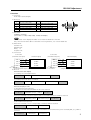
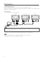
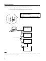
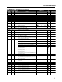
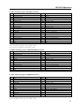
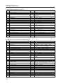
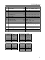
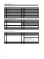
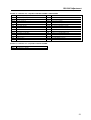
PDP-427CMX INDUSTRIAL PLASMA DISPLAY PANEL
SERIAL COMMAND REFERENCE MANUAL (version 1.0)
This manual provides information for controlling the PDP-427CMX industrial plasma display panel
with an external communication device by using serial commands.
Released: January 23, 2007
TABLE OF CONTENTS
1
About the RS-232C Adjustment ............................................................................ 2
2
Interface .................................................................................................................. 3
3
Combination Connection ...................................................................................... 4
4
ID Assignment ........................................................................................................ 5
5
List of Commands.................................................................................................. 7
6
QUEST Commands ................................................................................................ 15
RS-232C Adjustment
RS-232C Adjustment
This display has an RS-232C terminal. It is possible to use a PC to make various adjustments and settings.
1 About the RS-232C Adjustment
Adjustments using the RS-232C:
• The adjustments are written to the same memory area as for the integrator mode (refer to section 5.4.4, “PICTURE,
White Balance and SCREEN Position Adjustment Values Memory Area Tables” (pg. 257 to 261)).
Note
(1) Assign an ID before using the RS-232C adjustment. Include the panel ID in the RS-232C command.
For details, refer to section 5.5.2, “Interface” (pg. 263).
(2) Of the adjustment values and setting items set by RS-232C commands, there are some items that are
stored in memory and some that are not. For details, refer to section 5.5.5, “List of RS-232C Commands”
(pg. 267). Also, when storing values in “last” memory, the conditions described in section 5.1.5, “Last
Memory” (pg. 170), must be satisfied.
(3) <OSDS00>/<OSDS01> (OSD display disable/enable setting)
Regardless of the setting, the following items can be displayed.
• Menu display (menu mode, integrator mode)
• Warnings before Auto Power OFF or Power Management operation
• Warning of high temperature inside the panel
• Display announcing that the FUNCTIONAL LOCK is set and the FUNCTIONAL LOCK setting display
• Display call (including holding a button down)
(4) When using RS-232C commands, control the input signal as well as the power. If the power is ON when
there is no signal, the display continues to have a weak discharge. This activity can affect the life of the
display.
2
RS-232C Adjustment
2 Interface
1) Connector
D-sub 9 pins (male/straight)
2) Pin layout
Pin No.
1
2
3
4
5
Signal
NC (not connected)
TxD (Transmit Data)
RxD (Receive Data)
NC (not connected)
GND
Pin No.
6
7
8
9
1
Signal
NC (not connected)
NC (not connected)
RTS (Request To Send)
NC (not connected)
5
6
9
3) Baud Rate
9 600 bps (standard)
(switch-able to 1 200, 2 400, 4 800, 19 200, 38 400 bps)
Note
The baud rate of this display should be set to match the baud rate of the PC.
Also, when the RS-232C cable is extended over a long distance, use a slower baud rate.
4) Data format
Start bit: 1 bit
Data bit: 8 bit
Parity: no
Stop bit: 1 bit
5) Connection
Control PC
(with D25 serial port )
RXD 3
TXD 2
CTS 5
GND 7
Control PC
(with D9 serial port)
Plasma Display
2
3
2
2 TXD
3 RXD
8 RTS
5 GND
RXD 2
TXD 3
CTS 8
GND 5
* D-sub 9-pin/D-sub 25-pin conversion tables are now available on the market.
Plasma Display
2
3
2
2 TXD
3 RXD
8 RTS
5 GND
Straight Cable
6) Protocol
From the PC to the display
(1) Sending one command at a time:
STX (02 hex)
ID (2 Byte)
COMMAND (3 Byte or 6 Byte)
ETX (03 hex)
(2) Sending numerical direct commands:
STX (02 hex)
ID (2 Byte)
COMMAND (3 Byte)
ARGUMENT (3 Byte)
ETX (03 hex)
ID, COMMAND, ARGUMENT are transmitted as ASCII characters.
From the display to a PC
(1) Echo back (Normal response)
Command received and returned but the ID is not returned.
STX (02 hex)
COMMAND (3 Byte or 6 Byte)
ETX (03 hex)
Received command is a numerical direct effect command and numerical data is returned:
STX (02 hex)
COMMAND (3 Byte)
ARGUMENT (3 Byte)
ETX (03 hex)
(2) Error (Abnormal response)
Received command is a non-corresponding command, ‘ERR’ is returned:
STX (02 hex)
ERR (3 Byte)
ETX (03 hex)
Received command cannot be processed (when PON is received when the power is already ON, etc.), ‘XXX’ is
returned:
STX (02 hex)
XXX (3 Byte)
ETX (03 hex)
3
RS-232C Adjustment
3 Combination Connection
When controlling/adjusting panels, it is convenient to connect several displays to one PC.
By performing a combination connection and assigning IDs to the panels, it is possible to control and adjust several
displays at the same time or separately.
Connection method:
Connect the panels as shown in the figure below.
First Panel
IN
PC
OUT
COMBINATION
OUT
Second Panel
IN
RS-232C
OUT
IN
RS-232C
COMBINATION
IN
Third Panel
OUT
COMBINATION
RS-232C
IN
OUT
Combination cable
Combination cable
Note
Only the combination IN terminal or the RS-232C terminal can be used at the same time. Connecting them at the
same time could cause errors. Also, do not pair combination IN terminals or combination OUT terminals. Doing so
could cause communication to fail.
It is possible to use a general-purpose mini DIN 6-pin (straight) cable for the combination cable.
Note
To output RS-232C signals from the combination OUT terminal, an ID must be assigned.
For details, refer to section, 5.5.4, “ID Assignment” (pg. 265).
4
RS-232C Adjustment
4 ID Assignment
The ID is assigned from the PC.
Commands: <IDC> (ID CLEAR) ........ Clears the assigned ID
<IDS> (ID SET) ............. Assigns an ID
IDS is only effective when an ID is not assigned.
IDs are assigned starting from the panel closest to the PC.
Example: Case of 4 displays (assigning IDs with the PC for the first time)
First, connect an RS-232C and combination cables. (Refer to section 5.5.3, “Combination Connection” (pg.
264).)
PC
Set #1
±
ID = 01 OUT
Set #2
IN
ID = 02 OUT
Set #3
IN
ID = 03 OUT
Set #4
IN
ID = 04
RS-232C connection
Sent commands:
1 <01 IDS>
‘
2 <02 IDS>
‘
3 <03 IDS>
‘
4 <04 IDS>
By sending RS-232C commands in this order, it is possible to assign an ID for each panel.
When a panel has a PC-assigned ID, it can only receive commands containing the ID. Assign an ID before sending a
command.
Characters that can be used for an ID include, 0 - 9 and A - F (there is not distinction between upper case and lower case
letters).
An ∗ (asterisk) can be used as follows:
<∗∗IDC>: Clear the IDs assigned for all panels
<2∗IN1>: The input for which the first digit is 2 is set to INPUT1
Precautions when assigning IDs
Panels connected after a display’s ID has been cleared cannot be operated with RS-232C commands.
When the <∗∗IDC> command is sent, the IDs for all the sets from Set #1 to Set #4 are cleared. Only the first panel,
which is directly connected to the PC, can be controlled.
Send the command <01 IDS> to control the next panel. Continue setting IDs in this way for the remaining panels to
once again control the displays.
Note
When the IDs are set, when one or both of the IDs before a command is sent from the PC is an ∗, there is no echo.
When sending more commands, wait six seconds before sending the next command.
Example) When ∗∗OOO and ∗1OOO or 1∗OOO (OOO is the command) are sent from the PC, operation is performed
but there is no echo.
5
RS-232C Adjustment
Under the connection conditions shown below, use a combination cable for up to 16 panels.
Conditions: 1 Length of RS-232C cable connecting PC to Plasma Display: 5 m
2 Combination cable length: 5 m each
3 Wire specifications for linking cable: Mini Din 6-pin straight (7 strand cable)
For one strand, suitable for AWG28:
Cross-section area = 0.08 mm2
≠
7 strands × π r2 = 7 × 3.14 × 0.062 = 0.079 mm2 ≠ 0.08 mm2
PC
Plasma Display
1
RS-232C
5m
OUT
IN
2
OUT
Combination cable 5m
IN
3
OUT
IN
#
Note
For details on the number of displays that can be connected in series using the video OUT terminal (INPUT1, 4), refer to
section 2.3, “Controls and Connectors” (pg. 12).
6
RS-232C Adjustment
5 List of RS-232C Commands (Command 434CMX = Command 43MXE1 / Command 505CMX =
Command 50MXE10 , 50MXE11 , 50MXE1 , 50MXE1-S / Command 425CMX = Command 42MXE10)
7 Normal Operation Related Commands
Command
Command
Command
434CMX
427CMX
Function
425CMX
505CMX
507CMX
POWER
+
+
POF
Turns the power OFF.
+
+
PON
Turns the power ON.
INPUT SELECT
+
+
Displays the present input.
INP
+
+
Switches the main screen to INPUT1.
INPS01
+
+
Switches the main screen to INPUT2.
INPS02
+
+
Switches the main screen to INPUT3.
INPS03
+
+
Switches the main screen to INPUT4.
INPS04
+
+
Switches the main screen to INPUT5.
INPS05
+
+
Switches the main screen to INPUT1.
IN1
+
+
Switches the main screen to INPUT2.
IN2
+
+
Switches the main screen to INPUT3.
IN3
+
+
Switches the main screen to INPUT4.
IN4
+
+
Switches the main screen to INPUT5.
IN5
+
+
Switches the sub screen to INPUT1.
SSIS01
+
+
Switches the sub screen to INPUT2.
SSIS02
+
+
Switches the sub screen to INPUT3.
SSIS03
+
+
Switches the sub screen to INPUT4.
SSIS04
+
+
Switches the sub screen to INPUT5.
SSIS05
+
Outputs main input to the full screen.
–
SWM
+
Outputs sub input to the full screen.
–
SWS
SCREEN SIZE
+
+
Executes auto-setup.
AST
+
+
Displays the present screen size.
SZM
+
+
Sets SCREEN SIZE to DOT BY DOT.
SZMS00
+
+
Sets SCREEN SIZE to 4 :3.
SZMS01
+
+
Sets SCREEN SIZE to FULL.
SZMS02
+
+
Sets SCREEN SIZE to ZOOM.
SZMS03
+
+
Sets SCREEN SIZE to WIDE.
SZMS05
+
Sets SCREEN SIZE to 14:9.
–
SZMS06
+
+
Sets SCREEN SIZE to UNDERSCAN.
SZMS09
+
Sets SCREEN SIZE to 2.35:1.
–
SZMS10
VIDEO
+
Turns video mute to OFF.
MTN
PMTS00
+
Turns video mute to ON.
MTY
PMTS01
+
Cancels FREEZE.
SLN
STLS00
+
Sets FREEZE.
SLY
STLS01
AUDIO
+
+
Adjusts audio volume.
VOL
+
Turns audio mute to OFF.
AMN
AMTS00
+
Turns audio mute to ON.
AMY
AMTS01
+
Sets the audio source to main.
–
AUSS01
+
Sets the audio source to sub.
–
AUSS02
MULTI SCREEN
+
+
Displays the present multi-screen.
MSC
+
Turns MULTI SCREEN to OFF.
–
MSCS00
+
Sets the PinP subscreen size to 1.
–
MSSS01
+
Sets the PinP subscreen size to 2.
–
MSSS02
+
Sets the PinP subscreen size to 3.
–
MSSS03
+
Sets the PinP subscreen size to 4.
–
MSSS04
+
+
Displays the present multi-screen type.
MST
+
+
Sets the MULTI SCREEN to 2 SCREEN (side by side 1)
MSTS01
+
+
Sets the MULTI SCREEN to PinP (lower right).
MSTS02
+
+
Sets the MULTI SCREEN to PinP (upper right).
MSTS03
+
+
Sets the MULTI SCREEN to PinP (upper left).
MSTS04
+
+
Sets the MULTI SCREEN to PinP (lower left).
MSTS05
Number direct
Last
Effective Minimum Maximum memory
Comment
000
042
7
RS-232C Adjustment
Command
Command
Command
434CMX
427CMX
Function
425CMX
505CMX
507CMX
+
+
Sets the MULTI SCREEN to PoutP (side by side, 2-L).
MSTS06
+
–
MSTS09
MSTS10
–
MSTS11
–
–
MSTS12
+
SSI
FUNCTIONAL LOCK
+
FCL
+
FCLS00
+
FCLS01
+
FCLS02
+
FCLS03
+
FCLS04
+
+
+
+
+
Displays the present input to the SUB Screen.
+
+
+
+
+
+
Displays the present set value of the FUNCTIONAL LOCK.
Cancels FUNCTIONAL LOCK.
Prohibits operation of buttons on the display.
Prohibits operation of buttons on the remote control.
Prohibits operation of buttons on the display/remote control.
Sets the memory lock
+
Turns off the OSD display that is now displayed.
OSD
DOF
+
Comment
Sets MULTI SCREEN to SWAP (switches between main
and sub screens).
Sets MULTI SCREEN to PoutP (side by side 2-R).
Sets MULTI SCREEN to 2-SCREEN (side by side 3).
Sets MULTI SCREEN to PoutP (side by side 4-L).
Sets MULTI SCREEN to PoutP (side by side 4-R).
MSTS08
–
Number direct
Last
Effective Minimum Maximum memory
7 “MENU”–“SETUP” related commands
Command
Command
Command
434CMX
427CMX
Function
425CMX
505CMX
507CMX
COLOR TEMP.
+
+
Displays the present set value of the color temperature.
CTP
+
+
Sets the color temperature to LOW.
CTPS01
+
+
Sets the color temperature to MID LOW.
CTPS02
+
+
Sets the color temperature to MIDDLE.
CTPS03
+
+
Sets the color temperature to MID HIGH.
CTPS04
+
+
Sets the color temperature to HIGH.
CTPS05
DNR
+
+
Displays the present set value of the DNR.
DNR
+
+
Sets digital NR to OFF.
DNRS00
+
+
Sets digital NR to LOW.
DNRS01
+
+
Sets digital NR to MIDDLE.
DNRS02
+
+
Sets digital NR to HIGH.
DNRS03
MPEG NR
+
+
Displays the present set value of the MPEG NR.
MNR
+
+
Sets MPEG NR to OFF.
MNRS00
+
+
Sets MPEG NR to LOW.
MNRS01
+
+
Sets MPEG NR to MIDDLE.
MNRS02
+
+
Sets MPEG NR to HIGH.
MNRS03
CTI
+
+
Displays the present set value of CTI.
CTR
+
+
Sets CTI to OFF.
CTRS00
+
+
Sets CTI to ON.
CTRS01
PURE CINEMA
+
+
Displays the present set value of PURE CINEMA.
PUC
+
+
Sets PURE CINEMA to OFF.
PUCS00
+
+
Sets PURE CINEMA to STANDARD.
PUCS01
COLOR DECORDING
+
+
Displays the present color decoding.
MCD
+
+
Sets COLOR DECORDING to RGB (VIDEO).
MCDS01
+
+
Sets COLOR DECORDING to COMPONENT1 (YCbCr).
MCDS02
+
+
Sets COLOR DECORDING to COMPONENT2 (YPbPr).
MCDS03
COLOR SYSTEM
+
+
Displays the present set value of the color system.
CLS
+
+
Sets color system to AUTO.
CLSS01
+
+
Sets color system to NTSC.
CLSS02
+
+
Sets color system to PAL.
CLSS03
+
+
Sets color system to SECAM.
CLSS04
8
Number direct
Last
Effective Minimum Maximum memory
Comment
RS-232C Adjustment
Command
Command
Command
434CMX
427CMX
Function
425CMX
505CMX
507CMX
+
+
CLSS05
Sets color system to 4.43NTSC.
+
+
CLSS06
Sets color system to PAL M.
+
+
CLSS07
Sets color system to PAL N.
SIGNAL FORMAT
+
+
SFT
Displays the present set value of the SIGNAL FORMAT.
+
+
SFTS01
Sets SIGNAL FORMAT to Type1.
+
+
SFTS02
Sets SIGNAL FORMAT to Type2.
+
+
SFTS03
Sets SIGNAL FORMAT to Type3.
+
+
SFTS04
Sets SIGNAL FORMAT to Type4.
+
–
SFTS05
Sets SIGNAL FORMAT to Type5.
+
–
SFTS06
Sets SIGNAL FORMAT to Type6.
+
–
SFTS07
Sets SIGNAL FORMAT to Type7.
+
–
SFTS08
Sets SIGNAL FORMAT to Type8.
+
–
SFTS09 Sets SIGNAL FORMAT to Type9.
+
–
SFTS20 Sets SIGNAL FORMAT to Type10.
+
–
SFTS10
Sets SIGNAL FORMAT to AUTO.
DVI
+
EDIS01
DSGS01
Sets the DVI connection signal to PC.
+
EDIS02
DSGS02
Sets the DVI connection signal to STB/DVD.
+
–
DBLS01
Sets the DVI BLACK LEVEL to LOW.
+
–
DBLS02
Sets the DVI BLACK LEVEL to HIGH.
Number direct
Last
Effective Minimum Maximum memory
Comment
Note 1
Note 1
Note 1
Note 1
Note 2
Note 2
New
New
Note 1: The operation differs between the PDP-434CMX/PDP-505CMX and PDP-425CMX/PDP-507CMX/PDP-427CMX
Note 2: EDIS01/02 only operates on the PDP-505CMX
7 “MENU”–“OPTION” related commands
Command
Command
Command
434CMX
427CMX
Function
425CMX
505CMX
507CMX
ENERGY SAVE
+
+
ESV
Displays the present set value of ENERGY SAVE.
Sets ENERGY SAVE to STANDARD (STANDARD1).
+
+
ESVS00
Number direct
Last
Effective Minimum Maximum memory
Comment
Sets STANDARD1
only on the 507CMX
ESVS01
ESVS02
ESVS03
ESVS04
–
+
+
+
+
+
+
+
+
+
ESVS05
Sets ENERGY SAVE to save energy.
Sets ENERGY SAVE to fixed brightness.
Sets ENERGY SAVE to mode 3 (long service life).
Sets ENERGY SAVE to AUTO.
Sets ENERGY SAVE to MUTE.
–
+
ESVS06
Sets ENERGY SAVE to standard 2.
TIMER
–
–
TSMS00
TSMS01
+
+
Turns summer time to OFF.
Turns summer time to ON.
–
TPH
+
Sets the hour of the present time.
000
023
–
TPM
+
Sets the minute of the present time.
000
059
–
TPW
+
Sets the day of week of the present time.
001
007
000 – 023: Set by
24-hour clock time
000 – 059: Set
for 60 minutes
001: Monday –
007; Saturday
Sets PROGRAM TIMER/REPEAT TIMER to OFF.
Sets PROGRAM TIMER to ON.
Sets REPEAT TIMER to ON.
New
Sets the ORBITER to OFF.
Sets the ORBITER to ON (AUTO1).
Sets the ORBITER to ON (AUTO2).
Sets the ORBITER to ON (AUTO3).
Sets SOFT FOCUS to OFF.
Sets SOFT FOCUS to 1.
Sets SOFT FOCUS to 2.
Sets SOFT FOCUS to 3.
Sets SOFT FOCUS to 4.
Sets SUB SCREEN FREEZE to OFF.
Sets SUB SCREEN FREEZE to SIDE BY SIDE.
Sets SUB SCREEN FREEZE to PinP.
+
–
TPTS00
+
–
TPTS01
+
–
TPTS02
ORBITER
+
OMN
ORBS00
+
OMY
ORBS01
+
–
ORBS02
+
–
ORBS03
SOFT FOCUS
+
–
SOFS00
+
–
SOFS01
+
–
SOFS02
+
–
SOFS03
+
–
SOFS04
SUB SCREEN FREEZE
+
–
SSTS00
+
–
SSTS01
+
–
SSTS02
New
New, and effective
only on the 507CMX
9
RS-232C Adjustment
7 “INTEGRATOR”–“PICTURE” related commands
Command
Command
Command
434CMX
427CMX
Function
425CMX
505CMX
507CMX
VIDEO QUALITY
+
+
Adjusts the contrast.
CNT
+
+
Adjusts the brightness.
BRT
+
+
Adjusts the horizontal enhance.
ENH
+
+
Adjusts the vertical enhance.
ENV
+
+
Adjusts the color.
COL
+
+
Adjusts the tint.
TNT
+
+
Adjusts the sharpness.
SHP
WHITE BALANCE
+
+
Adjusts R.HIGH of the white balance.
RHI
+
+
Adjusts G.HIGH of the white balance.
GHI
+
+
Adjusts B.HIGH of the white balance.
BHI
+
+
Adjusts G.LOW of the white balance.
GLW
+
+
Adjusts R.LOW of the white balance.
RLW
+
+
Adjusts B.LOW of the white balance.
BLW
COLOR DETAIL
+
+
Adjusts color detail red.
CGR
+
+
Adjusts color detail yellow.
CGY
+
+
Adjusts color detail green.
CGG
+
+
Adjusts color detail cyan.
CGC
+
+
Adjusts color detail blue.
CGB
+
+
Adjusts color detail magenta.
CGM
GAMMA
+
+
Displays the present set value of gradation.
GRA
+
Sets gradation GAMMA 1.8.
–
GRAS18
+
Sets gradation GAMMA 1.9.
–
GRAS19
+
Sets gradation GAMMA 2.0.
–
GRAS20
+
Sets gradation GAMMA 2.1.
–
GRAS21
+
Sets gradation GAMMA 2.2.
–
GRAS22
+
Sets gradation GAMMA 2.3.
–
GRAS23
+
Sets gradation GAMMA 2.4.
–
GRAS24
PRESET
Restores the PICTURE, W/B adjustment value of the integrator
+
+
STD
to the initial values.
Number direct
Last
Effective Minimum Maximum memory
000
000
000
000
000
000
000
255
255
015
015
127
060
015
000
000
000
000
000
000
255
255
255
255
255
255
000
000
000
000
000
000
060
060
060
060
060
060
Comment
7 “INTEGRATOR”–“SCREEN” related commands
Command
Command
Command
434CMX
427CMX
Function
425CMX
505CMX
507CMX
POSITION
+
+
Adjusts the horizontal position.
HPS
+
+
Adjusts the vertical position.
VPS
CLOCK/PHASE
+
+
Adjusts the CLOCK (PLL frequency).
CFR
+
+
Adjusts the PHASE (PLL phase).
CPH
SIZE
+
+
Adjusts the horizontal size.
HSI
+
+
Adjusts the vertical size.
VSI
PRESET
Restores the SCREEN adjustment value of the integrator to the
+
+
FRP
initial values.
Number direct
Last
Effective Minimum Maximum memory
000
000
255
255
000
000
255
031
000
000
064
064
Comment
7 “INTEGRATOR”–“SETUP” related commands
Command
Command
Command
434CMX
427CMX
Function
425CMX
505CMX
507CMX
SUB VOLUME
+
+
SVL
Adjusts the SUB VOLUME.
10
Number direct
Last
Effective Minimum Maximum memory
000
020
Comment
RS-232C Adjustment
7 “INTEGRATOR”–“OPTION” related commands
Command
Command
Command
434CMX
427CMX
Function
425CMX
505CMX
507CMX
SCREEN MASK
+
+
Displays the present set value of SCREEN MASK.
FMK
+
+
Sets SCREEN MASK to OFF.
FMKS00
+
+
Sets SCREEN MASK to inverse (negative – positive reversed).
FMKS02
+
+
Sets SCREEN MASK to white mask.
FMKS03
+
+
Sets SCREEN MASK to red mask.
FMKS04
+
+
Sets SCREEN MASK to green mask.
FMKS05
+
+
Sets SCREEN MASK to blue mask.
FMKS06
+
+
Sets SCREEN MASK to yellow mask.
FMKS07
SIDE MASK
+
+
Adjusts side mask RED.
RSL
+
+
Adjusts side mask GREEN.
GSL
+
+
Adjusts side mask BLUE.
BSL
+
–
SMAS00 Sets AUTO SIDE MASK to OFF.
+
–
SMAS01 Sets AUTO SIDE MASK to ON.
VIDEO WALL
+
+
Displays the set value of VIDEO WALL.
MGF
+
+
Sets VIDEO WALL to OFF.
MGFS00
+
–
Sets VIDEO WALL to DIVIDER:1.
MGFS11
+
–
Sets VIDEO WALL to DIVIDER:4.
MGFS12
+
–
Sets VIDEO WALL to DIVIDER:9.
MGFS13
+
–
Sets VIDEO WALL to DIVIDER:16.
MGFS14
+
–
Sets VIDEO WALL to DIVIDER:25.
MGFS15
Displays the present VIDEO WALL (accounting/not accounting
+
+
MGP
for expanded position/joints) setting.
+
+
nn=01 to 04: Sets display position during DIVIDER=2 x 2 (not
MGPSnn
accounting for joints).
nn=05 to 08: Sets display position during DIVIDER=2 x 2
(accounting for joints).
nn=10 to 18: Sets display position during DIVIDER=3 x 3 (not
accounting for joints).
nn=20 to 28: Sets display position during DIVIDER=3 x 3
(accounting for joints).
nn=30 to 3F: Sets display position during DIVIDER=4 x 4 (not
accounting for joints).
nn=40 to 4F: Sets display position during DIVIDER=4 x 4
(accounting for joints).
nn=50 to 68: Sets display position during DIVIDER=5 x 5 (not
accounting for joints).
nn=70 to 88: Sets display position during DIVIDER=5 x 5
(accounting for joints).
+
–
Executes AUTO ID setting.
IDA
+
–
Sets POWER ON DELAY mode to OFF.
PDES00
Sets POWER ON DELAY mode to ON (other than cases used for
+
–
PDES01
a higher than 16 screen system) or mode 1 (used for a higher
than 16 screen system).
+
Sets POWER ON DELAY mode 2 (used for a higher than 16
–
PDES02
screen system).
+
Sets ABL link to OFF.
–
LNKS00
+
Sets ABL link to ON.
–
LNKS01
RS-232C
+
+
Displays the present set value of baud rate.
BRA
+
+
Sets the RS-232C baud rate to 1200 bps.
BRAS01
+
+
Sets the RS-232C baud rate to 2400 bps.
BRAS02
+
+
Sets the RS-232C baud rate to 4800 bps.
BRAS03
+
+
Sets the RS-232C baud rate to 9600 bps.
BRAS04
+
+
Sets the RS-232C baud rate to 19200 bps.
BRAS05
+
+
Sets the RS-232C baud rate to 38400 bps.
BRAS06
ID NUMBER
+
+
Clears the ID number.
IDC
+
+
Sets the ID number.
IDS
Number direct
Last
Effective Minimum Maximum memory
Comment
000
000
000
255
255
255
New
New
11
RS-232C Adjustment
Command
Command
Command
434CMX
427CMX
Function
425CMX
505CMX
507CMX
FAN
+
+
Maximizes fan rotation control.
FCM
+
+
Automates fan rotation control.
FCA
Sets integrator’s fan rotation control maximum to apply a
–
–
FCU
brightness
OSD
+
Sets OSD display to OFF.
DIN
OSDS00
+
Sets OSD display to ON.
DIY
OSDS01
+
Displays expanded OSD.
–
OSSS01
+
Displays contracted OSD.
–
OSSS02
+
Sets the OSD display angle to horizontal.
–
OSAS01
+
Sets the OSD display angle to vertical.
–
OSAS02
FRONT INDICATOR
+
Sets the FRONT INDICATOR to OFF.
LEN
LESS00
+
Sets the FRONT INDICATOR to ON.
LEY
LESS01
COLOR MODE
+
Sets the COLOR MODE to NORMAL.
CM1
CLMS00
+
Sets the COLOR MODE to STUDIO.
CM2
CLMS01
UNDER SCAN
+
+
Sets the UNDERSCAN setting to OFF.
USCS00
+
+
Sets the UNDERSCAN setting to ON.
USCS01
+
+
Displays the present set value of UNDERSCAN.
USC
IMAGE PROCESS
+
–
Obtains the present IMAGE PROCESS setting.
IPR
+
–
Sets the IMAGE PROCESS to NORMAL.
IPRS01
+
–
Sets the IMAGE PROCESS to PURE.
IPRS02
+
–
Sets the IMAGE PROCESS to MONOTONE.
IPRS03
+
–
Sets the IMAGE PROCESS to HIGH CONTRAST.
IPRS04
–
–
IPRS05
Sets the IMAGE PROCESS to BLUE ONLY.
FRC
+
+
Displays the present set value of FRC.
FRC
+
Sets the FRC to OFF.
–
FRCS00
+
+
Sets the FRC to ON.
FRCS01
SEAMLESS INPUT SWITCH
+
–
Sets the SEAMLESS INPUT SWITCH mode to OFF.
SLSS00
+
–
Sets the SEAMLESS INPUT SWITCH mode to ON.
SLSS01
+
–
Sets the SEAMLESS SW SELECT 1 to INPUT1.
SL1S01
+
–
Sets the SEAMLESS SW SELECT 1 to INPUT2.
SL1S02
+
–
Sets the SEAMLESS SW SELECT 1 to INPUT3.
SL1S03
+
–
Sets the SEAMLESS SW SELECT 1 to INPUT4.
SL1S04
+
–
Sets the SEAMLESS SW SELECT 1 to INPUT5.
SL1S05
+
–
Sets the SEAMLESS SW SELECT 2 to INPUT1.
SL2S01
+
–
Sets the SEAMLESS SW SELECT 2 to INPUT2.
SL2S02
+
–
Sets the SEAMLESS SW SELECT 2 to INPUT3.
SL2S03
+
–
Sets the SEAMLESS SW SELECT 2 to INPUT4.
SL2S04
+
–
Sets the SEAMLESS SW SELECT 2 to INPUT5.
SL2S05
MIRROR
+
+
MIRS00
Sets mirror mode to OFF (normal display).
+
+
MIRS01
Performs left-right reversal with MIRROR MODE.
+
+
MIRS02
Performs up-down reversal with MIRROR MODE.
+
+
MIRS03
Performs up-down left-right reversal with MIRROR MODE.
MULTI SCREEN
+
Sets sub screen translucence to OFF (0%).
–
PTRS00
+
Sets sub screen translucence to 10 %.
–
PTRS01
+
Sets sub screen translucence to 20 %.
–
PTRS02
+
Sets sub screen translucence to 30 %.
–
PTRS03
+
Sets sub screen translucence to 40 %.
–
PTRS04
+
Sets sub screen translucence to 50 %.
–
PTRS05
+
Sets sub screen translucence to 60 %.
–
PTRS06
+
Sets sub screen translucence to 70 %.
–
PTRS07
+
–
Sets sub screen translucence to 80 %.
PTRS08
Number direct
Last
Effective Minimum Maximum memory
Note 1: The operation differs between the PDP-434CMX/PDP-505CMX and PDP-425CMX/PDP-507CMX/PDP-427CMX
12
Comment
New, and effective
only on the 507CMX
New
Note 1
RS-232C Adjustment
Command
Command
Command
434CMX
427CMX
Function
425CMX
505CMX
507CMX
+
Sets the BANNER PinP input to INPUT1.
–
BPIS01
+
Sets the BANNER PinP input to INPUT2.
–
BPIS02
+
Sets the BANNER PinP setting to OFF.
–
BPPS00
+
Sets the BANNER PinP setting to TOP3.
–
BPPS01
+
Sets the BANNER PinP setting to MID-HIGH.
–
BPPS02
+
Sets the BANNER PinP setting to MID-LOW.
–
BPPS03
+
Sets the BANNER PinP setting to BOTTOM3.
–
BPPS04
+
–
BPPS05 Sets the BANNER PinP setting to TOP2.
+
–
BPPS06 Sets the BANNER PinP setting to BOTTOM2.
+
–
BPPS07 Sets the BANNER PinP setting to TOP1.
+
–
BPPS08 Sets the BANNER PinP setting to BOTTOM1.
+
–
BPPS09 Sets the BANNER PinP setting to LEFT.
+
–
BPPS10 Sets the BANNER PinP setting to RIGHT.
+
–
PFAS00 PIP fade in function ineffective.
+
–
PFAS01 PIP fade in function effective.
+
–
PFAS10 PIP fade in (only when PIP fade in function is effective).
+
–
PFAS11 PIP fade off (only when PIP fade in function is effective).
FUNCTION
+
+
Executes FUNCTION DEFAULT.
FDT
Number direct
Last
Effective Minimum Maximum memory
Comment
New
New
New
New
New
New
New
New
New
New
7 Other commands
Command
Command
Command
434CMX
427CMX
425CMX
505CMX
507CMX
DISPLAY CALL
+
–
DITS01
+
–
DITS02
+
–
IM0
+
–
IM1
+
–
IM2
+
–
IM3
+
–
IM4
+
–
IM5
+
–
IM6
+
–
IMD
AUXILIARY COMMAND
+
+
DW0
+
+
DWF
+
+
DWn
+
+
UP0
+
+
UPF
+
+
UPn
+
GST
QST
+
GPI
QPI
+
GWB
QWB
+
GPS
QPS
+
GSS
QSS
+
GSO
QSO
+
–
QAP
+
–
QCI
+
–
QSU
OTHER
–
–
MRKS00
–
–
MRKS01
–
–
RMCS10
–
–
RMCS11
–
–
RMCS12
–
–
RMCS13
–
–
RMCS14
–
–
RMCS25
Number direct
Function
Displays DISPLAY CALL 1.
Displays DISPLAY CALL 2.
INFORMATION write-in (1-3 characters).
INFORMATION write-in (4-6 characters).
INFORMATION write-in (7-9 characters).
INFORMATION write-in (10-12 characters).
INFORMATION write-in (13-15 characters).
INFORMATION write-in (16-18 characters).
INFORMATION write-in (19-21 characters).
Clears INFORMATION.
Last
Effective Minimum Maximum memory
Comment
Subtracts 10 from the adjustment value.
Minimizes the adjustment value.
Subtracts n from the adjustment value. (n=1~9)
Adds 10 to the adjustment value.
Maximizes the adjustment value.
Adds n to the adjustment value (n = 1 to 9).
Obtains status information.
Obtains integrator/PICTURE information.
Obtains integrator/WHITE BALANCE information.
Obtains integrator/SCREEN information.
Obtains SETUP information.
Obtains Menu Integrator/OPTION information.
Obtains various machine names.
Obtains time information.
Obtains audio status.
Sets mark display off.
Sets mark display on.
Remote control key: CURSOR RIGHT
Remote control key: CURSOR LEFT
Remote control key: CURSOR UP
Remote control key: CURSOR DOWN
Remote control key: SET
Remote control key: MENU
New
New
New
New
New
New
New
New
13
RS-232C Adjustment
Command
Command
Command
434CMX
427CMX
425CMX
505CMX
507CMX
–
–
RMCS26
–
–
RMCS27
–
–
RMCS28
–
–
RMCS29
–
–
RMCS30
–
–
RMCS31
–
–
RMCS32
–
–
RMCS33
–
–
RMCS34
–
–
RMCS35
–
–
RMCS36
–
–
RMCS37
14
Number direct
Function
Remote control key: POINT ZOOM
Remote control key: ID NO SET
Remote control key: CLEAR
Remote control key: FREEZE
Remote control key: STANDBY/ON
Remote control key: VOLUME UP
Remote control key: VOLUME DOWN
Remote control key: MUTING
Remote control key: SCREEN SIZE
Remote control key: SPLIT
Remote control key: SUB INPUT
Remote control key: PIP SHIFT
Last
Effective Minimum Maximum memory
Comment
New
New
New
New
New
New
New
New
New
New
New
New
RS-232C Adjustment
6 QUEST Commands
What are QUEST commands?
• Quest commands output TXD such as adjustment data from the panel’s microprocessor to a PC.
• Adjustment and other data is output in ASCII code.
Note Command names are given inside brackets < >.
• Data output format
STX (02hex)
Command
(3 Byte)
Data
····
Data
Checksum
(2 Byte)
ETX (03hex)
Note
• A QUEST command is invalid when no ID has not been assigned.
• A QUEST command is invalid when a wildcard (*) is used in the ID when sending the command.
7 Quest Command Table
Command
Command
Command
434CMX
427CMX
425CMX
505CMX
507CMX
+
GST
QST
+
GPI
QPI
+
GWB
QWB
+
GPS
QPS
+
GSS
QSS
+
GSO
QSO
+
–
QAP
+
–
QCI
+
–
QSU
Function
Number direct
Last
Effective Minimum Maximum memory
Comment
Obtains status information.
Obtains integrator/PICTURE information.
Obtains integrator/WHITE BALANCE information.
Obtains integrator/SCREEN information.
Obtains SETUP information.
Obtains Menu Integrator/OPTION information.
Obtains audio status.
Obtains time information.
Obtains various machine names.
15
RS-232C Adjustment
1) Obtaining QST Status Information
Sequence
1
2
3
4
5
6
7
Data Content
STX
Command echo-back
Generation information
Inch information
Forwarding
Power source state
During standby: Standby cause
Size
1 Byte
3 Byte
1 Byte
1 Byte
1 Byte
1 Byte
1 Byte
During power supply: main screen signal status
8
9
During standby or 1 screen display: dummy data
During 2-screen display: sub screen signal status
1 Byte
Main input function information
3 Byte
10
Sub input function information
3 Byte
11
Main screen size information
1 Byte
12
Two-screen display state
1 Byte
13
Functional lock information
1 Byte
14
15
16
17
18
19
20
21
22
Temperature information 1 (interior)
Temperature information 2 (outside air)
Temperature information 3 (SLOT)
Serial No.
Dummy data
Dummy data
HOUR METER
Check sum
ETX
3 Byte
3 Byte
3 Byte
15 Byte
3 Byte
2 Byte
5 Byte
2 Byte
1 Byte
Remarks
02hex
QST (fixed)
5 (fixed)
4: 42 inch 5: 50 inch
M (fixed)
S: Standby status P: Power supplied status
N: Normal standby time
W: Standby time based on POWER MANAGEMENT
S: Standby time based on SD or PD
N: normal signal input time
L: no signal input time
O: OUT OF RANGE signal input time
N: normal signal input time
L: no signal input time
O: OUT OF RANGE signal input time
IN1: INPUT1 IN2: INPUT2 IN3: INPUT3
5 digit number
03hex
Note 1) During standby and during a single screen display, the unit outputs the value that is in memory.
Note 2) During standby and immediately after POWER ON, the correct value is not output.
In this case, please obtain the information after waiting a short period of time after POWER ON.
These types of information are output as reference information (these are not guaranteed information).
Normally refer to temperature information 3.
16
IN4: INPUT4
IN5: INPUT5
IN1: INPUT1 IN2: INPUT2 IN3: INPUT3 IN4: INPUT4
IN5: INPUT5 Note1)
0: DOT BY DOT 1: 4:3 2: FULL 3: ZOOM 5: WIDE 6: 14:9
9: UNDERSCAN A: 2.35:1
0: OFF (1 screen)
1: SIDE BY SIDE 1
2: PinP (lower right) 3: PinP(upper right)
4: PinP (upper left)
5: PinP(lower left)
6: SIDE BY SIDE 2-L 9: SIDE BY SIDE 2-R
A: SIDE BY SIDE 3
B: SIDE BY SIDE 4-L
C:SIDE BY SIDE 4-R
0: LOCK OFF 1: BUTTONS LOCK 2: IR LOCK
2: IR LOCK
3: IR&BUTTONS LOCK
4: MEMORY LOCK
Temperature inside the set (Centigrade) Note 2)
Outside air temperature (Celsius) Note 2)
SLOT temperature (Celsius) Note 2)
15 digit character string
RS-232C Adjustment
2) <QPI> Obtaining Integrator/PICTURE information
Sequence
1
2
3
4
5
6
7
8
9
10
11
12
13
14
15
16
17
18
19
Data Content
STX
Command echo-back
CONTRAST
BRIGHTNESS
C,DETAIL R (RED)
C,DETAIL Y (YELLOW)
C,DETAIL G (GREEN)
C,DETAIL C (CYAN)
C,DETAIL B (BLUE)
C,DETAIL M (MAGENTA)
H.ENHANCE
V.ENHANCE
COLOR
TINT
SHARPNESS
Main input function
Main screen size information
Check sum
ETX
Size
1 Byte
3 Byte
3 Byte
3 Byte
3 Byte
3 Byte
3 Byte
3 Byte
3 Byte
3 Byte
3 Byte
3 Byte
3 Byte
3 Byte
3 Byte
3 Byte
1 Byte
2 Byte
1 Byte
Remarks
02hex
QPI (fixed)
000 to 255 Note 1)
000 to 255 Note 1)
000 to 060 Note 1)
000 to 060 Note 1)
000 to 060 Note 1)
000 to 060 Note 1)
000 to 060 Note 1)
000 to 060 Note 1)
000 to 015 Note 1), Note 2)
000 to 015 Note 1), Note 2)
000 to 127 Note 1), Note 3)
000 to 060 Note 1), Note 3)
000 to 015 Note 1), Note 3)
Same as item 9 of QST commands
Same as item 11 of QST commands
03hex
Note 1) If the signal type is not confirmed, dummy data is output.
Note 2) During video signal input, dummy data is output.
Note 3) During PC signal input, dummy data is output.
3) <QWB> Obtaining integrator/WHITE BALANCE information
Sequence
1
2
3
4
5
6
7
8
9
10
11
12
Data Content
STX
Command echo-back
R.HIGH
G.HIGH
B.HIGH
R.LOW
G.LOW
B.LOW
Main input function
Main screen size
Check sum
ETX
Size
1 Byte
3 Byte
3 Byte
3 Byte
3 Byte
3 Byte
3 Byte
3 Byte
3 Byte
1 Byte
2 Byte
1 Byte
Remarks
02hex
QWB (fixed)
000 to 255 Note 1)
000 to 255 Note 1)
000 to 255 Note 1)
000 to 255 Note 1)
000 to 255 Note 1)
000 to 255 Note 1)
Same as item 9 of QST commands
Same as item 11 of QST commands
Size
1 Byte
3 Byte
3 Byte
3 Byte
3 Byte
3 Byte
3 Byte
3 Byte
3 Byte
1 Byte
2 Byte
1 Byte
Remarks
02hex
QPS (fixed)
000 to 255 Note 1)
000 to 255 Note 1)
000 to 064 Note 1)
000 to 064 Note 1)
000 to 255 Note 1), Note 2)
000 to 031 Note 1), Note 2)
Same as item 9 of QST commands
Same as item 11 of QST commands
03hex
Note 1) If the signal type is not confirmed, dummy data is output.
4) <QPS> Obtaining integrator/SCREEN information
Sequence
1
2
3
4
5
6
7
8
9
10
18
19
Data Content
STX
Command echo-back
H.POSITION
V.POSITION
H.SIZE
V.SIZE
CLOCK
PHASE
Main input function
Main screen size information
Check sum
ETX
03hex
Note 1) If the signal type is not confirmed, dummy data is output.
Note 2) During DVI or video input, dummy data is output.
17
RS-232C Adjustment
5) <QSS> Obtaining SETUP information
Sequence
Data Content
1
STX
2
Command echo-back
3
COLOR TEMP.
Size
1 Byte
3 Byte
1 Byte
4
5
6
7
8
9
10
11
POWER MGT.
AUTO POWER OFF
DNR
MPEG NR
CTI
PURECINEMA
COLOR DECODING
COLOR SYSTEM
1 Byte
1 Byte
1 Byte
1 Byte
1 Byte
1 Byte
1 Byte
1 Byte
12
13
14
15
DVI SET UP (PLUG/PLAY)
DVI SET UP (BLACK LEVEL)
BRT.ENHANCE
SUB VOLUME
1 Byte
1 Byte
1 Byte
2 Byte
16
17
18
19
Main input function
Main screen size information
Check sum
ETX
3 Byte
1 Byte
2 Byte
1 Byte
Remarks
02hex
QSS (fixed)
1: LOW 2: MID LOW 3: MIDDLE 4: MID HIGH
5: HIGH Note 1)
0: OFF 1: ON
0: DISABLE 1: ENABLE
0: OFF 1: LOW 2: MIDDLE 3: HIGH Note 1)
0: OFF 1: LOW 2: MIDDLE 3: HIGH Note 1)
0: OFF 1: ON Note 1)
0: OFF 1: ON Note 1)
1: RGB 2: COMP1 3: COMP2 Note 1)
1: AUTO 2: NTSC 3: PAL 4: SECAM 5: 4.43NTSC
6: PAL M 7: PAL N Note 1)
1: PC
2: VIDEO Note 1)
1: LOW 2: HIGH Note 1)
0: OFF 1: ON Note 1)
00 to 20
Same as item 9 of QST commands
Same as item 11 of QST commands
03hex
Note 1) In the case of set data that cannot be output because of the type of input signal, dummy data is output.
6) <QSO> Obtaining menu integrator/OPTION information
Sequence
Data Content
1
STX
2
Command echo-back
3
ENERGY SAVE
Size
1 Byte
3 Byte
1 Byte
4
5
6
7
8
9
10
11
PROGRAM/REPEAT timer
SCREEN MANAGEMENT (ORBITER)
SCREEN MANAGEMENT (SOFT FOCUS)
AUTO SETUP MODE
AUTO FUNCTION
PIP DETECT
SPLIT FREEZE
SCREEN MASK
1 Byte
1 Byte
1 Byte
1 Byte
1 Byte
1 Byte
1 Byte
1 Byte
12
13
14
15
SIDE MASK R-LEVEL
SIDE MASK G-LEVEL
SIDE MASK B-LEVEL
VIDEO WALL (MODE)
3 Byte
3 Byte
3 Byte
1 Byte
16
17
18
19
20
21
22
23
24
25
26
VIDEO WALL (POSITION)
VIDEO WALL (TYPE)
VIDEO WALL (POWER ON DELAY)
VIDEO WALL (ABL LINK)
Spare (dummy)
FAN CONTROL
OSD DISPLAY
OSD SIZE
OSD ANGLE
FRONT INDICATOR
COLOR MODE
2 Byte
1 Byte
1 Byte
1 Byte
1 Byte
1 Byte
1 Byte
1 Byte
1 Byte
1 Byte
1 Byte
18
Remarks
02hex
QSO (fixed)
0: STANDARD1 1: MODE1 2: MODE2 3: MODE3
4: AUTO
5: MUTE
6: STANDARD2
0: OFF 1: PROGRAM 2: REPEAT
0: OFF 1: MODE1 2: MODE2 3: MODE3
0: OFF 1: 1 2: 2 3: 3 4: 4
0: INACTIVE 1: ACTIVE
0: OFF 1: INPUT1 2: INPUT4
0: INACTIVE 1: ACTIVE
0: OFF 1: SIDE BY SIDE 2: PIP
0: OFF 2: INVERSE 3: WHITE 4: RED 5: GREEN 6: BLUE
7: YELLOW
000 to 255
000 to 255
000 to 255
0: OFF 1: 1 screen 2: 4 screens (2 x 2) 3: 9 screens (3 x 3)
4: 16 screens (4 x 4) 5: 25 screens (5 x 5)
01 to 56
0: NORMAL 1: ADJUSTED
0: OFF
1: ON 2: MODE1 3: MODE2
0: OFF
1: ON
* (FIX)
1: AUTO
2: MAX
0: OFF
1: ON
0: LARGE
1: SMALL
0: H
1: V
0: OFF
1: ON
1: NORMAL 2: STUDIO
RS-232C Adjustment
Sequence
Data Content
27
PRO USE UNDERSCAN
28
PRO USE IMAGE PROCESS
Size
1 Byte
1 Byte
29
30
31
32
33
34
35
36
37
38
39
40
41
42
43
PRO USE SYGNAL TYPE
FRC
POWER ON MODE INPUT
POWER ON MODE MULTI MODE
POWER ON MODE MULTI INPUT 1
POWER ON MODE MULTI INPUT 2
POWER ON MODE VOLUME
SEAMLESS SW
SEAMLESS SW SELECT1
SEAMLESS SW SELECT2
MIRROR MODE
MULTI SCREEN SET (S BY S SIZE)
MULTI SCREEN SET (S BY S LAYOUT)
MULTI SCREEN SET (PIP SIZE)
MULTI SCREEN SET (TRANSLUCENT)
1 Byte
1 Byte
1 Byte
1 Byte
1 Byte
1 Byte
44
MULTI SCREEN SET (BANNER PIP)
1 Byte
45
46
MULTI SCREEN SET (BANNER INPUT)
Main input function
1 Byte
3 Byte
47
48
49
Main screen size information
Check sum
ETX
1 Byte
2 Byte
1 Byte
7 POWER ON MODE INPUT
Input functions
(response)
0
1 Byte
1 Byte
1 Byte
1 Byte
1 Byte
1 Byte
2 Byte
1 Byte
Remarks
0: OFF
1: ON
1: NORMAL 2: PURE 3: MONOTONE 4: BLUE ONLY
5: HIGH CONTRAST
1: MOTION 2: STILL 3: NONE STD
0: OFF
1: ON
See the table below.
See the table below.
1: INPUT 2: INPUT2 3: INPUT3 4: INPUT4 5: INPUT5
1: INPUT 2: INPUT2 3: INPUT3 4: INPUT4 5: INPUT5
0 to 42: In the case of last memory, FF
0: OFF
1: ON
1: INPUT 2: INPUT2 3: INPUT3 4: INPUT4 5: INPUT5
1: INPUT 2: INPUT2 3: INPUT3 4: INPUT4 5: INPUT5
0: OFF 1: X 2: Y 3: XY
1: NORMAL 2: FULL
1: MODE1
2: MODE2 3: MODE3
1: 1 (SMALL) to 4: 4 (LARGE)
0: OFF 1: 10 % 2: 20 % 3: 30 % 4: 40 % 5: 50 %
6: 60 % 7: 70 % 8: 80 %
0: OFF 1: BOTTOM1 2: BOTTOM2 3: BOTTOM3
4: MID LOW 5: MID HIGH 6: TOP3 7: TOP2 8: TOP1
9: LEFT A: RIGHT
1: INPUT1 2: INPUT2
Input functions of the main screen (refer to the following table for
details)
Main screen size (refer to the following table for details)
03hex
7 POWER ON MODE MULTI MODE
LAST
Input functions
(response)
1
SIDE BY SIDE1
1
INPUT1
2
SIDE BY SIDE2
2
INPUT2
3
SIDE BY SIDE3
3
INPUT3
4
BOTTOM LEFT
4
INPUT4
5
BOTTOM RIGHT
5
INPUT5
6
TOP RIGHT
A
MULTI
7
TOP LEFT
INPUT
7 Main screen input function
INPUT
7 Main screen size
Input function
IN1
Input
INPUT1
Main screen size
0
Screen size
DOT BY DOT
IN2
INPUT2
1
4:3
IN3
INPUT3
2
FULL
IN4
INPUT4
3
ZOOM
IN5
INPUT5
5
WIDE
***
Unconfirmed (standby time)
6
14 : 9
9
UNDER SCAN
A
2.35 : 1
19
RS-232C Adjustment
7) <QSU> obtaining the audio status
Sequence
1
2
3
4
5
6
7
8
9
10
11
Data Content
STX
Command echo-back
Main volume
Audio mute status
INPUT1 sub volume
INPUT2 sub volume
INPUT3 sub volume
INPUT4 sub volume
INPUT5 sub volume
Check sum
ETX
Size
1 Byte
3 Byte
3 Byte
1 Byte
3 Byte
3 Byte
3 Byte
3 Byte
3 Byte
2 Byte
1 Byte
Remarks
02hex
QSU (fixed)
000 to 042
0: OFF 1: ON
000 to 020
000 to 020
000 to 020
000 to 020
000 to 020
03hex
8) <QCI> Obtaining time information
Sequence
Data Content
1
STX
2
Command echo-back
3
Time information
4
5
Dummy data
Day of week
Size
1 Byte
3 Byte
2 Byte
2 Byte
2 Byte
8 Byte
1 Byte
6
7
Check sum
ETX
2 Byte
1 Byte
Remarks
02hex
QCI (fixed)
Hour (24 hour system) 00 to 23 Note 1)
Minute 00 to 59 Note 1)
Second 00 to 59 Note 1)
1: Sunday 2: Monday
5: Thursday 6: Friday
3: Tuesday 4: Wednesday
7: Saturday Note 1)
03hex
Note 1) During standby and when this command was initially set, the value at the time that power was finally shut off is transmitted.
9) <QAP> Obtaining machine name
Sequence
Data Content
1
STX
2
Command echo-back
3
Machine name information
4
5
20
Check sum
ETX
Size
1 Byte
3 Byte
18 Byte
2 Byte
1 Byte
Remarks
02hex
QAP (fixed)
42 inch:
A (North America model): PDP-427CMX********
G (Europe-general model): PDP-42MXE20*******
50 inch:
J (Japan model): PDP-507CMX-JP*****
A (North America model): PDP-507CMX********
G (Europe-general/CKD model): PDP-50MXE20*******
GS (Europe-general/silver model): PDP-50MXE20*******
03hex
RS-232C Adjustment
7 Table of commands not compatible with PDP-434CMX to PDP-425CMX
AJN
AJY
COF
COFS00
COFS01
DPR
FXO
FRCS02
FRCS03
GRAS04
GRAS05
GRAS06
GRAS07
LNN
LNY
Ends 232C integrator adjustment mode.
Starts 232C integrator adjustment mode.
Displays present color off setting.
Does not set color off.
Sets color off.
Resets still picture movement function.
Selects audio output fix.
Sets FRC to MODE2.
Sets FRC to MODE3.
Sets gradation to “DRE MID”.
Sets gradation to “DRE HIGH”.
Sets gradation to “DRE LOW”.
Sets gradation to “HIGH CONTRAST”.
Prohibits loudness.
Permits loudness
MCN
MCY
MGFS01
MSCS01
SIM
SIMS01
SIMS02
SIMS03
SZMS04
SZMS08
MIR
PLN
PLY
PUCS02
VRO
Turns off MASK CONTROL.
Turns on MASK CONTROL.
Turns on VIDEO WALL.
Turns on MULTI SCREEN.
Displays present setting of SIDE MASK.
Sets setting of SIDE MASK to normal.
Sets setting of SIDE MASK to overlay 1.
Sets setting of SIDE MASK to overlay 2.
Sets screen size to CINEMA.
Sets screen size to FULL 1035i.
Displays present MIRROR MODE setting
Turns off center brightness correction.
Turns on center brightness correction.
Sets PURE CINEMA to advance.
Selects audio output variable.
7 Table of commands not compatible with PDP-505CMX
EDIS01
EDIS02
Sets DVI SELECT to PC.
Sets DVI SELECT to VIDEOS1.
21
RS-232C Adjustment
7 Check Sum
This is data to which 2-Byte ASCII code is added to a data group returned by a QUEST command.
PC side
STX
ID
QUEST command
ETX
02 (hex)
2 Byte
3 Byte
03 (hex)
Set side
STX
QUEST command
Data
Check sum
ETX
02 (hex)
3 Byte
*Byte
2 Byte
03 (hex)
A detailed example is given below.
Example) The check sum value that is added when the QUEST command “QAA” returned the following 6-Byte data string.
Data group (ASCII)
+ check sum
QUEST command
Data (6 Byte)
Check sum
QAA
100128
xx (before calculation)
≠
47
41
41
31 30 30 31 32 38
The data group is put into binary code one
character at a time then displayed (only the
last two digits are displayed).
When these values are added the result is 1F5 (hex).
≠
xx, where xx is 0B (hex), is added to 1F5 so the last two digits are 00 (in this case 200).
≠
As the data format, OB is converted to ASCII code and sent.
≠
The following data is output from the Plasma Display side.
STX
QUEST command
Data
Check sum
ETX
02 (hex)
QAA
100128
0B
03 (hex)
* The returned data group is in capital letters. Please keep this in mind when introducing it into the binary
display.
7 Examples of check sum applications
Example 1) When the data is missing 1 Byte
STX
QUEST command
Data
Check sum
ETX
02 (hex)
QAA
100 (missing data) 28
0B
03 (hex)
47
41
31 30 30 32 38
The data group is calculated according to rules by a PC application,
and when these values are added the result is 1C4 (hex).
≠
A value xx, where xx is 3C (hex), is added to 1C4 such that the last
two digits are 00 (in this case 200).
≠
Here, the check sum [OB (hex)] and the calculated [3C (hex)] do not match.
≠
Since they do not match, the PC application sends the QUEST command
again and gets the data again.
Example 2) When 1 Byte of data in the data is unreadable
STX
QUEST command
Data
Check sum
ETX
02 (hex)
QAA
100328
0B
03 (hex)
47
41
31 30 33 30 32 38
The data group is calculated according to rules by a PC application,
and when these values are added the result is 1F7 (hex).
≠
A value xx, where xx is 09 (hex), is added to 1F7 such that the last
two digits are 00 (in this case 200).
≠
Here, the check sum [OB (hex)] and the calculated [09 (hex)] do not match.
≠
22
Since they do not match, the PC application sends the QUEST command
again and gets the data again.