1
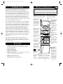
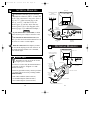
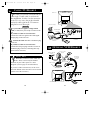
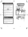
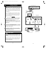
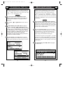
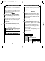
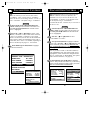
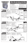
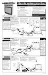
Net 1Card IB
2/15/00 12:17 PM
Page 1
Professional Color Television
NET1CARD
®
TELEVISION
OWNER’S
MANUAL
AND
SET-UP
GUIDE
IndustryStandards
™
Net 1Card IB
2/15/00 12:17 PM
Page 2
TABLE OF CONTENTS
KNOW THESE SAFETY SYMBOLS
t
CAUTION
RISK OF ELECTRIC SHOCK
DO NOT OPEN
s
Getting Started
Warning/Precautions . . . . . . . . . . . . . . . . . . .2
Introduction . . . . . . . . . . . . . . . . . . . . . . . . .4
Features . . . . . . . . . . . . . . . . . . . . . . . . . . . .4
Basic Remote Control Operations . . . . . . . . . . . . . . . .5
Unpacking and Installation . . . . . . . . . . . . . . . . . . .6-9
Input/Output Jacks . . . . . . . . . . . . . . . . . . . . . . . . . . .9
Hooking up the Net 1Card Television
Antenna TV Connections . . . . . . . . . . . .10-11
Cable TV Connections . . . . . . . . . . . . . .12-13
Audio/Video Input Connections . . . . . . . . . . . . . .14-15
S-Video Input Connections . . . . . . . . . . . . . . . . .16-17
On-Screen Menu Options
Commercial Settings . . . . . . . . . . . . . . . . . .18
• Commercial / Consumer Mode . . . . . . . .18
• Receiver / Transmitter / Factory . . . . . . . . . . . . .19
• Front Keypad / Cable / Exit . . . . . . . . . . . . . . . .20
Receiver Control . . . . . . . . . . . . . . . . . . . . . . . . . . .21
• Receiver Group IDs . . . . . . . . . . . . . . . . . . . . . .21
• Receiver Set IDs / Exit . . . . . . . . . . . . . . . . . . . .22
Transmitter Control . . . . . . . . . . . . . . . . . . . . . . . . .23
• Address Type / Group IDs . . . . . . . . . . . . . . . . . .23
• Receiver Power . . . . . . . . . . . . . . . . . . . . . . . . . .24
• Receiver Volume . . . . . . . . . . . . . . . . . . . . . . . . .25
• Receiver Channel . . . . . . . . . . . . . . . . . . . . . . . .26
• Receiver Lockout / Update Receiver TVs / Exit .27
• Receiver Reset . . . . . . . . . . . . . . . . . . . . . . . . . .29
Factory Test Menu . . . . . . . . . . . . . . . . . . . . . . . . . .30
Television Features . . . . . . . . . . . . . . . . . . . . . . . . . .31
Closed Captioning . . . . . . . . . . . . . . . . . . . . . . . . . .36
General Information
Index . . . . . . . . . . . . . . . . . . . . . . . . . . . . .37
Glossary . . . . . . . . . . . . . . . . . . . . . . . . . . .38
Troubleshooting . . . . . . . . . . . . . . . . . . . . .39
Warranty . . . . . . . . . . . . . . . . . . . . . . . . . . . . . . . . . .40
11
12
1
2
10
3
9
4
8
CAUTION: TO REDUCE THE RISK OF ELECTRIC SHOCK, DO NOT
REMOVE COVER (OR BACK). NO USER-SERVICEABLE PARTS
INSIDE. REFER SERVICING TO QUALIFIED SERVICE PERSONNEL.
t This “bolt of lightning” indicates uninsulated material
within your unit which may cause an electrical shock. For
the safety of everyone in your household, please do not
remove product covering.
s The “exclamation point” calls attention to features for
which you should read the enclosed literature closely to
prevent operating and maintenance problems.
WARNING: TO PREVENT FIRE OR SHOCK HAZARD,
DO NOT EXPOSE THIS EQUIPMENT TO RAIN OR
MOISTURE.
CAUTION: To prevent electric shock, match wide blade of
plug to wide slot, and fully insert.
ATTENTION: Pour éviter les chocs électrques, introduire
la lame la plus large de la fiche dams la borne correspondante de la prise et pousser jussssqu'au fond.
For Customer Use:
Enter below the Serial No. which is located on
the product. Retain this information for future reference.
Model No
Serial No.
Net 1CardTM, SmartCardTMTelevision, SmartLinkTM Connector and
SmartPlugTM Series are all registered trademarks of the Philips Consumer
Electronics Company.
2
7
6
5
3
Net 1Card IB
2/15/00 12:17 PM
Page 4
REMOTE OPERATION
INTRODUCTION
The Net1Card is a network television systems control
SmartCard that is designed to work with Philips
SmartCard televisions in a balanced RF distribution system. The Net1Card allows an individual with a unit set in
the Transmitting mode to control all televisions, up to 8
zones of televisions, or a single television, all set in the
Receive mode. The controls include turning the sets on,
setting the volume, and tuning to a specific channel for
live or prerecorded messages or programs. Any Net1Card
can be set up to transmit or receive.
The Net1Card allows the individual with the Transmitter
unit the option to lock out the Receiver units so that the
power, volume, or channels cannot be changed until they
are restored by the Transmitter unit. All of this is done in
a matter of seconds by using an optional T374AH IR
remote control device. (See page 5.) Other features
include the ability to change channels for different messages, turn off all receiver televisions from a single location, send different messages or programs to different
groups or individual sets. The Net1Card is easy to install,
set up, and operate. The Net1Card also has the ability to
poll an individual television to ensure correct systems
operation.
The Net1Card also has composite video input, an SVideo input, two audio inputs, an RF input, a speaker
jack and a cloning port for easy connectivity to a variety
of media devices.
FEATURES
•
•
Audio/Video Jacks for direct connections with VCRs
(or other video accessories) for quality TV picture
and sound playback.
Audio/Video Inputs.
•
Audio/S-Video Inputs.
•
Ability to broadcast to an individual TV, to a group
of TVs, or to all the TVs in the series.
•
Ability to poll individual TVs.
•
Clone port for limited applications.
4
L
isted below is a brief description of the TH374AH
remote control. You need one remote control
(sold separately) to setup and operate the Net 1Card.
Only buttons important to Net1Card are described.
RECALL - Press this button to
bring up the closed caption
mode or to exit Net1Card
menus.
SLEEP - In the Consumer mode, press
this button to select the amount of time
you want before the TV turns off.
SELECT (M) - In
the Consumer
mode, press this
button to bring up
the on-screen menu
options. Also may
be used to advance
the cursor.
SLEEP
RECALL
SELECT
-
MUTE - Press this
button to turn the
sound OFF on the
TV. Press again to
return the sound to
its previous level.
VOL(ume) - Press
this button to adjust
the sound level of
the TV.
A - Press the A button to set a TV in
the Net1Card
Transmit, Receive,
or Factory mode.
A/CH - Press this
button to toggle
between the present
and last viewed
channels.
A/CH
VOL
CH
MUTE
A
B
C
D
E
F
G
ENTER
P.PREF
1
2
3
4
5
6
7
8
9
CC
0
CH GDE
POWER
ENTER/RESET In the Consumer
mode, press this
button to reset TV
settings to factory.
+
M
TV
TV
DCM
GUEST
SETUP
SETUP
CC - Press this
button to bring the
Closed Captioning
option to the
screen.
POWER Press this
button to
turn the TV
ON or OFF.
TV/GUEST - Press this button before
trying to setup the TV after installing
the Net1Card. If the menus do not
come up when you press the A or D
button, press this button and try again.
5
CURSOR KEYS Press these buttons
(▲ ▼ © § ) to
scroll or move
through the onscreen menu or to
adjust the picture in
certain features.
CH(annel) - Press
this button to scroll
through all available
channels.
D & F - Press the
the D button to select
features under each
specific Net1Card
mode. Press the F
button to display the
version of Net 1Card
installed.
NUMBERED
BUTTONS - Press
these buttons to
directly access any
available channel.
(If a single digit
channel is chosen,
press 0 first.
Example for channel 6; first press 0,
then 6.) In certain
Net1Card menus,
use these buttons to
make selections.
Net 1Card IB
2/15/00 12:17 PM
Page 6
NET1CARD ASSEMBLY
Unpacking
RF Input Cable
(In Poly Bag)
W
hen unpacking the Net1Card components
from the box, be careful pulling the items
out. The box is packed with three separately
packaged items: the Net1Card Assembly Cover,
the Net1Card Circuit and Panel Board, and the
RF Input Cable. Unfold the cardboard holders
and remove the circuit board. Use the following
instructions to begin assembling the unit.
Rear Cover in
Bubble Pack Bag
Net1Card Circuit and
Panel Board
(Packed in folded
cardboard and plastic)
Cardboard Box
BEGIN
First, unplug the AC power cord from the
power outlet. Next, on the back of the TV,
remove the hex head retaining nut from around
the RF IN (antenna) jack.
Removing
Monitor
Cover
Remove the hex head screws holding the
Monitor Card cover in place. Now, slide the
jack panel cover off. Be careful when pulling
the cover off. Make sure the RF IN jack slides
out of the cover, but remains attached to the
TV.
Back of TV
Monitor Cover
SMART HELP
1
Remember to make sure you have the supplied Net1Card parts before unplugging the TV.
RF Input Plug
Retaining Nut
RF IN
You will need a hex head screw driver and a hex head
wrench in order to do the disassembly on the back of
the TV.
Hex head
screw
Keep the hex head nut from the back of the TV.
2
6
2
7
Net 1Card IB
2/15/00 12:17 PM
Page 8
NET1CARD ASSEMBLY
Rear of Smart Card
Television
I
nstallation of Net1Card is easy. Remember
to follow these instructions, be patient, and
use the T374AH Set Up Remote Control (see
T374AH Remote Control Instructions - part #
IB7166E002 for complete details).
CLONE
PORT
S-VIDEO
AUDIO
VIDEO
AUDIO
RF IN
BEGIN
Hex Head Screws
3
Disconnect the cable from the RF IN (antenna) jack inside the TV. Then, connect the cable
onto the yellow plug farthest from the 32-pin connector at the rear of the Circuit and Panel Board.
Connect the RF cable (included) onto the yellow plug closest to the 32-pin connector on the
Circuit and Panel Board. Then, connect the other
end of the cable to RF IN jack inside the TV.
2
32 Pin Connector
1
Guide Pin
2
Component
Side Up
Component
Side Down
CLONE
PORT
VIDEO
Now, insert the Net1Card (with its components facing down) into the back of the TV. Line
up and guide the 32-pin connector. Note: there are
guide pins to help properly insert the card. Gently,
but firmly, press the card into place.
1
VIDEO
AUDIO
Net1Card
RF IN
4
RF IN (Antenna Jack)
Finally, insert the RF IN jack through the
hole on the Net1Card Assembly Cover and secure
it in place with the hex head retaining nut. Once
done, attach the Cover to the back of the TV using
the hex head screws.
AUDIO
Clone Port - 6 Pin
Connector for limited
applications.
Speaker Jack - For connecting external speakers.
CLONE
PORT
Net1Card and
Cover Assembly
AUDIO / VIDEO Inputs. For
connection to video / audio
equipment with phono jacks.
S-VIDEO S-AUDIO
VIDEO
AUDIO
SMART HELP
Be sure to align the 32 pin connector before
pressing into place. Never force the Net1Card into
the connector. If it will not go in smoothly, realign the
guide pins and try again. Do not use the Net1Card jacks
to push the card assembly into place. Push on the cover
directly behind the card itself.
If your RF IN cable will not disconnect from the Monitor
Cover, call (800) 851-8885 to order a replacement cable.
8
RF IN
RF IN Antenna/Cable
75Ω Input
S-VIDEO / S-AUDIO Input. For connection to video / audio equipment with
S-Video / S-Audio out jacks
9
Net 1Card IB
2/15/00 12:17 PM
Page 10
ANTENNA HOOKUPS
A
combination antenna receives normal
broadcast channels (VHF 2-13 and UHF
14-69). Your connection is easy since there is
only one 75Ω (ohm) antenna plug on the
back of your TV - and that’s where the
antenna goes. (If you have more than one
antenna, please refer to the diagram at the
bottom of page 11 for additional hookups.)
BEGIN
If your antenna has a round cable (75 ohm)
on the end, then you're ready to connect it to the
TV.
If your antenna has flat twin-lead wire (300
ohm), you first need to attach the antenna wires to
the screws on a 300 to 75 ohm adapter.
Back of TV
Combination VHF/UHF
Antenna
(Outdoor or Indoor)
CLONE
PORT
S-VIDEO S-AUDIO VIDEO
AUDIO
RF IN
1
300 to 75Ω
Adapter
(483521827003)
2
CLONE
PORT
Twin Lead
Wire
S-VIDEO S-AUDIO VIDEO
AUDIO
RF IN
Net1Card
Jack Panel
Round Cable
75Ω
OPTIONAL HOOKUPS
Push the round end of the adapter (or antenna) onto the RF IN plug on the rear of the TV. If
the round end of the antenna wire is threaded,
screw it down tight.
Back of TV
Outdoor UHF Antenna
(Twin Lead 300 Ohm)
CLONE
PORT
SMART HELP
S-VIDEO S-AUDIO VIDEO
AUDIO
FOC
CLONE
PORT
A
NC
ED
US
RF IN
ENH
Remember, be sure to set the TV for the
type signal you’ve connected.
To set the TV to select only the channel numbers
in your area see how to “Program” or “Add”
channels in memory.
ScanCard S-VIDEO
II
S-AUDIO VIDEO
RF IN
Round End
Outdoor VHF
Antenna
(Twin Lead
300 Ohm)
Net1Card
Jack Panel
UH
F
30
0Ω
To order any optional accessory contact your dealer or call the toll-free accessory ordering number
(1-800-292-6066):
• UHF/VHF Combiner: (SBV1133AO1)
• 75-300 Ohm Adapter: (SBV1113AO1)
Twin Lead
Wire
Outdoor VHF
Antenna
(Round 75Ω
Cable)
VHFVH
F
OR
R
TE
AP
00
-3
75
Ω
AD
75-300 Ohm Adapter
• 300-75 Ohm Adapter: (483521827003)
Round Cable 75Ω
10
11
UHF/VHF Combiner
AUDIO
Net 1Card IB
2/15/00 12:17 PM
Page 12
CABLE TV HOOKUP
Back of TV
Y
our Cable TV input into your home may be
a single (75 ohm) cable, or a Converter
Box installation. In either case the connection
to the TV is very easy. Just put the threaded
end of the cable signal to the TV's antenna
plug and screw it down tight.
CLONE
PORT
S-VIDEO S-AUDIO VIDEO
AUDIO
RF IN
Cable TV Company
BEGIN
If your Cable TV signal is a single round
cable (75 ohm) then you're ready to connect to the
TV.
If you have a Cable TV Converter Box:
Connect the Cable TV signal to the Cable Signal
IN(put) plug on the Converter.
Connect the Cable TV cable to the RF IN plug
on the TV.
If you have a Cable TV Converter Box:
Connect the OUT(put) plug from the Converter to
the RF IN plug on the TV (connecting cable supplied with the Converter).
2
CLONE
PORT
Round Cable
S-VIDEO S-AUDIO VIDEO
75Ω Ohm
RF IN
OUT
IN
Cable TV Converter Box
Connection
Net1Card
Jack Panel
1
OPTIONAL VCR HOOKUP
300 to 75Ω Ohm
Adapter
Outdoor VHF/UHF
Antenna
1
SMART HELP
Remember, set the TV to the “Cable TV
Mode.” Then, to select only the channel
numbers on your Cable system see “Auto
Program” (refer to page 34 for both features).
Round Cable
75Ω Supplied
with VCR
OR
IN FROM ANT.
OUT TO TV
Cable TV signal
If you use a Cable Converter box, set the TV to
the same channel as the converter's CH 3/4 switch
(on the rear of the converter.)
VCR
CLONE
PORT
S-VIDEO S-AUDIO VIDEO
RF IN
CLONE
PORT
S-VIDEO S-AUDIO
VIDEO
AUDIO
RF IN
Net1Card
Jack Panel
Back of TV
12
AUDIO
13
2
AUDIO
Net 1Card IB
2/15/00 12:17 PM
Page 14
AUDIO/VIDEO INPUTS
Front Control Panel of TV
▼ MENU ▲
Y
ou can view the playback of VCR tapes
(Video Disc Players, Camcorders, etc.) by
using the AUDIO and VIDEO INPUT jacks
(on the Net1Card Cover assembly).
▼ CH
▼ VOL ▲
POWER
+
–
CC
SLEEP
▲
2
Back of TV
For example: Use the following steps to view
the playback of a pre-recorded VCR tape
BEGIN
1
SMART
PLUG
VIDEO
Connect the VIDEO and AUDIO IN(put)
jacks on the TV to the AUDIO and VIDEO
OUT(put) jacks on the VCR.
Press the CHANNEL ▼ button three channels
below the lowest broadcast channel to activate the
AUX inputs.
Turn the VCR ON. Insert a pre-recorded tape
into the VCR. Press PLAY on the VCR to view the
tape on the TV.
VGA IN
RF IN
RS 232
VGA OUT
AUDIO
VIDEO
IN
OUT
IN
S-AUDIO
AUDIO
Rear Jacks of
the Net1Card
Assembly
OUT
S-VIDEO
S-VIDEO
S-AUDIO
CLONE
PORT
S-VIDEO S-AUDIO VIDEO
RF IN
Video Plug Cable
(not supplied)
OUT
SMART HELP
Remember, when your through using the
A/V INPUT (OUTPUT) jacks, change the
channel number back to the desired viewing channel (or the screen will remain blank).
OUT
ANTENNA
OUT
AUDIO
VIDEO
IN
IN
ANTENNA
IN
3
Jack Panel of
Optional Mono
VCR
Optional VCR
NOTE: If you have a stereo VCR, connect only
the red (or right) plug to the audio jack on the
back of the Net1Card.
14
AUDIO
15
Audio
RCA
Phono
Plug
Cable
(not supplied)
Net 1Card IB
2/15/00 12:17 PM
Page 16
S-VIDEO INPUTS
Front Control Panel of TV
▼ MENU ▲
T
he S(uper)-Video connection on the rear of
the TV can give you better picture detail
and clarity, for the playback of S-VHS VCR
tapes, rather than the normal antenna picture
connections.
Note: The VCR (or accessory device) must
have a S-VIDEO OUT(put) jack in order for
you to complete the steps and connections
shown to the right.
▼ CH
▲
POWER
+
–
CC
SLEEP
▼ VOL ▲
2
Back of TV
Rear Jacks of the
Net1Card Panel.
SMART
PLUG
VIDEO
AUDIO
VIDEO
AUDIO
IN
BEGIN
RS 232
S-AUDIO
1
OUT
S-VIDEO
S-VIDEO
S-AUDIO
CLONE
PORT
Connect the S-VIDEO (S-VHS) OUT(put)
jack from the VCR (or other source) to the VVIDEO IN(put) jack on the TV.
Normally the S-VIDEO connecting cable will be
supplied with accessory devices supplied with a SVIDEO jack.
RF IN
S-VIDEO S-AUDIO VIDEO
S-VIDEO
Cable
(supplied with
optional SVHS VCR)
Audio RCA
Phono Plug
Cable
(not supplied)
Press the CHANNEL ▼ button two channels
below the lowest broadcast channel to activate the
S-VIDEO inputs/outputs.
Turn the VCR ON. Insert a pre-recorded SVHS tape into the VCR. Press PLAY on the VCR
to view the tape on the TV.
OUT
ANTENNA
S-VIDEO
IN
3
SMART HELP
Remember, after it is connected an easy
way to select the S-VIDEO mode is to scan
two channels below the lowest broadcast channel.
NOTE: If you have a stereo VCR, connect only
the red (or right) plug to the audio jack on the
back of the Net1Card.
16
OUT
OUT
AUDIO
VIDEO
IN
IN
Jack Panel of
Optional S-VHS VCR
Optional S-VHS VCR
17
AUDIO
Net 1Card IB
2/15/00 12:17 PM
Page 18
COMMERCIAL SETTINGS
O
nce the Net1Card is installed and the TV plugged
back in, you can perform Net1Card setup operations for the TV. You should start with the “COMMERCIAL SETTINGS” menu.
BEGIN
To begin setup, press the POWER button to turn
the TV on. Then press the TV/GUEST button.
Press the A button on the remote control. The
“COMMERCIAL SETTINGS” menu appears. (The
menu stays up for approximately 2 minutes.) “MODE”
is highlighted. Press the – (§) or + (©) button to select
“COMMERCIAL,” or “CONSUMER.” Selecting
“CONSUMER” allows you access to the TV's “SETUP
MENU” with a standard remote or from the front panel
on the TV. (See page 32 for details.) “COMMERCIAL”
is the default setting. In the Commercial mode, the TV's
menu can only be accessed with a Setup remote control.
When finished, press the ▼ button to highlight
“CONTROL MODE.”
COMMERCIAL SETTINGS
C
ONTROL MODE allows you to setup each TV as a
“TRANSMITTER,” “RECEIVER,” or “FACTORY.”Since almost all the TV's in the Net1Card network
will be receivers, the default mode is “RECEIVER.”
BEGIN
If not already in the “COMMERCIAL SETTINGS” menu, press the A button on the remote control. Then press the ▼ button to highlight “CONTROL
MODE.”
Press the – (§) or + (©) button to select “TRANSMITTER,” “RECEIVER,” or “FACTORY.” Select
“TRANSMITTER” if the TV will be sending information to the other TVs in the Net1Card network. Select
“RECEIVER” if the TV will be receiving information
sent by the Transmitter TV. Select “FACTORY” if you
want to send a signal to an individual TV to test if it is
correctly hooked up to the system. (More on these
modes later.)
When finished, press the ▼ button to highlight
“FRONT KEYPAD.”
COMMERCIAL SETTINGS
MODE
COMMERCIAL
CONTROL MODE
RECEIVE
FRONT KEYPAD
ON
COMMERCIAL
SETTINGS
CABLE
YES
EXIT
MENU
MODE
CONSUMER
CONTROL
MODE
RECEIVE
PRESS +/– TO CHANGE
FRONT KEYPAD
ON
CABLE
YES
EXIT MENU
PRESS +/– TO CHANGE
COMMERCIAL SETTINGS
MODE
COMMERCIAL
CONTROL MODE
RECEIVE
FRONT KEYPAD
ON
CABLE COMMERCIAL SETTINGS
YES
EXIT MENU
MODE
COMMERCIAL
PRESS
+/– MODE
TO CHANGE
CONTROL
TRANSMIT
FRONT KEYPAD
ON
CABLE COMMERCIAL SETTINGS
YES
EXIT MENU
MODE
COMMERCIAL
PRESS +/– TO CHANGE
CONTROL MODE
FACTORY
FRONT KEYPAD
ON
CABLE
YES
EXIT MENU
PRESS +/– TO CHANGE
18
19
Net 1Card IB
2/15/00 12:18 PM
Page 20
COMMERCIAL SETTING
F
RONT KEYPAD allows you to enable or disable the
buttons on the front of the TV. The default setting is
“ON.” “CABLE” allows you to select between the cable
“YES” or “NO.” The default is “YES.”
BEGIN
If not already in the “COMMERCIAL SETTINGS” menu, press the A button on the remote control. Then press the ▼ button to highlight “FRONT
KEYPAD.”
Press the – (§) or + (©) button to select “OFF” or
“ON.”
When finished, press the ▼ button to highlight
“CABLE.” Press the – (§) or + (©) button to select
“YES” or “NO.” Cable should be set to the same setting
as under the TV's “SETUP MENU.” For example, if
the “SETUP MENU is set to “CABLE YES,” then the
setup here should be “CABLE YES.” See page 33 for
TV setup details. (Note: the cable setting of a
Transmitter TV will override the setting of a Receiver
TV whenever a channel is tuned.)
When finished, press the ▼ button to highlight
“EXIT.” Then press the “M” button. Or you can exit by
simply pressing the RECALL button when you’re done.
COMMERCIAL SETTINGS
MODE
COMMERCIAL
CONTROL MODE
TRANSMIT
FRONT KEYPAD
ON
CABLE
YES
EXIT MENU
– FOR OFF / + FOR ON
COMMERCIAL SETTINGS
MODE
COMMERCIAL
CONTROL MODE
TRANSMIT
FRONT KEYPAD
ON
CABLE
YES
EXIT MENU
– FOR NO / + FOR YES
20
RECEIVER CONTROL
O
nce you have completed your general selections
under the Commercial Settings menu, you must
make specific selections. These specifics depend on
whether you set up the TV to “RECEIVE,” “TRANSMIT,” or “FACTORY.”Since “RECEIVE” is the default
setting and since almost all the TVs in the Net1Card network with be “RECEIVErs,”those specific selections are
explained first.
BEGIN
If not already in the “RECEIVER CONTROL”
menu, press the D button on the remote control. “RCVR
GROUP IDS” should be highlighted. Receiver Group
IDs allows you to group TVs. That way, you can send a
message only to a group or groups of TVs and not all
the TVs in the Net1Card network.
Press the Number buttons 1 - 8 to select which
group or groups you want this particular TV to belong
to. Each Receiver TV in the Net1Card network can
belong to up to eight groups. To remove a TV from a
group, simply press that Number button again.
For example, if you place a TV in groups 1, 4, 5, and 8,
press the 1, 4, 5, and 8 Number buttons. If you should
then want to remove the TV from the group 5, press the
5 button again. The TV is now is groups 1, 4, and 8 (as
pictured below).
When finished, press the ▼ button to highlight
“RCVR SET ID.”
RECEIVER CONTROL
RCVR GROUP IDS 1- - 4 - - - 8
RCVR SET ID
0
EXIT MENU
DIGITS TOGGLE GROUP IDS
21
Net 1Card IB
2/15/00 12:18 PM
Page 22
RECEIVER CONTROL
R
CVR SET ID allows you assign a specific number to
a Net1Card Receiver TV. Each Receiver TV in the
Net1Card network should have a Set ID. This allows the
Transmitter TV to send a specific message this TV. It also
allows the Transmitter TV to check to make sure the TV
is hooked to the network (more later). You can select a
number between 0 and 32,767.
BEGIN
If not already in the “RECEIVER CONTROL”
menu, press the D button on the remote control. Then
press the ▼ button to highlight “RCVR SET ID.”
Press the Number buttons 0 - 9 (or the + or - button) to select a Receiver ID for the TV. To set a TV with
a single-digit number, press one number. For example,
for 9 press the Number button 9. For a two-digit number,
press two numbers. For 14, press the Number button 1,
then the 4 button.
When finished, press the ▼ button to highlight
“EXIT.” Then press the “M” button. Or you can exit by
simply pressing the RECALL button when you’re done.
RECEIVER CONTROL
RCVR GROUP IDS
RCVR SET ID
EXIT MENU
– – – – – –
0
+/– OR DIGITS TO CHANGE
TRANSMITTER CONTROL
O
nce you have completed your general selections
under the Commercial Settings menu, you must
make specific selections. If you selected “TRANSMIT”
(See page 19.), follow the directions below.
BEGIN
If not already in the “TRANSMITTER CONTROL” menu, press the D button on the remote control.
“ADDRESS TYPE” should be highlighted. Address
Type allows you to select which TV(s) your message
will be sent to. That way, you can send a message only
to one TV (“SET”), a group or groups of TVs
(“GROUP”), or all the TVs (“BROADCAST”) in the
Net1Card network.
Press the – (§) or + (©) button to select “BROADCAST,” “GROUP,”or “SET.”
Next, press the ▼ button to highlight “GROUP
IDS.” If you selected “BROADCAST” from “ADDRESS
TYPE,” “ALL SETS” appears beside “BROADCAST”
on the next line and you go on to “RCVR POWER.”
If you selected “GROUP,” use the remote control’s
Number buttons 1 - 8 to select one or more groups to
send your message to. To remove a group selection,
press that Number button again. (Note: more than one
group can be selected.)
If you selected “SET,” use the Number buttons 0 - 9 to
select the individual TV to send your message to. For
136, press 1, 3, then 6.
When finished, press the ▼ button to highlight
“RCVR POWER.”
TRANSMITTER CONTROL
ADDRESS TYPE BROADCAST
BROADCAST
ALL SETS
RCVR POWER
CURRENT
TRANSMITTER
RCVR VOLUME
CURRENT CONTROL
RCVR CHANNEL
CURRENT
ADDRESS
TYPE
GROUP
RCVR LOCKOUT
UNLOCKED
GROUP
IDS
– – – – – – – –
UPDATE RCVRRCVR
TVS POWER
CURRENT
TRANSMITTER CONTROL
EXIT MENU RCVR VOLUME
CURRENT
ADDRESS
TYPE
SET
CHANNEL
CURRENT
PRESS +/–RCVR
TO CHANGE
ID
0
RCVR LOCKOUT SET
UNLOCKED
CURRENT
UPDATE RCVR TVSRCVR POWER
RCVR VOLUME
CURRENT
22
23
Net 1Card IB
2/15/00 12:18 PM
Page 24
TRANSMITTER CONTROL
R
CVR POWER allows you to turn the Receiver TVs
“ON,” “OFF,” or leave them at their “CURRENT”
setting. Selecting “CURRENT” allows the Receiver TVs
to adjust the power, even if “LOCK” is selected
under“RCVR LOCKOUT.” The default setting is “CURRENT.”
BEGIN
If not already in the “TRANSMITTER CONTROL” menu, press the D button on the remote control.
Then press the ▼ button until “RCVR POWER” is
highlighted.
Press the – (§) or + (©) button to select “CURRENT,” “ON,”or “OFF.”
When finished, press the ▼ button to highlight
“RCVR CHANNEL.”
TRANSMITTER CONTROL
ADDRESS TYPE BROADCAST
BROADCAST
ALL SETS
RCVR POWER
CURRENT
RCVR VOLUME
CURRENT
RCVR CHANNEL
CURRENT
TRANSMITTER
CONTROL
RCVR LOCKOUT
UNLOCKED
ADDRESS TYPE BROADCAST
UPDATE RCVR TVS
BROADCAST
ALL SETS
EXIT MENU
RCVR POWER
ON
PRESS +/- TO CHANGE
RCVR VOLUME
CURRENT
RCVR CHANNEL
CURRENT
TRANSMITTER
CONTROL
RCVR LOCKOUT
UNLOCKED
ADDRESS TYPE BROADCAST
UPDATE RCVR TVS
BROADCAST
ALL SETS
EXIT MENU
RCVR POWER
OFF
PRESS +/- TO CHANGE
RCVR VOLUME
CURRENT
RCVR CHANNEL
CURRENT
RCVR LOCKOUT
UNLOCKED
UPDATE RCVR TVS
EXIT MENU
PRESS +/- TO CHANGE
24
TRANSMITTER CONTROL
R
CVR VOLUME allows you to select the sound level
(0 to 63 or “CURRENT”) at which the Receiver TVs
will broadcast you message. The default setting for both
features is “CURRENT.”
It is recommended that you leave the Volume setting at
“CURRENT” when broadcasting your message. This
does not change the level on the Receiver TVs and
allows the Receiver TVs to individually adjust the volume – even when the system is “LOCKED” – to the best
volumes for the rooms the TVs are in. The numbers 0 to
63 represent a range, with 0 equaling minimum and 63
equaling maximum. The exact sound level will vary from
TV to TV according to which model of TV used, as well
as the size and acoustics of each room. The default setting is “CURRENT.”
BEGIN
If not already in the “TRANSMITTER CONTROL” menu, press the D button on the remote control. Then press the ▼ button until “RCVR VOLUME”
is highlighted.
Press the ▼ button to highlight “RCVR VOLUME.” Press the – (§) or + (©) button to select
“CURRENT,” or any number between 0 and 63. You can
also use the Number buttons to select a number.
When finished, press the ▼ button to highlight
“RCVR CHANNEL.”
TRANSMITTER CONTROL
TRANSMITTER CONTROL
ADDRESS TYPE BROADCAST
ADDRESS TYPE BROADCAST
BROADCAST
ALL SETS
BROADCAST
ALL SETS
RCVR POWER
CURRENT
RCVR POWER
CURRENT
RCVR VOLUME
CURRENT
RCVR VOLUME
0
RCVR CHANNEL
CURRENT
RCVR CHANNEL
CURRENT
RCVR LOCKOUT
UNLOCKED
RCVR LOCKOUT
UNLOCKED
UPDATE RCVR TVS
UPDATE RCVR TVS
EXIT MENU
TRANSMITTER CONTROL
EXIT MENU
+/- OR DIGITS TO CHANGE
+/- OR DIGITS TO CHANGE
ADDRESS TYPE BROADCAST
BROADCAST
ALL SETS
RCVR POWER
CURRENT
RCVR VOLUME
63
RCVR CHANNEL
CURRENT
RCVR LOCKOUT
UNLOCKED
UPDATE RCVR TVS
EXIT MENU
+/- OR DIGITS TO CHANGE
25
Net 1Card IB
2/15/00 12:18 PM
Page 26
TRANSMITTER CONTROL
R
CVR CHANNEL allows you to turn the Receiver TVs
to the channel you select or leave them at their
“CURRENT” setting. Leaving them at “CURRENT”
allows the Receiver TV to change channels, even the system is “LOCKED.” The default setting is “CURRENT.”
BEGIN
If not already in the “TRANSMITTER CONTROL” menu, press the D button on the remote control. Then press the ▼ button until “RCVR CHANNEL” is highlighted.
Press the – (§) or + (©) button to select “CURRENT,” channels 1 to 125 (if Cable mode is selected),
“AUX,”or “S-VIDEO,” or channels 2 - 69 (if Cable
mode is not selected). You can also use the Number buttons to select a number. If broadcasting from a VCR or
Camcorder, select “AUX” or “S-VIDEO,” depending on
how it is hooked up. See pages 14 - 17 for details.
When finished, press the ▼ button to highlight
“RCVR LOCKOUT.”
TRANSMITTER CONTROL
ADDRESS TYPE BROADCAST
BROADCAST
ALL SETS
RCVR POWER
CURRENT
RCVR VOLUME
CURRENT
RCVR CHANNEL
CURRENT
RCVR LOCKOUT
UNLOCKED
UPDATE RCVR TVS
EXIT MENU
TRANSMITTER CONTROL
+/- OR DIGITS TO ADDRESS
CHANGE
TYPE BROADCAST
BROADCAST
ALL SETS
RCVR POWER
CURRENT
RCVR VOLUME
CURRENT
RCVR CHANNEL
40
RCVR LOCKOUT
UNLOCKED
UPDATE RCVR TVS
EXIT MENU
+/- OR DIGITS TO CHANGE
26
TRANSMITTER CONTROL
R
CVR LOCKOUT allows you to lock the Receiver
TVs so that they can only be adjusted by the
Transmitter TV. Or you can leave the Receiver TVs
“UNLOCKED,” so that they can be adjusted at each
TV. The default setting is “UNLOCKED.”
“UPDATE RCVR TVS” transmits all your selections to
the Receiver TVs.
BEGIN
If not already in the “TRANSMITTER CONTROL” menu, press the D button on the remote control. Then press the ▼ button until “RCVR LOCKOUT” is highlighted.
Press the – (§) or + (©) button to select
“UNLOCKED” or “LOCK.”
Next, press the ▼ button to highlight “UPDATE
RCVR TVS.” Press the – (§) or + (©) button to send
all the commands you have selected. You must complete “UPDATE RCVR TVS” or the Receiver TVs will
not be updated.
Note: if you select “LOCK” in “RCVR LOCKOUT,”
both “ADDRESS TYPE” and “GROUP IDS” will be
highlighted in yellow and cannot be changed until the
TVs are “UNLOCKed” or “RESTOREd”. (For options
under “RCVR LOCKOUT,” see page 28.)
When finished, press the ▼ button to highlight
“EXIT.” Then press the “M” button. Or you can exit by
simply pressing the RECALL button when you're done.
YOU CAN NOW TRANSMIT YOUR MESSAGE.
TRANSMITTER CONTROL
TRANSMITTER CONTROL
ADDRESS TYPE BROADCAST
BROADCAST
ALL SETS
RCVR POWER
ON
RCVR VOLUME
CURRENT
RCVR CHANNEL
40
RCVR LOCKOUT
LOCK
UPDATE RCVR TVS
EXIT MENU
PRESS +/- TO CHANGE
*** (P–C)
CTRL LOCK***
BROADCAST
ALL SETS
RCVR POWER
ON
RCVR VOLUME
CURRENT
RCVR CHANNEL
40
RCVR LOCKOUT
LOCK
UPDATE RCVR TVS
EXIT MENU
PRESS +TO UPDATE RCVRS
27
Net 1Card IB
2/15/00 12:18 PM
Page 28
TRANSMITTER CONTROL
I
f you select “LOCK” under “RCVR LOCKOUT,”
you have a couple of options in regards to “RCVR
POWER,” “RCVR VOLUME,” and “RCVR CHANNEL.” Discussed below are the options.
OPTION 1: If you selected a setting (other than “CURRENT”) for any of the three categories – Power,
Volume, Channel – the Receiver TVs will be locked
into those settings and can only be changed by the the
Transmitter TV. Also, “P,” “V,” or “C” will appear at the
top of the menu indicating that Power, Volume, or
Channel has been locked. You can lock one, two, or all
three. For example, if you set all TVs to “RCVR
POWER ON,” “RCVR VOLUME 35,” and “RCVR
CHANNEL 40,” then all TVs will power on, set their
volumes at 35, and tune to Channel 40. Also, none of the
Receiver TVs can be adjusted, except by you, and you
can even make changes without releasing the lock.
TRANSMITTER CONTROL
*** (PVC)
CTRL LOCK***
BROADCAST
ALL SETS
RCVR POWER
ON
RCVR VOLUME
35
RCVR CHANNEL
40
RCVR LOCKOUT
LOCK
UPDATE RCVR TVS
EXIT MENU
PRESS +TO UPDATE RCVRS
OPTION 2: If you selected “CURRENT” for any or all of
the settings, the Receiver TVs can make adjustments to
either Power, Volume, or Channel. For example, if you
left “RCVR VOLUME” at the default “CURRENT,”
then the Receiver TVs could be adjusted at the TV to the
best volume for the model of TV and the location.
TRANSMITTER CONTROL
*** (P–C)
CTRL LOCK***
BROADCAST
ALL SETS
RCVR POWER
ON
RCVR VOLUME
CURRENT
RCVR CHANNEL
40
RCVR LOCKOUT
LOCK
UPDATE RCVR TVS
EXIT MENU
PRESS +TO UPDATE RCVRS
28
TRANSMITTER CONTROL
O
nce you have transmitted your message, you will
probably want to return control of the Receiver TVs
back to those TVs. If you selected “UNLOCKED” from
the ”RCVR LOCKOUT”sub-menu, then each TV has to
be reset at that TV. However, if you selected “LOCK,”
the locked TVs can be restored to their previous power,
channel, and cable settings from the Transmitter TV.
BEGIN
If not already in the “TRANSMITTER CONTROL” menu, press the D button on the remote control.
Then press the ▼ button until “RCVR LOCKOUT” is
highlighted.
Press the – (§) or + (©) button until “RESTORE”
is selected. (Note: you can also select “UNLOCK” from
this menu. Doing so, releases the Transmitter TV’s lock
on all Receiver TVs, but does not retore the Receiver
TVs to their previous settings.)
Press the ▼ button until “UPDATE RCVR TVS” is
highlighted. Then, press the – (§) or + (©) button.
“CURRENT” will appear beside “RCVR POWER” and
“RCVR CHANNEL.” The TV’s power, channel, and
cable are now restored to their previous settings.
Receiver Volume will have to be adjusted at each TV.
When finished, press the ▼ button to highlight
“EXIT.” Then press the “M” button. Or you can exit by
simply pressing the RECALL button when you’re done.
TRANSMITTER CONTROL
*** (P–C)
CTRL LOCK***
BROADCAST
ALL SETS
RCVR POWER
ON
RCVR VOLUME
CURRENT
RCVR CHANNEL
40
RCVR LOCKOUT
RESTORE
TRANSMITTER CONTROL
UPDATE RCVR TVS
ADDRESS TYPE BROADCAST
EXIT MENU
ALL SETS
PRESS +TO UPDATE RCVRS BROADCAST
RCVR POWER
CURRENT
RCVR VOLUME
CURRENT
RCVR CHANNEL
CURRENT
RCVR LOCKOUT
UNLOCKED
UPDATE RCVR TVS
EXIT MENU
PRESS + TO UPDATE RCVRS
29
Net 1Card IB
2/15/00 12:18 PM
Page 30
FACTORY TEST MENU
O
nce you have completed your general selections
under the Commercial Settings menu, you must
make specific selections. If you selected “FACTORY”
(See page 19.), follow the directions below.
BEGIN
If not already in the “FACTORY TEST MENU,”
press the D button on the remote control. “RCVR SET
ID” should be highlighted.
Press the – (§) or + (©) button to select the number
of the Receiver TV you want to poll. You can also use
the Number buttons to select a number. For example,
select number 40.
Next, press the ▼ button to highlight “POLL
RECEIVER TV.” Then, press the + (©) button to poll
the TV you selected. If the set is connected to the
Net1Card network (and even if it’s turned off) you will
receive a message saying “RESPONSE FROM SET 40.”
If the set with the number 40 is not connected, the message will read “NO RESPONSE FROM RCVR.”
TELEVISION OPERATION
BEGIN
Press the POWER button to turn the TV ON.
Press the VOLUME UP (▲) or DOWN (▼)
button to adjust the sound level.
Press the CHANNEL UP (▲) or DOWN (▼)
button to select TV channels.
The TELEVISION CONTROL PANEL
MENU ▼ Button - Brings the on-screen menu up and allows
the user to scroll thru the options.
SLEEP Button - With the Net1Card assembly installed, the
Sleep option at the television control panel is rendered inoperable.
MENU ▲ Button - Will clear the screen when the on-screen
menu is visible.
CC Button - Will bring up the Closed Captioning options.
Repeated pressing of this button will allow the user to change
those options.
If you receive a “RCVR RESPONSE INVALID” message, see page 39.
CHANNEL ▼▲ Buttons - Use these buttons to scroll thru
available channels. These buttons will also allow you to scroll
thru the on-screen menu options when displayed.
When finished, press the ▼ button to highlight
“EXIT.” Then press the “M” button. Or you can exit by
simply pressing the RECALL button when you’re done.
VOLUME ▼▲ (- or +) Buttons - Use these buttons to
increase or decrease the audio level output of the TV. The (-) or
(+) function for these buttons is to select certain options from
within the on-screen menu.
POWER Button - Toggle between turning the TV ON and OFF.
FACTORY TEST MENU
RCVR SET ID
POLL RECEIVER TV
EXIT MENU
40
▼ MENU ▲
SLEEP
+/– OR DIGITS TO CHANGE
FACTORY TEST MENU
RCVR SET ID
POLL RECEIVER TV
EXIT MENU
PRESS + TO POLL
30
▼ CH
▲
▼ VOL ▲
–
CC
POWER
+
6
40
3
2
1
Note: The KEYBOARD Buttons can be controlled using the
“FRONT KEYPAD” feature within the “Commercial Settings”
menu (refer to page 18 for more details).
31
Net 1Card IB
2/15/00 12:18 PM
Page 32
ON-SCREEN MENU CONTROLS
A
ccess to Net1Card’s internal “COMMERCIAL
SETTINGS,” “RECEIVER CONTROL,” “TRANSMITTER CONTROL,”and “FACTORY TEST MENU”
can only be gained with the optional T374AH remote.
Net1Card has two different operation modes: Consumer
and Commercial. In the Consumer mode, the TV's
“SETUP MENU” can be accessed by pressing the
Menu button on either a standard remote control or on
the TV'’s front keypad (if the keypad is enabled). In the
Commercial mode, the “SETUP MENU” can only be
accessed using a Setup remote control (T374AH).
PICTURE ADJUSTMENTS
I
n the Consumer mode, you can make adjustments to the TV picture using the TV's “SETUP
MENU.” Follow the steps below for the proper
procedure.
BEGIN
Press the SELECT (M) button on the remote
control to see the on-screen menu.
Press the MENU ▼▲ on the remote control
repeatedly to move the highlight to the desired feature to change or adjust.
Press the MENU § © buttons on the remote
control to adjust or change the highlighted feature.
Press the RECALL button on the remote control to clear the screen when finished.
32
ON-SCREEN MENU CONTROLS
TYPICAL TV FEATURES
D
epending on the model of your television and its
features, some or all of the display functions and
features described below will be valid. Remember, the TV
must be in the Consumer mode to bring up the “SETUP
MENU.” This can be selected by pressing the A button
on the optional T374AH remote, then selecting
Consumer mode from the Net1Card “COMMERCIAL
SETTINGS”menu. Commercial mode is the default selection. (See page 18 for details.)
SETUP MENU
BRIGHTNESS
PICTURE
COLOR
TINT
SHARPNESS
CABLE
PROGRAM
CH ADD/DEL
LABELS
REMINDER
ON CHANNEL
POWER ON
DISPLAYS
KEYBOARD
SMART SND
INPUT
ESP MODE
CHAN GUIDE
LANGUAGE
A/V MUTE
CHAN BLANK
VOL FORCE
MIN VOLUME
MAX VOLUME
ON VOLUME
SPEAKER
BASS BOOST
VOLUME BAR
EXIT
DESCRIPTION OF FEATURES
Color Adjustments - Press the (+) or
(-) button to adjust the brightness to
the desired level.
Press the (+) or (-) button to adjust the
picture to the desired level.
Press the (+) or (-) button to adjust the
color to the desired level. Press the (+)
or (-) to adjust the tint to the desired
level.
Press the (+) or (-) button to adjust the
sharpness to the desired level.
Volume controls - Press the (+) or (-)
button to set the maximum allowable
volume available from the keyboard or
the Guest transmitter.
Press the (+) button to disable the normal functioning of the volume control.
This forces the volume to the maximum level allowed by the volume limiter described in the next step. In this mode the mute function is disabled. Press the (-) button for “standard volume
up/down,” allowing normal volume control operation.
Press the VOLUME UP or VOLUME DOWN button to set
maximum level available. The range is made up of 63 steps
from minimum to maximum.
33
Net 1Card IB
2/15/00 12:18 PM
Page 34
Press the (+) or (-) to choose between MAX(imum) volume
or the TURN ON volume. Press the VOLUME UP or VOLUME DOWN button to set either the MAX(imum) volume
level available, or the set TURN ON volume level. The range
is made up of 63 steps from minimum to maximum.
Cable TV Mode - Press the (+) button to have the TV
receive cable channels 1 to 125. Press the (-) button to have
the TV receive the normal off-the-air channels 2-69.
Auto Program - This function allows the TV to scan all the
channels and automatically program in memory all active
channels on the system. Press the (+) button to activate auto
programming. Press the (-) button at any time to stop this
function.
Add/Delete Channels - This function allows individual
channels to be added or deleted from memory. Tune the
desired channel by using the CHANNEL UP/CHANNEL
DOWN buttons or by random access, and then press the (+)
or (-) button to either add or remove a channel from memory.
Labels - This function will give a name, up to eight characters, to a channel. Press the (-) button to delete any existing
label. Press the (+) button to activate this function. Once in
modification display, a cursor will point to the position on
the label. The Menu ▲▼ buttons (on the T374AH remote)
will scan through the available character set. The (+) and (-)
buttons will move the cursor to the next position on the label.
A total of 32 channels may be labeled.
Reminder - Press the (+) button to allow the continuous display of the current channel number. Press the (-) button and
the channel number will appear for only a few seconds after
the channel change and then disappear.
On Channel - This function will determine what channel the
TV will tune to at initial turn ON. Tune any channel and
press the (+) button. The TV will tune to that channel every
time it is turned ON. Press the (-) button and the TV will, at
turn on, tune to the last channel tuned before turn OFF.
Power On - Press the (+) button for the “POWER FORCED
ON” mode. This disables the normal ON/OFF control and
the receiver will be activated once AC power is applied. The
“Sleep Timer” function is disabled and the set may not be
turned OFF except by removing power. Press the (-) button
for normal “POWER ON/OFF” control. For Net1Card,
Power On should be set to “STANDARD.”
Displays - The “NO DISPLAYS” function disables any onscreen displays, except the Sleep Timer and the Mute. Press
the (+) button to activate this function and the (-) button for
standard displays.
Keyboard - The “OFF” selection lockouts or disables all
functions from the TV’s front control panel. (This function
can also be controlled from the Net1Card menu. If
“FRONT KEYBOARD OFF” is selected using the
Net1Card's “COMMERCIAL SETTINGS” menu, you cannot turn the keyboard “ON” with this menu selection. This
item should be set to “ON” for Net1Card.)
Smart Sound - The “ON” selection controls the TV volume
to smooth out sound levels during program changes and
commercial breaks.
ESP Mode - The “ESP MODE” function will automatically
turn OFF the set if it has been ON continuously for the time
duration shown. Press the (+) button to activate the function
and set the time limit by random access of the desired duration (up to 99 hours). Press the (-) button for normal TV
operation.
Channel Guide - Press the (+) button to enable the Channel
Guide feature. Press the (-) button to disable the function.
A/V Mute - The “ON” setting goes to a blank Video Blue
background, and the TV audio is muted. “OFF” returns the
TV to Antenna signal source screen.
Channel Blank - The “Blanked” setting allows the viewer to
block the picture to any channel. Press the (+) button to
“BLANKED”, or the (-) button to “UNBLANKED”.
Speaker - The “ON” setting is selected by pressing the (+)
button when SPEAKER is highlighted in the menu. This will
allow the TV speakers to operate. In the “OFF” position
(selected by pressing the (-) button) the TV speakers will not
work and the external speaker connection on the back of the
TV will be operational.
Bass Boost - With the BASS BOOST feature in the “ON”
position the low frequency audio range of the TV is
increased creating a deeper, fuller sound.
On Volume - Sets the volume for the TV when it is first
turned on. For Net1Card, it should be set to “STANDARD.”
Vol Force - Forces the volume to preset levels, even when a
lower volume level is selected. For Net1Card, it should be
set to “STANDARD.”
Exit - The “OFF” selection will drop the TV’s on-screen feature list from the screen.
34
35
Net 1Card IB
2/15/00 12:18 PM
Page 36
CLOSED CAPTIONING
C
losed Captioning allows you to read the voice content of television programs on the TV screen.
Designed to help the hearing impaired this feature uses
on-screen “text boxes” to show dialogue and conversations while the TV program is in progress. This feature
will work even when the Receiver TV is “LOCKED.”
BEGIN
Press the CC button on the remote control to bring
up the Closed Captioning on-screen display.
Press the CC button repeatedly to select the
desired Closed Caption mode.
For example: CAPTION 1.
CAPTION 1, 2, 3, or 4: dialogue (and descriptions) for
the action on the captioned TV program shows onscreen.
TEXT 1, 2, 3, or 4: often used for channel guide, schedules, or bulletin board information for CC programs.
Note: “CAPTION 1” is the most commonly used mode
by captioned programs.
After making your Closed Caption mode selection
the menu will time out and disappear from the screen
within a few seconds.
Closed Captioning material (if available on the current
selected TV program) will appear on the TV screen.
To cancel, select the OFF mode within the Closed
Captioning feature.
Note: Not all TV programs and product commercials are
made for broadcast with Closed Captioning (CC) information included.
GENERAL INFORMATION
INDEX
Antenna Connections . . . . . . . . . . . . . . . . . . . .10-11
Assembly of Net1Card . . . . . . . . . . . . . . . . . . . . .6-9
Audio Connections . . . . . . . . . . . . . . . . . . . . . .14-15
Cable TV Connections . . . . . . . . . . . . . . . . . . .12-13
Closed Captioning . . . . . . . . . . . . . . . . . . . . . . . . .36
Controls/TV . . . . . . . . . . . . . . . . . . . . . . . . . . . . .33
Features . . . . . . . . . . . . . . . . . . . . . . . . . . . . . . . . . .4
Glossary . . . . . . . . . . . . . . . . . . . . . . . . . . . . . . . .38
Hookups . . . . . . . . . . . . . . . . . . . . . . . . . . . . . .10-17
Index . . . . . . . . . . . . . . . . . . . . . . . . . . . . . . . . . . .37
Input Jacks . . . . . . . . . . . . . . . . . . . . . . . . . . . . . . .9
Installation of Net1Card . . . . . . . . . . . . . . . . . . . .8-9
Introduction . . . . . . . . . . . . . . . . . . . . . . . . . . . . . . .4
On-Screen Menu Displays
Commercial Settings . . . . . . . . . . . . . . . . . . . . .18
Receiver Control . . . . . . . . . . . . . . . . . . . . . . . .21
Transmitter Control . . . . . . . . . . . . . . . . . . . . . .23
Factory Test Menu . . . . . . . . . . . . . . . . . . . . . . .30
TV Features . . . . . . . . . . . . . . . . . . . . . . . . . . . .33
Precautions . . . . . . . . . . . . . . . . . . . . . . . . . . . . . . .2
Remote Operation . . . . . . . . . . . . . . . . . . . . . . . . . .5
Safety Warnings . . . . . . . . . . . . . . . . . . . . . . . . . . .2
S-Video Inputs . . . . . . . . . . . . . . . . . . . . . . . . .16-17
Table of Contents . . . . . . . . . . . . . . . . . . . . . . . . . .3
Troubleshooting . . . . . . . . . . . . . . . . . . . . . . . . . .39
TV Control Panel . . . . . . . . . . . . . . . . . . . . . . . . .31
Unpacking Net1Card I . . . . . . . . . . . . . . . . . . . . .6-7
VCR Connections . . . . . . . . . . . . . . . . . . . . . . .13-17
Video Connections . . . . . . . . . . . . . . . . . . . . . .14-15
Warranty Information . . . . . . . . . . . . . . . . . . . . . .40
Closed Captioning modes
when pressing the CC button
on the remote control.
CAPTION 2, CAPTION 3, CAPTION 4
or
TEXT 1, TEXT 2, TEXT 3, TEXT 4
or
OFF
Press CC/STATUS to select
Closed Captioning mode
CAPTION 1
36
Remember, if the menus do not come up when you
press the A or D button, press the TV/GUEST button
and try again.
37
Net 1Card IB
2/15/00 12:18 PM
Page 38
GLOSSARY
TROUBLESHOOTING
Audio/Video Inputs • Connectors (phono type plugs)
on the rear of the TV for the input of audio and video
signals.
Things to try if something isn’t working.
ClonePort • The ClonePort jack is given priority over
all functions on the Net1Card. This port is used for
cloning purposes only. The ClonePort connector is used
with Data Control Modules (To copy the internal memory settings of one SmartCard television to another with
the use of a Smart Loader).
Cannot change channels, adjust volume, or turn TV
on or off: Check the Transmitter TV. It may still be in
the Locked mode. If so, see page 29.
Coaxial Cable • A single solid antenna wire normally
matched with a metal plug (F-type) end connector that
screws (or pushes) directly onto a 75 Ohm input found
on the Television or VCR.
Commercial Mode • Mode of operation to which the
TV can be set. Generally used by technicians to setup
the TV’s operating system.
Menu • An on-screen listing of feature controls shown
on the Television screen that are made available for user
adjustments.
Net1Card • An optional accessory that fits into a
SmartCard Television creating a network to transmit and
receive video and audio.
RF Input • Or otherwise known as the Antenna Input
on most televisions. The input to which a video signal
(Antenna, Cable, VCR, etc.) is generally connected.
S-Video Input • This input is used to obtain a high
quality of video for the best possible picture viewing.
No menus appear when the A or D button is pressed:
Press the TV/GUEST button and try again.
In Factory Test Menu (see page 30), “RCVR
RESPONSE INVALID” message appears when
polled: There are probably two or more Receiver TVs
with the same ID (see page 22) and they are responding
at the same time. You will have to find these TVs and
change the IDs so that they are not the same.
In the Factory Test Menu (see page 30), a TV does
not respond when polled: Make sure that TV is set in
the Receive mode (see page 19).
• Also make sure it has been setup (see page 22).
Receiver TVs not changing when message sent from
Transmitter TV: Make sure the RF cables are properly
connected (see pages 6 - 9) inside both the Transmitter
and Receiver TVs – get a proper installer to check this.
• Make sure the RF cables are connected snugly to the
back of the TVs (see page 10 - 13).
“Snowy” message when Net1Card engaged: Make
sure Net1Card menu and the TV's “SETUP MENU”
(see page 20) are both set to either “CABLE YES” or
“CABLE NO.”
Unable to operate the TV’s front keypad: Make sure
the Front Keypad mode is “ON” in both the Net1Card
menu (see page 20) and the TV’s “SETUP MENU” (see
page 35).
Transmitting error messages appear on the
Transmitter TV: While there can be more than one TV
set up as a Transmitter TV, only one Transmitter TV at a
time can transmit a message. Make sure only one
Transmitter TV at a time sends a message.
38
39
Net 1Card IB
2/15/00 12:18 PM
Page 40
LIMITED WARRANTY
One Year Carry-In Exchange
This warranty gives you specific legal rights, and you
may also have other rights which vary from state to
state.
For One Year:
For one (1) year from the date of purchase, your
accessory will be replaced with a new, or renewed
product (whichever is deemed necessary) if it becomes
defective or inoperative. This is done without charge
to you. Replacement products are warranted for the
balance of the warranty period.
Who is Protected?...Where?
This warranty is extended to the original retail purchaser for products purchased and used in the U.S.A.,
Puerto Rico and the Virgin Islands.
What the Purchaser Must Do:
If you require an exchange during the warranty period,
you must take the product to the dealer from whom it
was purchased, or ship it freight prepaid and insured
with proof of purchase to the Philips Factory Service
Center listed below.
Philips Service Company, 907 Snapps Ferry Road
Plant 2, Service Parts Warehouse 7, Greeneville,
TN 37743-0967
(In U.S.A., Puerto Rico and U.S. Virgin Islands, all
implied warranties, including implied warranties of
merchantability and fitness for a particular purpose,
are limited in duration to the duration of this express
warranty. But, because some states do not allow limitations on how long an implied warranty may last, this
limitation may not apply to you.)
®
TELEVISION
1998 © Philips Consumer Electronics Company
IB7975E001